Micromechanical Modelling of Unidirectional Long Fiber ... · x You may not further distribute the...
17
General rights Copyright and moral rights for the publications made accessible in the public portal are retained by the authors and/or other copyright owners and it is a condition of accessing publications that users recognise and abide by the legal requirements associated with these rights. • Users may download and print one copy of any publication from the public portal for the purpose of private study or research. • You may not further distribute the material or use it for any profit-making activity or commercial gain • You may freely distribute the URL identifying the publication in the public portal If you believe that this document breaches copyright please contact us providing details, and we will remove access to the work immediately and investigate your claim. Downloaded from orbit.dtu.dk on: Dec 17, 2017 Micromechanical modelling of unidirectional long fiber reinforced composites Mishnaevsky, Leon; Brøndsted, Povl Publication date: 2008 Document Version Publisher's PDF, also known as Version of record Link back to DTU Orbit Citation (APA): Mishnaevsky, L., & Brøndsted, P. (2008). Micromechanical modelling of unidirectional long fiber reinforced composites. Roskilde: Danmarks Tekniske Universitet, Risø Nationallaboratoriet for Bæredygtig Energi. (Denmark. Forskningscenter Risoe. Risoe-R; No. 1672(EN)).
Transcript of Micromechanical Modelling of Unidirectional Long Fiber ... · x You may not further distribute the...

General rights Copyright and moral rights for the publications made accessible in the public portal are retained by the authors and/or other copyright owners and it is a condition of accessing publications that users recognise and abide by the legal requirements associated with these rights.
• Users may download and print one copy of any publication from the public portal for the purpose of private study or research. • You may not further distribute the material or use it for any profit-making activity or commercial gain • You may freely distribute the URL identifying the publication in the public portal
If you believe that this document breaches copyright please contact us providing details, and we will remove access to the work immediately and investigate your claim.
Downloaded from orbit.dtu.dk on: Dec 17, 2017
Micromechanical modelling of unidirectional long fiber reinforced composites
Mishnaevsky, Leon; Brøndsted, Povl
Publication date:2008
Document VersionPublisher's PDF, also known as Version of record
Link back to DTU Orbit
Citation (APA):Mishnaevsky, L., & Brøndsted, P. (2008). Micromechanical modelling of unidirectional long fiber reinforcedcomposites. Roskilde: Danmarks Tekniske Universitet, Risø Nationallaboratoriet for Bæredygtig Energi.(Denmark. Forskningscenter Risoe. Risoe-R; No. 1672(EN)).

Micromechanical Modelling of Unidirectional Long Fiber Reinforced
Composites
Introduction and
Basic Training
Leon Mishnaevsky Jr. and Povl Brøndsted
Risø-R-1672(EN)
Risø National Laboratory for Sustainable EnergyTechnical University of Denmark
Roskilde, DenmarkOctober 2008
Author: Leon Mishnaevsky Jr. and Povl Brøndsted Title: : Micromechanical Modelling of Unidirectional Long Fiber Reinforced Composites Department: Materials Research Division
Risø-R-1672(EN) October 2008
Abstract (max. 2000 char.): The purpose of this manual is to introduce graduate students into the possibilities of computational micromechanics of materials. Micromechanics of materials considers strength, mechanical and other physical properties of materials, taking into account their microstructures (as inclusions, voids, shear bands, microcracks, etc., generally: heterogeneity of materials) at the scale level of nano- and micrometers. An important group of materials, especially for the wind industry, is the fiber reinforced polymers. These materials have high strength and low weight, and are widely used in many energy technologies. In this work, we seek to develop a computational model of the fiber reinforced polymers, and carry out virtual (computational) testing of damage evolution in these materials.
ISSN 0106-2840 ISBN 978-87-550-3724-3
Sponsorship: EU FP6 UpWind
Pages: 15 References: 7
Information Service Department Risø National Laboratory for Sustainable Energy Technical University of Denmark P.O.Box 49 DK-4000 Roskilde Denmark Telephone +45 46774004 [email protected] Fax +45 46774013 www.risoe.dtu.dk

Risø-R-1672(EN) 3
Contents
Preface 4
1. What do you need: 6
2. Stage A: Creating the finite element model of fiber reinforced composite: 6
3. Stage B: Creating correct boundary conditions in your model 8
4. Stage C: Creating and editing the ABAQUS input file 10
5. Stage D: Running the model with ABAQUS. 13
6. Stage E: Modelling damage evolution 13
References: 15

4 Risø-R-1672(EN)
Preface The purpose of this manual is to introduce graduate students into the possibilities of computational micromechanics of materials. Micromechanics of materials considers strength, mechanical and other physical properties of materials, taking into account their microstructures (as inclusions, voids, shear bands, microcracks, etc., generally: heterogeneity of materials) at the scale level of nano- and micrometers. Mesomechanics of materials, which is a special area of micromechanics, studies quantitatively the interaction and synergistic effects of many elements of microstructures (not only averaged microstructural parameters) on the strength and mechanical properties of materials. Computational micro- and mesomechanics seeks to create the necessary numerical tools for the analysis of the mechanical behavior and degradation of materials, which allow to analyze the interaction between elements of microstructures and microstructure evolution, and can serve as a basis for material design.
Figure 1. Schema of generation of a discrete finite element model of a heterogeneous material.
Among other numerical methods, the finite element method is most widely used in micromechanical simulations and in the analysis of interrelationships between microstructures and strength and mechanical properties of materials. The generation of complex micromechanical finite element models of materials represents still a bih cgallenge in the micromechanics of materials. Figure 1 shows a schema of the generation of micromechanical model for a real heterogeneous material.
Figure 2 shows a schema of the model generation for the representative volume element of a material [1, 2].
An important group of materials, especially for the wind industry, is the fiber reinforced polymers. These materials have high strength and low weight, and are widely used in many energy technologies. In this work, we seek to develop a computational model of the fiber reinforced polymers, and carry out virtual (computational) testing of damage

Risø-R-1672(EN) 5
evolution in these materials. Figure 3 shows a micrograph of the composite and a three-dimensional computational model of the composite.
Figure 2. Schema how a Representative Volume Element of a material is determined in the simple case of a material reinforced by periodically arranged spherical particles.
Figure 3. Micrograph of fracture surface of an unidirectional fiber reinforced composite (with failed fibers) (left) and an example of the generated FE models with 20 fibers, and removed layers of potential fracturing (right). Left picture presents carbon fibers in the polyester matrix (Courtesy of Dr. S. Goutianos, Risø.DTU).

6 Risø-R-1672(EN)
1. What do you need: Commercial Software:
Compaq Visual Fortran (5 or 6) FE Pre-Processor MSC/PATRAN for Windows (www.mscsoftware.com) FE Solver ABAQUS (www.abaqus.com)
Own program codes:
Program Code “Meso3DFiber-Demo” (available from authors*) If you are going to simulate damage in the composite: Abaqus subroutine
“damage.f” (available from authors)
2. Stage A: Creating the finite element model of fiber reinforced composite:
• Run the program Meso3dFiber-Demo.f in Compaq Visual Fortran. Interactively, you define the volume content, amount of fibers, and other parameters in the unit cell. Figure 1 shows the interactive windows of the program.
Figure 4. Dialog windows: Interactive generation of the command file for automatic generation of 3D FE models of composites
• After you run the program, you have a file sesF.ses in your C directory. This is command file for the You can look at this file in any text editor by left click, “Open with” and choosing e.g. Notepad (if you click on it, it will start MSC/Patran).
• You call MSC/Patran, and click on “File”-“New”-“Create” –“New Database”- choose any name of .db File (for instance, anyname.db). In new window (Model
* Contact us per email: [email protected]
Risø-R-1672(EN) 7
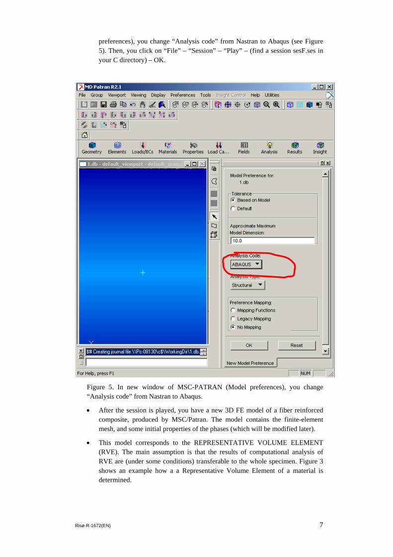
preferences), you change “Analysis code” from Nastran to Abaqus (see Figure 5). Then, you click on “File” – “Session” – “Play” – (find a session sesF.ses in your C directory) – OK.
Figure 5. In new window of MSC-PATRAN (Model preferences), you change “Analysis code” from Nastran to Abaqus.
• After the session is played, you have a new 3D FE model of a fiber reinforced composite, produced by MSC/Patran. The model contains the finite-element mesh, and some initial properties of the phases (which will be modified later).
• This model corresponds to the REPRESENTATIVE VOLUME ELEMENT (RVE). The main assumption is that the results of computational analysis of RVE are (under some conditions) transferable to the whole specimen. Figure 3 shows an example how a a Representative Volume Element of a material is determined.
8 Risø-R-1672(EN)
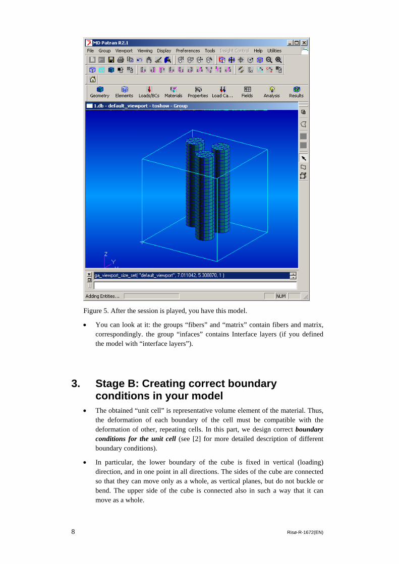
Figure 5. After the session is played, you have this model.
• You can look at it: the groups “fibers” and “matrix” contain fibers and matrix, correspondingly. the group “infaces” contains Interface layers (if you defined the model with “interface layers”).
3. Stage B: Creating correct boundary conditions in your model
• The obtained “unit cell” is representative volume element of the material. Thus, the deformation of each boundary of the cell must be compatible with the deformation of other, repeating cells. In this part, we design correct boundary conditions for the unit cell (see [2] for more detailed description of different boundary conditions).
• In particular, the lower boundary of the cube is fixed in vertical (loading) direction, and in one point in all directions. The sides of the cube are connected so that they can move only as a whole, as vertical planes, but do not buckle or bend. The upper side of the cube is connected also in such a way that it can move as a whole.

Risø-R-1672(EN) 9
• In order to do it, we create 6 group of nodes (or Node Sets) in PATRAN. The group of the nodes on the upper side should be called UPPER, on the lower side – LOWER, on other sides – NORTH, SOUTH, EAST and WEST (correspondingly to four world directions, if one looks from above the cub). Only NODES must be taken into this GROUP. The node groups are created as follows:
o First, we move all the elements on the screen (the command file places only FIBERs on the screen, so it should be changed): “Group” (in upper Toolbar) – “Post” (in Menu of “Group”) – chose “default_group”-Apply-Cancel
o Creating the node set “UPPER”: Place the cube so that Z-axis is directed vertically (Figure 7, red line shows the point). You go to “Group” (upper Toolbar) – “Group create” – “New group name” (write “UPPER”, see white Callout on figure 8) – “Group content” – “Entity Selection” - click “FEM entity only” (blue callout on Figure 8)- click “Node” (the same place which is marked by blue callout in figure 8)- choose (with mouse) the Nodes in the Upper Side (green square on Figure 7).
Figure 7. Place the cube so that Z-axis is directed vertically.

10 Risø-R-1672(EN)
Figure 8. Creating Group Node
o The node sets LOWER, NORTH, SOUTH, EAST and WEST are created in a similar way.
• NOTE: if you have INTERFACE layers in the model, do not include the NODES from the interface layers into the group UPPER.
• Further, you should fix the CUBE, by creating the Node Sets (NSET) fix000 (the node with coordinates 0,0,0) and fixXZ (with coordinates Y=0)
4. Stage C: Creating and editing the ABAQUS input file
• Next, we produce Input file for ABAQUS: click “Analysis” – Analyze- Entire Model – Full Run- Write Jobname “anyname.inp”. The, the file anyname.inp is produced.
• The file must be edited in a text editor (like Notepad or Wordpad). The Editing should go as follows:
UPPER
”FEM entity only”

Risø-R-1672(EN) 11
o Search for the work STEP line in the file. Instead of the old command line with STEP command and below to the end, you write there the text given on Figure 9.
Figure 9. These command lines defines the availability of one point (TIP) which is connected to all the nodes in the UPPER node set. Further, it defines the amount of steps, viscoelasticity of the problem and output parameters
o Remove the 1st Node from node set NSET UPPER, and write it NSET TIP: for instance, if NSET UPPER is written in the INP File as
one has to rewrite it as follows (also, modifying the line *NSET,NSET=TIP 100, given in Figure 9, first two lines)
:
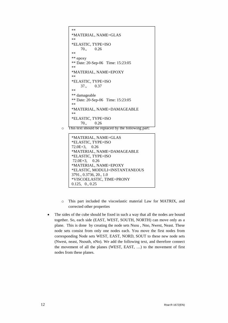
• Determining the material properrties of the phases: now, the “Material Part” of the INP File looks as follows:
*NSET, NSET=UPPER, GENERATE 201, 224,
*NSET, NSET=UPPER, GENERATE 202, 224, 1 *NSET,NSET=TIP 201,
*NSET,NSET=TIP 100, *EQUATION 2 UPPER,3,1.,TIP,3,-1. *STEP,NLGEOM,INC=100 *VISCO 1.0, 100.0 *FILE FORMAT, ASCII ** load *BOUNDARY, OP=MOD TIP, 3,3, 0.3 *NODE FILE, FREQ=1 U *NODE FILE,NSET=TIP, FREQUENCY=1 U,RF *NODE PRINT,NSET=TIP, FREQUENCY=1 U3,RF3 *EL FILE, FREQ=1 S, E *END STEP
12 Risø-R-1672(EN)
o This text should be replaced by the following part:
o This part included the viscoelastic material Law for MATRIX, and corrected other properties
• The sides of the cube should be fixed in such a way that all the nodes are bound together. So, each side (EAST, WEST, SOUTH, NORTH) can move only as a plane. This is done by creating the node sets Nsou , Nno, Nwest, Neast. These node sets consist from only one nodes each. You move the first nodes from corresponding Node sets WEST, EAST, NORD, SOUT to these new node sets (Nwest, neast, Nsouth, nNo). We add the following text, and therefore connect the movement of all the planes (WEST, EAST, …) to the movement of first nodes from these planes.
*MATERIAL, NAME=GLAS *ELASTIC, TYPE=ISO 72.0E+3, 0.26 *MATERIAL, NAME=DAMAGEABLE *ELASTIC, TYPE=ISO 72.0E+3, 0.26 *MATERIAL, NAME=EPOXY *ELASTIC, MODULI=INSTANTANEOUS 3791., 0.3736, 20., 1.0 *VISCOELASTIC, TIME=PRONY 0.125, 0., 0.25
** *MATERIAL, NAME=GLAS ** *ELASTIC, TYPE=ISO 70., 0.26 ** ** epoxy ** Date: 20-Sep-06 Time: 15:23:05 ** *MATERIAL, NAME=EPOXY ** *ELASTIC, TYPE=ISO 37., 0.37 ** ** damageable ** Date: 20-Sep-06 Time: 15:23:05 ** *MATERIAL, NAME=DAMAGEABLE ** *ELASTIC, TYPE=ISO 70., 0.26

Risø-R-1672(EN) 13
• Then, we fix the points FIX000 and FIXXZ. To do this, we add the following text:
5. Stage D: Running the model with ABAQUS. • Now, you can run the model with ABAQUS, and look at the results (for
comparison, see Attachment 1).
6. Stage E: Modelling damage evolution • In the previous steps, we generated 3D finite element model of a fiber reinforced
polymer composite subject to vertical tensile loading along the fibers. As a result, we could obtain the stress and strain distributions in the material. Below, we consider shortly how we can expand this model to include damage and fracture in fibers.
• For an overview of different methods of damage modelling, you are welcome to read the sources [1, 3, 4, 6]. Here we use the Element Weakening Techniques: a finite element, in which stress or other parameter exceeds some critical level, loses most of its stiffness [1, 4]. This method is realised in the ABAQUS
*BOUNDARY FIX000, 1,3 *BOUNDARY FIXXZ, 1 FIXXZ, 2 *BOUNDARY LOWER, 3
*NSET,NSET=Nwest 15000, *EQUATION 2 WEST,1,1.,Nwest,1,-1. *NSET,NSET=Neast 15001, *EQUATION 2 EAST,1,1.,Neast,1,-1. *NSET,NSET=Nno 15013, *EQUATION 2 NORTH,2,1.,Nno,2,-1. *NSET,NSET=Nsou 16077, *EQUATION 2 SOUTH,2,1.,Nsou,2,-1.

14 Risø-R-1672(EN)
subroutine User Defined Field. The subroutine (file “damage.f) is available from the authors.
• If we simulate damage in some phase (for instance, we introduce damageable elements in fibers or in matrix or in interface, or take all the phase as damageable), we should carry out the following modifications of the INP File:
o In the line, just above the *END STEP, one should write:
o
o The MATERIAL PART should be replaced by the following text:
o
• When we run the ABAQUS job, we include the user subroutine in the command.
*MATERIAL, NAME=GLAS *ELASTIC, TYPE=ISO 72.0E+3, 0.26 *** *MATERIAL, NAME=DAMAGEABLE *ELASTIC, TYPE=ISO, DEPENDENCIES=1 72.0E+3, 0.26, 20., 1.0 7., 0.26, 20., 2.0 *DEPVAR 1, *USER DEFINED FIELD ** *MATERIAL, NAME=EPOXY *ELASTIC, MODULI=INSTANTANEOUS 3791., 0.3736, 20., 1.0 *VISCOELASTIC, TIME=PRONY 0.125, 0., 0.25
*EL FILE, FREQ=1 S, E, PE, SINV, SP, SDV, FV, EP

Risø-R-1672(EN) 15
References: 1. L. Mishnaevsky Jr. Computational Mesomechanics of Composites, John Wiley and
Sons, London, 2007 2. S. Schmauder and L. Mishnaevsky Jr., Micromechanics and Nanosimulation of Metals
and Composites ", 2008, Springer, 430 pp. 3. D. Raabe, Computational Materials Science: The Simulation of Materials
Microstructures and Properties, Wiley, 1998 4. Böhm, H.J. (1998) A short introduction to basic aspects of continuum micromechanics,
TU Wien, Vienna, 102 pp. (http://www.ilsb.tuwien.ac.at/links/downloads/cdlfmdrep03.pdf)
5. L. Mishnaevsky Jr and S. Schmauder, Continuum Mesomechanical Finite Element Modeling in Materials Development: a State-of-the-Art Review, Applied Mechanics Reviews, Vol. 54, 1, 2001, pp. 49-69
6. L. Mishnaevsky Jr and P. Brøndsted, 3D numerical modelling of damage initiation in unidirectional fiber reinforced composites with ductile matrix, Materials Science and Engineering: A, Vol. 498, Issues 1-2, 2008, pp. 81-86
7. L. Mishnaevsky Jr et al., Computational Modeling of Crack Propagation in Real Microstructures of Steels and Virtual Testing of Artificially Designed Materials, Int. J. Fracture, 120, 4, 2003, pp. 581-600 (http://www.risoe.dk/About_risoe/research_departments/AFM/CV/lemi/~/media/risoe_dk/about_risoe/afm/cv/documents/lemi_prior/pap_lippmann.ashx)

www.risoe.dtu.dk