MicroMax Interrupters User Guide - American …€¦ · MicroMax Interrupters User Guide Getting...
56
MicroMax GPS300 & GPS350 User Guide MicroMax GPS300 & GPS350 User Guide Proven compliance solutions. Proven compliance solutions. Relentless service.
Transcript of MicroMax Interrupters User Guide - American …€¦ · MicroMax Interrupters User Guide Getting...

MicroMax GPS300 & GPS350 User Guide
MicroMax GPS300 & GPS350
User GuideProven compliance solutions.
Proven compliance solutions. Relentless service.

Information in this document is subject to change without notice.
©2016-2017 American Innovations, Ltd. All rights reserved.
American Innovations | www.aiworldwide.com | 12211 Technology Blvd | Austin, TX 78727
Reproduction in any manner whatsoever without the written permission of American Innovations is strictly forbidden.
The American Innovations logo and icon, including MicroMax and Bullhorn, are marks of American Innovations, Ltd. Other trademarks and trade names may be used in this document to refer to either the entities claiming the marks and names or their products. American Innovations, Ltd. disclaims any proprietary interest in trademarks and trade names other than its own.
March 2017 122204-000, Rev. 5
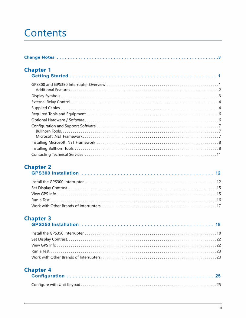
Contents
Change Notes . . . . . . . . . . . . . . . . . . . . . . . . . . . . . . . . . . . . . . . . . . . . . . . . . . . . . . . . . . . .v
Chapter 1Getting Started . . . . . . . . . . . . . . . . . . . . . . . . . . . . . . . . . . . . . . . . . . . . . . . . . 1
GPS300 and GPS350 Interrupter Overview . . . . . . . . . . . . . . . . . . . . . . . . . . . . . . . . . . . . . . . . . . . . . . . . . . . . . . . . . 1Additional Features . . . . . . . . . . . . . . . . . . . . . . . . . . . . . . . . . . . . . . . . . . . . . . . . . . . . . . . . . . . . . . . . . . . . . . . . . . . 2
Display Symbols . . . . . . . . . . . . . . . . . . . . . . . . . . . . . . . . . . . . . . . . . . . . . . . . . . . . . . . . . . . . . . . . . . . . . . . . . . . . . . . . 3External Relay Control . . . . . . . . . . . . . . . . . . . . . . . . . . . . . . . . . . . . . . . . . . . . . . . . . . . . . . . . . . . . . . . . . . . . . . . . . . . 4Supplied Cables . . . . . . . . . . . . . . . . . . . . . . . . . . . . . . . . . . . . . . . . . . . . . . . . . . . . . . . . . . . . . . . . . . . . . . . . . . . . . . . . 4Required Tools and Equipment . . . . . . . . . . . . . . . . . . . . . . . . . . . . . . . . . . . . . . . . . . . . . . . . . . . . . . . . . . . . . . . . . . . 6Optional Hardware / Software . . . . . . . . . . . . . . . . . . . . . . . . . . . . . . . . . . . . . . . . . . . . . . . . . . . . . . . . . . . . . . . . . . . . 6Configuration and Support Software . . . . . . . . . . . . . . . . . . . . . . . . . . . . . . . . . . . . . . . . . . . . . . . . . . . . . . . . . . . . . . 7
Bullhorn Tools . . . . . . . . . . . . . . . . . . . . . . . . . . . . . . . . . . . . . . . . . . . . . . . . . . . . . . . . . . . . . . . . . . . . . . . . . . . . . . . . 7Microsoft .NET Framework. . . . . . . . . . . . . . . . . . . . . . . . . . . . . . . . . . . . . . . . . . . . . . . . . . . . . . . . . . . . . . . . . . . . . 7
Installing Microsoft .NET Framework . . . . . . . . . . . . . . . . . . . . . . . . . . . . . . . . . . . . . . . . . . . . . . . . . . . . . . . . . . . . . . 8Installing Bullhorn Tools . . . . . . . . . . . . . . . . . . . . . . . . . . . . . . . . . . . . . . . . . . . . . . . . . . . . . . . . . . . . . . . . . . . . . . . . . 8Contacting Technical Services . . . . . . . . . . . . . . . . . . . . . . . . . . . . . . . . . . . . . . . . . . . . . . . . . . . . . . . . . . . . . . . . . . . 11
Chapter 2GPS300 Installation . . . . . . . . . . . . . . . . . . . . . . . . . . . . . . . . . . . . . . . . . . . . 12
Install the GPS300 Interrupter . . . . . . . . . . . . . . . . . . . . . . . . . . . . . . . . . . . . . . . . . . . . . . . . . . . . . . . . . . . . . . . . . . . 12Set Display Contrast. . . . . . . . . . . . . . . . . . . . . . . . . . . . . . . . . . . . . . . . . . . . . . . . . . . . . . . . . . . . . . . . . . . . . . . . . . . . 15View GPS Info . . . . . . . . . . . . . . . . . . . . . . . . . . . . . . . . . . . . . . . . . . . . . . . . . . . . . . . . . . . . . . . . . . . . . . . . . . . . . . . . . 15Run a Test . . . . . . . . . . . . . . . . . . . . . . . . . . . . . . . . . . . . . . . . . . . . . . . . . . . . . . . . . . . . . . . . . . . . . . . . . . . . . . . . . . . . 16Work with Other Brands of Interrupters. . . . . . . . . . . . . . . . . . . . . . . . . . . . . . . . . . . . . . . . . . . . . . . . . . . . . . . . . . . 17
Chapter 3GPS350 Installation . . . . . . . . . . . . . . . . . . . . . . . . . . . . . . . . . . . . . . . . . . . . 18
Install the GPS350 Interrupter . . . . . . . . . . . . . . . . . . . . . . . . . . . . . . . . . . . . . . . . . . . . . . . . . . . . . . . . . . . . . . . . . . . 18Set Display Contrast. . . . . . . . . . . . . . . . . . . . . . . . . . . . . . . . . . . . . . . . . . . . . . . . . . . . . . . . . . . . . . . . . . . . . . . . . . . . 22View GPS Info . . . . . . . . . . . . . . . . . . . . . . . . . . . . . . . . . . . . . . . . . . . . . . . . . . . . . . . . . . . . . . . . . . . . . . . . . . . . . . . . . 22Run a Test . . . . . . . . . . . . . . . . . . . . . . . . . . . . . . . . . . . . . . . . . . . . . . . . . . . . . . . . . . . . . . . . . . . . . . . . . . . . . . . . . . . . 23Work with Other Brands of Interrupters. . . . . . . . . . . . . . . . . . . . . . . . . . . . . . . . . . . . . . . . . . . . . . . . . . . . . . . . . . . 23
Chapter 4Configuration . . . . . . . . . . . . . . . . . . . . . . . . . . . . . . . . . . . . . . . . . . . . . . . . . 25
Configure with Unit Keypad . . . . . . . . . . . . . . . . . . . . . . . . . . . . . . . . . . . . . . . . . . . . . . . . . . . . . . . . . . . . . . . . . . . . . 25
iii
MicroMax Interrupters User Guide
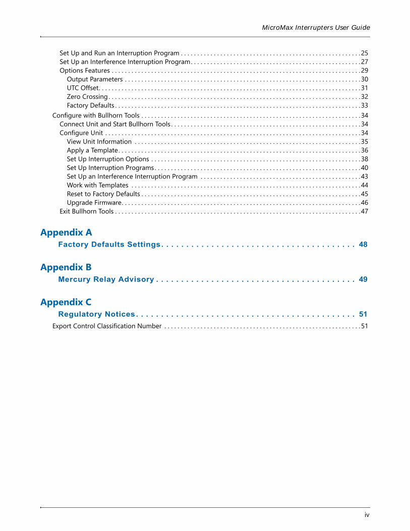
Set Up and Run an Interruption Program . . . . . . . . . . . . . . . . . . . . . . . . . . . . . . . . . . . . . . . . . . . . . . . . . . . . . . . 25Set Up an Interference Interruption Program. . . . . . . . . . . . . . . . . . . . . . . . . . . . . . . . . . . . . . . . . . . . . . . . . . . . 27Options Features . . . . . . . . . . . . . . . . . . . . . . . . . . . . . . . . . . . . . . . . . . . . . . . . . . . . . . . . . . . . . . . . . . . . . . . . . . . . 29
Output Parameters . . . . . . . . . . . . . . . . . . . . . . . . . . . . . . . . . . . . . . . . . . . . . . . . . . . . . . . . . . . . . . . . . . . . . . . . 30UTC Offset. . . . . . . . . . . . . . . . . . . . . . . . . . . . . . . . . . . . . . . . . . . . . . . . . . . . . . . . . . . . . . . . . . . . . . . . . . . . . . . . 31Zero Crossing . . . . . . . . . . . . . . . . . . . . . . . . . . . . . . . . . . . . . . . . . . . . . . . . . . . . . . . . . . . . . . . . . . . . . . . . . . . . . 32Factory Defaults . . . . . . . . . . . . . . . . . . . . . . . . . . . . . . . . . . . . . . . . . . . . . . . . . . . . . . . . . . . . . . . . . . . . . . . . . . .33
Configure with Bullhorn Tools . . . . . . . . . . . . . . . . . . . . . . . . . . . . . . . . . . . . . . . . . . . . . . . . . . . . . . . . . . . . . . . . . . . 34Connect Unit and Start Bullhorn Tools . . . . . . . . . . . . . . . . . . . . . . . . . . . . . . . . . . . . . . . . . . . . . . . . . . . . . . . . . . 34Configure Unit . . . . . . . . . . . . . . . . . . . . . . . . . . . . . . . . . . . . . . . . . . . . . . . . . . . . . . . . . . . . . . . . . . . . . . . . . . . . . . 34
View Unit Information . . . . . . . . . . . . . . . . . . . . . . . . . . . . . . . . . . . . . . . . . . . . . . . . . . . . . . . . . . . . . . . . . . . . . 35Apply a Template. . . . . . . . . . . . . . . . . . . . . . . . . . . . . . . . . . . . . . . . . . . . . . . . . . . . . . . . . . . . . . . . . . . . . . . . . . 36Set Up Interruption Options . . . . . . . . . . . . . . . . . . . . . . . . . . . . . . . . . . . . . . . . . . . . . . . . . . . . . . . . . . . . . . . . 38Set Up Interruption Programs. . . . . . . . . . . . . . . . . . . . . . . . . . . . . . . . . . . . . . . . . . . . . . . . . . . . . . . . . . . . . . . 40Set Up an Interference Interruption Program . . . . . . . . . . . . . . . . . . . . . . . . . . . . . . . . . . . . . . . . . . . . . . . . . 43Work with Templates . . . . . . . . . . . . . . . . . . . . . . . . . . . . . . . . . . . . . . . . . . . . . . . . . . . . . . . . . . . . . . . . . . . . . . 44Reset to Factory Defaults . . . . . . . . . . . . . . . . . . . . . . . . . . . . . . . . . . . . . . . . . . . . . . . . . . . . . . . . . . . . . . . . . . . 45Upgrade Firmware. . . . . . . . . . . . . . . . . . . . . . . . . . . . . . . . . . . . . . . . . . . . . . . . . . . . . . . . . . . . . . . . . . . . . . . . . 46
Exit Bullhorn Tools . . . . . . . . . . . . . . . . . . . . . . . . . . . . . . . . . . . . . . . . . . . . . . . . . . . . . . . . . . . . . . . . . . . . . . . . . . .47
Appendix AFactory Defaults Settings. . . . . . . . . . . . . . . . . . . . . . . . . . . . . . . . . . . . . . . 48
Appendix BMercury Relay Advisory . . . . . . . . . . . . . . . . . . . . . . . . . . . . . . . . . . . . . . . . 49
Appendix CRegulatory Notices . . . . . . . . . . . . . . . . . . . . . . . . . . . . . . . . . . . . . . . . . . . . 51
Export Control Classification Number . . . . . . . . . . . . . . . . . . . . . . . . . . . . . . . . . . . . . . . . . . . . . . . . . . . . . . . . . . . . 51
iv
v
Change NotesThe following list identifies new or updated information included in the current release of this manual:
• Chapter 4, Configuration on page 25: updated configuration software to Bullhorn Tools.
Getting Started 1
The MicroMax® GPS300 and GPS350 interrupters are programmable, GPS-synchronized, current interrupters. The information in this guide is intended for authorized service personnel who plan to install and program an interrupter for service.
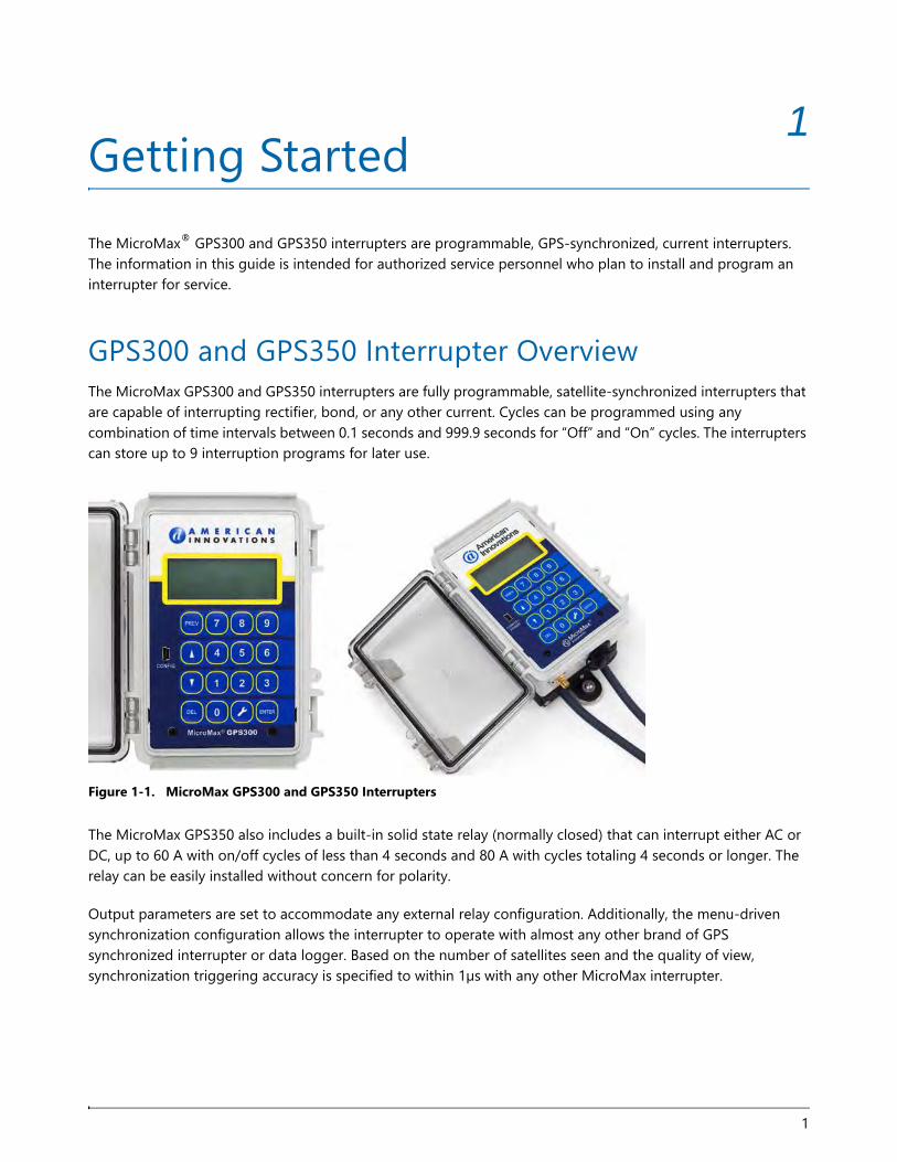
GPS300 and GPS350 Interrupter OverviewThe MicroMax GPS300 and GPS350 interrupters are fully programmable, satellite-synchronized interrupters that are capable of interrupting rectifier, bond, or any other current. Cycles can be programmed using any combination of time intervals between 0.1 seconds and 999.9 seconds for “Off” and “On” cycles. The interrupters can store up to 9 interruption programs for later use.
Figure 1-1. MicroMax GPS300 and GPS350 Interrupters
The MicroMax GPS350 also includes a built-in solid state relay (normally closed) that can interrupt either AC or DC, up to 60 A with on/off cycles of less than 4 seconds and 80 A with cycles totaling 4 seconds or longer. The relay can be easily installed without concern for polarity.
Output parameters are set to accommodate any external relay configuration. Additionally, the menu-driven synchronization configuration allows the interrupter to operate with almost any other brand of GPS synchronized interrupter or data logger. Based on the number of satellites seen and the quality of view, synchronization triggering accuracy is specified to within 1µs with any other MicroMax interrupter.
1
MicroMax Interrupters User Guide
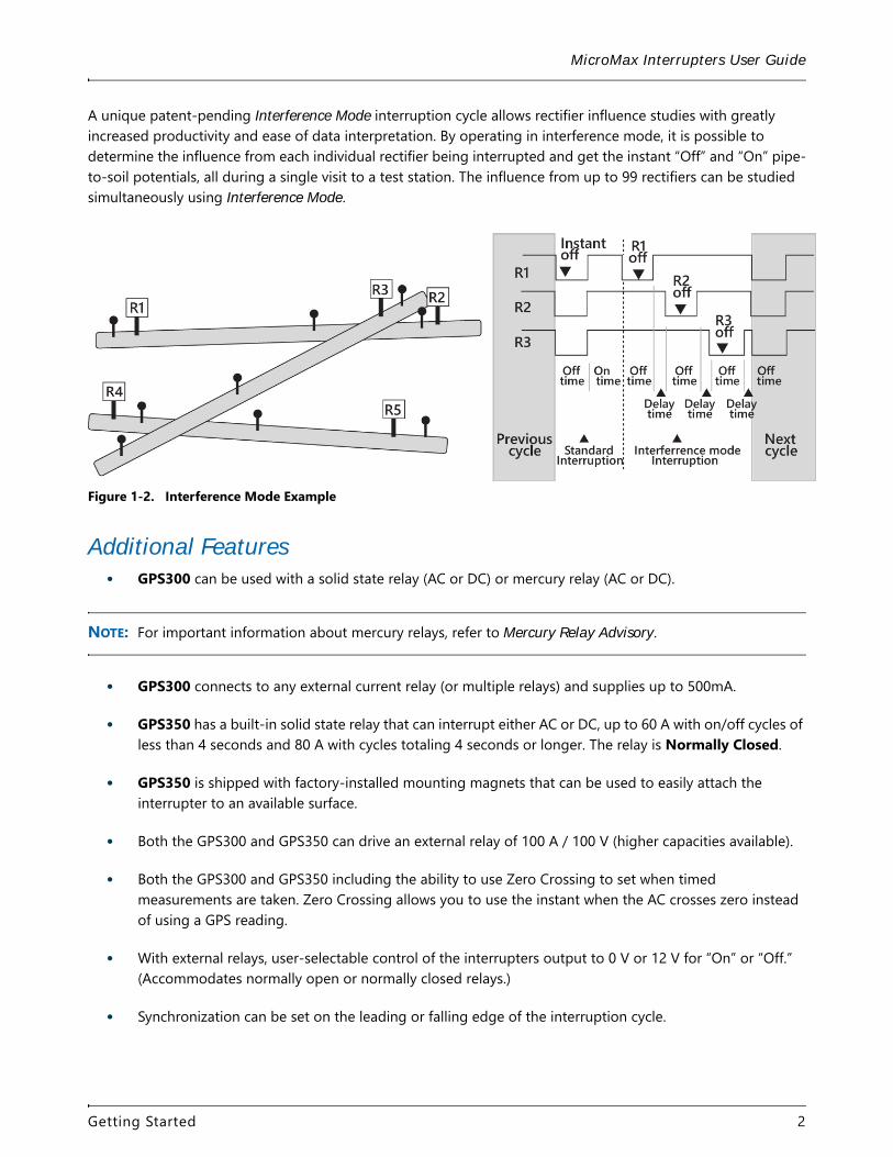
A unique patent-pending Interference Mode interruption cycle allows rectifier influence studies with greatly increased productivity and ease of data interpretation. By operating in interference mode, it is possible to determine the influence from each individual rectifier being interrupted and get the instant “Off” and “On” pipe-to-soil potentials, all during a single visit to a test station. The influence from up to 99 rectifiers can be studied simultaneously using Interference Mode.
Figure 1-2. Interference Mode Example
Additional Features• GPS300 can be used with a solid state relay (AC or DC) or mercury relay (AC or DC).
NOTE: For important information about mercury relays, refer to Mercury Relay Advisory.
• GPS300 connects to any external current relay (or multiple relays) and supplies up to 500mA.
• GPS350 has a built-in solid state relay that can interrupt either AC or DC, up to 60 A with on/off cycles of less than 4 seconds and 80 A with cycles totaling 4 seconds or longer. The relay is Normally Closed.
• GPS350 is shipped with factory-installed mounting magnets that can be used to easily attach the interrupter to an available surface.
• Both the GPS300 and GPS350 can drive an external relay of 100 A / 100 V (higher capacities available).
• Both the GPS300 and GPS350 including the ability to use Zero Crossing to set when timed measurements are taken. Zero Crossing allows you to use the instant when the AC crosses zero instead of using a GPS reading.
• With external relays, user-selectable control of the interrupters output to 0 V or 12 V for “On” or “Off.” (Accommodates normally open or normally closed relays.)
• Synchronization can be set on the leading or falling edge of the interruption cycle.
Getting Started 2
MicroMax Interrupters User Guide
• Interruption continues automatically after power is disrupted.
• Cycle range up to 999.9 seconds in 0.1 second increments.
• Synchronization triggering accuracy is within 1µs with any other GPS300 or GPS350 interrupter and collectively is less than 5µs after the PPS signal (precise positioning service signal) as provided by the GPS satellite constellation, even when only one satellite is visible.
• Fully programmable between the following schedules: continuous, daily, start/stop, and interference. Nine different interruption programs can be stored for later use.
• Power from AC or DC with a wide range of input voltages.
• Allows for full cathodic protection (CP) polarization when the interrupter is not in use (rectifier “on” and no interruption).
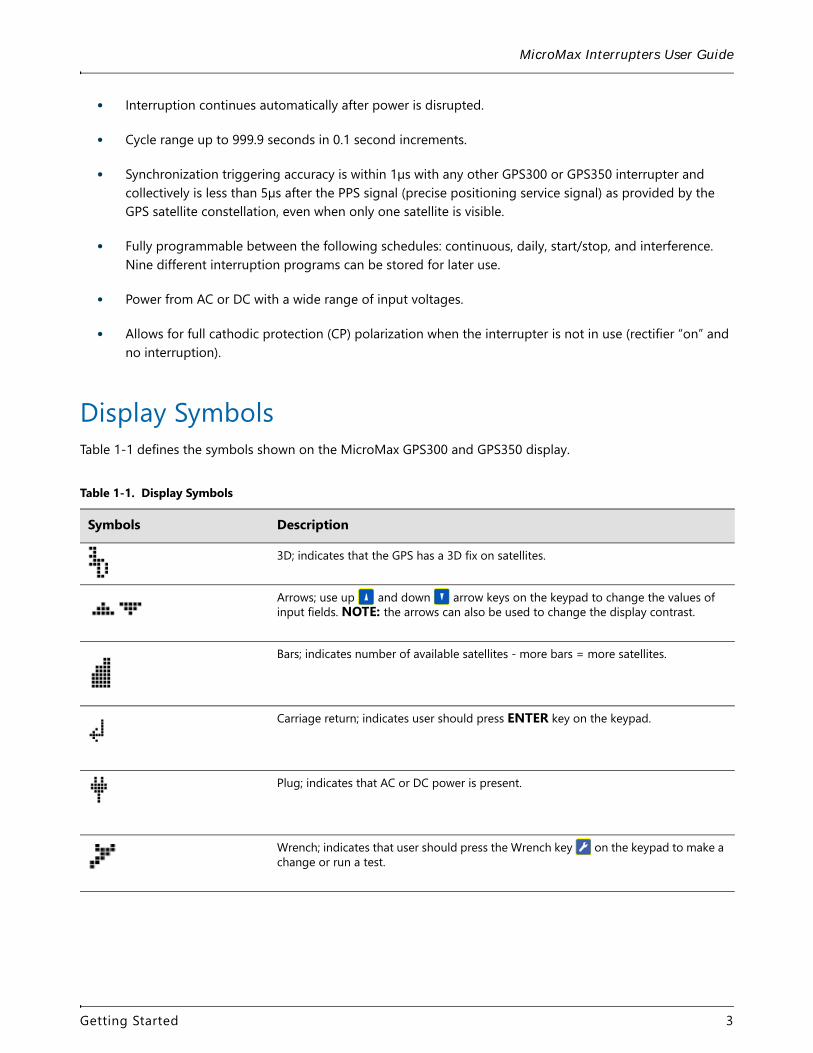
Display SymbolsTable 1-1 defines the symbols shown on the MicroMax GPS300 and GPS350 display.
Table 1-1. Display Symbols
Symbols Description
3D; indicates that the GPS has a 3D fix on satellites.
Arrows; use up and down arrow keys on the keypad to change the values of input fields. NOTE: the arrows can also be used to change the display contrast.
Bars; indicates number of available satellites - more bars = more satellites.
Carriage return; indicates user should press ENTER key on the keypad.
Plug; indicates that AC or DC power is present.
Wrench; indicates that user should press the Wrench key on the keypad to make a change or run a test.
Getting Started 3
MicroMax Interrupters User Guide
External Relay ControlYou can connect the GPS300 or GPS350 interrupter to almost any external current relay (or multiple relays) using a 12V control. Depending on the configuration, the interrupter supplies up to 500mA (12V) relay control current. As a result, numerous relays can be controlled with one interrupter. This leads to significant cost savings in areas where multiple current sources in a confined area need to be switched. The GPS300 and GPS350 can be set to accommodate normally open and normally closed relays. There are several relay options for switching either AC or DC at various loads.
Additionally, the GPS350 includes a built-in solid state relay that can interrupt either AC or DC, up to 60 A with on/off cycles of less than 4 seconds and 80 A with cycles totaling 4 seconds or longer. The GPS350 internal relay can be easily installed without concern for polarity.
Supplied CablesThe following cables are provided in the installation kit with the GPS300 and GPS350 interrupters. Refer to Figure 1-5 and Figure 1-6 for the location of input connections. Both of these interrupters consume approximately 120 mA. External relay current consumption is additional, which is typically less than 10 mA for a solid state relay and as high as 400mA for a mechanical mercury relay.
NOTE: Refer to Chapter 2, GPS300 Installation on page 12 or Chapter 3, GPS350 Installation on page 18 for instructions on how to connect the cables.
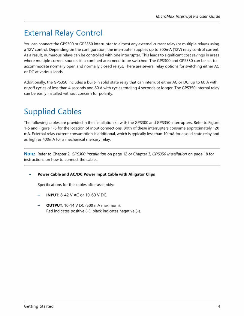
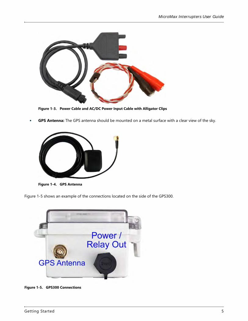
• Power Cable and AC/DC Power Input Cable with Alligator Clips
Specifications for the cables after assembly:
– INPUT: 8-42 V AC or 10-60 V DC.
– OUTPUT: 10-14 V DC (500 mA maximum). Red indicates positive (+); black indicates negative (–).
Getting Started 4
MicroMax Interrupters User Guide
Figure 1-3. Power Cable and AC/DC Power Input Cable with Alligator Clips
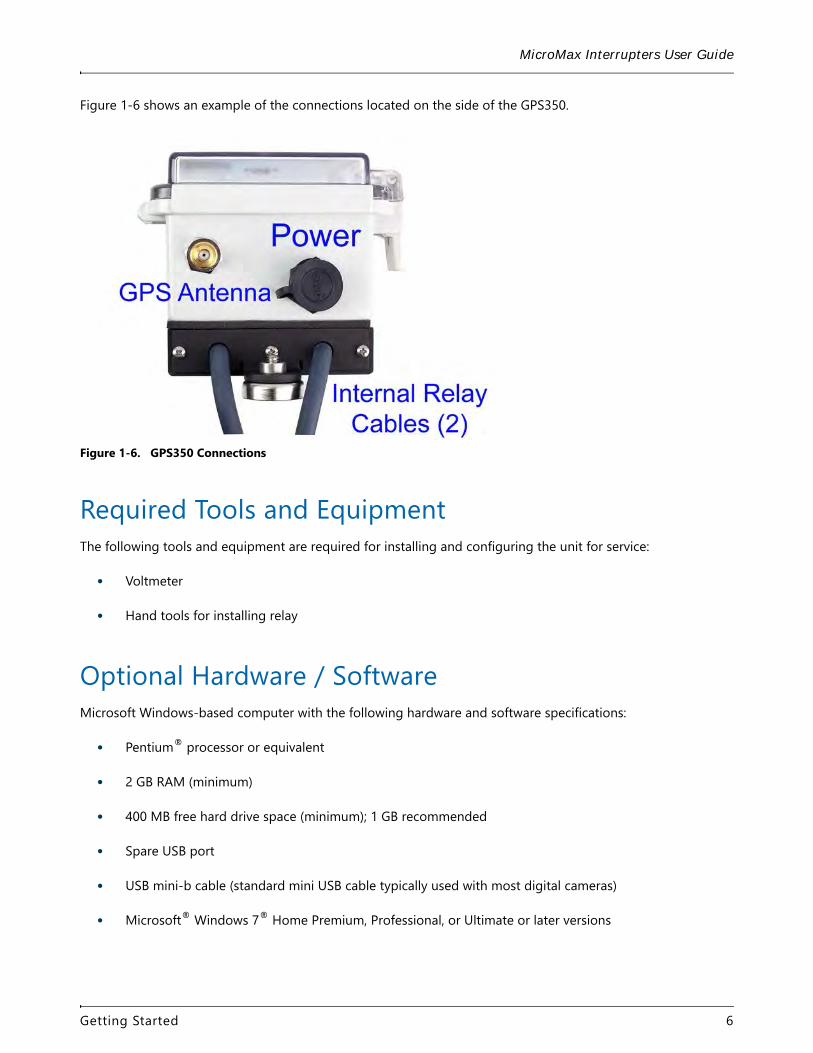
• GPS Antenna: The GPS antenna should be mounted on a metal surface with a clear view of the sky.
Figure 1-4. GPS Antenna
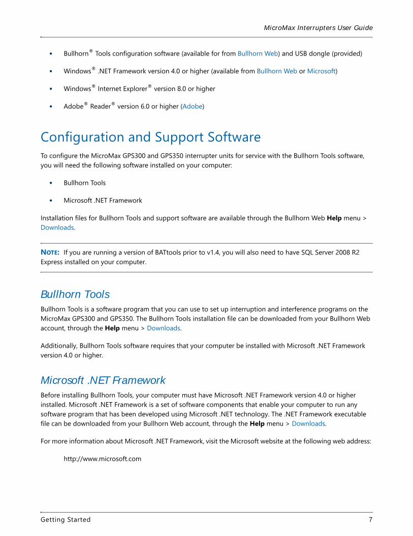
Figure 1-5 shows an example of the connections located on the side of the GPS300.
Figure 1-5. GPS300 Connections
Getting Started 5
MicroMax Interrupters User Guide
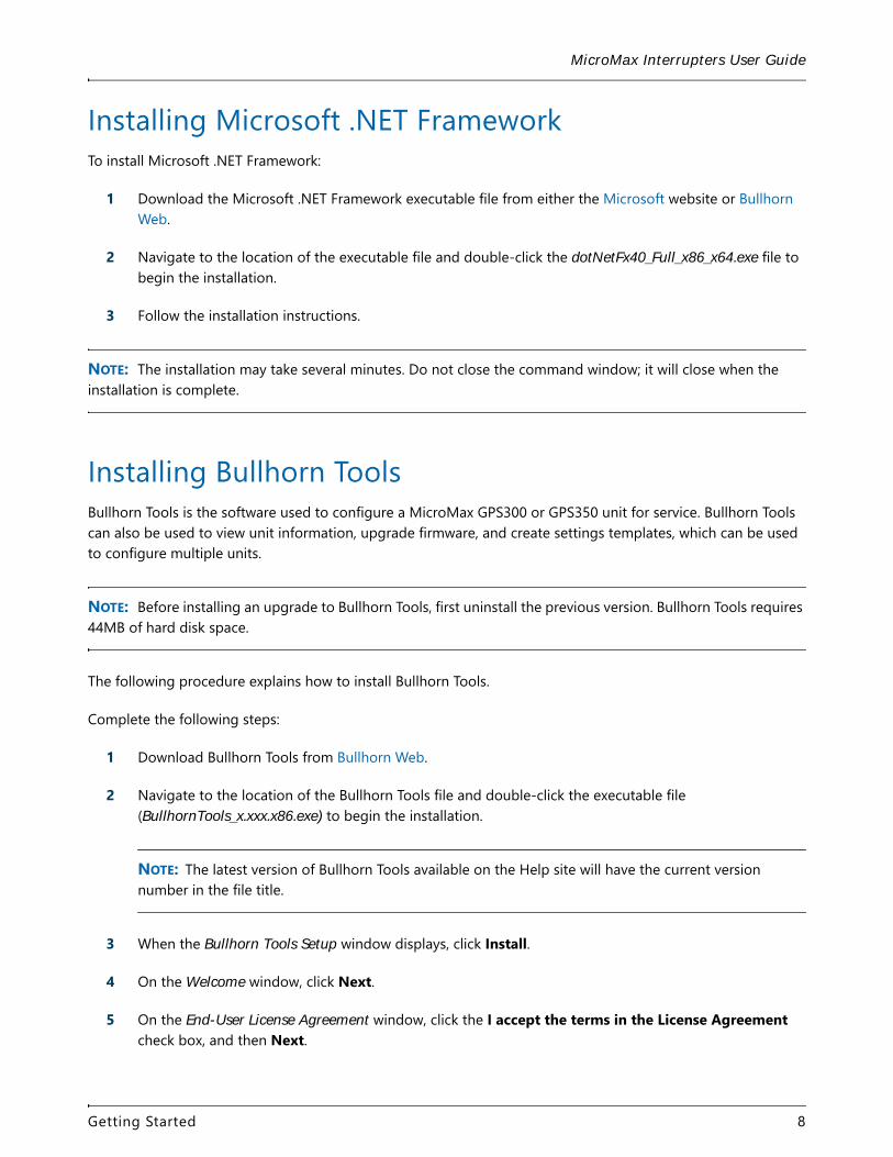
Figure 1-6 shows an example of the connections located on the side of the GPS350.
Figure 1-6. GPS350 Connections
Required Tools and EquipmentThe following tools and equipment are required for installing and configuring the unit for service:
• Voltmeter
• Hand tools for installing relay
Optional Hardware / SoftwareMicrosoft Windows-based computer with the following hardware and software specifications:
• Pentium® processor or equivalent
• 2 GB RAM (minimum)
• 400 MB free hard drive space (minimum); 1 GB recommended
• Spare USB port
• USB mini-b cable (standard mini USB cable typically used with most digital cameras)
• Microsoft® Windows 7® Home Premium, Professional, or Ultimate or later versions
Getting Started 6
MicroMax Interrupters User Guide
• Bullhorn® Tools configuration software (available for from Bullhorn Web) and USB dongle (provided)
• Windows® .NET Framework version 4.0 or higher (available from Bullhorn Web or Microsoft)
• Windows® Internet Explorer® version 8.0 or higher
• Adobe® Reader® version 6.0 or higher (Adobe)
Configuration and Support SoftwareTo configure the MicroMax GPS300 and GPS350 interrupter units for service with the Bullhorn Tools software, you will need the following software installed on your computer:
• Bullhorn Tools
• Microsoft .NET Framework
Installation files for Bullhorn Tools and support software are available through the Bullhorn Web Help menu > Downloads.
NOTE: If you are running a version of BATtools prior to v1.4, you will also need to have SQL Server 2008 R2 Express installed on your computer.
Bullhorn ToolsBullhorn Tools is a software program that you can use to set up interruption and interference programs on the MicroMax GPS300 and GPS350. The Bullhorn Tools installation file can be downloaded from your Bullhorn Web account, through the Help menu > Downloads.
Additionally, Bullhorn Tools software requires that your computer be installed with Microsoft .NET Framework version 4.0 or higher.
Microsoft .NET FrameworkBefore installing Bullhorn Tools, your computer must have Microsoft .NET Framework version 4.0 or higher installed. Microsoft .NET Framework is a set of software components that enable your computer to run any software program that has been developed using Microsoft .NET technology. The .NET Framework executable file can be downloaded from your Bullhorn Web account, through the Help menu > Downloads.
For more information about Microsoft .NET Framework, visit the Microsoft website at the following web address:
http://www.microsoft.com
Getting Started 7
MicroMax Interrupters User Guide
Installing Microsoft .NET FrameworkTo install Microsoft .NET Framework:
1 Download the Microsoft .NET Framework executable file from either the Microsoft website or Bullhorn Web.
2 Navigate to the location of the executable file and double-click the dotNetFx40_Full_x86_x64.exe file to begin the installation.
3 Follow the installation instructions.
NOTE: The installation may take several minutes. Do not close the command window; it will close when the installation is complete.
Installing Bullhorn ToolsBullhorn Tools is the software used to configure a MicroMax GPS300 or GPS350 unit for service. Bullhorn Tools can also be used to view unit information, upgrade firmware, and create settings templates, which can be used to configure multiple units.
NOTE: Before installing an upgrade to Bullhorn Tools, first uninstall the previous version. Bullhorn Tools requires 44MB of hard disk space.
The following procedure explains how to install Bullhorn Tools.
Complete the following steps:
1 Download Bullhorn Tools from Bullhorn Web.
2 Navigate to the location of the Bullhorn Tools file and double-click the executable file (BullhornTools_x.xxx.x86.exe) to begin the installation.
NOTE: The latest version of Bullhorn Tools available on the Help site will have the current version number in the file title.
3 When the Bullhorn Tools Setup window displays, click Install.
4 On the Welcome window, click Next.
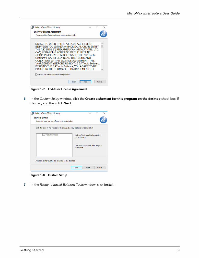
5 On the End-User License Agreement window, click the I accept the terms in the License Agreement check box, and then Next.
Getting Started 8
MicroMax Interrupters User Guide
Figure 1-7. End-User License Agreement
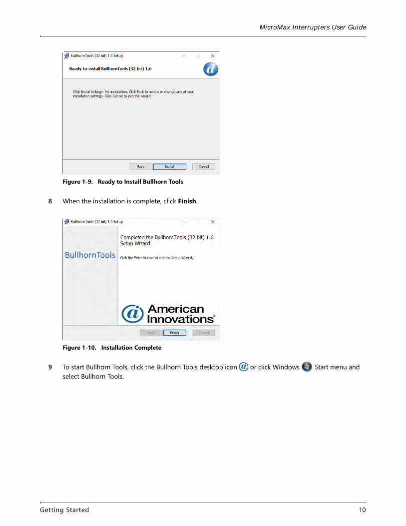
6 In the Custom Setup window, click the Create a shortcut for this program on the desktop check box, if desired, and then click Next.
Figure 1-8. Custom Setup
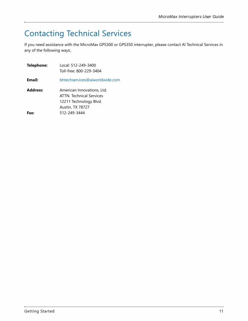
7 In the Ready to install Bullhorn Tools window, click Install.
Getting Started 9
MicroMax Interrupters User Guide
Figure 1-9. Ready to Install Bullhorn Tools
8 When the installation is complete, click Finish.
Figure 1-10. Installation Complete
9 To start Bullhorn Tools, click the Bullhorn Tools desktop icon or click Windows Start menu and select Bullhorn Tools.
Getting Started 10
MicroMax Interrupters User Guide
Contacting Technical ServicesIf you need assistance with the MicroMax GPS300 or GPS350 interrupter, please contact AI Technical Services in any of the following ways:.
Telephone: Local: 512-249-3400Toll-free: 800-229-3404
Email: [email protected]
Address: American Innovations, Ltd.ATTN. Technical Services12211 Technology Blvd.Austin, TX 78727
Fax: 512-249-3444
Getting Started 11
GPS300 Installation 2
The MicroMax GPS300 interrupter consumes approximately 120mA. Relay current consumption is additional, which is typically less than 10mA for a solid state relay and could be as high as 400mA for a mechanical mercury relay.
Install the GPS300 InterrupterWhen completing the following procedure, refer to the section entitled Supplied Cables for input and output voltage specifications.
WARNING: Make sure to follow all precautions when working with the interrupter and high voltage circuits.
WARNING: Do not connect the MicroMax GPS300 to primary power.
Complete the following steps:
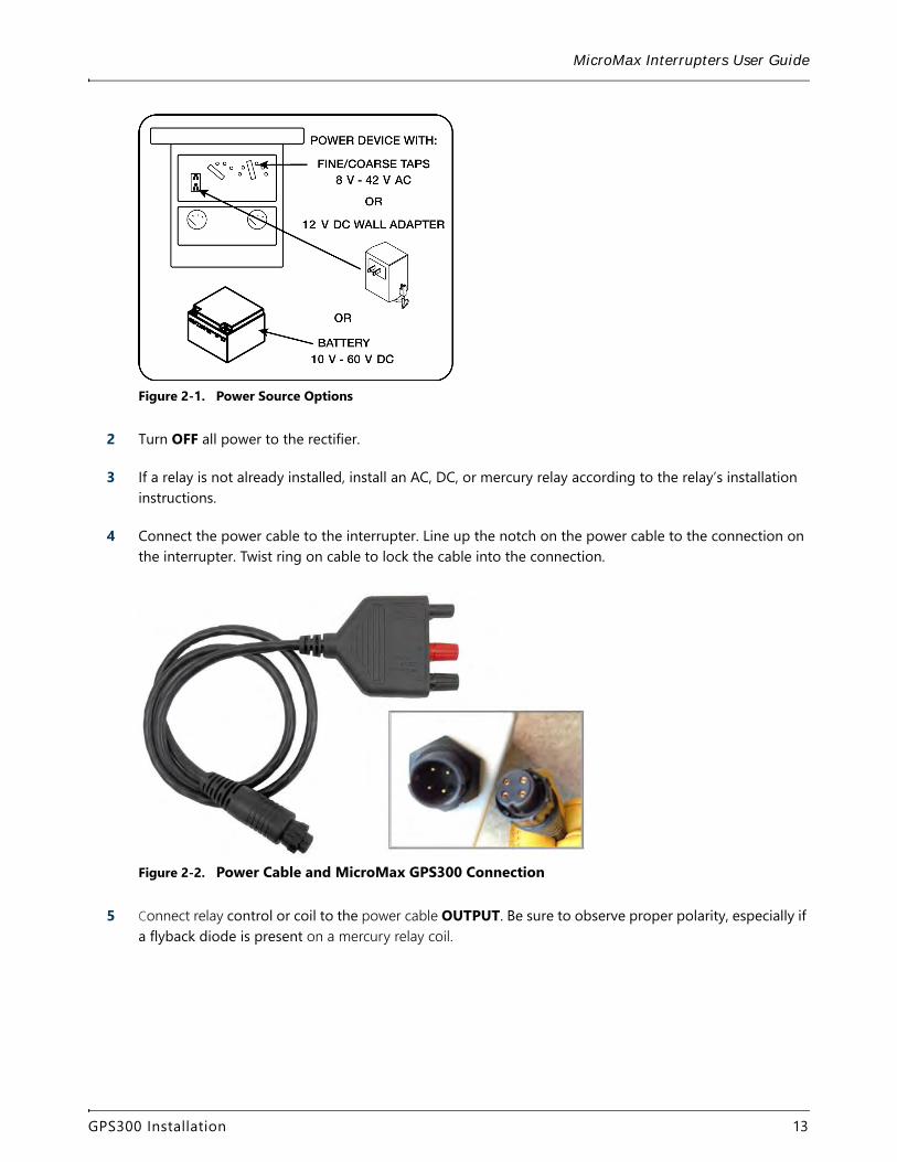
1 Determine how to power the MicroMax GPS300 using one of three possible sources (refer to Figure 2-1):
a Rectifier - with power turned on to the rectifier, use a voltmeter to locate a power source across two available AC taps. The MicroMax GPS300 requires 8-42 V AC or 10-60 V DC.
b A 120 V AC convenience outlet to use with the 12 V DC wall adapter.
c A DC source, such as a 10-60 V DC battery.
12
MicroMax Interrupters User Guide
Figure 2-1. Power Source Options
2 Turn OFF all power to the rectifier.
3 If a relay is not already installed, install an AC, DC, or mercury relay according to the relay’s installation instructions.
4 Connect the power cable to the interrupter. Line up the notch on the power cable to the connection on the interrupter. Twist ring on cable to lock the cable into the connection.
Figure 2-2. Power Cable and MicroMax GPS300 Connection
5 Connect relay control or coil to the power cable OUTPUT. Be sure to observe proper polarity, especially if a flyback diode is present on a mercury relay coil.
GPS300 Installation 13
MicroMax Interrupters User Guide
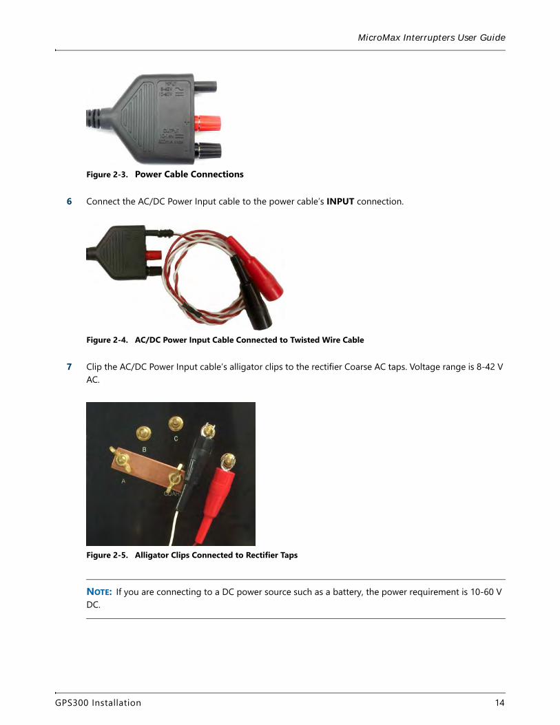
Figure 2-3. Power Cable Connections
6 Connect the AC/DC Power Input cable to the power cable’s INPUT connection.
Figure 2-4. AC/DC Power Input Cable Connected to Twisted Wire Cable
7 Clip the AC/DC Power Input cable’s alligator clips to the rectifier Coarse AC taps. Voltage range is 8-42 V AC.
Figure 2-5. Alligator Clips Connected to Rectifier Taps
NOTE: If you are connecting to a DC power source such as a battery, the power requirement is 10-60 V DC.
GPS300 Installation 14
MicroMax Interrupters User Guide
8 Connect the magnetic-mount, GPS antenna to the GPS connector on the MicroMax GPS300. Mount the GPS antenna on a metal surface making sure the antenna has a clear view of the sky. If a metal surface is unavailable, glue a flat washer on a suitable surface and then place the GPS antenna on the flat washer.
After applying power to the GPS300 interrupter, MicroMax GPS300 information briefly appears in the display.
After the initialization process completes, the interrupter displays the main menu. If the main menu does not display (this may take several minutes), make sure the interrupter is not currently running another program. If another program is running, press PREV and then ENTER.
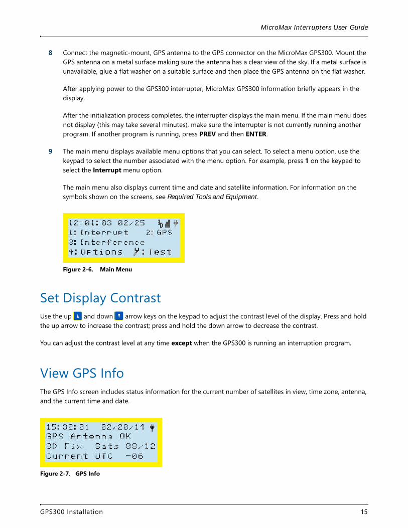
9 The main menu displays available menu options that you can select. To select a menu option, use the keypad to select the number associated with the menu option. For example, press 1 on the keypad to select the Interrupt menu option.
The main menu also displays current time and date and satellite information. For information on the symbols shown on the screens, see Required Tools and Equipment.
Figure 2-6. Main Menu
Set Display ContrastUse the up and down arrow keys on the keypad to adjust the contrast level of the display. Press and hold the up arrow to increase the contrast; press and hold the down arrow to decrease the contrast.
You can adjust the contrast level at any time except when the GPS300 is running an interruption program.
View GPS InfoThe GPS Info screen includes status information for the current number of satellites in view, time zone, antenna, and the current time and date.
Figure 2-7. GPS Info
GPS300 Installation 15
MicroMax Interrupters User Guide
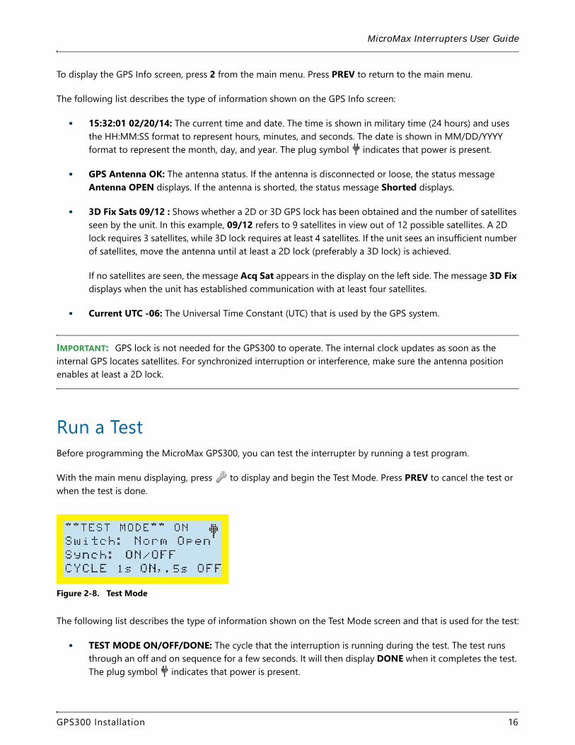
To display the GPS Info screen, press 2 from the main menu. Press PREV to return to the main menu.
The following list describes the type of information shown on the GPS Info screen:
• 15:32:01 02/20/14: The current time and date. The time is shown in military time (24 hours) and uses the HH:MM:SS format to represent hours, minutes, and seconds. The date is shown in MM/DD/YYYY format to represent the month, day, and year. The plug symbol indicates that power is present.
• GPS Antenna OK: The antenna status. If the antenna is disconnected or loose, the status message Antenna OPEN displays. If the antenna is shorted, the status message Shorted displays.
• 3D Fix Sats 09/12 : Shows whether a 2D or 3D GPS lock has been obtained and the number of satellites seen by the unit. In this example, 09/12 refers to 9 satellites in view out of 12 possible satellites. A 2D lock requires 3 satellites, while 3D lock requires at least 4 satellites. If the unit sees an insufficient number of satellites, move the antenna until at least a 2D lock (preferably a 3D lock) is achieved.
If no satellites are seen, the message Acq Sat appears in the display on the left side. The message 3D Fix displays when the unit has established communication with at least four satellites.
• Current UTC -06: The Universal Time Constant (UTC) that is used by the GPS system.
IMPORTANT: GPS lock is not needed for the GPS300 to operate. The internal clock updates as soon as the internal GPS locates satellites. For synchronized interruption or interference, make sure the antenna position enables at least a 2D lock.
Run a TestBefore programming the MicroMax GPS300, you can test the interrupter by running a test program.
With the main menu displaying, press to display and begin the Test Mode. Press PREV to cancel the test or when the test is done.
Figure 2-8. Test Mode
The following list describes the type of information shown on the Test Mode screen and that is used for the test:
• TEST MODE ON/OFF/DONE: The cycle that the interruption is running during the test. The test runs through an off and on sequence for a few seconds. It will then display DONE when it completes the test. The plug symbol indicates that power is present.
GPS300 Installation 16
MicroMax Interrupters User Guide
• Switch: Norm Open: Shows whether the relay is normally open or normally closed. The setting is determined by the Switch setting in Out Parameters (see Output Parameters).
• Synch: Shows that synchronization begins with On. The setting is determined by the Int. Cycle setting in Out Parameters (see Output Parameters).
• CYCLE 1s ON, .5s OFF: The timing of the on and off cycle.
Work with Other Brands of InterruptersThe GPS300 interrupter will work with most GPS-synchronized interrupters on the market. Most manufacturers use the same principle of calculating interruption synchronization.
Use the following procedure to synchronize a JR-2 interrupter with the GPS300 interrupter. The following procedure uses the optional, JR-2 adapter cable provided by AI.
1 Connect the JR-2 adapter cable to the JR-2 interrupter. Connect the other end of the adapter cable to the relay control output cable provided in the installation kit. Do not connect the banana plugs on the other end of the relay control output cable at this time.
2 Start the GPS300 interrupter with the following output parameters and interruption settings:
– Switch: Normally Closed (Low output = Off)
– Int. Cycle: OFF/ON
– On = 59.5; Off = 0.5
3 After the GPS300 interrupter has started interruption, use the exact time of the GPS300 as a guide when setting the JR-2 interrupter. Set the time ahead on the JR-2 interrupter to allow enough time to finish the procedure.
4 Before the next OFF cycle on the GPS300 interrupter, connect the banana plugs on the JR-2 adapter cable to the INPUT connections on the GPS300 or GPS350 power / relay assembly cable. Wait until an OFF cycle has executed.
The power cable assembly for the GPS300 interrupter is typically used for the relay control output cable. Refer to Figure 2-3 on page 15 for location of INPUT.
5 The interrupters should now be synchronized (clocks are set at the exact same time), and the GPS300 interrupter can be set back to the required program.
GPS300 Installation 17
GPS350 Installation 3
The MicroMax GPS350 interrupter consumes approximately 120 mA. The built-in solid state relay current consumption is additional 100 V / 80 A max with > 4 s cycle or 100 V / 60 A max with 1 s-4 s cycle. The relay is normally closed.
Install the GPS350 InterrupterWhen completing the following procedure, refer to the section entitled Supplied Cables for input and output voltage specifications.
WARNING: Make sure to follow all precautions when working with the interrupter and high voltage circuits.
WARNING: Do not connect the MicroMax GPS350 to primary power.
Caution: Metal relay casing on the MicroMax GPS350 will get hot. Allow 5 - 10 minutes after interruption stops before handling the unit.
Complete the following steps:
1 Determine how to power the MicroMax GPS350 using one of three possible sources (refer to Figure 3-1):
a Rectifier - with power turned on to the rectifier, use a voltmeter to locate a power source across two available AC taps. The MicroMax GPS350 requires 8-42 V AC or 10-60 V DC.
b A 120 V AC convenience outlet to use with the 12 V DC wall adapter.
c A DC source, such as a 10-60 V DC battery.
18
MicroMax Interrupters User Guide
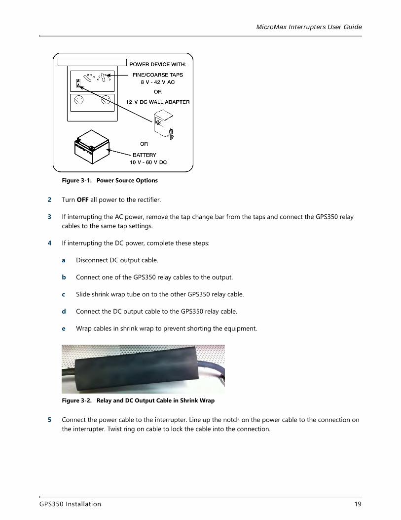
Figure 3-1. Power Source Options
2 Turn OFF all power to the rectifier.
3 If interrupting the AC power, remove the tap change bar from the taps and connect the GPS350 relay cables to the same tap settings.
4 If interrupting the DC power, complete these steps:
a Disconnect DC output cable.
b Connect one of the GPS350 relay cables to the output.
c Slide shrink wrap tube on to the other GPS350 relay cable.
d Connect the DC output cable to the GPS350 relay cable.
e Wrap cables in shrink wrap to prevent shorting the equipment.
Figure 3-2. Relay and DC Output Cable in Shrink Wrap
5 Connect the power cable to the interrupter. Line up the notch on the power cable to the connection on the interrupter. Twist ring on cable to lock the cable into the connection.
GPS350 Installation 19
MicroMax Interrupters User Guide
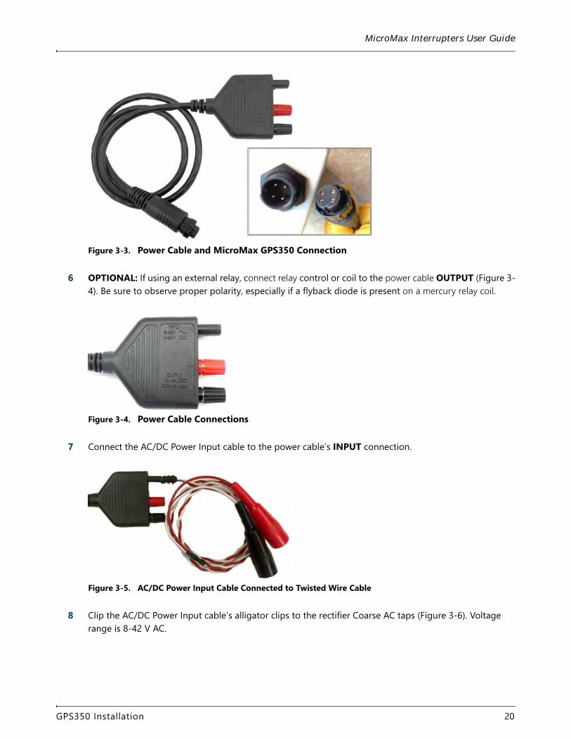
Figure 3-3. Power Cable and MicroMax GPS350 Connection
6 OPTIONAL: If using an external relay, connect relay control or coil to the power cable OUTPUT (Figure 3-4). Be sure to observe proper polarity, especially if a flyback diode is present on a mercury relay coil.
Figure 3-4. Power Cable Connections
7 Connect the AC/DC Power Input cable to the power cable’s INPUT connection.
Figure 3-5. AC/DC Power Input Cable Connected to Twisted Wire Cable
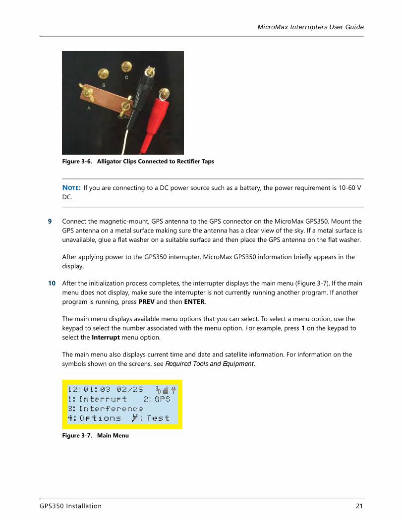
8 Clip the AC/DC Power Input cable’s alligator clips to the rectifier Coarse AC taps (Figure 3-6). Voltage range is 8-42 V AC.
GPS350 Installation 20
MicroMax Interrupters User Guide
Figure 3-6. Alligator Clips Connected to Rectifier Taps
NOTE: If you are connecting to a DC power source such as a battery, the power requirement is 10-60 V DC.
9 Connect the magnetic-mount, GPS antenna to the GPS connector on the MicroMax GPS350. Mount the GPS antenna on a metal surface making sure the antenna has a clear view of the sky. If a metal surface is unavailable, glue a flat washer on a suitable surface and then place the GPS antenna on the flat washer.
After applying power to the GPS350 interrupter, MicroMax GPS350 information briefly appears in the display.
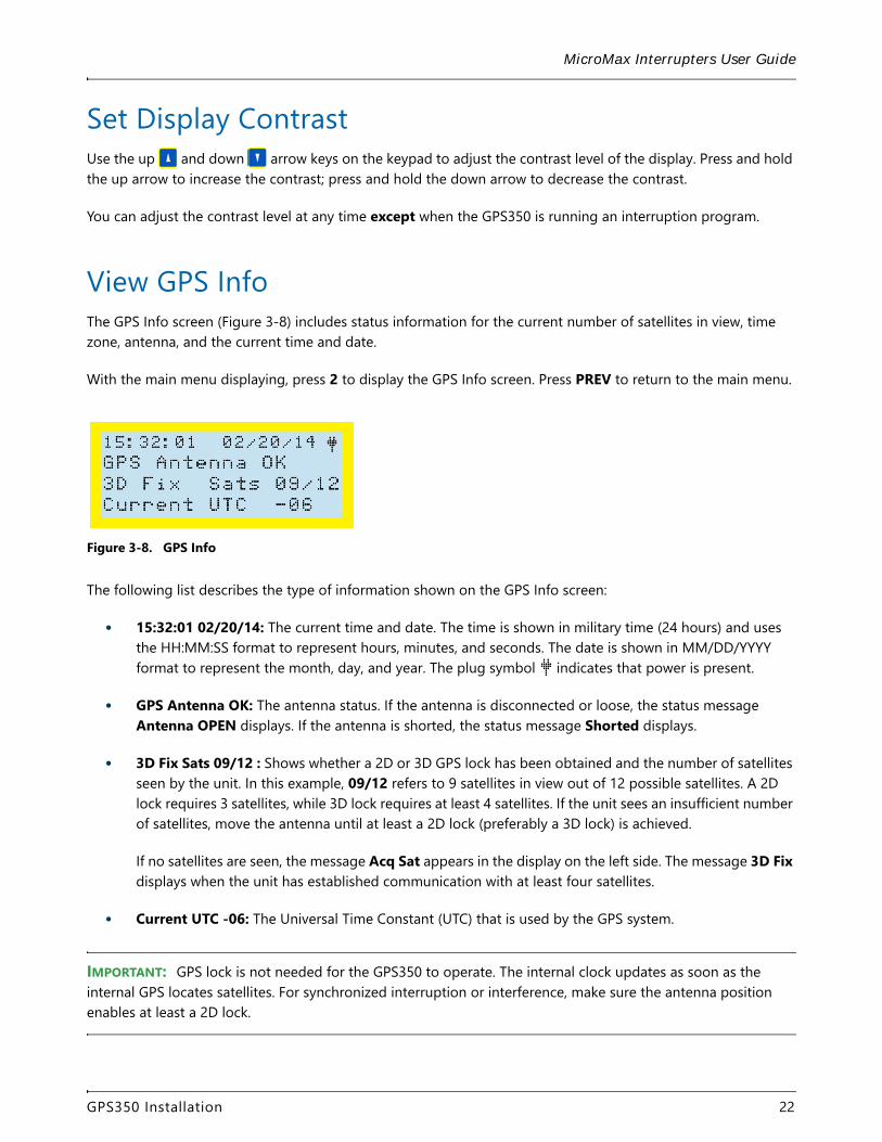
10 After the initialization process completes, the interrupter displays the main menu (Figure 3-7). If the main menu does not display, make sure the interrupter is not currently running another program. If another program is running, press PREV and then ENTER.
The main menu displays available menu options that you can select. To select a menu option, use the keypad to select the number associated with the menu option. For example, press 1 on the keypad to select the Interrupt menu option.
The main menu also displays current time and date and satellite information. For information on the symbols shown on the screens, see Required Tools and Equipment.
Figure 3-7. Main Menu
GPS350 Installation 21
MicroMax Interrupters User Guide
Set Display ContrastUse the up and down arrow keys on the keypad to adjust the contrast level of the display. Press and hold the up arrow to increase the contrast; press and hold the down arrow to decrease the contrast.
You can adjust the contrast level at any time except when the GPS350 is running an interruption program.
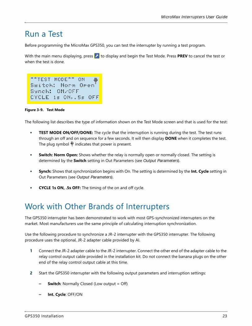
View GPS InfoThe GPS Info screen (Figure 3-8) includes status information for the current number of satellites in view, time zone, antenna, and the current time and date.
With the main menu displaying, press 2 to display the GPS Info screen. Press PREV to return to the main menu.
Figure 3-8. GPS Info
The following list describes the type of information shown on the GPS Info screen:
• 15:32:01 02/20/14: The current time and date. The time is shown in military time (24 hours) and uses the HH:MM:SS format to represent hours, minutes, and seconds. The date is shown in MM/DD/YYYY format to represent the month, day, and year. The plug symbol indicates that power is present.
• GPS Antenna OK: The antenna status. If the antenna is disconnected or loose, the status message Antenna OPEN displays. If the antenna is shorted, the status message Shorted displays.
• 3D Fix Sats 09/12 : Shows whether a 2D or 3D GPS lock has been obtained and the number of satellites seen by the unit. In this example, 09/12 refers to 9 satellites in view out of 12 possible satellites. A 2D lock requires 3 satellites, while 3D lock requires at least 4 satellites. If the unit sees an insufficient number of satellites, move the antenna until at least a 2D lock (preferably a 3D lock) is achieved.
If no satellites are seen, the message Acq Sat appears in the display on the left side. The message 3D Fix displays when the unit has established communication with at least four satellites.
• Current UTC -06: The Universal Time Constant (UTC) that is used by the GPS system.
IMPORTANT: GPS lock is not needed for the GPS350 to operate. The internal clock updates as soon as the internal GPS locates satellites. For synchronized interruption or interference, make sure the antenna position enables at least a 2D lock.
GPS350 Installation 22
MicroMax Interrupters User Guide
Run a TestBefore programming the MicroMax GPS350, you can test the interrupter by running a test program.
With the main menu displaying, press to display and begin the Test Mode. Press PREV to cancel the test or when the test is done.
Figure 3-9. Test Mode
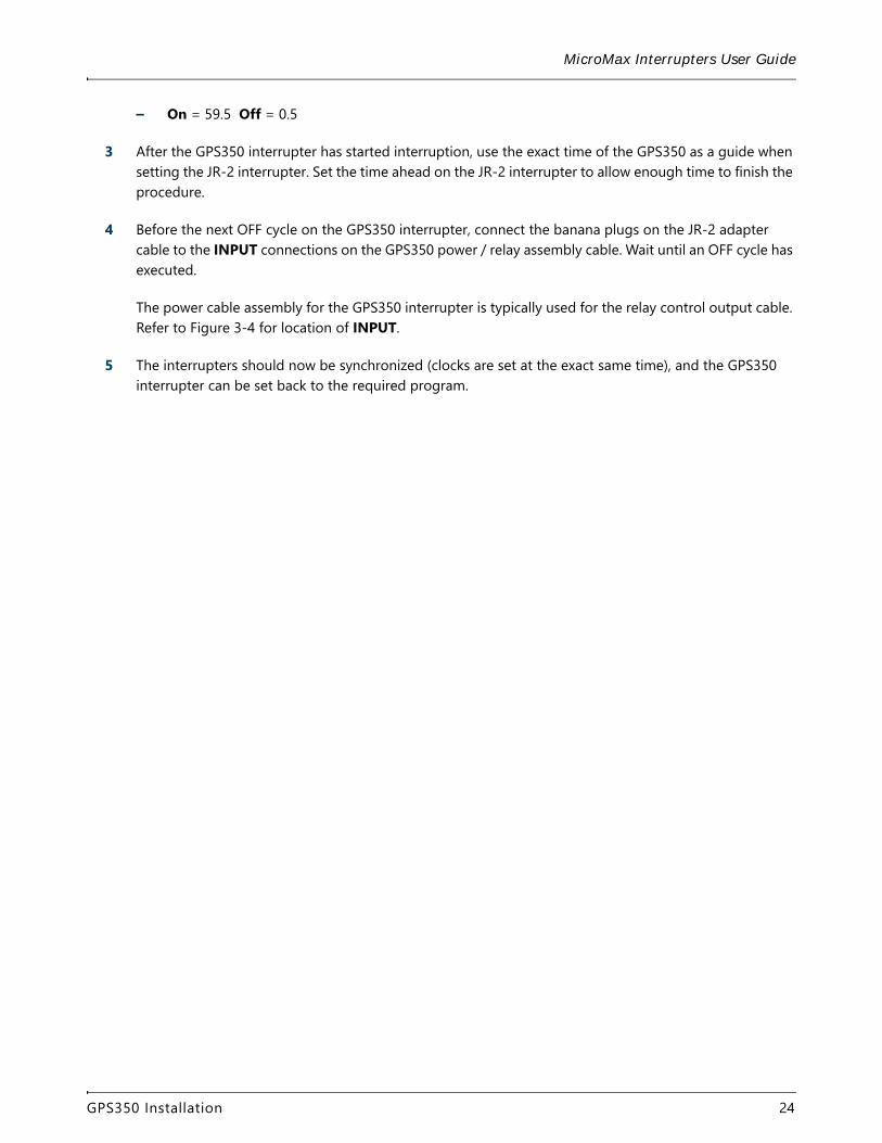
The following list describes the type of information shown on the Test Mode screen and that is used for the test:
• TEST MODE ON/OFF/DONE: The cycle that the interruption is running during the test. The test runs through an off and on sequence for a few seconds. It will then display DONE when it completes the test. The plug symbol indicates that power is present.
• Switch: Norm Open: Shows whether the relay is normally open or normally closed. The setting is determined by the Switch setting in Out Parameters (see Output Parameters).
• Synch: Shows that synchronization begins with On. The setting is determined by the Int. Cycle setting in Out Parameters (see Output Parameters).
• CYCLE 1s ON, .5s OFF: The timing of the on and off cycle.
Work with Other Brands of InterruptersThe GPS350 interrupter has been demonstrated to work with most GPS-synchronized interrupters on the market. Most manufacturers use the same principle of calculating interruption synchronization.
Use the following procedure to synchronize a JR-2 interrupter with the GPS350 interrupter. The following procedure uses the optional, JR-2 adapter cable provided by AI.
1 Connect the JR-2 adapter cable to the JR-2 interrupter. Connect the other end of the adapter cable to the relay control output cable provided in the installation kit. Do not connect the banana plugs on the other end of the relay control output cable at this time.
2 Start the GPS350 interrupter with the following output parameters and interruption settings:
– Switch: Normally Closed (Low output = Off)
– Int. Cycle: OFF/ON
GPS350 Installation 23
MicroMax Interrupters User Guide
– On = 59.5 Off = 0.5
3 After the GPS350 interrupter has started interruption, use the exact time of the GPS350 as a guide when setting the JR-2 interrupter. Set the time ahead on the JR-2 interrupter to allow enough time to finish the procedure.
4 Before the next OFF cycle on the GPS350 interrupter, connect the banana plugs on the JR-2 adapter cable to the INPUT connections on the GPS350 power / relay assembly cable. Wait until an OFF cycle has executed.
The power cable assembly for the GPS350 interrupter is typically used for the relay control output cable. Refer to Figure 3-4 for location of INPUT.
5 The interrupters should now be synchronized (clocks are set at the exact same time), and the GPS350 interrupter can be set back to the required program.
GPS350 Installation 24
Configuration 4
The MicroMax GPS300 and GPS350 interrupters can be programed either manually by using the unit’s keypad or with the Bullhorn Tools configuration software. Refer to Configuration and Support Software for more information on loading the configuration software tools.
For manual programming, begin with Configure with Unit Keypad.
For instructions on using Bullhorn Tools to configure the interruption and interference programs, see Configure with Bullhorn Tools.
Configure with Unit KeypadThe MicroMax GPS300 and GPS350 interrupters can be set up through keypad menus and buttons. The following set-up tasks can be done from the keypad on the unit:
• Set Up and Run an Interruption Program – set up to 9 different interruption programs.
• Set Up an Interference Interruption Program – set up or run an interference interruption program.
• Options Features – set other features of the interrupters, including Output Parameters, UTC Offset, Zero Crossing, and Zero Crossing.
Set Up and Run an Interruption ProgramComplete the following steps to setup and run an interruption program from the MicroMax GPS300 or GPS350 keypad:
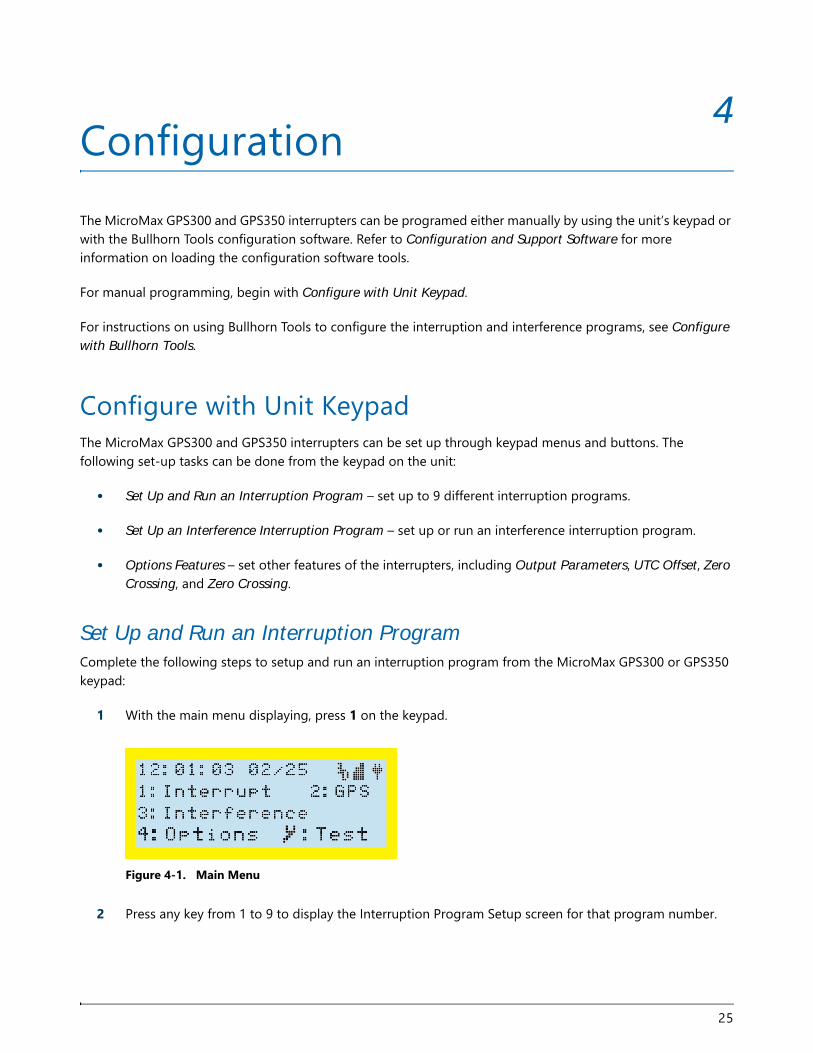
1 With the main menu displaying, press 1 on the keypad.
Figure 4-1. Main Menu
2 Press any key from 1 to 9 to display the Interruption Program Setup screen for that program number.
25
MicroMax Interrupters User Guide
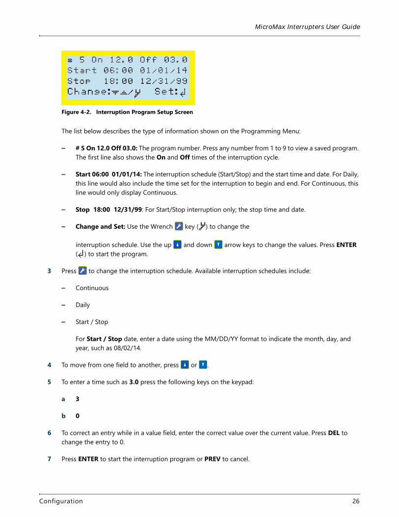
Figure 4-2. Interruption Program Setup Screen
The list below describes the type of information shown on the Programming Menu:
– # 5 On 12.0 Off 03.0: The program number. Press any number from 1 to 9 to view a saved program. The first line also shows the On and Off times of the interruption cycle.
– Start 06:00 01/01/14: The interruption schedule (Start/Stop) and the start time and date. For Daily, this line would also include the time set for the interruption to begin and end. For Continuous, this line would only display Continuous.
– Stop 18:00 12/31/99: For Start/Stop interruption only; the stop time and date.
– Change and Set: Use the Wrench key ( ) to change theinterruption schedule. Use the up and down arrow keys to change the values. Press ENTER ( ) to start the program.
3 Press to change the interruption schedule. Available interruption schedules include:
– Continuous
– Daily
– Start / Stop
For Start / Stop date, enter a date using the MM/DD/YY format to indicate the month, day, and year, such as 08/02/14.
4 To move from one field to another, press or .
5 To enter a time such as 3.0 press the following keys on the keypad:
a 3
b 0
6 To correct an entry while in a value field, enter the correct value over the current value. Press DEL to change the entry to 0.
7 Press ENTER to start the interruption program or PREV to cancel.
Configuration 26
MicroMax Interrupters User Guide
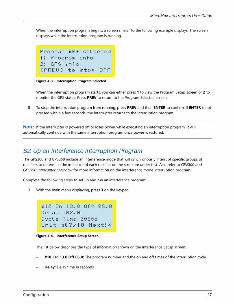
When the interruption program begins, a screen similar to the following example displays. The screen displays while the interruption program is running.
Figure 4-3. Interruption Program Selected
When the interruption program starts, you can either press 1 to view the Program Setup screen or 2 to monitor the GPS status. Press PREV to return to the Program Selected screen.
8 To stop the interruption program from running, press PREV and then ENTER to confirm. If ENTER is not pressed within a few seconds, the interrupter returns to the interruption program.
NOTE: If the interrupter is powered off or loses power while executing an interruption program, it will automatically continue with the same interruption program once power is restored.
Set Up an Interference Interruption ProgramThe GPS300 and GPS350 include an interference mode that will synchronously interrupt specific groups of rectifiers to determine the influence of each rectifier on the structure under test. Also refer to GPS300 and GPS350 Interrupter Overview for more information on the interference mode interruption program.
Complete the following steps to set up and run an interference program:
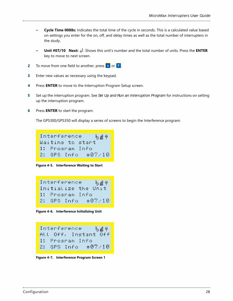
1 With the main menu displaying, press 3 on the keypad.
Figure 4-4. Interference Setup Screen
The list below describes the type of information shown on the Interference Setup screen:
– #10 On 13.0 Off 05.0: The program number and the on and off times of the interruption cycle.
– Delay: Delay time in seconds.
Configuration 27
MicroMax Interrupters User Guide
– Cycle Time 0088s: Indicates the total time of the cycle in seconds. This is a calculated value based on settings you enter for the on, off, and delay times as well as the total number of interrupters in the study.
– Unit #07/10 Next: : Shows this unit’s number and the total number of units. Press the ENTER key to move to next screen.
2 To move from one field to another, press or .
3 Enter new values as necessary using the keypad.
4 Press ENTER to move to the Interruption Program Setup screen.
5 Set up the interruption program. See Set Up and Run an Interruption Program for instructions on setting up the interruption program.
6 Press ENTER to start the program.
The GPS300/GPS350 will display a series of screens to begin the Interference program:
Figure 4-5. Interference Waiting to Start
Figure 4-6. Interference Initializing Unit
Figure 4-7. Interference Program Screen 1
Configuration 28

MicroMax Interrupters User Guide
Figure 4-8. Interference Program Screen 2
The program then cycles through the set number of units shown at the bottom of the screen (For example, 10 as shown in this example). When finished, the program begins again.
Figure 4-9. Interference Program Screen 3
7 To cancel the program, press PREV. A cancellation confirmation screen displays.
Figure 4-10. Cancellation Confirmation Screen
8 Press ENTER to cancel and return to main menu. If you do not press ENTER within a few seconds, the program will continue.
Options FeaturesOther features, such as setting output parameters, changing UTC offset, using zero crossing, and restoring factory defaults, are completed using the Options menu.
To display the Options menu:
1 With the main menu displaying, press 4 on the keypad to display the Options menu.
Configuration 29
MicroMax Interrupters User Guide
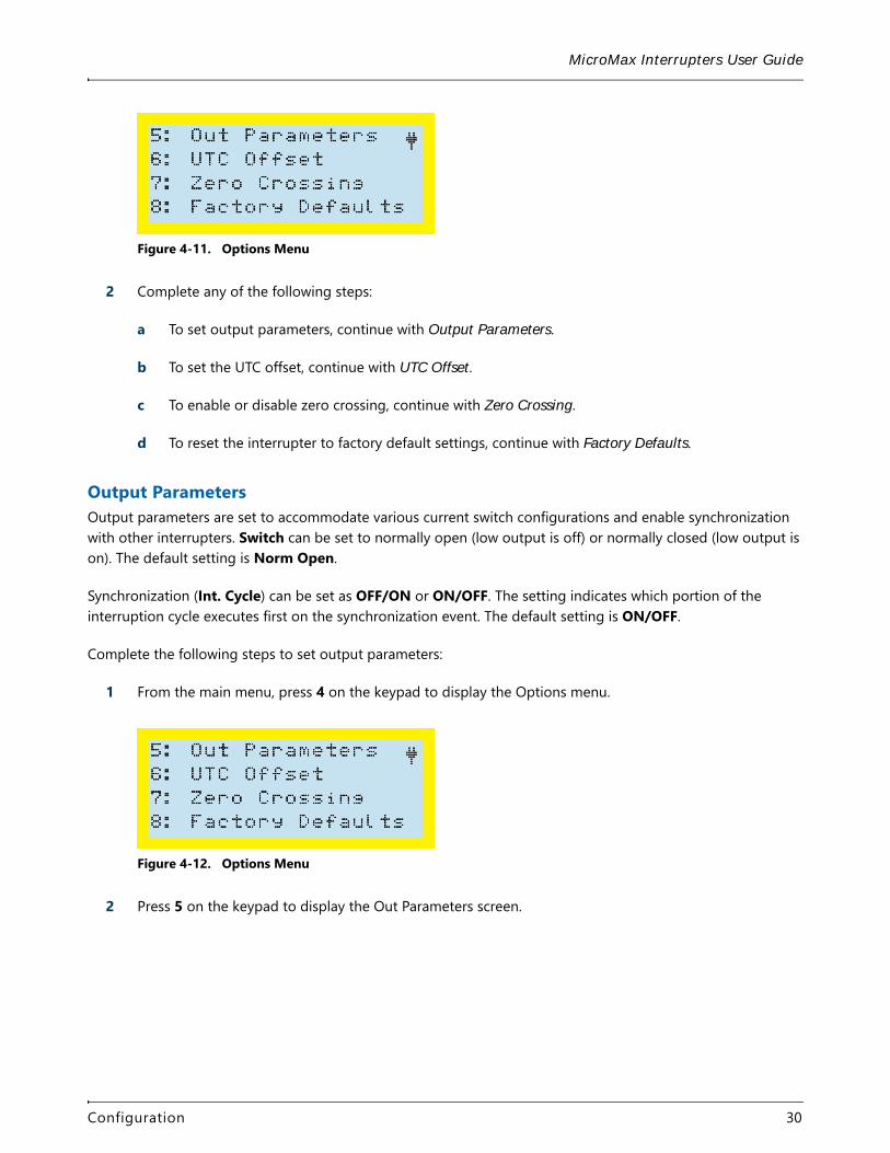
Figure 4-11. Options Menu
2 Complete any of the following steps:
a To set output parameters, continue with Output Parameters.
b To set the UTC offset, continue with UTC Offset.
c To enable or disable zero crossing, continue with Zero Crossing.
d To reset the interrupter to factory default settings, continue with Factory Defaults.
Output ParametersOutput parameters are set to accommodate various current switch configurations and enable synchronization with other interrupters. Switch can be set to normally open (low output is off) or normally closed (low output is on). The default setting is Norm Open.
Synchronization (Int. Cycle) can be set as OFF/ON or ON/OFF. The setting indicates which portion of the interruption cycle executes first on the synchronization event. The default setting is ON/OFF.
Complete the following steps to set output parameters:
1 From the main menu, press 4 on the keypad to display the Options menu.
Figure 4-12. Options Menu
2 Press 5 on the keypad to display the Out Parameters screen.
Configuration 30
MicroMax Interrupters User Guide
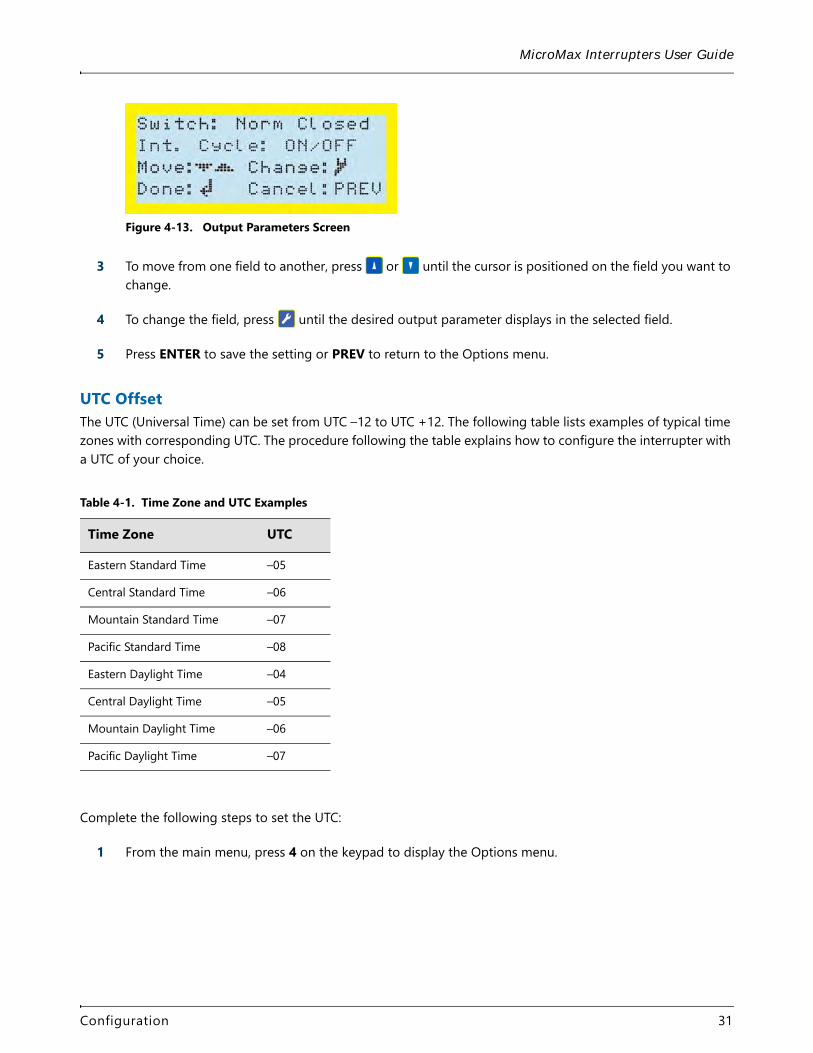
Figure 4-13. Output Parameters Screen
3 To move from one field to another, press or until the cursor is positioned on the field you want to change.
4 To change the field, press until the desired output parameter displays in the selected field.
5 Press ENTER to save the setting or PREV to return to the Options menu.
UTC OffsetThe UTC (Universal Time) can be set from UTC –12 to UTC +12. The following table lists examples of typical time zones with corresponding UTC. The procedure following the table explains how to configure the interrupter with a UTC of your choice.
Complete the following steps to set the UTC:
1 From the main menu, press 4 on the keypad to display the Options menu.
Table 4-1. Time Zone and UTC Examples
Time Zone UTC
Eastern Standard Time –05
Central Standard Time –06
Mountain Standard Time –07
Pacific Standard Time –08
Eastern Daylight Time –04
Central Daylight Time –05
Mountain Daylight Time –06
Pacific Daylight Time –07
Configuration 31
MicroMax Interrupters User Guide
Figure 4-14. Options Menu
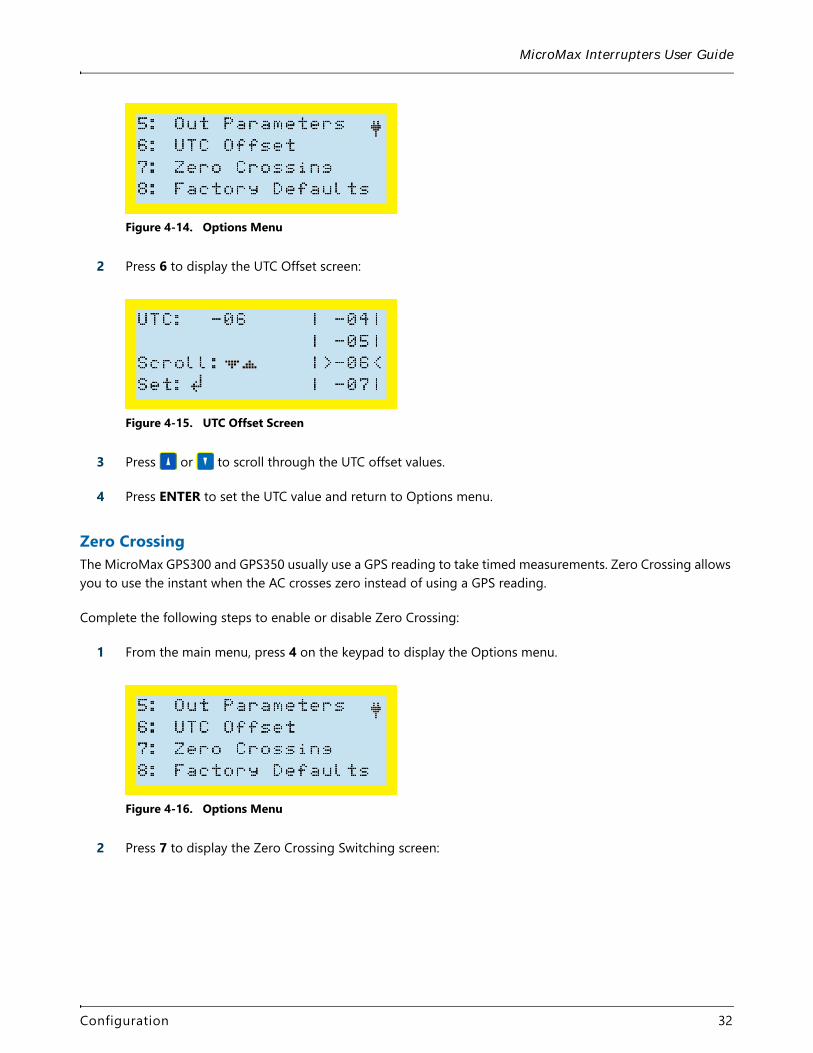
2 Press 6 to display the UTC Offset screen:
Figure 4-15. UTC Offset Screen
3 Press or to scroll through the UTC offset values.
4 Press ENTER to set the UTC value and return to Options menu.
Zero CrossingThe MicroMax GPS300 and GPS350 usually use a GPS reading to take timed measurements. Zero Crossing allows you to use the instant when the AC crosses zero instead of using a GPS reading.
Complete the following steps to enable or disable Zero Crossing:
1 From the main menu, press 4 on the keypad to display the Options menu.
Figure 4-16. Options Menu
2 Press 7 to display the Zero Crossing Switching screen:
Configuration 32
MicroMax Interrupters User Guide
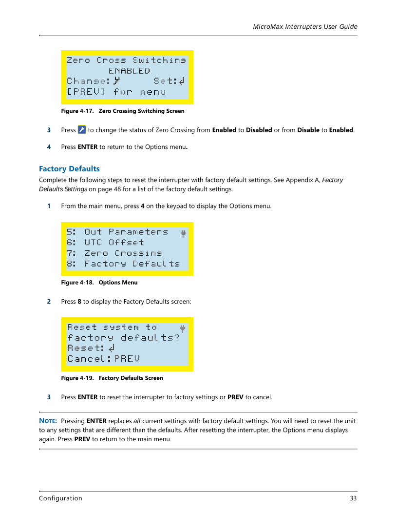
Figure 4-17. Zero Crossing Switching Screen
3 Press to change the status of Zero Crossing from Enabled to Disabled or from Disable to Enabled.
4 Press ENTER to return to the Options menu.
Factory DefaultsComplete the following steps to reset the interrupter with factory default settings. See Appendix A, Factory Defaults Settings on page 48 for a list of the factory default settings.
1 From the main menu, press 4 on the keypad to display the Options menu.
Figure 4-18. Options Menu
2 Press 8 to display the Factory Defaults screen:
Figure 4-19. Factory Defaults Screen
3 Press ENTER to reset the interrupter to factory settings or PREV to cancel.
NOTE: Pressing ENTER replaces all current settings with factory default settings. You will need to reset the unit to any settings that are different than the defaults. After resetting the interrupter, the Options menu displays again. Press PREV to return to the main menu.
Configuration 33
MicroMax Interrupters User Guide
Configure with Bullhorn ToolsBullhorn Tools is the configuration software that can be used to program a MicroMax GPS300 or GPS350 interrupter. The software is available for download from your Bullhorn Web account (Help > Downloads).
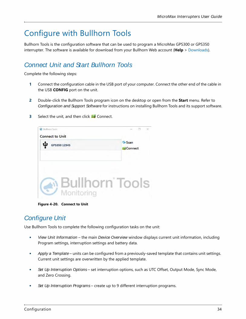
Connect Unit and Start Bullhorn ToolsComplete the following steps:
1 Connect the configuration cable in the USB port of your computer. Connect the other end of the cable in the USB CONFIG port on the unit.
2 Double-click the Bullhorn Tools program icon on the desktop or open from the Start menu. Refer to Configuration and Support Software for instructions on installing Bullhorn Tools and its support software.
3 Select the unit, and then click Connect.
Figure 4-20. Connect to Unit
Configure UnitUse Bullhorn Tools to complete the following configuration tasks on the unit:
• View Unit Information – the main Device Overview window displays current unit information, including Program settings, interruption settings and battery data.
• Apply a Template – units can be configured from a previously-saved template that contains unit settings. Current unit settings are overwritten by the applied template.
• Set Up Interruption Options – set interruption options, such as UTC Offset, Output Mode, Sync Mode, and Zero Crossing.
• Set Up Interruption Programs – create up to 9 different interruption programs.
Configuration 34
MicroMax Interrupters User Guide
• Set Up an Interference Interruption Program – set up interference mode with interruption.
• Work with Templates – unit settings can be saved to a template to save time when configuring multiple, identical units. Saved templates can be exported or deleted.
• Reset to Factory Defaults – resets the unit to settings that were made during manufacturing.
• Upgrade Firmware – when available, the unit firmware can be upgraded.
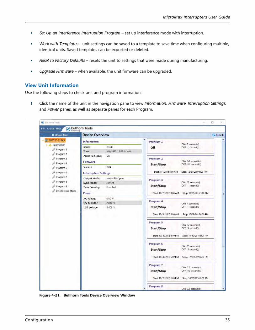
View Unit InformationUse the following steps to check unit and program information:
1 Click the name of the unit in the navigation pane to view Information, Firmware, Interruption Settings, and Power panes, as well as separate panes for each Program.
.
Figure 4-21. Bullhorn Tools Device Overview Window
Configuration 35
MicroMax Interrupters User Guide
2 Click Refresh to read unit settings and verify the unit and Bullhorn Tools software are communicating.
Apply a TemplateIf a template is available for the unit type you plan to configure, you can apply the template to the current unit. You can also import a saved template to Bullhorn Tools and then apply it to the current unit.
For information on how to export or delete a saved template, refer to Work with Templates.
Complete the following steps to import a saved template (optional) and then apply a template to the unit (starting with step 5):
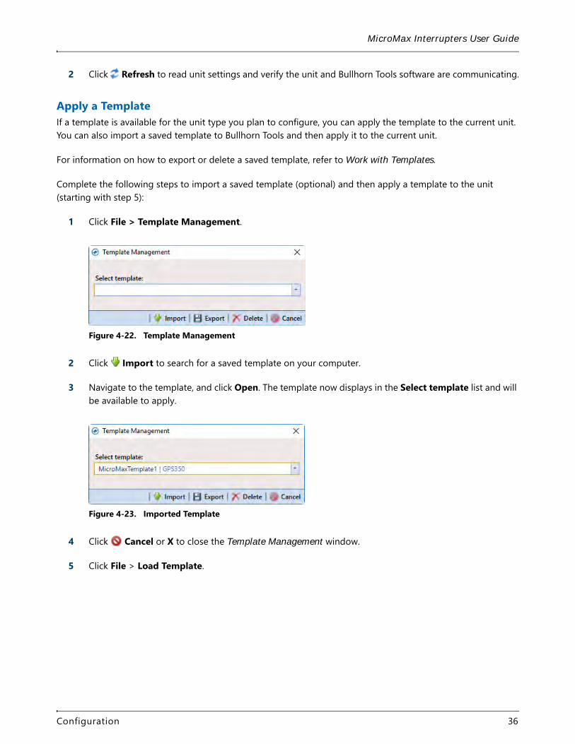
1 Click File > Template Management.
Figure 4-22. Template Management
2 Click Import to search for a saved template on your computer.
3 Navigate to the template, and click Open. The template now displays in the Select template list and will be available to apply.
Figure 4-23. Imported Template
4 Click Cancel or X to close the Template Management window.
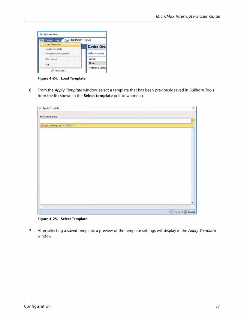
5 Click File > Load Template.
Configuration 36
MicroMax Interrupters User Guide
Figure 4-24. Load Template
6 From the Apply Template window, select a template that has been previously saved in Bullhorn Tools from the list shown in the Select template pull-down menu.
Figure 4-25. Select Template
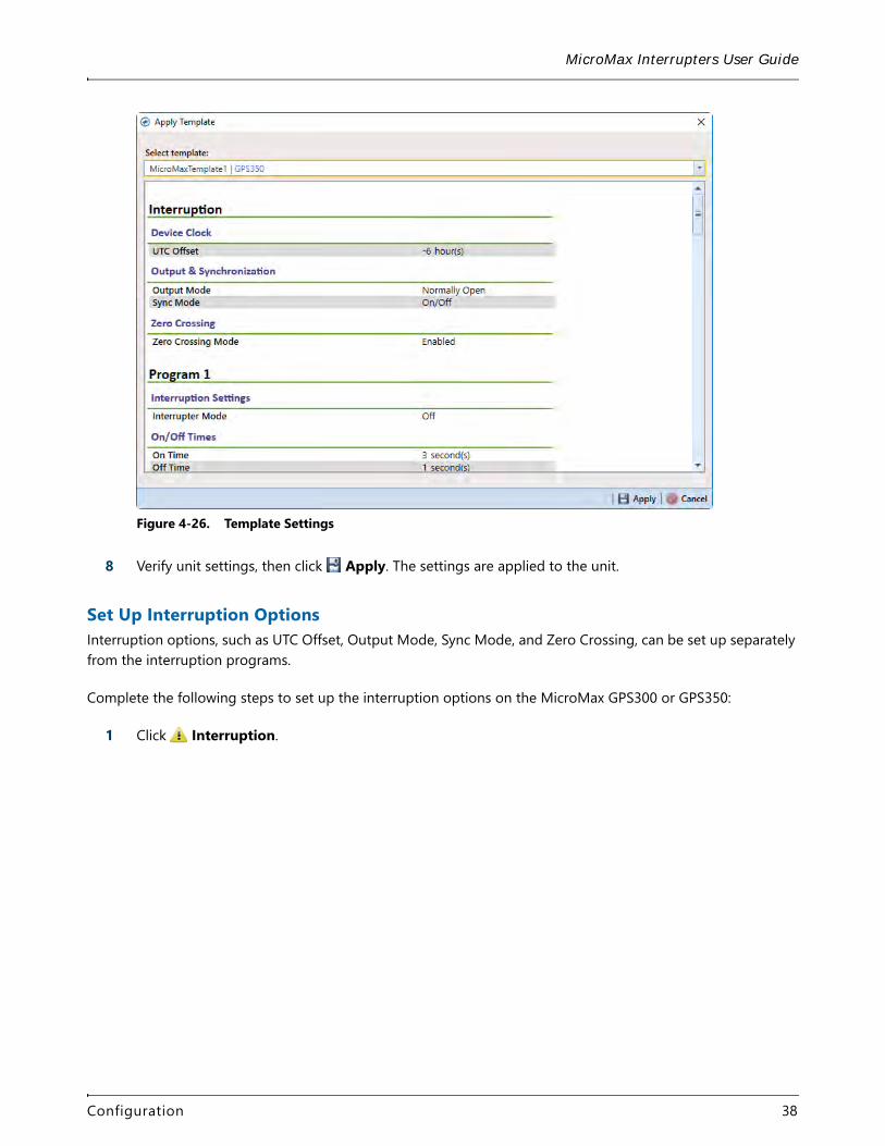
7 After selecting a saved template, a preview of the template settings will display in the Apply Template window.
Configuration 37
MicroMax Interrupters User Guide
Figure 4-26. Template Settings
8 Verify unit settings, then click Apply. The settings are applied to the unit.
Set Up Interruption OptionsInterruption options, such as UTC Offset, Output Mode, Sync Mode, and Zero Crossing, can be set up separately from the interruption programs.
Complete the following steps to set up the interruption options on the MicroMax GPS300 or GPS350:
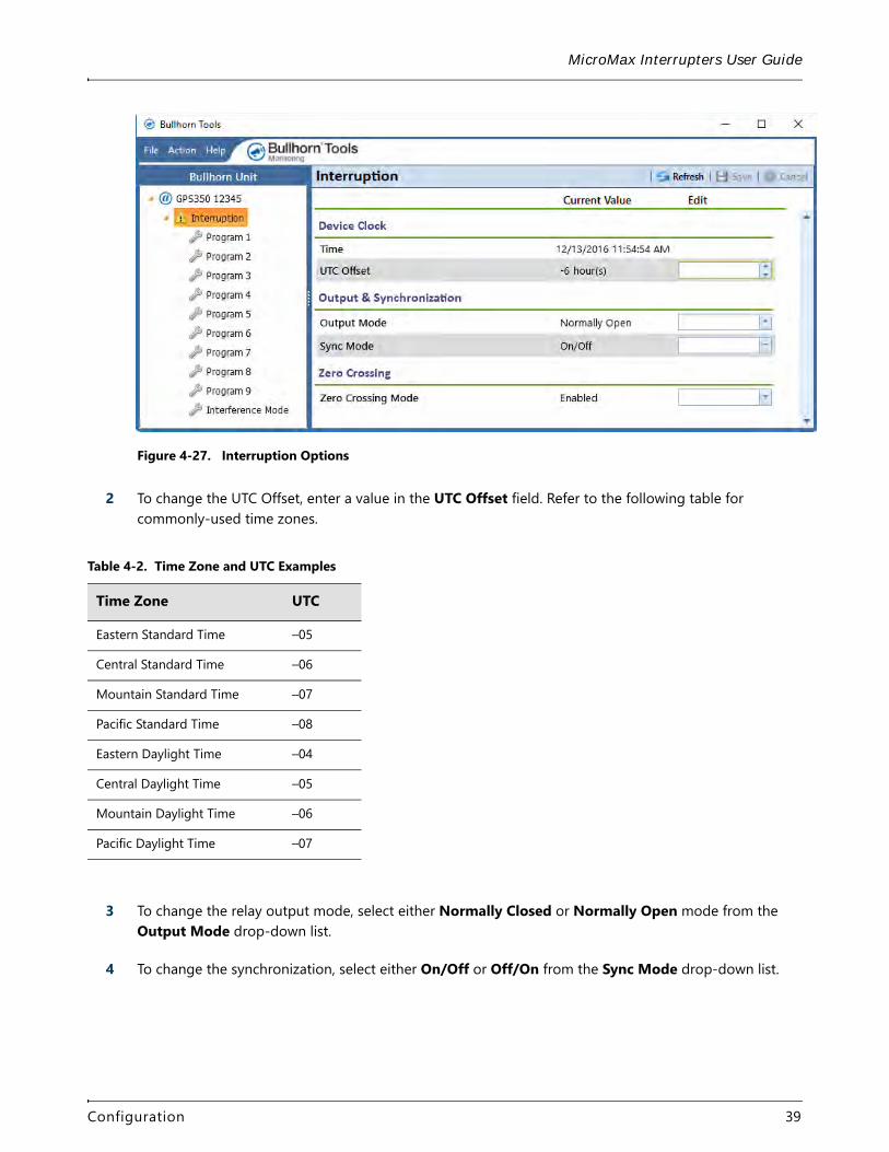
1 Click Interruption.
Configuration 38
MicroMax Interrupters User Guide
Figure 4-27. Interruption Options
2 To change the UTC Offset, enter a value in the UTC Offset field. Refer to the following table for commonly-used time zones.
3 To change the relay output mode, select either Normally Closed or Normally Open mode from the Output Mode drop-down list.
4 To change the synchronization, select either On/Off or Off/On from the Sync Mode drop-down list.
Table 4-2. Time Zone and UTC Examples
Time Zone UTC
Eastern Standard Time –05
Central Standard Time –06
Mountain Standard Time –07
Pacific Standard Time –08
Eastern Daylight Time –04
Central Daylight Time –05
Mountain Daylight Time –06
Pacific Daylight Time –07
Configuration 39
MicroMax Interrupters User Guide
5 The MicroMax GPS300 and GPS350 usually use a GPS reading to take timed measurements. Zero Crossing allows you to use the instant when the AC crosses zero instead of using a GPS reading. To enable zero crossing for timed measurements, select Enabled from the Zero Crossing Mode drop-down list.
6 Click Save to save settings or Cancel to clear all fields.
Set Up Interruption ProgramsThe 9 interruption programs can be set up from the main Bullhorn Tools window.
Complete the following steps to set up Interruption Program 1 through Program 9:
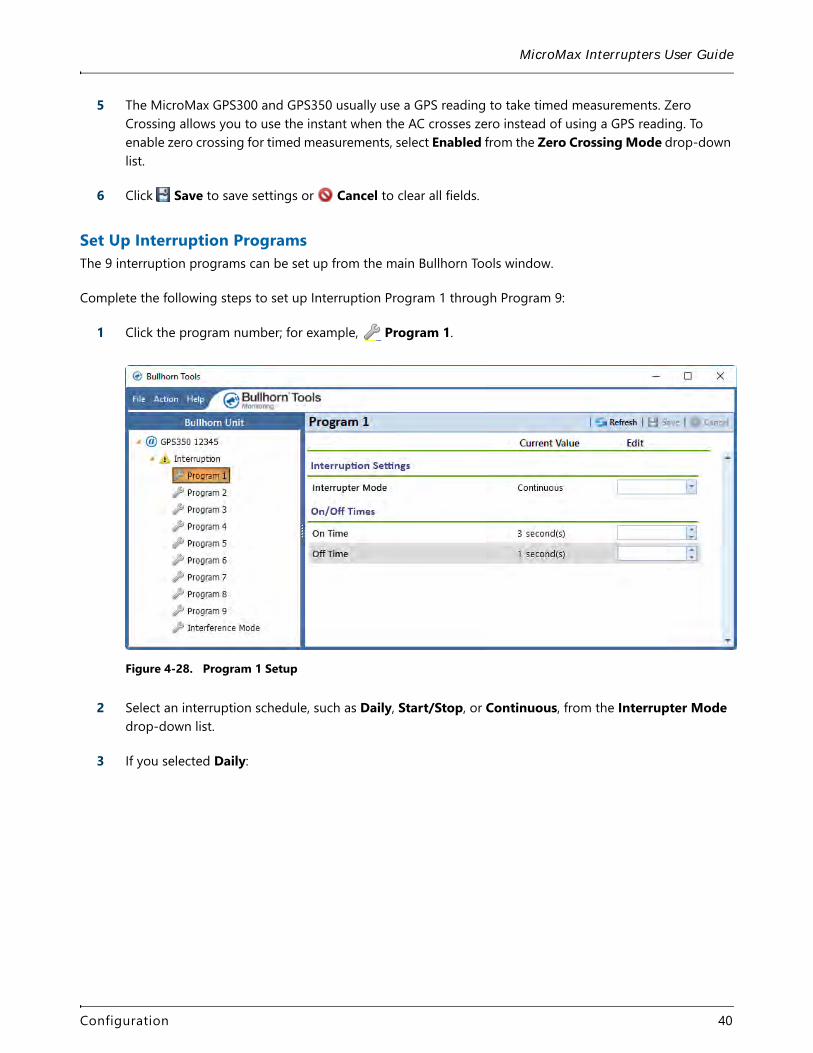
1 Click the program number; for example, Program 1.
Figure 4-28. Program 1 Setup
2 Select an interruption schedule, such as Daily, Start/Stop, or Continuous, from the Interrupter Mode drop-down list.
3 If you selected Daily:
Configuration 40
MicroMax Interrupters User Guide
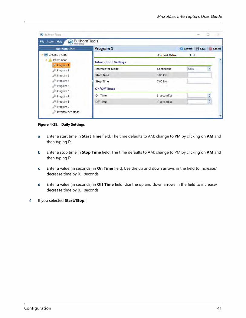
Figure 4-29. Daily Settings
a Enter a start time in Start Time field. The time defaults to AM; change to PM by clicking on AM and then typing P.
b Enter a stop time in Stop Time field. The time defaults to AM; change to PM by clicking on AM and then typing P.
c Enter a value (in seconds) in On Time field. Use the up and down arrows in the field to increase/decrease time by 0.1 seconds.
d Enter a value (in seconds) in Off Time field. Use the up and down arrows in the field to increase/decrease time by 0.1 seconds.
4 If you selected Start/Stop:
Configuration 41
MicroMax Interrupters User Guide
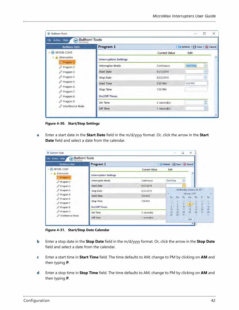
Figure 4-30. Start/Stop Settings
a Enter a start date in the Start Date field in the m/d/yyyy format. Or, click the arrow in the Start Date field and select a date from the calendar.
Figure 4-31. Start/Stop Date Calendar
b Enter a stop date in the Stop Date field in the m/d/yyyy format. Or, click the arrow in the Stop Date field and select a date from the calendar.
c Enter a start time in Start Time field. The time defaults to AM; change to PM by clicking on AM and then typing P.
d Enter a stop time in Stop Time field. The time defaults to AM; change to PM by clicking on AM and then typing P.
Configuration 42

MicroMax Interrupters User Guide
e Enter a value (in seconds) in On Time field. Use the up and down arrows in the field to increase/decrease time by 0.1 seconds.
f Enter a value (in seconds) in Off Time field. Use the up and down arrows in the field to increase/decrease time by 0.1 seconds.
5 If you selected Continuous:
Figure 4-32. Continuous Settings
a Enter a value, in seconds, in the On Time field. Use the up and down arrows in the field to increase/decrease time by 0.1 seconds.
b Enter a value, in seconds, in the Off Time field. Use the up and down arrows tin the field to increase/decrease time by 0.1 seconds.
6 Click Save to save settings or Cancel to clear all fields.
7 Repeat for each additional program.
Set Up an Interference Interruption ProgramThe GPS300 and GPS350 include an interference mode that will synchronously interrupt specific groups of rectifiers to determine the influence of each rectifier on the structure under test. Also refer to GPS300 and GPS350 Interrupter Overview for more information on the interference mode interruption program.
Complete the following steps to set up an Interference program:
1 Click Interference Mode.
Configuration 43
MicroMax Interrupters User Guide
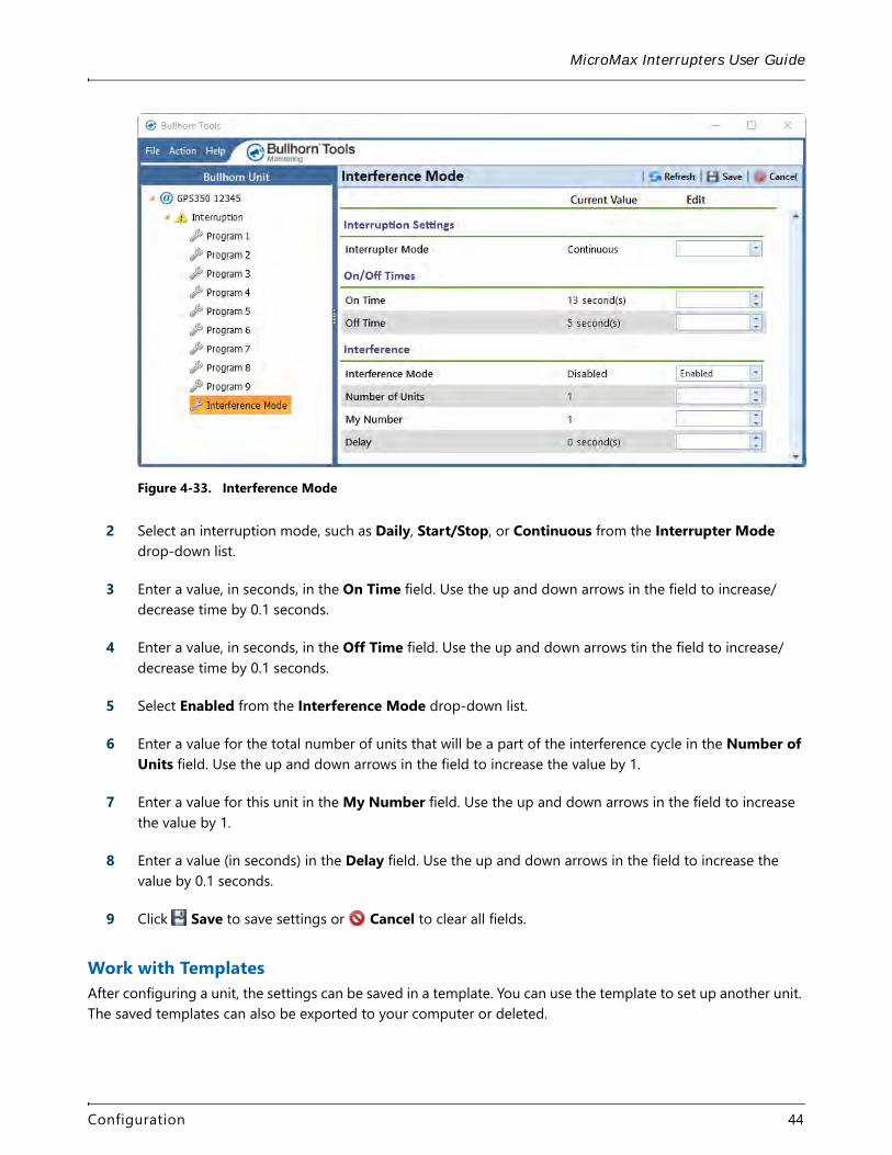
Figure 4-33. Interference Mode
2 Select an interruption mode, such as Daily, Start/Stop, or Continuous from the Interrupter Mode drop-down list.
3 Enter a value, in seconds, in the On Time field. Use the up and down arrows in the field to increase/decrease time by 0.1 seconds.
4 Enter a value, in seconds, in the Off Time field. Use the up and down arrows tin the field to increase/decrease time by 0.1 seconds.
5 Select Enabled from the Interference Mode drop-down list.
6 Enter a value for the total number of units that will be a part of the interference cycle in the Number of Units field. Use the up and down arrows in the field to increase the value by 1.
7 Enter a value for this unit in the My Number field. Use the up and down arrows in the field to increase the value by 1.
8 Enter a value (in seconds) in the Delay field. Use the up and down arrows in the field to increase the value by 0.1 seconds.
9 Click Save to save settings or Cancel to clear all fields.
Work with TemplatesAfter configuring a unit, the settings can be saved in a template. You can use the template to set up another unit. The saved templates can also be exported to your computer or deleted.
Configuration 44
MicroMax Interrupters User Guide
Complete the following steps to create a new template:
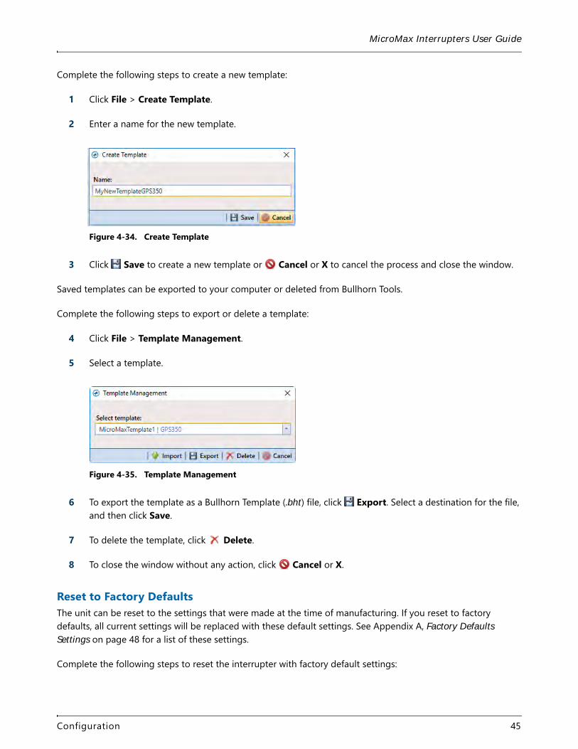
1 Click File > Create Template.
2 Enter a name for the new template.
Figure 4-34. Create Template
3 Click Save to create a new template or Cancel or X to cancel the process and close the window.
Saved templates can be exported to your computer or deleted from Bullhorn Tools.
Complete the following steps to export or delete a template:
4 Click File > Template Management.
5 Select a template.
Figure 4-35. Template Management
6 To export the template as a Bullhorn Template (.bht) file, click Export. Select a destination for the file, and then click Save.
7 To delete the template, click Delete.
8 To close the window without any action, click Cancel or X.
Reset to Factory DefaultsThe unit can be reset to the settings that were made at the time of manufacturing. If you reset to factory defaults, all current settings will be replaced with these default settings. See Appendix A, Factory Defaults Settings on page 48 for a list of these settings.
Complete the following steps to reset the interrupter with factory default settings:
Configuration 45
MicroMax Interrupters User Guide
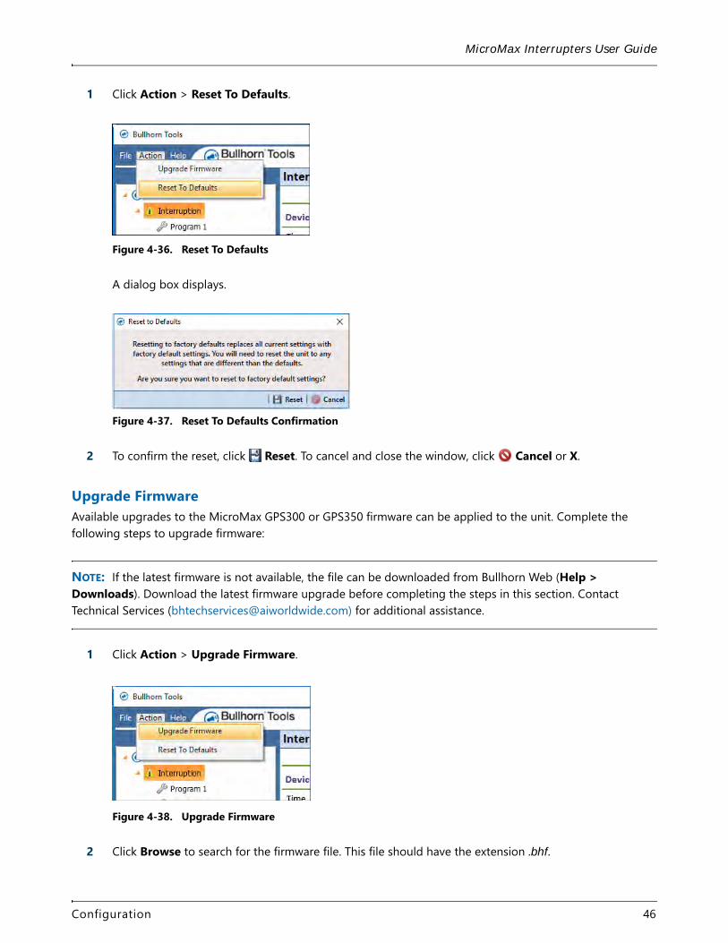
1 Click Action > Reset To Defaults.
Figure 4-36. Reset To Defaults
A dialog box displays.
Figure 4-37. Reset To Defaults Confirmation
2 To confirm the reset, click Reset. To cancel and close the window, click Cancel or X.
Upgrade FirmwareAvailable upgrades to the MicroMax GPS300 or GPS350 firmware can be applied to the unit. Complete the following steps to upgrade firmware:
NOTE: If the latest firmware is not available, the file can be downloaded from Bullhorn Web (Help > Downloads). Download the latest firmware upgrade before completing the steps in this section. Contact Technical Services ([email protected]) for additional assistance.
1 Click Action > Upgrade Firmware.
Figure 4-38. Upgrade Firmware
2 Click Browse to search for the firmware file. This file should have the extension .bhf.
Configuration 46
MicroMax Interrupters User Guide
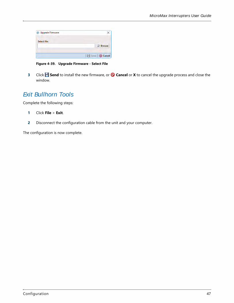
Figure 4-39. Upgrade Firmware - Select File
3 Click Send to install the new firmware, or Cancel or X to cancel the upgrade process and close the window.
Exit Bullhorn ToolsComplete the following steps:
1 Click File > Exit.
2 Disconnect the configuration cable from the unit and your computer.
The configuration is now complete.
Configuration 47
48
Factory Defaults Settings A
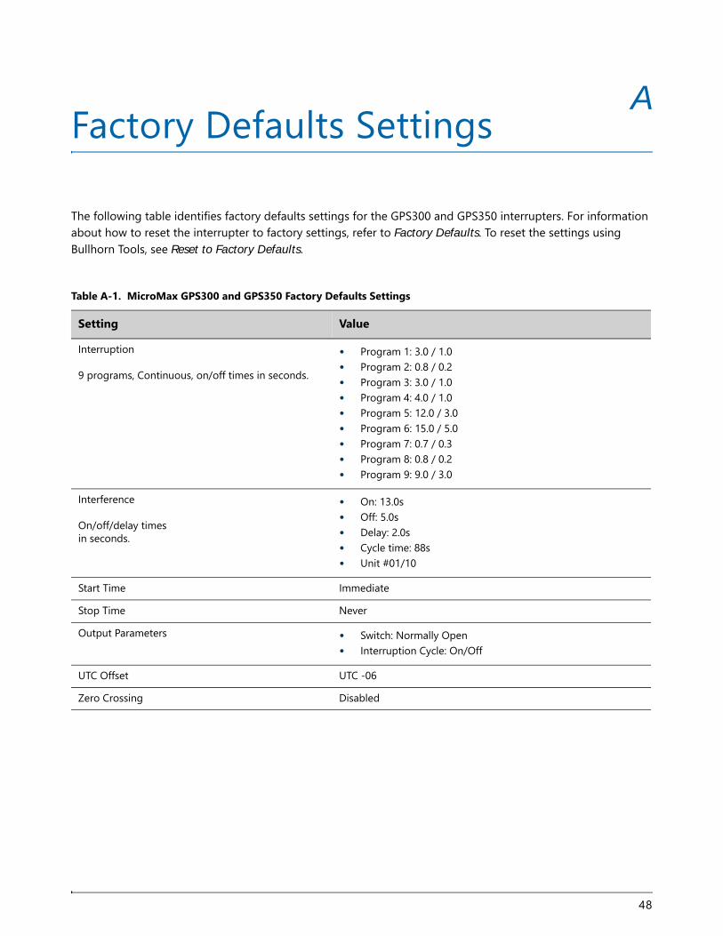
The following table identifies factory defaults settings for the GPS300 and GPS350 interrupters. For information about how to reset the interrupter to factory settings, refer to Factory Defaults. To reset the settings using Bullhorn Tools, see Reset to Factory Defaults.
Table A-1. MicroMax GPS300 and GPS350 Factory Defaults Settings
Setting Value
Interruption9 programs, Continuous, on/off times in seconds.
• Program 1: 3.0 / 1.0 • Program 2: 0.8 / 0.2 • Program 3: 3.0 / 1.0• Program 4: 4.0 / 1.0• Program 5: 12.0 / 3.0• Program 6: 15.0 / 5.0• Program 7: 0.7 / 0.3• Program 8: 0.8 / 0.2• Program 9: 9.0 / 3.0
InterferenceOn/off/delay times in seconds.
• On: 13.0s• Off: 5.0s• Delay: 2.0s• Cycle time: 88s• Unit #01/10
Start Time Immediate
Stop Time Never
Output Parameters • Switch: Normally Open• Interruption Cycle: On/Off
UTC Offset UTC -06
Zero Crossing Disabled
Mercury Relay Advisory B
The information in this section is intended to notify American Innovations (AI) customers of the manufacturer’s published limitations on mercury relays.
Customers primarily purchase mercury relays for use with current interrupters. Current interrupters provide great programming flexibility to enable customers to use a wide variety of interruption cycles.
AI supplies mercury relays from a variety of respected and reliable vendors including MDI and American Electronic Components (AEC). These manufacturers publish expected relay lives of 3 to 6 million cycles depending upon the type of relay selected. AEC, the manufacturer of Durakool relays, indicates that relay life will be significantly shortened at rates exceeding 1,500 cycles per hour. MDI recommends no more than 900 cycles per hour. Depending upon the interruption cycle chosen by the customer, it is possible to exceed the manufacturer’s recommendation, which would result in a likely reduction of service life.
As an example, customers who elect to use mercury relays to interrupt at 1 cycle per second will generate 3600 cycles per hour. Customers should consult the manufacturer’s documentation to select the appropriate relay for the application.
Durakool information can be found on the AEC web page at the following address:
http://www.aecsensors.com/html
In the Durakool documentation, the following two situations are explained that may impact the current carrying capacity of the relay: 1) cycle rate and 2) voltage values. The sizing tables indicate a methodology for determining the maximum amperage that can be carried depending upon the cycle rate. An additional derating table for mercury relays is provided for those instances where voltage in excess of 48 V DC is being interrupted. When selecting relays, customers should be aware of both of these derating tables to choose the best relay for the application.
To avoid depolarization of the CP system, the mercury relays we sell that AI sells are of the normally closed variety. It is possible that a normally closed relay will fail at the end of its life in the open position due to a malfunction of the spring mechanism which drives the plunger/contacts into a normally closed position. If this occurs, a depolarization situation would result. AI has the following two recommendations:
1 Customers using mercury relays should consider periodic replacement of these relays based upon engineering estimated life via a preventive maintenance program to reduce the likelihood of an open circuit failure.
2 If fast cycle operation is common, AI recommends a solid state relay for maximum life and reliability.
49
MicroMax Interrupters User Guide
Although most interrupters are capable of being programmed for faster interruption cycles, AI recommends that customers not exceed 900 cycles per hour (or a cycle time of less than four seconds) and will not warranty devices that are utilized in this manner. AI adds a serial number to relays that is supplied that we supply to enable the tracking of the shipment date. The approximate age of the relay may be used to assist AI in return material response, failure analysis, and warranty claims. Manufacturers will be consulted to help determine failure cause and to advise customers that warranties may not be honored if it is deemed that the mercury relay is used outside of recommended parameters.
If you have questions or need additional information, please contact Technical Support (800-229-3404). Office hours are Monday – Friday, 8:00 am – 5:00 pm, Central Time.
Mercury Relay Advisory 50
51
Regulatory Notices C
The following FCC requirements are met by the products described in this guide.
This equipment has been tested and found to comply with the limits for a Class B digital device, pursuant to part 15 of the FCC Rules. These limits are designed to provide reasonable protection against harmful interference in a residential installation. This equipment generates, uses, and can radiate radio frequency energy and, if not installed and used in accordance with the instructions, may cause harmful interference to radio communications. However, there is no guarantee that interference will not occur in a particular installation. If this equipment does cause harmful interference to radio or television reception, which can be determined by turning the equipment off and on, the user is encouraged to try to correct the interference by one or more of the following measures:
• Reorient or relocate the receiving antenna.
• Increase the separation between the equipment and receiver.
• Connect the equipment in an outlet on a circuit different from that to which the receiver is connected.
• Consult the dealer or an experienced radio/TV technician for help.
Export Control Classification NumberThe Export Control Classification Number (ECCN) assigned to the Bullhorn Tools software by the U.S. Bureau of Industry and Security (BIS) is as follows:
• ECCN Classification:No Classification
• ECCN Code:EAR99 or NLR