Micromachined Vibrating Gyroscopes Intro to MEMS final presentation December 12, 2002 presented by:...
23
Micromachined Vibrating Micromachined Vibrating Gyroscopes Gyroscopes Intro to MEMS final presentation Intro to MEMS final presentation December 12, 2002 December 12, 2002 presented by: presented by: Kimberly S. Elliot Kimberly S. Elliot Parag Gupta Parag Gupta Kyle Reed Kyle Reed Raquel C. Rodriguez Raquel C. Rodriguez
-
date post
21-Dec-2015 -
Category
Documents
-
view
217 -
download
0
Transcript of Micromachined Vibrating Gyroscopes Intro to MEMS final presentation December 12, 2002 presented by:...
Micromachined Vibrating Micromachined Vibrating GyroscopesGyroscopes
Intro to MEMS final presentationIntro to MEMS final presentationDecember 12, 2002December 12, 2002
presented by:presented by:
Kimberly S. ElliotKimberly S. Elliot
Parag GuptaParag Gupta
Kyle ReedKyle Reed
Raquel C. RodriguezRaquel C. Rodriguez

Presentation OutlinePresentation Outline
State-of-the-art reviewState-of-the-art review Introduction / ApplicationsIntroduction / Applications Operation PrinciplesOperation Principles
Two case studiesTwo case studies HARPSS Vibrating RingHARPSS Vibrating Ring Draper’s Tuning ForkDraper’s Tuning Fork
Conclusions and QuestionsConclusions and Questions
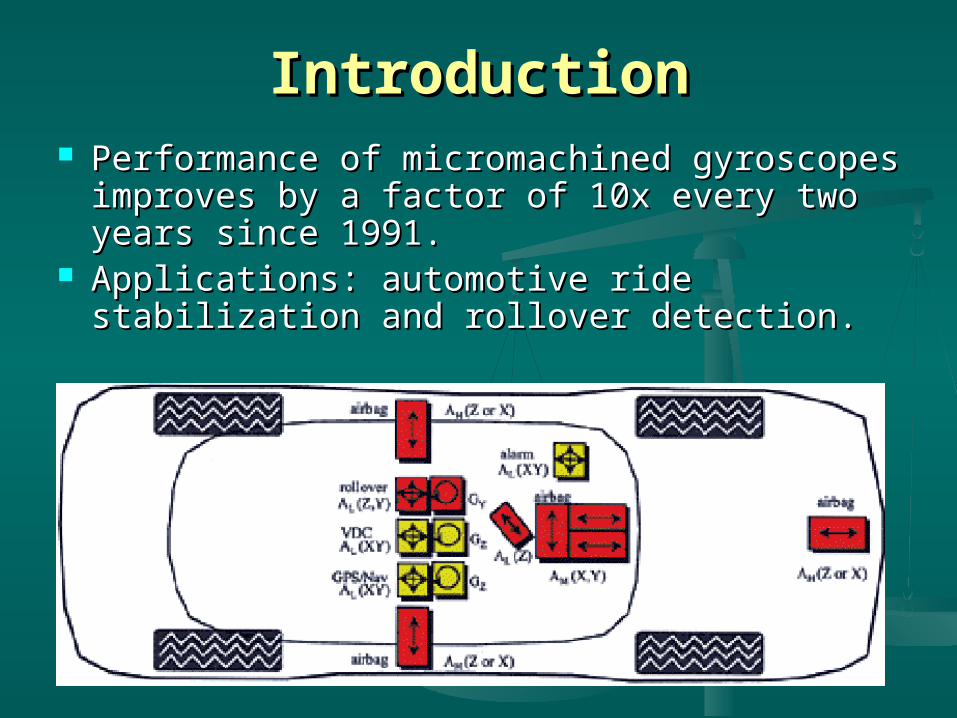
IntroductionIntroduction Performance of micromachined gyroscopes Performance of micromachined gyroscopes
improves by a factor of 10x every two years improves by a factor of 10x every two years since 1991.since 1991.
Applications: automotive ride stabilization and Applications: automotive ride stabilization and rollover detection.rollover detection.

Applications Applications (Cont’d)(Cont’d)
Guidance and Guidance and NavigationNavigation
Segway ScooterSegway Scooter Uses five MEMS Uses five MEMS
gyroscopes for tilt and gyroscopes for tilt and rotation detection.rotation detection.
Basic Operating PrinciplesBasic Operating Principles
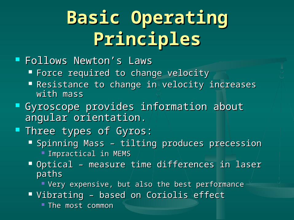
Follows Newton’s LawsFollows Newton’s Laws Force required to change velocityForce required to change velocity Resistance to change in velocity increases with massResistance to change in velocity increases with mass
Gyroscope provides information about angular Gyroscope provides information about angular orientation.orientation.
Three types of Gyros:Three types of Gyros: Spinning Mass – tilting produces precessionSpinning Mass – tilting produces precession
Impractical in MEMSImpractical in MEMS Optical – measure time differences in laser pathsOptical – measure time differences in laser paths
Very expensive, but also the best performanceVery expensive, but also the best performance Vibrating – based on Coriolis effectVibrating – based on Coriolis effect
The most commonThe most common

Basic ConfigurationBasic Configurationof Vibrating Gyroscopesof Vibrating Gyroscopes
Four main components:Four main components: Proof massProof mass Elastic springElastic spring DashpotDashpot Sensing methodSensing method
Proof mass is put into Proof mass is put into oscillation (x-axis)oscillation (x-axis)
Sensitive to angular Sensitive to angular rotation in the z-axisrotation in the z-axis
Induced Coriolis Induced Coriolis acceleration (y- axis)acceleration (y- axis)
Vibrating Gyroscope BasicsVibrating Gyroscope Basics
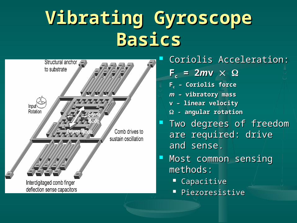
Coriolis Acceleration:Coriolis Acceleration:
FFcc = 2 = 2mmv v FFcc – Coriolis force – Coriolis force
mm – vibratory mass – vibratory mass
v – linear velocityv – linear velocity
- angular rotation- angular rotation
Two degrees of freedom Two degrees of freedom are required: drive and are required: drive and sense.sense.
Most common sensing Most common sensing methods:methods: CapacitiveCapacitive PiezoresistivePiezoresistive
Performance conceptsPerformance concepts
Scale factor: amount of change in output Scale factor: amount of change in output per unit change rotation [V/(per unit change rotation [V/(/s)]/s)]
• Zero-rate output (ZRO): output in the Zero-rate output (ZRO): output in the absence of angular rate, it’s the sum of absence of angular rate, it’s the sum of white noise and a slowly varying functionwhite noise and a slowly varying function• Noise defines resolution [(Noise defines resolution [(/s)//s)/Hz]Hz]• Slowly varying function defines drift [Slowly varying function defines drift [/s]/s]

HARPSS Vibrating Ring GyroscopeHARPSS Vibrating Ring Gyroscope
HHigh igh AAspect-spect-RRatio Combined atio Combined PPoly and oly and SSingle-Crystal ingle-Crystal SSilicon.ilicon. Developed at The University of Michigan.Developed at The University of Michigan. Vibrating ring and eight support springs.Vibrating ring and eight support springs. Each spring with two electrodes for drive and sensing, and to Each spring with two electrodes for drive and sensing, and to
compensate asymmetries.compensate asymmetries. Capacitive sensing.Capacitive sensing.
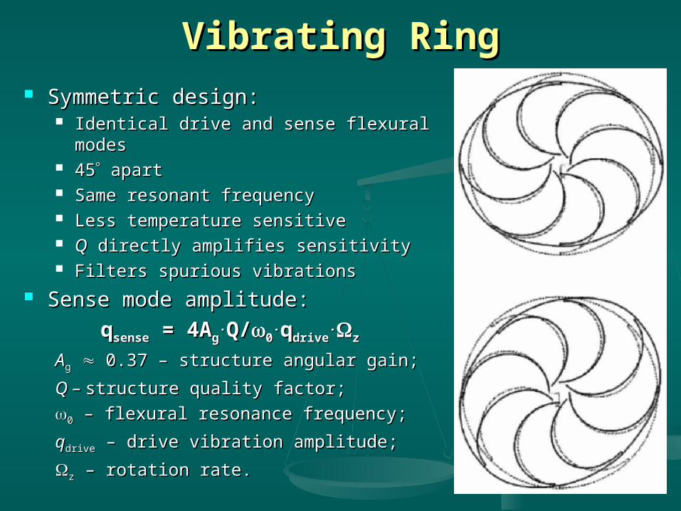
Vibrating RingVibrating Ring Symmetric design:Symmetric design:
Identical drive and sense flexural modesIdentical drive and sense flexural modes 4545 apart apart Same resonant frequencySame resonant frequency Less temperature sensitiveLess temperature sensitive QQ directly amplifies sensitivity directly amplifies sensitivity Filters spurious vibrationsFilters spurious vibrations
Sense mode amplitude:Sense mode amplitude:
qqsensesense = 4A = 4Agg..Q/Q/00
..qqdrivedrive..zz
AAgg 0.37 – structure angular gain; 0.37 – structure angular gain;
Q – Q – structure quality factor;structure quality factor;
00 – flexural resonance frequency; – flexural resonance frequency;
qqdrivedrive – drive vibration amplitude; – drive vibration amplitude;
zz – rotation rate. – rotation rate.
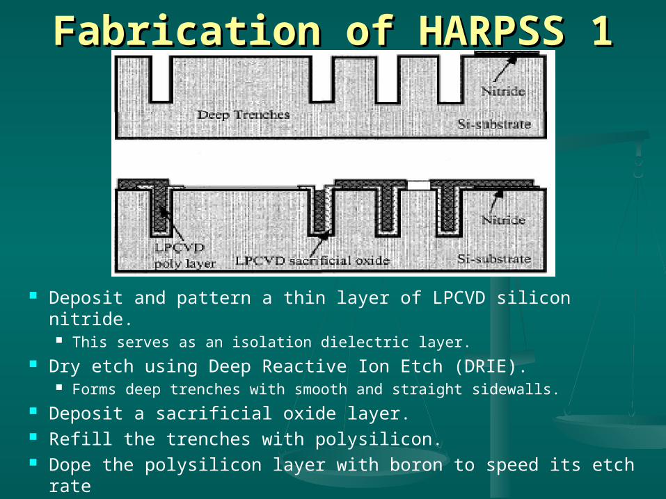
Fabrication of HARPSS 1Fabrication of HARPSS 1
Deposit and pattern a thin layer of LPCVD silicon nitride. This serves as an isolation dielectric layer.
Dry etch using Deep Reactive Ion Etch (DRIE). Forms deep trenches with smooth and straight sidewalls.
Deposit a sacrificial oxide layer. Refill the trenches with polysilicon. Dope the polysilicon layer with boron to speed its etch rate

Fabrication of HARPSS 2Fabrication of HARPSS 2
Deposit and pattern Cr/Au. Dry directional/isotropic SF6 silicon etch to release silicon sense
electrodes. Involves a deep, directional etch followed by an isotropic SF6 silicon
etch. Using HF:H2O, etch away the sacrificial oxide
Creates capacitive air gaps between the sense-electrodes and the ring structure.
HARPSS GyroscopeHARPSS Gyroscope
Advantages:Advantages: Small ring-to-electrode gapSmall ring-to-electrode gap Large structural heightLarge structural height Better structural materialBetter structural material
Sensitivity Sensitivity 200 [ 200 [V/(V/(/s)]/s)]• For Q For Q 1200, resolution 1200, resolution 0.01 [ 0.01 [/s] for 1 /s] for 1
Hz bandwidthHz bandwidth Min.detectable signal Min.detectable signal 5x10 5x10⁻³-3 [ [/s] for 10 /s] for 10
Hz bandwidthHz bandwidth
HARPSS LimitationsHARPSS Limitations
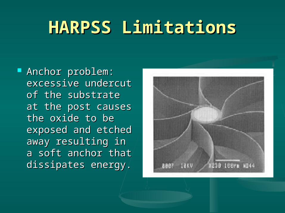
Anchor problem: Anchor problem: excessive undercut of excessive undercut of the substrate at the the substrate at the post causes the oxide post causes the oxide to be exposed and to be exposed and etched away resulting etched away resulting in a soft anchor that in a soft anchor that dissipates energy.dissipates energy.
HARPSS Limitations 2HARPSS Limitations 2
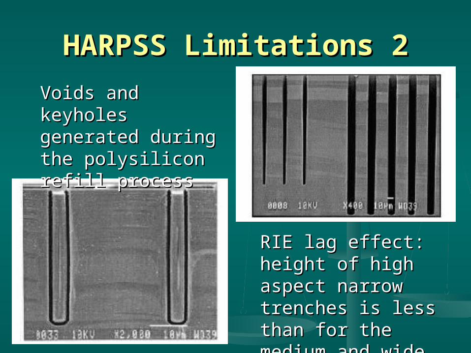
Voids and keyholes Voids and keyholes generated during the generated during the polysilicon refill polysilicon refill processprocess
RIE lag effect: height RIE lag effect: height of high aspect narrow of high aspect narrow trenches is less than trenches is less than for the medium and for the medium and wide ones.wide ones.

Basic Tuning Fork GyroscopeBasic Tuning Fork Gyroscope
Tines resonated to fixed amplitude.Tines resonated to fixed amplitude. When rotated,When rotated, Coriolis force Coriolis force
causes a sinusoidal force on tines.causes a sinusoidal force on tines. This force detected as a bending of This force detected as a bending of
the tines or as a torsional vibration the tines or as a torsional vibration
of junction bar.of junction bar. Capacitive, piezoresistive, or Capacitive, piezoresistive, or
piezoelectric detection mechanisms.piezoelectric detection mechanisms.
i
Draper’s Tuning ForkDraper’s Tuning Fork
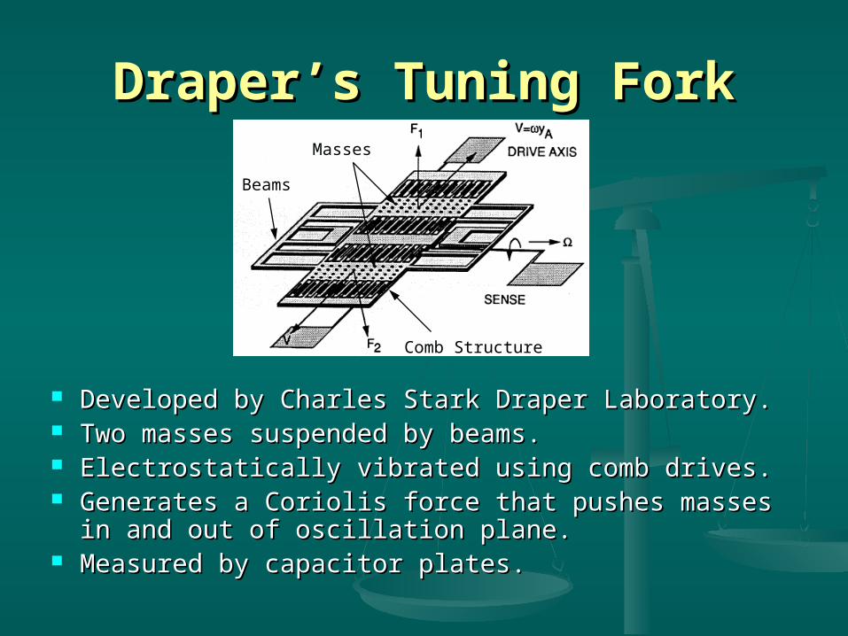
Developed by Charles Stark Draper Laboratory.Developed by Charles Stark Draper Laboratory. Two masses suspended by beams.Two masses suspended by beams. Electrostatically vibrated using comb drives.Electrostatically vibrated using comb drives. Generates a Coriolis force that pushes masses in and out of Generates a Coriolis force that pushes masses in and out of
oscillation plane.oscillation plane. Measured by capacitor plates.Measured by capacitor plates.
Comb Structure
Beams
Masses
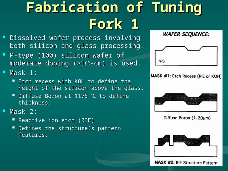
Fabrication of Tuning Fork 1Fabrication of Tuning Fork 1 Dissolved wafer process involving both Dissolved wafer process involving both
silicon and glass processing.silicon and glass processing. P-type (100) silicon wafer of moderate P-type (100) silicon wafer of moderate
doping (>1doping (>1-cm) is used.-cm) is used. Mask 1: Mask 1:
Etch recess with KOH to define the height Etch recess with KOH to define the height of the silicon above the glass.of the silicon above the glass.
Diffuse Boron at 1175 Diffuse Boron at 1175 C to define C to define thickness.thickness.
Mask 2:Mask 2: Reactive ion etch (RIE). Reactive ion etch (RIE). Defines the structure’s pattern features.Defines the structure’s pattern features.

Fabrication of Tuning Fork 2Fabrication of Tuning Fork 2
Glass wafer processed separately.Glass wafer processed separately. Mask 3:Mask 3:
Recess glass 1600 Angstroms.Recess glass 1600 Angstroms. Deposit and lift off a multi-metal Deposit and lift off a multi-metal
system.system. Result: Metal protrudes 500 Result: Metal protrudes 500
Angstroms above the glass.Angstroms above the glass.
The metal forms the sense and The metal forms the sense and drive plates of the capacitor and drive plates of the capacitor and the output leads from the the output leads from the transducer.transducer.
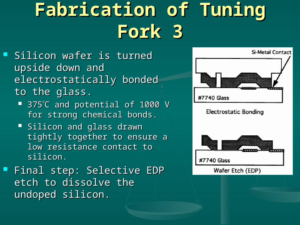
Fabrication of Tuning Fork 3Fabrication of Tuning Fork 3
Silicon wafer is turned upside down Silicon wafer is turned upside down and electrostatically bonded to the and electrostatically bonded to the glass.glass. 375375C and potential of 1000 V for C and potential of 1000 V for
strong chemical bonds.strong chemical bonds. Silicon and glass drawn tightly together Silicon and glass drawn tightly together
to ensure a low resistance contact to to ensure a low resistance contact to silicon.silicon.
Final step: Selective EDP etch to Final step: Selective EDP etch to dissolve the undoped silicon.dissolve the undoped silicon.
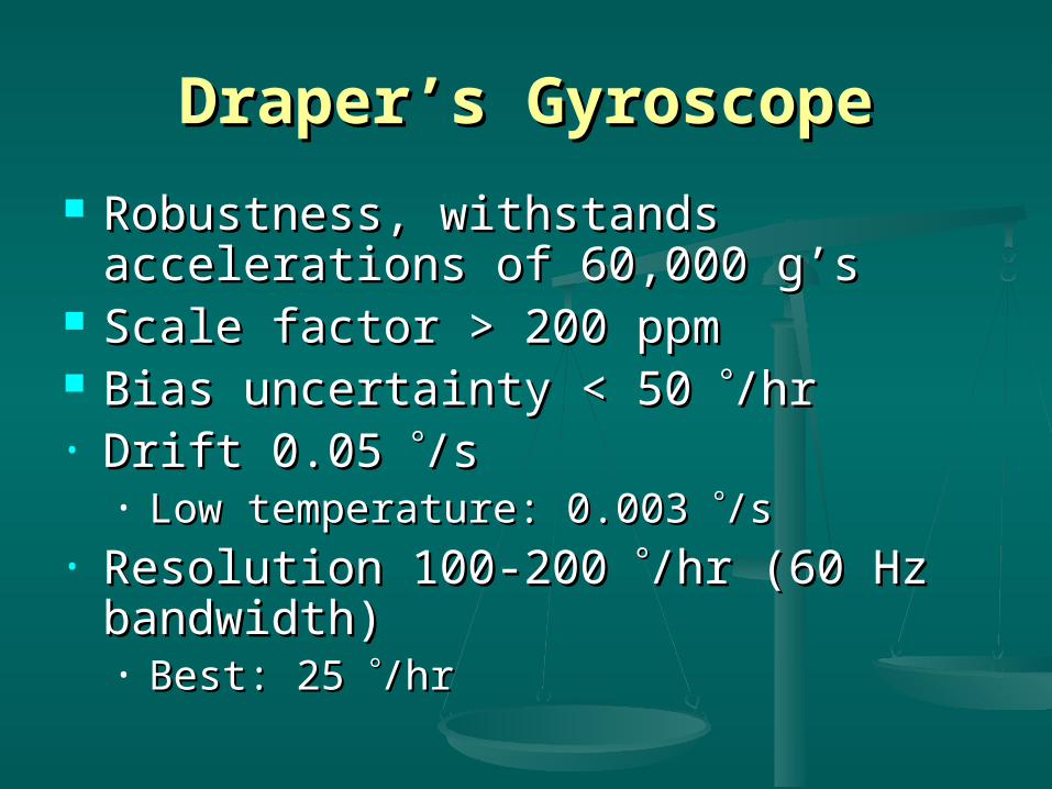
Draper’s GyroscopeDraper’s Gyroscope
Robustness, withstands accelerations of Robustness, withstands accelerations of 60,000 g’s60,000 g’s
Scale factor > 200 ppmScale factor > 200 ppm Bias uncertainty < 50 Bias uncertainty < 50 /hr/hr• Drift 0.05 Drift 0.05 /s/s
• Low temperature: 0.003 Low temperature: 0.003 /s/s• Resolution 100-200 Resolution 100-200 /hr (60 Hz bandwidth)/hr (60 Hz bandwidth)
• Best: 25 Best: 25 /hr/hr

ConclusionsConclusions
Early development phase for Early development phase for micromachined gyroscopes.micromachined gyroscopes.
HARPSS yields a gyroscope with excellent HARPSS yields a gyroscope with excellent mode matching, high resolution, low ZRO mode matching, high resolution, low ZRO and long-term stability.and long-term stability.
Draper Lab produces a low-cost Draper Lab produces a low-cost gyroscope of small size and considerable gyroscope of small size and considerable ruggedness.ruggedness.

Any Questions?Any Questions?