MICROLINE® 520/521 Printer Handbook
47
Chapter 0 Manual Front Cover MICROLINE ® 520/521 Printer Handbook 59256804 Printed in USA Division of Oki America, Inc. ML520/521 ( 96-02-04 )
-
Upload
wembleystadiumevents -
Category
Documents
-
view
229 -
download
0
Transcript of MICROLINE® 520/521 Printer Handbook

8/8/2019 MICROLINE® 520/521 Printer Handbook
http://slidepdf.com/reader/full/microline-520521-printer-handbook 1/47
Chapter 0
Manual Front Cover
MICROLINE ® 520/521 Printer Handbook
59256804Printed in USADivision of Oki America, Inc.
ML520/521 ( 96-02-04 )
8/8/2019 MICROLINE® 520/521 Printer Handbook
http://slidepdf.com/reader/full/microline-520521-printer-handbook 2/47
Chapter 1
Unpacking
Unpacking
Choose a sturdy table, desk or printer stand to place your printer on when you remove it from the carton.Be sure to save all packing materials in case you need to ship the printer again. Check the box for thesecontents:
1) Printer2) Ribbon cartridge3) Power cord
Note: Interface cable and paper are sold separately.If any of these items is missing or damaged, seeyour dealer immediately for a replacement.
ML520/521 ( 96-02-04 )

8/8/2019 MICROLINE® 520/521 Printer Handbook
http://slidepdf.com/reader/full/microline-520521-printer-handbook 3/47
Remove The Protective Film
Remove The Protective Film
Peel the clear protective film from the carriage cover (1). Lift up on the ridged area at either end of thecarriage cover ( 2 ), and peel the clear protective film from the access cover ( 3 ). Press the carriagecover back into place.
ML520/521 ( 96-02-04 )

8/8/2019 MICROLINE® 520/521 Printer Handbook
http://slidepdf.com/reader/full/microline-520521-printer-handbook 4/47
Remove The Shipping Retainers
Remove The Shipping Retainers
Open the access cover ( 1 ) by grasping the tabs at either end and lifting. Remove the printhead shippingretainer ( 2 ), leaving the cover open. Grasp the front edge of the paper separator ( 3 ) and pull it up.Remove the styrofoam shipping retainer, then lower the paper separator and press it into place.
ML520/521 ( 96-02-04 )

8/8/2019 MICROLINE® 520/521 Printer Handbook
http://slidepdf.com/reader/full/microline-520521-printer-handbook 5/47
Install (or Replace) The Ribbon Cartridge
Install (or Replace) The Ribbon Cartridge
Note: Be sure to use only ribbons specifically for use with MICROLINE 520/521 printers. For best results,use genuine OKIDATA ribbons, Part No. 52107001.
With the access cover open, slide the printhead ( 1 ) to the center of the platen.
Caution!!! Printhead may be hot!!!
If you're replacing the ribbon, lift up the cartridge at the end nearest the platen, then lift it out, and discardit.
Remove the new ribbon cartridge from its packaging.
Holding the ribbon cartridge with the knob ( 2 ) facing up and the ribbon shield ( 3 ) facing the platen, fitthe grooves on either side at the back end of the cartridge over the pins on the ribbon plate ( 4 ). Lower
the front of the the cartridge over the printhead ( 5 ) until it snaps into place, then turn the knob ( 2 ) in thedirection of the arrow (clockwise) to take up the ribbon slack.
ML520/521 ( 96-02-04 )
8/8/2019 MICROLINE® 520/521 Printer Handbook
http://slidepdf.com/reader/full/microline-520521-printer-handbook 6/47
ML520/521 ( 96-02-04 )
8/8/2019 MICROLINE® 520/521 Printer Handbook
http://slidepdf.com/reader/full/microline-520521-printer-handbook 7/47
Connect to Power and Computer
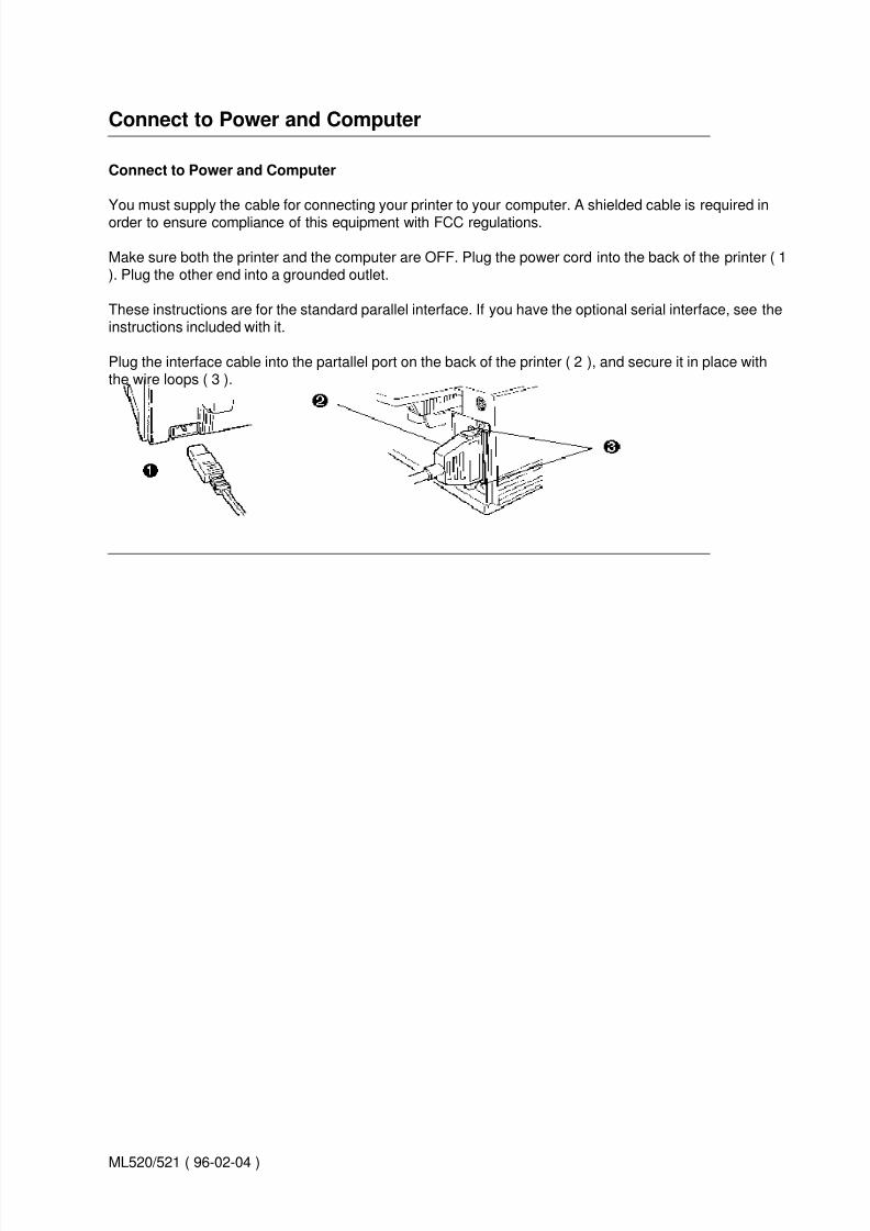
Connect to Power and Computer
You must supply the cable for connecting your printer to your computer. A shielded cable is required inorder to ensure compliance of this equipment with FCC regulations.
Make sure both the printer and the computer are OFF. Plug the power cord into the back of the printer ( 1). Plug the other end into a grounded outlet.
These instructions are for the standard parallel interface. If you have the optional serial interface, see theinstructions included with it.
Plug the interface cable into the partallel port on the back of the printer ( 2 ), and secure it in place withthe wire loops ( 3 ).
ML520/521 ( 96-02-04 )

8/8/2019 MICROLINE® 520/521 Printer Handbook
http://slidepdf.com/reader/full/microline-520521-printer-handbook 8/47
Power Up
Power Up
Turn the printer on. The printhead will cross back and forth along the platen, and the pins will gently fireto determine the printhead gap setting. The POWER light will come on. The ALARM light will also comeon, but don't be concerned: it's just telling you that there is no paper loaded.
ML520/521 ( 96-02-04 )

8/8/2019 MICROLINE® 520/521 Printer Handbook
http://slidepdf.com/reader/full/microline-520521-printer-handbook 9/47
Chapter 2
Loading paper
Your printer has provision for· Single sheets (top feed)· Continuous-forms (rear feed)
You can also install options:· Cut Sheet Feeder, for top feed, holds 100 sheets· Push and/ or Pull Tractors, for bottom feed of continuous forms, including
- labels- heavy card stock- multi-part forms
Note: See the instructions provided with the options for information on installing them andloading paperwith the option installed.
Your printers innovative, smart printhead automatically detects and adjusts to the thickness of the paperyou're using, so you don't have to fuss with setting the printhead gap when you change the type of paperor print path youre using.
See Appendix A for more details on the types and sizes of print media you can use.( )
ML520/521 ( 96-02-04 )

8/8/2019 MICROLINE® 520/521 Printer Handbook
http://slidepdf.com/reader/full/microline-520521-printer-handbook 10/47
Loading Rear- Feed Paper
Loading Rear- Feed Paper
The rear-feed path is recommended for printing reports, etc., on single-thickness,continuous-form paper. For graphics or charts, it's best to use the single-sheet paper path.
Note: If you have any paper in the paper path, be sure to remove it from the path beforeinstalling rear-feed paper!
Move the paper lever to the position marked REAR ( 1 ). Grasp the front edge of the paperseparator ( 2 ) and pull it up to access the tractors ( 3 ).
Pull up on the tractor lock levers ( 4 ) to release them, then open the tractor covers ( 5 ). Positionthe right- hand tractor for the width of the paper you're loading. Pull the paper through theopening between the printer and the rear cover, and place the first two holes on each side overthe tractor pins ( 6 ). Please note that an equal number of paper holes must be engaged on eithertractor in order to ensure proper paper feed.
Note: The movement of the left tractor is limited to ensure that the paper will always contactthe paper sensor when loaded.
Close the tractor covers and adjust the left tractor to position the edge of the paper: reference
ML520/521 ( 96-02-04 )

8/8/2019 MICROLINE® 520/521 Printer Handbook
http://slidepdf.com/reader/full/microline-520521-printer-handbook 11/47
marks ( 7 ) on the printer indicate the left edge position for the two most common paper sizes.Lock the left tractor in place by pushing back on the lock lever. Adjust the right tractor so that thepaper holes are centered on the pins (careful if paper is stretched too tight or left too loose, it can jam and cause problems), then lock the right tractor in place by pushing back on the lock lever.
Close the paper separator ( 8 ) and flip the wire feed guide ( 9 ) over onto the pull-up rollerassembly.
Note: The wire feed guide keeps paper from curling back into the printer.
Push the FF/ LOAD button. The paper automatically feeds into the printer and the ALARM lightgoes out. The printhead moves back and forth, gently firing the pins to sense the paper thicknessand set the printhead gap.Check the baseline for the Top of Form (TOF), indicated by the red lineon the clear plastic paper shield ( 10 ). If its OK, press the SEL button and you're ready to startprinting. If it needs adjustment, set the Top of Form following the instructions on page 16( )
ML520/521 ( 96-02-04 )

8/8/2019 MICROLINE® 520/521 Printer Handbook
http://slidepdf.com/reader/full/microline-520521-printer-handbook 12/47
Loading Single-Sheet Paper
Loading Single-Sheet Paper
The single sheet path is best for letterhead stationery, memos, and envelopes and is recommended forprinting graphs and charts because it provides the most accurate control of the paper.
Note: If you have any continuous-form paper in the paper path, you must press the PARK button on thefront panel to remove it from the path before loading single sheets.
Make sure the printer is turned ON and deselected (SEL light off press SEL button to deselect ifnecessary).
Note: The ALARM light will remain on until paper is loaded.Move the paper lever to the position markedTOP (1 )
Grasp the back of the paper separator and unsnap it from the housing, then swing it up into the single-sheet feed position ( 2 ), making sure that the wire feed guide is nestled in the separator. Adjust thepaper feed guides for the width of the paper and drop a sheet of paper into the separator ( 3 ). The paperwill automatically feed into the printer, and the printhead will move back and forth, gently firing the pins tosense the paper thickness and set the printhead gap.
Note: If the paper doesn't feed in properly, the "15" light on the control panel will begin flashing. Tocorrect this, press theSHIFT and RESET buttons simultaneously, then reload the sheet.
Check the baseline for the Top of Form (TOF), indicated by the red line on the clear plastic paper shield (Í ). If its OK, press the SEL button and youre ready to start printing. If it needs adjustment, set the Top ofForm following the instructions on the next page.
ML520/521 ( 96-02-04 )

8/8/2019 MICROLINE® 520/521 Printer Handbook
http://slidepdf.com/reader/full/microline-520521-printer-handbook 13/47
ML520/521 ( 96-02-04 )

8/8/2019 MICROLINE® 520/521 Printer Handbook
http://slidepdf.com/reader/full/microline-520521-printer-handbook 14/47
Setting Top of Form
Setting Top of Form
Make sure the printer is deselected (SEL light off if necessary, press SEL button to deselect printer).
Hold down the SHIFT button ( 1 ) and press:
FF/ LOAD button ( 2 ) to move the paper up in micro increments (TOF lower on page), orLF button ( 3 ) to move the paper down in micro increments (TOF higher on page).
The red line ( 4 ) on the clear plastic paper shield shows the baseline of the current printing position tohelp you place the top of form.
When you're done setting the TOF, press the SEL button ( 5 ) to reselect the printer.
ML520/521 ( 96-02-04 )

8/8/2019 MICROLINE® 520/521 Printer Handbook
http://slidepdf.com/reader/full/microline-520521-printer-handbook 15/47
Temporarily Changing Top of Form Setting
Temporarily Changing Top of Form Setting
To temporarily change the Top of Form setting for a particular print job, deselect the printer (press SELbutton) and press the LF button (1 ) until you reach the TOF position you want to use. The printer willretain this setting until you turn it off.
ML520/521 ( 96-02-04 )

8/8/2019 MICROLINE® 520/521 Printer Handbook
http://slidepdf.com/reader/full/microline-520521-printer-handbook 16/47
Resetting Top of Form to Default
Resetting Top of Form to Default
To reset the Top of Form to the factory default, turn off printer, then hold down the QUIET ( 2 ) andPARK ( 3 ) buttons while turning printer back on.
ML520/521 ( 96-02-04 )

8/8/2019 MICROLINE® 520/521 Printer Handbook
http://slidepdf.com/reader/full/microline-520521-printer-handbook 17/47
Tear Feature
Tear Feature
When you're using continuous forms with either the built-in rear-feed tractor or the optional bottom- feedpush tractor, you can use this feature to advance the forms up to the tear position so you can easily tearoff a printed sheet without wasting paper or readjusting the printer. To do this, press the TEAR button ( 1) on the front panel.
Note: The tear feature can not be used when the optional pull tractor is installed.
ML520/521 ( 96-02-04 )

8/8/2019 MICROLINE® 520/521 Printer Handbook
http://slidepdf.com/reader/full/microline-520521-printer-handbook 18/47
Forms Tear- off Feature
Forms Tear-off Feature
Note: Never Engage the Forms Tear-off when printing on labels!
The Forms Tear-off feature can be engaged to automatically move the paper up to the tear position afterthe selected interval (500 milliseconds, 1 second, or 2 seconds). The page will stay in the tear-off positionuntil the printer receives data. It will then move down to the initial printing position.
This feature is normally turned off. To activate it:
1. Hold the SHIFT button ( 1 ) and press the SEL button ( 2 ) to enter the Menu mode.
2. Press the GROUP button ( 3 ) until the line Rear Feed Form Tear- Off Off prints.
3. Press the SET button ( 4 ) until the time interval you wish to select prints .
4. Hold the SHIFT button ( 1 ) and press the SEL button ( 2 ) to exit the Menu mode andsave the setting.
Some programs pause occasionally while sending data. If the pause lasts more than the selectedinterval, the paperwill advance to the tear-off position until more data is received. This extra papermovement can cause uneven printregistration in graphics. If you have this problem, use the menu todeactivate Forms Tear-Off.
If you have problems setting the Top of Form high enough on the page when using Forms Tear-Off, seeProblem Solving in Chapter 6.( )
ML520/521 ( 96-02-04 )

8/8/2019 MICROLINE® 520/521 Printer Handbook
http://slidepdf.com/reader/full/microline-520521-printer-handbook 19/47
Paper Park Feature
Paper Park Feature
To switch from continuous form paper to another paper path, tear off the printed pages, then press thePARK button ( 1 ). The continuous-form paper immediately retracts from the paper path.
ML520/521 ( 96-02-04 )
8/8/2019 MICROLINE® 520/521 Printer Handbook
http://slidepdf.com/reader/full/microline-520521-printer-handbook 20/47

8/8/2019 MICROLINE® 520/521 Printer Handbook
http://slidepdf.com/reader/full/microline-520521-printer-handbook 21/47
Clearing Paper Jams - Rear Feed Jams
Clearing Paper Jams
Note: Always turn the printer off before you turn the platen knob!
Clearing Rear Feed JamsTo clear a rear- feed paper jam, turn off printer then turn the platen knob to back the paper out of theprinter. Remove any ripped pieces of paper. Reload the paper, turn the printer back on and press the FF/ LOAD button.
Correcting for Continuing Rear-Feed JamsIf the paper keeps jamming, you probably have bits of paper stuck in the paper path. Turn off the printer.Use the platen knob to back the paper out. Open the access cover and lift off the pull- up roller assembly( 1 ). Lift the paper separator, open the tractors and remove the paper ( 2 ). Fold some continuous- feedpaper over three times to make a page four sheets thick and load it on the tractors ( 3 ). Use the platenknob to draw the sheet around the platen: this brings any jammed bits of paper out. Back the sheet out,
replace the roller assembly, and reload regular paper. Close the access cover, turn the printer on, andpress FF/ LOAD.
ML520/521 ( 96-02-04 )

8/8/2019 MICROLINE® 520/521 Printer Handbook
http://slidepdf.com/reader/full/microline-520521-printer-handbook 22/47
Clearing Single Sheet Feed Jams
Clearing Single Sheet Feed Jams
Turn the printer off, then rotate the platen knob to back the jammed paper out of the carriage. Ifnecessary, open the access cover and lift off the pull-up roller assembly ( 1 ) to provide access to removeany ripped pieces from around the carriage.
Check the baseline for the Top of Form (TOF), indicated by the red line on the clear plastic paper shield (4 ). If its OK, press the SEL button
ML520/521 ( 96-02-04 )

8/8/2019 MICROLINE® 520/521 Printer Handbook
http://slidepdf.com/reader/full/microline-520521-printer-handbook 23/47
Chapter 3
Testing Your Printer: Rolling ASCII & Font Sample
Tests
After you've installed ribbon and paper, you're ready to run the self tests. Do this any time you want tomake sure the printer is functioning properly.
Font Sample TestHold down the LF button while turning on the printer to produce a limited sample of the available printstyles. When the test is complete (one page), the printer stops and the SEL light goes on.Note: To stop the test before its done, press the SEL button.
Rolling ASCII TestHold down the QUIET button while turning on the printer to produce a continuous sample of the default
print style. To stop the test, press the SEL button.
Note: For wide carriage Model 521, be sure you have wide paper loaded!
ML520/521 ( 96-02-04 )

8/8/2019 MICROLINE® 520/521 Printer Handbook
http://slidepdf.com/reader/full/microline-520521-printer-handbook 24/47
Chapter 4
Basic Terminology Printer Commands
Basic Terminology Printer Commands
Printer commands are signals sent by your computer to the printer which guide and control the operation.They usually begin with the ESC character and can be sent in decimal, ASCII, or hexadecimal form.
Note: If youre using commercial software with an appropriate printer driver selected (see next page),printer commandswill normally be sent to your printer by the software and you wont even need to thinkabout them.
ML520/521 ( 96-02-04 )

8/8/2019 MICROLINE® 520/521 Printer Handbook
http://slidepdf.com/reader/full/microline-520521-printer-handbook 25/47
Emulations
Emulations
Your printer has three emulations:
· IBM Proprinter III (factory default)· Epson FX· OKIDATA Microline Standard
ML520/521 ( 96-02-04 )
8/8/2019 MICROLINE® 520/521 Printer Handbook
http://slidepdf.com/reader/full/microline-520521-printer-handbook 26/47
Changing Emulations
Changing Emulations
Your printer is set at the factory for the IBM Proprinter III emulation. To change the emulation, enter theMenu mode by holding the SHIFT button while pressing the SEL button. The following line will print:
Printer Control Emulation Mode IBM PPR
Press the SET button until the emulation you wish to select prints. Then exit the Menu and save yoursetting by once again holding the SHIFT button while pressing the SEL button.
ML520/521 ( 96-02-04 )

8/8/2019 MICROLINE® 520/521 Printer Handbook
http://slidepdf.com/reader/full/microline-520521-printer-handbook 27/47
Printer Drivers
Printer Drivers
Commercial software packages use printer drivers to control the appearance of printed documents. Aprinter driver is a set of printer commands which cause the printer to perform various functions at therequest of the software. When you use your printer with a software package, you must use the softwareto select a printer driver which is compatible with your printer (see next page)( ).
ML520/521 ( 96-02-04 )

8/8/2019 MICROLINE® 520/521 Printer Handbook
http://slidepdf.com/reader/full/microline-520521-printer-handbook 28/47
Selecting a Printer Driver
Selecting a Printer Driver
The drivers in the table below are listed by decreasing compatibility with your printer: use one as close tothe top of the list as possible. If your software does not have a printer driver from near the top of the list,call them to see if they have added any drivers to those supplied when you purchased your software.
Note: Check your software documentation for instructions on how to install a printer driver.
Printer Drivers
IBM Proprinter III EmulationOkidata ML 520/ 1 IBMIBM Proprinter IIIIBM Proprinter II
IBM ProprinterIBM Graphics Printer
Epson FX EmulationOkidata ML 520/ 1 EpsonEpson FX850/ 1050Epson FX86/ 286Epson FX Epson EX800/ 1000
OKIDATA Microline Standard EmulationOkidata Microline 520/ 521Okidata Microline 320/ 321
Okidata Microline 292/ 293Okidata Microline 192/ 193Okidata Microline 182/ 183Okidata Microline 92/ 93Okidata Microline 82A/ 83A
Note: OKIDATA drivers are available for Microsoft®WindowsTM 3.1, Microsoft Word 5.0/5.5/6.0, and forWordPerfect®5.1/5.2/6.0: call the OKILINK®II BBS at (609) 234-5344 and download them, or mail yourrequest for a driver diskette(# MS-8838 for 3½ or # MS-8839 for 5¼) to OKIDATA, P.O. Box 4603,Trenton, NJ 08650-9852.
ML520/521 ( 96-02-04 )

8/8/2019 MICROLINE® 520/521 Printer Handbook
http://slidepdf.com/reader/full/microline-520521-printer-handbook 29/47
Chapter 5
Control Panel Indicator Lights
Control Panel Indicator Lights
ML520/521 ( 96-02-04 )
8/8/2019 MICROLINE® 520/521 Printer Handbook
http://slidepdf.com/reader/full/microline-520521-printer-handbook 30/47
Control Panel Buttons: Print Mode
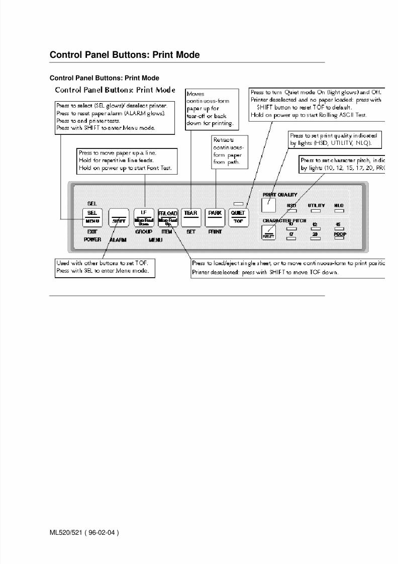
Control Panel Buttons: Print Mode
ML520/521 ( 96-02-04 )
8/8/2019 MICROLINE® 520/521 Printer Handbook
http://slidepdf.com/reader/full/microline-520521-printer-handbook 31/47
Control Panel Buttons: Menu Mode
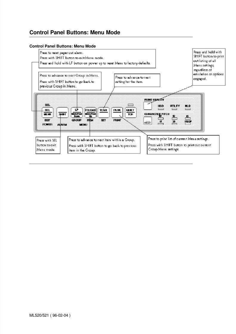
Control Panel Buttons: Menu Mode
ML520/521 ( 96-02-04 )

8/8/2019 MICROLINE® 520/521 Printer Handbook
http://slidepdf.com/reader/full/microline-520521-printer-handbook 32/47
Print Mode
Print Mode
The seven buttons to the left on your control panel are multi-function buttons. In the print mode, they areused to manipulate the paper (see the illustration on the first page of this chapter).The PRINT QUALITYand CHARACTER PITCH buttons on the right side of the control panel are used to select the quality andsize of the printing.
Note: The print quality and character pitch set by means of the front panel can be overridden bycommands sent by thecommercial software package from which you're printing a document. If you runinto this problem, see Problem Solving in Chapter 6 for information on how to correct it.()
ML520/521 ( 96-02-04 )

8/8/2019 MICROLINE® 520/521 Printer Handbook
http://slidepdf.com/reader/full/microline-520521-printer-handbook 33/47
Selecting Print Quality
Selecting Print Quality
Press the PRINT QUALITY button successively until the light underneath the print quality you wish toengage is lit:
Note: Your printer also prints bar codes accessible through printer commands. For more information onprogramming barcodes, mail your request for # MS- 8837 OKIDATA MICROLINE Reference Manual toOKIDATA, P.O. Box 4603,Trenton, NJ 08650-9852.
ML520/521 ( 96-02-04 )

8/8/2019 MICROLINE® 520/521 Printer Handbook
http://slidepdf.com/reader/full/microline-520521-printer-handbook 34/47
Selecting Character Pitch
Selecting Character Pitch
Note: If the SI command is received from your software, the character pitch selected on the control panelwill be overridden by the SI command.
Character pitch determines the width of the individual characters and is measured in characters per inch(cpi).
Press the CHARACTER PITCH button successively to page through the possible selections.
Epson and IBM emulations 10 cpi, 12 cpi, 15 cpi, 17 cpi, 20 cpi, or Proportional. The lights indicatewhich pitch is selected.
OKIDATA Microline Standard emulation 10, 12, 15, 17, or 20 cpi, either non-proportional orproportional: proportional is selected when both the light under the desired cpi and the light underPROP are lit.
To reset the character pitch to the factory default (10 cpi), make sure the printer is deselected (SEL lightout), then hold the SHIFT button while pressing CHARACTER PITCH button.
ML520/521 ( 96-02-04 )

8/8/2019 MICROLINE® 520/521 Printer Handbook
http://slidepdf.com/reader/full/microline-520521-printer-handbook 35/47
Available Fonts
Available Fonts
Typeface Spacing
NLQ Courier 10 cpi*, 12 cpi, 15 cpi, 17 cpi, 20 cpi, Proportional
NLQ Letter Gothic 10 cpi*, 12 cpi, 15 cpi, 17 cpi, 20 cpi, Proportional
Utility (Gothic) 10 cpi*, 12 cpi, 15 cpi, 17 cpi, 20 cpi, Proportional
High Speed Draft(Gothic) 10 cpi*, 12 cpi, 15 cpi, 17 cpi, 20 cpi
Bar Code Code 39, UPC A, UPC E, EAN 8, EAN 13,Interleaved 2 of 5, Code 128, Postnet
ML520/521 ( 96-02-04 )

8/8/2019 MICROLINE® 520/521 Printer Handbook
http://slidepdf.com/reader/full/microline-520521-printer-handbook 36/47
Menu Mode
Menu Mode
When your printer is in the Menu Mode, you can use the front panel controls to change thedefaults for the printer parameters, including emulation, page length, line spacing, typeface, pitch,etc. The changes you make in the Menu Mode will automatically be saved in your printer'smemory when you exit the Menu Mode and will be retained even if you turn the printer off.
Note: If you are in the Menu Mode and turn the printer off without first exiting, any changes youhave made in the menu will be lost.
ML520/521 ( 96-02-04 )

8/8/2019 MICROLINE® 520/521 Printer Handbook
http://slidepdf.com/reader/full/microline-520521-printer-handbook 37/47
The Menu Mode: Entering, Exiting and Reseting
Entering The Menu Mode
To place your printer in the Menu Mode hold the SHIFT button while pressing the SEL button. The MENUlight will come on and, if the printer was selected, the SEL light will go out.
Exiting The Menu Mode To exit the Menu Mode, hold the SHIFT button and press the SEL button. TheMENU light will go out and the SEL light will come on.
Resetting The Menu To reset the Menu to the factory defaults, turn the printer off, then hold the SELand LF buttons while turning it back on.
ML520/521 ( 96-02-04 )

8/8/2019 MICROLINE® 520/521 Printer Handbook
http://slidepdf.com/reader/full/microline-520521-printer-handbook 38/47
Sample Default Menu Printout
Sample Default Menu Printout
Note: To print out a list of your current Menu settings, enter the Menu Mode, then press the PRINTbutton.
ML520/521 ( 96-02-04 )

8/8/2019 MICROLINE® 520/521 Printer Handbook
http://slidepdf.com/reader/full/microline-520521-printer-handbook 39/47
Summary of Menu Settings
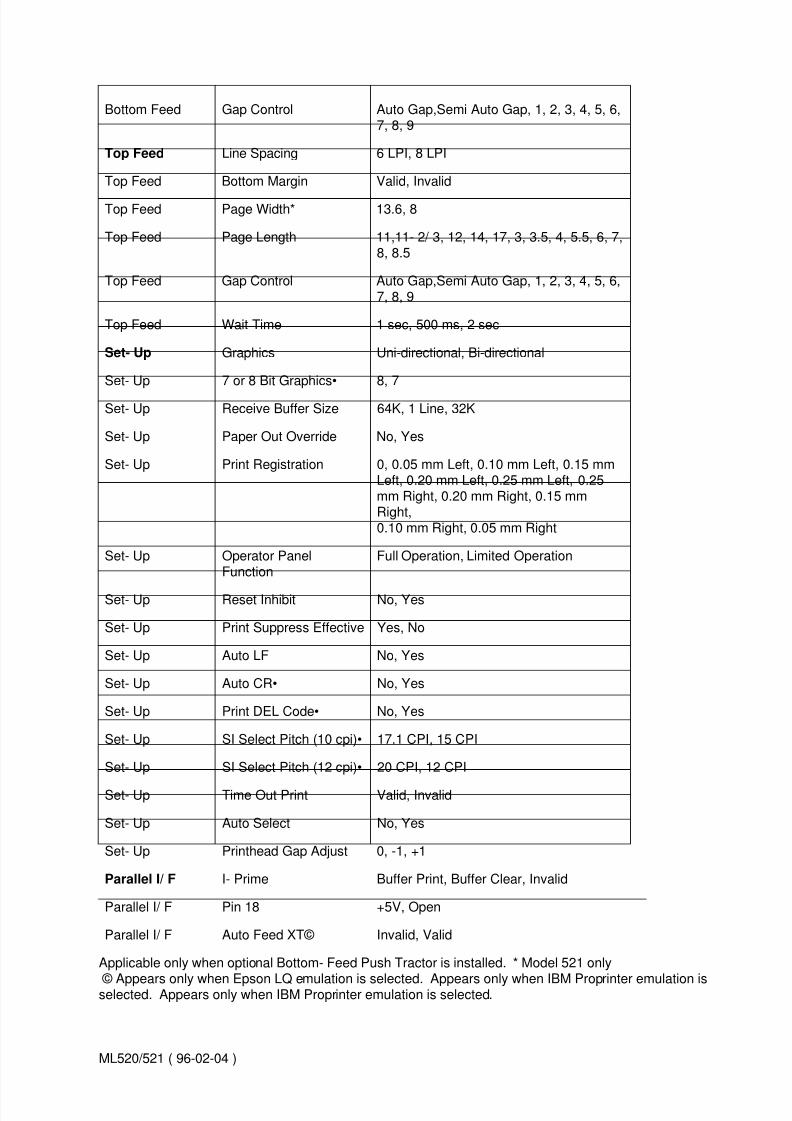
Summary of Menu Settings
The table below details all possible entries in the printer Menu. The defaults are the First Item in theSettings.
Group Item Settings
Printer Control Emulation Mode IBM PPR, Epson FX, ML
Font Print Mode Utility, NLQ Courier, NLQ Gothic, HSD
Font Pitch 10 cpi, 12 cpi, 15 cpi, 17.1 cpi, 20 cpi
Font Proportional spacing No,Yes
Font Style Normal,Italics
Font Size Single,Double
Symbol Sets Character Set Set I,Set II
Symbol Sets Language Set American,French, German, British,Danish I, Swedish, Italian, Spanish I,Japanese, Norwegian, Danish II,Spanish II, Latin American, FrenchCanadian, Dutch, Publisher
Symbol Sets Zero Character Slashed, Unslashed
Symbol Sets Code Page USA, Canada French, Multilingual,Portugal, Norway
Rear Feed Line Spacing 6 LPI, 8 LPI
Rear Feed Form Tear- Off Off, 500ms, 1 sec, 2 sec
Rear Feed Skip Over Perforation No, Yes
Rear Feed Page Width* 13.6, 8
Rear Feed Page Length 11,11- 2/ 3, 12, 14, 17, 3, 3.5, 4, 5.5,
6,7,8,8.5Rear Feed Gap Control Auto Gap,Semi Auto Gap, 1, 2, 3, 4, 5, 6,
7, 8, 9
Bottom Feed Line Spacing 6 LPI, 8 LPI
Bottom Feed Form Tear- Off Off, 500ms, 1 sec, 2 sec
Bottom Feed Skip Over Perforation No, Yes
Bottom Feed Page Width* 13.6, 8
Bottom Feed Page Length 11,11- 2/ 3, 12, 14, 17, 3, 3.5, 4, 5.5, 6, 7,
8, 8.5
ML520/521 ( 96-02-04 )
8/8/2019 MICROLINE® 520/521 Printer Handbook
http://slidepdf.com/reader/full/microline-520521-printer-handbook 40/47
Bottom Feed Gap Control Auto Gap,Semi Auto Gap, 1, 2, 3, 4, 5, 6,7, 8, 9
Top Feed Line Spacing 6 LPI, 8 LPI
Top Feed Bottom Margin Valid, Invalid
Top Feed Page Width* 13.6, 8
Top Feed Page Length 11,11- 2/ 3, 12, 14, 17, 3, 3.5, 4, 5.5, 6, 7,8, 8.5
Top Feed Gap Control Auto Gap,Semi Auto Gap, 1, 2, 3, 4, 5, 6,7, 8, 9
Top Feed Wait Time 1 sec, 500 ms, 2 sec
Set- Up Graphics Uni-directional, Bi-directional
Set- Up 7 or 8 Bit Graphics• 8, 7
Set- Up Receive Buffer Size 64K, 1 Line, 32K
Set- Up Paper Out Override No, Yes
Set- Up Print Registration 0, 0.05 mm Left, 0.10 mm Left, 0.15 mmLeft, 0.20 mm Left, 0.25 mm Left, 0.25mm Right, 0.20 mm Right, 0.15 mmRight,0.10 mm Right, 0.05 mm Right
Set- Up Operator PanelFunction
Full Operation, Limited Operation
Set- Up Reset Inhibit No, Yes
Set- Up Print Suppress Effective Yes, No
Set- Up Auto LF No, Yes
Set- Up Auto CR• No, Yes
Set- Up Print DEL Code• No, Yes
Set- Up SI Select Pitch (10 cpi)• 17.1 CPI, 15 CPI
Set- Up SI Select Pitch (12 cpi)• 20 CPI, 12 CPI
Set- Up Time Out Print Valid, Invalid
Set- Up Auto Select No, Yes
Set- Up Printhead Gap Adjust 0, -1, +1
Parallel I/ F I- Prime Buffer Print, Buffer Clear, Invalid
Parallel I/ F Pin 18 +5V, Open
Parallel I/ F Auto Feed XT© Invalid, Valid
Applicable only when optional Bottom- Feed Push Tractor is installed. * Model 521 only
© Appears only when Epson LQ emulation is selected. Appears only when IBM Proprinter emulation isselected. Appears only when IBM Proprinter emulation is selected.
ML520/521 ( 96-02-04 )

8/8/2019 MICROLINE® 520/521 Printer Handbook
http://slidepdf.com/reader/full/microline-520521-printer-handbook 41/47
Explanation of Menu Items
Explanation of Menu Items
These explanations are in alphabetical sequence. Line Spacing, Form Tear-Off, Skip Over Perforation,Page Length, and Gap Control appear several times in the menu.
7 or 8 Bit Graphics. Choose graphics your system uses: 7 or 8 (factory default) dots in each columnprinted.
Auto CR (IBM). If you wish to have the printer automatically add a carriage return when a Line Feed isreceived at the end of the line, change the setting to Yes.
Auto LF. If your printout is consistently double spaced, select No (factory default); if it overprints, chooseYes.
Auto Feed XT (Epson). If your system uses pin 14 of the parallel interface to control automatic line feed,
change the setting to Valid.
Auto Select. With the factory default (No) engaged, the printer will remain deselected after you load inpaper so that you can set the Top of Form. If you always use the same Top of Form setting, change thissetting to Yes.
Bottom Margin. Change the setting to Invalid if you want printer to ignore the bottom margin setting.Caution!! This can cause loss of data and damage the printhead.Character Set. Choose IBM Set I(factory default) or IBM Set II.
Code Page. Choose USA (factory default), Canada French, Multilingual, Portugal, or Norway.
Emulation Mode. Choose IBM PPR (default) for IBM Proprinter III, Epson FX, or ML for OKIDATAMicroline Standard.
Form Tear- Off. Choose 500ms, 1 sec, or 2 sec to turn this feature on and select a time interval for theprinter to wait before advancing the paper.
Gap Control. Determines how the printhead gap is set. Auto Gap automatically determines paperthickness on first page: for single sheets, it also rechecks each page while printing. Semi Auto Gap issimilar; but it does not recheck single sheets while printing. You can also choose a fixed headgap settingof 1 (narrowest) to 9 (widest).
Graphics. Change to bi-directional graphics for faster printing: optimize by the Print Registration settingin the Menu.
I- Prime. Sets what the printer does when it receives the I- Prime signal from software. Buffer Print(factory default): prints out buffer contents before resetting. Buffer Clear: dumps buffer contentsimmediately. Invalid: ignores I-Prime signal.
Language Set. Replaces certain symbols with special characters used in the respective foreignlanguage.Line Spacing. Change from 6 to 8 lpi (lines per inch) to get more lines per page.
Operator Panel Function. Change to Limited Operation to deactivate PRINT QUALITY andCHARACTER PITCH buttons when several people are using the printer and you don't want thesesettings changed from the control panel.
Note: This feature also prevents normal access to the Menu. To access the Menu, turn the printer off,
ML520/521 ( 96-02-04 )

8/8/2019 MICROLINE® 520/521 Printer Handbook
http://slidepdf.com/reader/full/microline-520521-printer-handbook 42/47
then hold down theSEL key while turning the printer on.
Page Length. Selects the length of the paper you're using.
Page Width (Model 521 only). Choose 8 for letter- size paper.
Paper Out Override. Senses when less than one inch of paper remains and stops printing. Choose Yesto override the detector. Caution!! This can cause loss of data and damage the printhead.
Pin 18. Sets the signal on pin 18 to +5V (factory default) or Open..
Pitch. Choose character width measured in characters per inch (cpi).
Print DEL Code (Microline Standard). Change to Yes if you wish to print the DEL code (decimal 127)as a solid box.
Print Mode. Choose NLQ Courier or NLQ Gothic font for letter quality printing, utility (factory default) forfaster draft printing, or HSD for fastest printing (lowest quality).
Print Registration. Change the setting as required to obtain the best registration for bi- directionalprinting.
Print Suppress Effective. If you system uses the DC1 and DC3 codes for something other than the printsuppress mode, change the setting to No.
Printhead Gap Adjust. Fine tunes the automatic setting of the printhead gap. If your printer isconsistently printing too light, change the setting to -1; if its too dark, change the setting to +1.
Proportional Spacing. Change the setting to Yes to engage proportional spacing of characters.
Receive Buffer Size. 64K (factory default), 1 Line, or 32K. Selects amount of memory devoted to holdingreceived data. 1 Line will tie up your computer while printing, but if you abort the print job, the printer willstop printing much sooner.
Reset Inhibit. Selecting Yes prevents your software from resetting your printers settings.
SI Select Pitch, 10 CPI (IBM only). Sets the pitch (17.1 the factory default or 15 characters per inch) tobe engaged when the printer control panel is set for 10 cpi and the SI command is received.
SI Select Pitch, 12 CPI (IBM only). Sets the pitch (20 the factory default or 12 characters per inch) to beengaged when the printer control panel is set for 12 cpi and the SI command is received.Size. Change toDouble for double width and height printing.
Skip Over Perforation. Change to Yes if you want the printer to go to the next page when it comeswithin 1 of the bottom. Keep it set to No if your software has its own page formatting controls.
Style. Change to Italics if you want the printed characters to be slanted.
Time Out Print. If your software spends a long time processing between portions of data it feeds to theprinter, change the setting to Invalid to keep your printer from inadvertently dumping the received datawhile it's waiting for more.
Wait Time. Sets the amount of time 500 ms, 1 sec (factory default), or 2 sec the printer will wait for moredata before moving to the form tear- off position.
Zero Character. If you dont wish the printer to use a slash to distinguish the number 0 from the capitalletter O, change the setting to Unslashed.
ML520/521 ( 96-02-04 )

8/8/2019 MICROLINE® 520/521 Printer Handbook
http://slidepdf.com/reader/full/microline-520521-printer-handbook 43/47
Chapter 6
Problem Solving
Problem Solving
Problem: Nothing happens when I turn on the printer.Solution: The printer may not be plugged in. Check the power cord connection to the outlet and to yourprinter. If you're using a power strip, make sure it's turned on. Check to be sure that the fuse hasn't blownor that the circuit breaker hasn't tripped.
Problem: The printer doesn't print when the computer sends data.Solutions: (1) The printer may be deselected. If the SEL light is out, press the SEL button to select theprinter.(2) The printer cable may not be securely connected. Check the cable to be sure that it is properlyconnected to both the PC and the printer.(3) If you have installed the serial I/ F board, it may not be firmlyseated. Check to be sure that the board is firmly seated in the printer.
Problem: I'm getting strange symbols, incorrect fonts, etc., when I try to print a document.Solution: The printer driver you have engaged does not agree with the emulation selected for yourprinter.To check the emulation selected, make sure paper is loaded, then press the SEL and SHIFTbuttons simultaneously to enter the MENU on your printer. Next, press the GROUP button: this will printthe emulation selected.If the emulation is not the one you want to use, press the SET button to change itto the one you want before exiting the MENU (to exit, press SEL and SHIFT buttons).If the emulation iscorrect, check your software documentation on how to select a printer driver, then check to be sure thatyou have selected one of the drivers listed for that emulation in Chapter 4( ). The closer the driver is tothe top of the list, the more compatible it will be with your printer. If your software doesn't have any of theindicated drivers available, check with the software manufacturer to see if they have added any additionaldrivers since you purchased your software.If you have embedded any printer commands in your
software, check to be sure that you entered them correctly.
Problem: I've installed a brand new ribbon and the printing is smeared and streaked.Solution: The plastic ribbon shield is either loose or missing. Move (caution printhead may be HOT!) the printhead to the center of the platen and lift off the ribbon cartridge. If the ribbon shield is loose,secure it in place properly. If it's missing, locate it and reinstall it.
Problem: I see printing on the right side of the page which is lighter or darker than the rest of the print.Solution: Although the printer automatically sets the head gap, it may sometimes need minoradjustment. To do this:1. Hold SHIFT button and press SEL button to enter Menu mode.2. Press GROUP button until Setup group prints.
3. Press ITEM button until Printhead Gap appears.4. Press SEL button to change setting. The default setting is 0. If the printing is sometimes lighter,change the setting to -1; if it's sometimes darker, change it to +1.5. Hold SHIFT button and press SEL button to save setting and exit Menu mode.
Problem: The Alarm light is on and the Character Pitch 15 light is flashing.Solution: This indicates a paper loading error. To stop the flashing light, press the SEL button. Beforetrying to load paper again, check to be sure that the paper lever is in the correct position (BOT, TOP,REAR) for the path you're using.If the paper lever is in the correct position and you're using rear feed, liftup the paper separator and check to be sure that the paper is properly on the tractors and has not jammed up.If the paper lever is in the correct position and you're using the optional bottom- feed pushtractor, check the bottom tractor unit to be sure that the paper is properly on the tractors and has not jammed up before entering the printer.Once the paper is correctly loaded, press and release the SEL
button, then hold the SHIFT button and press the RESET (Character Pitch) button.
ML520/521 ( 96-02-04 )

8/8/2019 MICROLINE® 520/521 Printer Handbook
http://slidepdf.com/reader/full/microline-520521-printer-handbook 44/47
Problem: The first line is printing too far down on the page and I can't get it any higher using the SHIFTand LF/MicroFeed Down buttons.Solution: The setting for the Top of Form (TOF) will be restricted if you have the Forms Tear- Off featureengaged when you set the TOF. To correct for this, you must reset the TOF with the Forms Tear- Offdisengaged, as follows:1. Hold SHIFT button and press SEL button to enter Menu mode.
2. Use GROUP and ITEM buttons to reach Rear Feed Form Tear- Off entry and/ or Bottom Feed FormTear- Off entry, depending on paper path( s) you're using.3. Use SET button to change Form Tear- Off setting to Off.4. Hold SHIFT button and press SEL button to exit Menu mode.5. Press SEL button to deselect printer.6. Hold SHIFT button while pressing LF/ Micro Shift Down button to set TOF at desired position.7. Hold SHIFT button and press SEL button to enter Menu mode.8. Use GROUP and ITEM buttons to reach Rear Feed Form Tear- Off entry and/ or Bottom Feed FormTear- Off.9. Use SET button to change Form Tear- Off to desired setting (500ms, 1 sec or 2 sec).10. Hold SHIFT button and press SEL button to exit Menu mode.
Problem: I need to load paper, but the Alarm light is not on and I cant load paper.Solution: If the Alarm light is off, the printer thinks it has paper loaded. To correct this problem, pressand release the SEL button, then hold the SHIFT button and press the RESET (Character Pitch) button.The Alarm light will come on and you'll be able to load paper.
Problem: My word processor files don't print the way I have the MENU and front panel set.Solution: Before sending a file to the printer, many word processors send either an initialization string oran I- Prime signal to the printer. The initialization string contains codes that reset the printer to a defaultset of features: otherwise the printer might accidentally print using features set for a previous job. Thesecodes override panel or MENU settings. To set your printer to ignore the reset code, enter the printerMENU (hold SHIFT button while pressing SEL/ MENU button) and change the Reset Inhibit item (in theSet- Up group) to Yes. Please note that while this will stop the reset code from resetting your printer,other codes in the initialization string may still override the printer MENU and/ or front panel settings. TheI- Prime signal is sent over the parallel interface (pin 31) and will automatically override any settings youhave made using the front panel buttons. To eliminate this problem, enter the program MENU (holdSHIFT button while pressing SEL/ MENU button) and change the I- Prime item (in the Parallel I/ F group)to Invalid.
Problem: The Print Quality and Character Pitch buttons on the front panel won't work.Solution: The Operator Panel Function item on the printer MENU can be used to disable these buttons.If the printer is part of a customized system or if it is used by a number of people, the system managermay have used this option to make sure the printer is always set properly.
Problem: Static electricity causes the paper to stick.Solution: In cold, dry weather, static charges can build that make the paper cling to the paper separator.
Try moving the single sheet paper guides on the separator together so that the paper rests on the guidesrather than on the separator itself. Problem Solving & Maintenanc
ML520/521 ( 96-02-04 )

8/8/2019 MICROLINE® 520/521 Printer Handbook
http://slidepdf.com/reader/full/microline-520521-printer-handbook 45/47
Maintenance Cleaning the Housing
Maintenance Cleaning the Housing
You should clean the printer every six months (or after about 300 hours of operation).Turn the printerOFF and remove the paper from the path. Open the access cover and remove the pull- up rollerassembly ( 1 ). Use a clean, dry cloth to dust the area around the carriage shaft and platen( 2 ). Be sure to remove any loose particles of paper. Reinstall the pull- up roller assembly and close theaccess cover.
Note: Never use solvents or strong detergents on the cabinet they could damage the housing.
ML520/521 ( 96-02-04 )

8/8/2019 MICROLINE® 520/521 Printer Handbook
http://slidepdf.com/reader/full/microline-520521-printer-handbook 46/47
Appendix A
Specifications
Printhead 9 pins, 0.34 mm diameter, automatically adjusting to paper thickness, with thermal protection
Print Speed Mode Characters per second at 10 CpiHigh Speed Draft (HSD) 427 cpsUtility 320 cpsNear Letter Quality (NLQ) 80 cps
Characters per Line (CPL) Setting ML520 ML52110 cpi 80 cpl 136 cpl12 cpi 96 cpl 163 cpl15 cpi 120 cpl 204 cpl17.1 cpi 137 cpl 233 cpl20 cpi 160 cpl 272 cpl
Emulations Epson FX, IBM Proprinter, and OKIDATA Microline Standard co-resident
Interface Standard: Centronics parallelOptional: RS- 232C serial
Graphics Resolution Emulation ResolutionEpson/ IBM Single Density: 144 ´ 240 dpi
Double Density: 120 ´ 144 dpiQuadruple Density: 72 ´ 120 dpi
OKIDATA Microline Standard Single Density: 144 ´ 288 dpi
Double Density: 144 ´ 144 dpiQuadruple Density: 72 ´ 72 dpi
Resident Fonts Print Quality Available FontsNear Letter Quality Courier, GothicUtility GothicHigh Speed Draft Gothic
Bar Codes Code 39, UPC A, UPC E, EAN 8, EAN 13, Interleaved 2 of 5, Code 128 (A, B, and C),Postnet
Receive Buffer Size 64K
Reliability Parameter ReliabilityMean Time Between Failures (MTBF) 6000 hours at 25% duty cycle and 35% page
densityMean Time to Repair (MTTR) 15 minutesPrinthead life 200 million characters average in 10 cpi utility
mode at 25%duty and 35% page density
Ribbon Life (on average, 10 cpi utility) 4 million characters
Paper Width Minimum: 3 Maximum: Model 520, 10 Model 521, 16
Paper Weight 12 to 24 lb.
Paper Thickness Rear feed: 0.014 (0.36 mm) Bottom feed: 0.017 (0.44 mm)
ML520/521 ( 96-02-04 )

8/8/2019 MICROLINE® 520/521 Printer Handbook
http://slidepdf.com/reader/full/microline-520521-printer-handbook 47/47
Paper Specifications
Dimensions (W ´ ´ D ´ ´ H)Model 520: 17 ´ 15 ´ 6½ inches (431 ´ 380 ´ 166 mm) Model521: 23 ´ 15 ´ 6½ inches (585 ´ 380 ´ 166 mm)
Weight Model 520: 17 lb. 10 oz. (8 kg)Model 521: 23 b. 2 oz. (10.5 kg)
Environmental Requirements Parameter RangeOperating Temperature 41 to 104° F (5 to 40° C)Storage Temperature 14 to 122° F (- 10 to +50° C)
Operating Humidity 20 to 80% RHStorage Humidity 5 to 95% RH
Electrical requirements 120 volts ac (+ 5.5%, -15%), 60 Hz (± 2%) Also available for 230 (+ 6%,- 10%)volts ac or 240 (+ 10%) volts ac, 50/ 60 Hz ( ±2%)
Specifications subject to change without notice.