MICROHOLE SMART STEERING AND LOGGING WHILE …/67531/metadc885868/m2/1/high... · A background to...
44
1 Baker Hughes Oilfield Operations, 3900 Essex Lane, Suite 1200, Houston, Texas, 77027 MICROHOLE SMART STEERING AND LOGGING WHILE DRILLING SYSTEM PROJECT FINAL TECHNICAL REPORT Report Period Start Date: October 1, 2004 Report Period End Date: June 30, 2006 Authors: John Macpherson Mathias Moeller Thomas Gregg Roland Chemali REPORT DATE: JULY 2006 DOE AWARD NUMBER: DE-FC26-04NT15473 Baker Hughes Oilfield Operations, Inc. 3900 Essex lane, Suite 1200, Houston, Texas 77027-5170
Transcript of MICROHOLE SMART STEERING AND LOGGING WHILE …/67531/metadc885868/m2/1/high... · A background to...

1 Baker Hughes Oilfield Operations, 3900 Essex Lane, Suite 1200, Houston, Texas, 77027
MICROHOLE SMART STEERING AND
LOGGING WHILE DRILLING SYSTEM
PROJECT FINAL TECHNICAL REPORT
Report Period Start Date: October 1, 2004 Report Period End Date: June 30, 2006 Authors: John Macpherson
Mathias Moeller Thomas Gregg Roland Chemali
REPORT DATE: JULY 2006
DOE AWARD NUMBER: DE-FC26-04NT15473
Baker Hughes Oilfield Operations, Inc. 3900 Essex lane, Suite 1200, Houston, Texas 77027-5170
2
Baker Hughes Oilfield Operations, 3900 Essex Lane, Suite 1200, Houston, Texas, 77027
DISCLAIMER
This report was prepared as an account of work sponsored by an agency of the United
States Government. Neither the United States Government, nor any of their employees, makes any warranty, express or implied, or assumes any legal liability or responsibility for the accuracy, completeness, or usefulness of any information, apparatus, product, or process disclosed, or represents that its use would not infringe owned rights. Reference
herein to any specific commercial product, process, or service by trade name, trademark, manufacturer, or otherwise does not necessarily constitute or imply its endorsement,
recommendation, or favoring by the United States Government or any agency thereof. The views and opinions of authors expressed herein do not necessarily state or reflect
those of the United States Government or any agency thereof.

3
Baker Hughes Oilfield Operations, 3900 Essex Lane, Suite 1200, Houston, Texas, 77027
Abstract A background to Coiled Tubing Bottom Hole Assemblies (CT-BHA) is given, and the development of a resistivity measurement component, and a rib-steering motor component, is described. The successful operation of these components in both the laboratory and field environment is described. The primary conclusion of this development is that both components operate as anticipated within the CT-BHA, and significantly extend the possibility of drilling with coiled tubing in the microhole environment.
Table of Contents ABSTRACT .................................................................................................................................................. 3 TABLE OF CONTENTS............................................................................................................................. 3 EXECUTIVE SUMMARY .......................................................................................................................... 4 BACKGROUND........................................................................................................................................... 6
COILED TUBING DRILLING ......................................................................................................................... 6 System Design Approach ...................................................................................................................... 8
RESULTS AND DISCUSSIONS............................................................................................................... 10 RIB-STEERING MOTOR (RSM) MODULE .................................................................................................. 10
Laboratory Testing, 2-3/8” RSM ........................................................................................................ 13 MULTIPLE PROPAGATION RESISTIVITY (MPR) MODULE.......................................................................... 21
Laboratory Testing, 2 3/8” MPR ........................................................................................................ 24 FIELD TESTING ......................................................................................................................................... 31
BHA integration.................................................................................................................................. 31 Field Test Objectives........................................................................................................................... 31 Field Testing, 2-3/8” RSM.................................................................................................................. 32 Field Testing, 2-3/8” MPR.................................................................................................................. 33 Drilling Conditions ............................................................................................................................. 35 Field Test Performance....................................................................................................................... 36 Post Field Test Analysis, 2-3/8” MPR ................................................................................................ 37
CONCLUSIONS......................................................................................................................................... 40 APPENDIX A: FIELD TEST WELL SECTIONS.................................................................................. 42 APPENDIX B: COMPARISON 2-3/8” RSM WITH 2-3/8” CONVENTIONAL ................................. 42
4
Baker Hughes Oilfield Operations, 3900 Essex Lane, Suite 1200, Houston, Texas, 77027
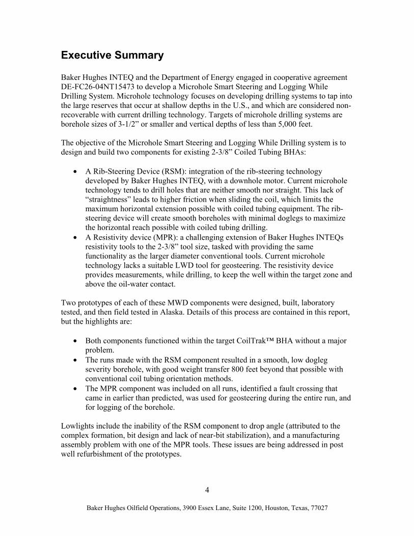
Executive Summary Baker Hughes INTEQ and the Department of Energy engaged in cooperative agreement DE-FC26-04NT15473 to develop a Microhole Smart Steering and Logging While Drilling System. Microhole technology focuses on developing drilling systems to tap into the large reserves that occur at shallow depths in the U.S., and which are considered non-recoverable with current drilling technology. Targets of microhole drilling systems are borehole sizes of 3-1/2” or smaller and vertical depths of less than 5,000 feet. The objective of the Microhole Smart Steering and Logging While Drilling system is to design and build two components for existing 2-3/8” Coiled Tubing BHAs:
• A Rib-Steering Device (RSM): integration of the rib-steering technology developed by Baker Hughes INTEQ, with a downhole motor. Current microhole technology tends to drill holes that are neither smooth nor straight. This lack of “straightness” leads to higher friction when sliding the coil, which limits the maximum horizontal extension possible with coiled tubing equipment. The rib-steering device will create smooth boreholes with minimal doglegs to maximize the horizontal reach possible with coiled tubing drilling.
• A Resistivity device (MPR): a challenging extension of Baker Hughes INTEQs resistivity tools to the 2-3/8” tool size, tasked with providing the same functionality as the larger diameter conventional tools. Current microhole technology lacks a suitable LWD tool for geosteering. The resistivity device provides measurements, while drilling, to keep the well within the target zone and above the oil-water contact.
Two prototypes of each of these MWD components were designed, built, laboratory tested, and then field tested in Alaska. Details of this process are contained in this report, but the highlights are:
• Both components functioned within the target CoilTrak™ BHA without a major problem.
• The runs made with the RSM component resulted in a smooth, low dogleg severity borehole, with good weight transfer 800 feet beyond that possible with conventional coil tubing orientation methods.
• The MPR component was included on all runs, identified a fault crossing that came in earlier than predicted, was used for geosteering during the entire run, and for logging of the borehole.
Lowlights include the inability of the RSM component to drop angle (attributed to the complex formation, bit design and lack of near-bit stabilization), and a manufacturing assembly problem with one of the MPR tools. These issues are being addressed in post well refurbishment of the prototypes.

5
Baker Hughes Oilfield Operations, 3900 Essex Lane, Suite 1200, Houston, Texas, 77027
Baker Hughes INTEQ intends to run these prototypes again, to gain operating time and footage. It will then re-evaluate the design in 2007, and make a decision on full commercialization of these components. U.S. Department of Energy participation in funding of this project has been critical to its success. Without this participation, it is likely that there would have been significant delays in the development of these BHA components for microhole drilling.

6
Baker Hughes Oilfield Operations, 3900 Essex Lane, Suite 1200, Houston, Texas, 77027
Background The technology developed in this cooperative agreement targeted the specific problem of insufficient steering accuracy and borehole quality in very slim borehole sizes. For the drilling of 3-½” or smaller diameter development wells, coiled tubing technology offers many benefits over rotary drilling. However, since Coiled Tubing Drilling (CTD) is a niche market, service companies are restricted in funds for new coiled tubing bottom-hole assembly (BHA) development. A typical state of the art coiled tubing BHA uses a downhole mud motor with adjustable kick-off sub (AKO) and electric motor driven angle adjustment device. The AKO steerable motor system is used to kick off from the previous vertical well into the build section. However, with horizontal or near-horizontal 3-½” or smaller legs, such a BHA tends to produce a non-steady borehole curvature. This results in considerable doglegs and borehole tortuosity, which in turn leads to higher friction when sliding the coil and thus limits the maximum horizontal extension possible with such equipment. The rib-steering motor component developed as part of this project overcomes this constraint by providing a more appropriate steering device that is capable of drilling smooth straight borehole sections. Also, absent in the currently available CTD bottom hole assemblies for the 3-½” borehole size is a suitable formation evaluation, or logging while drilling, device. In order to steer the well trajectory along the oil-water interface, resistivity measurements taken during the drilling process within the target zone can provide instantaneous information about the distance to the water boundary. Thus, it is possible to orient the borehole trajectory for optimal recovery, with minimum risk of water invasion. Furthermore, without the inclusion in the BHA of formation evaluation sensors, it is not possible to detect trapped hydrocarbons along the well path. The resistivity component developed as part of this project overcomes this constraint by providing a 2-3/8” outside diameter tool that can fit into the 3-1/2” borehole.
Coiled Tubing Drilling Coiled tubing drilling is in general a proven and mature technology that competes successfully against conventional rotary drilling, if the technical and economical aspects of the application fit the characteristics of the coiled tubing system.
“In 1991, open-hole drilling with coiled tubing (except for some work performed in the 1970s) began. The number of wells drilled with coiled tubing since those three initial wells in 1991 has increased sharply. Though the numbers of wells

7
Baker Hughes Oilfield Operations, 3900 Essex Lane, Suite 1200, Houston, Texas, 77027
involved is still relatively small compared to the total drilling market, the potential of CT drilling makes it a very exciting service.”1
Baker Hughes INTEQ has had a long tradition in developing, manufacturing and operating coiled tubing drilling assemblies since the early 90s of the last century. In 1991 Baker Hughes INTEQ actually started the research and development, and field trials, of the world’s first E-line CT drilling prototype BHA system, called OrientXPress (OXP), and this evolved into the current CoilTrak™ BHA system. Over the years, INTEQ has developed the industry standard for CT drilling and has gained valuable experience in major worldwide re-entry drilling projects, both in under balanced and overbalanced drilling. The following are a few of INTEQ’s Coiled Tubing Drilling milestones: 1992 First pilot series run to verify concept of CT orienting tool 1995 OrientXPress successfully drilled well at 265°F (130 C) in Holland 1998 Development of ultra slim (3 1/8”) resistivity (MPR) for CT Drilling 1999 Successfully ran first commercial Ultra Slim LWD geosteering 2000 Record longest horizontal section drilled with CT in Oman of 4,677 ft (1,425 m). 2001 Initial field tests of first E-line operated 2 3/8” CoilTrak 2002 Introduction of the 2 3/8” CoilTrak and 2 3/8” X-treme motors 2003 Introduction of the 3” CoilTrak in UB two-phase flow and 300°F (150 C)
downhole temperature Even though there are other vendors of coiled tubing drilling bottom-hole assemblies, Baker Hughes INTEQ (BHI) is the leading provider of such equipment and services. BHI through the last 10 years has moved from its early OrientXPress™ to the state-of-the-art modular CoilTrak™ system. The CoilTrak™ BHA system is designed to both drill and evaluate holes. CoilTrak™ comes in two sizes: 2-3/8” and 3”. The first size is used to drill a 2-¾” – 3-½” hole, whereas the latter size is for the 3-½” to 4-¾” hole size. The bottom-hole assembly, which transmits data on a wireline inside the coiled tubing, can measure directional, gamma ray and temperature data. Additional features can include weight on bit, annular and bore pressure. Baker Hughes markets the NaviDrill® motor in different versions for CTD applications.2 In both cases, downhole steering is accomplished by means of a mud motor with integrated adjustable kick-off (AKO) sub. A 3-1/8” ultra-slim multi-propagation
1 Ken Newman, World Oil, Jan. 1998
2 U.S. Department of Energy, Microdrill Initiative, Initial Market Evaluation, Prepared by Spears &
Associates, Inc., 5110 South Yale, Suite 410, Tulsa, OK 74135

8
Baker Hughes Oilfield Operations, 3900 Essex Lane, Suite 1200, Houston, Texas, 77027
resistivity (US MPR) formation evaluation sub is available for the larger tool size version only.
System Design Approach
The two drill string elements developed under this project are not stand-alone units that work by themselves. On the contrary, they fit seamlessly into an existing, already commercialized, modular coiled tubing drilling bottom-hole assembly (figure 1).
Figure 1: Outline of commercially available 2-3/8” CoilTrak™ bottom hole assembly
The BHA shown in figure 1 communicates with the surface by high speed, bi-directional electric line (e-line). Below the coil connector at the top of the BHA is the Upper Quick Connect (UQC) sub, followed by the power and communication sub, with the Casing Collar Locator (CCL) for depth location. The EDC sub (electrical disconnect and circulating sub) provides the capability of bypassing fluid flow to the annulus multiple times on electrical command from the surface, or a single use electrical disconnect of the lower BHA components. The lower BHA components can consist of a drilling performance sub with pressure sensors and downhole weight-on-bit measurement (DWOB), a directional and gamma-ray measurement sub, and orienting components. The orienting components consist of a hydraulic orienting tool with hydraulic power delivered from an overlying sub with near-bit inclination (NBI) and tool-face indicator (TFI). Bit rotation is developed in an X-treme™ AKO mud motor immediately above the bit.
rotation
2.3/8” X - TREME Motor
Hydraulic Orienting Tool
Power & Comm. Sub w/ CCL
Coil Connector
UQC w/ cable anchor & flapper valve
Hydraulic Power Control Sub w/ NBI/TFI- Sensor
Directional & Gamma Sub
bi-directional
Electrical Disconnect & Circ. SubPressure Sensors& DWOB Sub

9
Baker Hughes Oilfield Operations, 3900 Essex Lane, Suite 1200, Houston, Texas, 77027
The system shown above is commercially available from Baker Hughes INTEQ3. The main application area has been the “North Slope” in Alaska, and the system has drilled several thousand feet since its introduction in 2002. Both the Rib-Steering Motor (RSM) and the Resistivity module (MPR) can be added to the BHA when required at the rig site. The RSM replaces the AKO Motor and the Hydraulic Orienting Tool. The existing Hydraulic Power Control Sub provides hydraulic control of the RSM. The Resistivity Sub is just another electronic module that communicates via the system bus structure with the Directional and Gamma Sub. The new BHA is shown in figure 2:
Figure 2: New CoilTrak™ 2 3/8” BHA with Rib Steering Motor and Resistivity module
In summary, the two new modules provide the system with the capability to better develop a reservoir through more precise steering, and through better measurement of formation properties.
3 2 3/8 CoilTrak™ Technical Data Sheet, Baker Hughes Incorporated, CTK-20-60-0238-00-07
Coil Connector
UQC Ball Valve Sub
Directional & Gamma Sub
Drilling Performance
Sub
Elec. Disconnect& Circulating Sub
Hydraulic Power ControlSub w/ NBI/TFI Sensor
Rib Assisted Motor (RAM)
Power&Comm. Sub
Resistivity Sub
Coil Connector
UQC Ball Valve Sub
Directional & Gamma Sub
Drilling Performance
Sub
Elec. Disconnect& Circulating Sub
Hydraulic Power ControlSub w/ NBI/TFI Sensor
Rib Assisted Motor (RAM)
Power&Comm. Sub
Resistivity Sub
10
Baker Hughes Oilfield Operations, 3900 Essex Lane, Suite 1200, Houston, Texas, 77027
Results and Discussions The development of the two modules, the rib-steering motor (RSM) and the Multiple Propagation Resistivity (MPR) module, is amply described in the quarterly reports that document the project. This section of the Final Technical Report simply describes these two components in some detail, and describes the laboratory testing and field-testing that concluded the project.
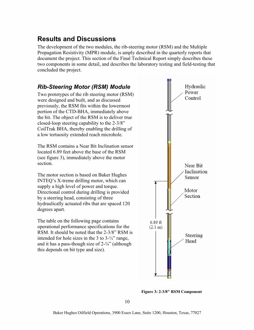
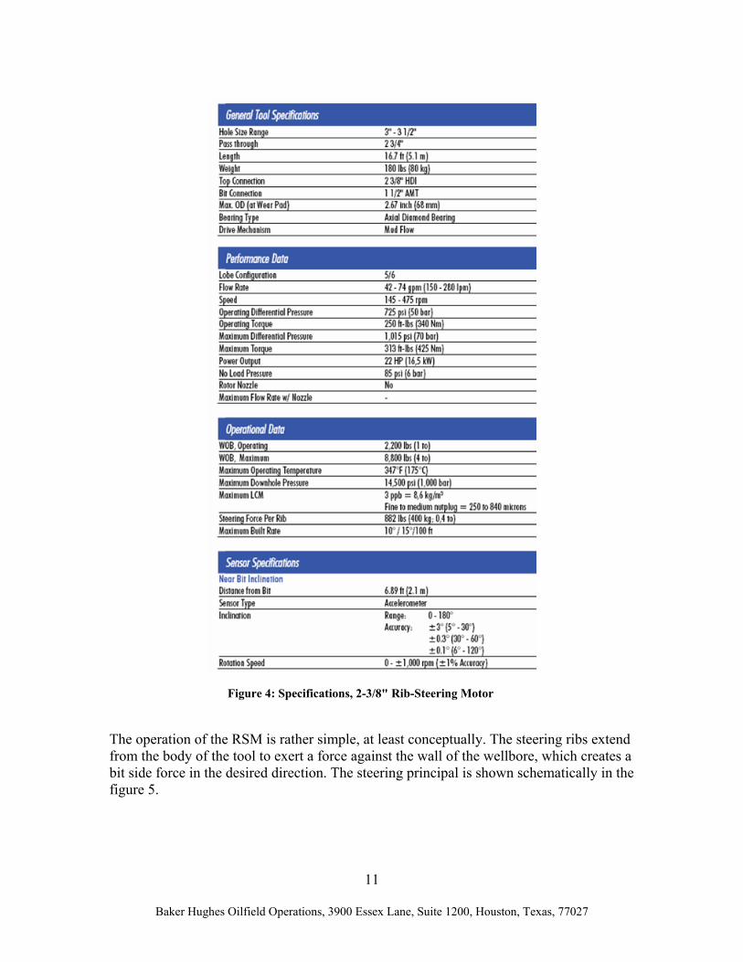
Rib-Steering Motor (RSM) Module Two prototypes of the rib steering motor (RSM) were designed and built, and as discussed previously, the RSM fits within the lowermost portion of the CTD-BHA, immediately above the bit. The object of the RSM is to deliver true closed-loop steering capability to the 2-3/8” CoilTrak BHA, thereby enabling the drilling of a low tortuosity extended reach microhole. The RSM contains a Near Bit Inclination sensor located 6.89 feet above the base of the RSM (see figure 3), immediately above the motor section. The motor section is based on Baker Hughes INTEQ’s X-treme drilling motor, which can supply a high level of power and torque. Directional control during drilling is provided by a steering head, consisting of three hydraulically actuated ribs that are spaced 120 degrees apart. The table on the following page contains operational performance specifications for the RSM. It should be noted that the 2-3/8” RSM is intended for hole sizes in the 3 to 3-½” range, and it has a pass-though size of 2-¾” (although this depends on bit type and size).
Figure 3: 2-3/8" RSM Component
11
Baker Hughes Oilfield Operations, 3900 Essex Lane, Suite 1200, Houston, Texas, 77027
The operation of the RSM is rather simple, at least conceptually. The steering ribs extend from the body of the tool to exert a force against the wall of the wellbore, which creates a bit side force in the desired direction. The steering principal is shown schematically in the figure 5.
Figure 4: Specifications, 2-3/8" Rib-Steering Motor

12
Baker Hughes Oilfield Operations, 3900 Essex Lane, Suite 1200, Houston, Texas, 77027
In figure 6, the steering ribs of the 2-3/8” RSM are fully retracted, and extended by 8mm. Since an e-line connects the downhole hydraulic control unit with the surface control system, borehole trajectory comes under tight directional control with this system. This reduces borehole tortuosity (borehole tortuosity is an unpleasant fact when drilling with bent motors) which results in reduced borehole friction and extended reach microholes.
Figure 5: RSM steering principal
Figure 6: RSM ribs retracted (upper) and extended by 8mm (lower).

13
Baker Hughes Oilfield Operations, 3900 Essex Lane, Suite 1200, Houston, Texas, 77027
Laboratory Testing, 2-3/8” RSM
Laboratory testing of the 2-3/8” Rib Steering Motor were conducted at the Baker Hughes INTEQ flow loop in Celle, Germany, prior to field deployment. Laboratory testing of the RSM had the following goals:
• confirm integration with existing CoilTrak™ BHA components
• confirm the functionality of the steering mechanism and algorithm
• confirm the mechanical integrity of all new components
• determine the maximum BUR of the system
• determine the maximum BUR with 3” bi-center bit (required for field test)
• verify the calculated BUR
• estimate drag from the steering ribs
• measure the motor performance of the RSM
• verify the calculated motor performance
Obtaining this information required three different tests: a concrete drilling test, a performance test, and a high pressure / high temperature test.
Concrete Drilling Test The RSM drilled five holes into concrete blocks, to verify system performance. The concrete blocks, 16.4 x 2.0 x 2.3 feet (5m x 0.6m x 0.7m), were cast in B35 quality concrete, which corresponds to a compressive strength of 5000 psi (35 N/mm^2). A four-foot (1.2 m) long, flanged tube was bolted to the concrete block to provide initial guidance for the bit, and to serve as a drainpipe for fluid returns. The BHA was aligned horizontally between the concrete block and a hydraulic ram that supplied a constant feed – rate of penetration – of 17.1 ft/hr (87 mm/min). The following parameters varied during the drilling tests:
• Flow rate (slowly increased to 66 gpm – 250 l/min – for stable drilling conditions)
• Motor current (3 different settings to identify influence on BUR)
• Tool face (to verify automatic correction in steering modes)
• Steering mode (“inclination hold” and “steer” modes)

14
Baker Hughes Oilfield Operations, 3900 Essex Lane, Suite 1200, Houston, Texas, 77027
Figure 7: Drilling test on the Baker Hughes INTEQ flow loop, Celle, Germany
The CoilTrak™ (CTK) tool was configured as follows during the concrete block drilling tests (see figure 8):
• 3” shortened bit (a 3”x 2.7” DOSTRWD324 – bi-center – bit was used in the last
run for comparison)
• 2 3/8” RSM with steering ribs for 3” hole size, and wear pad for 2 ¾” restrictions
• 2 3/8” DGS (Directional Gamma Sub) for tool face and inclination measurements
• 2 3/8” DPS (Drilling Performance Sub) for pressure and WOB measurements
• 2 3/8” EDC (Electrical Disconnect and Circulating Sub) to create additional
length to drill two blocks (10m)
• Side entry sub with feed-through for power and communication line (M30)
• Power and Control lab test box connected to tool by the M30 line.
Concrete block
Frame
CTK tool
Flow line
Hydraulic ram
15
Baker Hughes Oilfield Operations, 3900 Essex Lane, Suite 1200, Houston, Texas, 77027
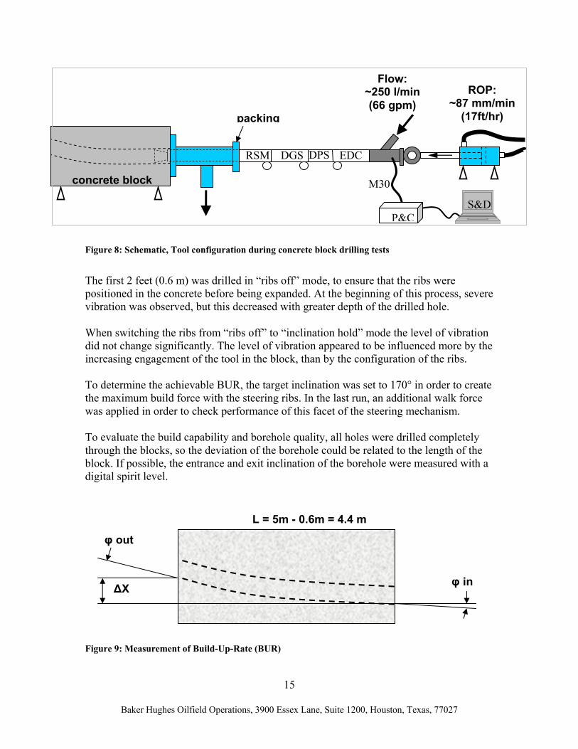
Figure 8: Schematic, Tool configuration during concrete block drilling tests
The first 2 feet (0.6 m) was drilled in “ribs off” mode, to ensure that the ribs were positioned in the concrete before being expanded. At the beginning of this process, severe vibration was observed, but this decreased with greater depth of the drilled hole. When switching the ribs from “ribs off” to “inclination hold” mode the level of vibration did not change significantly. The level of vibration appeared to be influenced more by the increasing engagement of the tool in the block, than by the configuration of the ribs. To determine the achievable BUR, the target inclination was set to 170° in order to create the maximum build force with the steering ribs. In the last run, an additional walk force was applied in order to check performance of this facet of the steering mechanism. To evaluate the build capability and borehole quality, all holes were drilled completely through the blocks, so the deviation of the borehole could be related to the length of the block. If possible, the entrance and exit inclination of the borehole were measured with a digital spirit level.
Figure 9: Measurement of Build-Up-Rate (BUR)
RSM DPS DGS
M30
EDC
Flow: ~250 l/min (66 gpm)
ROP: ~87 mm/min
(17ft/hr) packing
concrete block
P&CS&D
∆X
L = 5m - 0.6m = 4.4 m
φ out
φ in

16
Baker Hughes Oilfield Operations, 3900 Essex Lane, Suite 1200, Houston, Texas, 77027
Calculation of the build angle (ϕ) and build up rate (BUR) was as follows:
∆= −
LX1tan2ϕ
ftL
BUR 100deg/,932.65.30 ϕϕ ==
Concrete Drilling Test 1: 16.4 feet (5 m) Jan-30-06 Motor current: 2000 mA max. Pump rate: 66 gpm (250l/min) Diff. pressure ca. 508 psi (35 bar) Start: 88.0° inclination Position: 5.79 in (147mm) Exit: 93.1° inclination Position: 9.65 in (245mm) Delta: 5.1° inclination Height: 3.86 in (98 mm) ϕ = 2.5º Calculated BUR = 17.7 º /100ft With one or two ribs switched on, ROP was low and WOB would increase slightly. When all ribs were switched off (with only low pressure used to expand the ribs to the borehole wall), the ROP would suddenly increase and the WOB would drop. The decision was made, therefore, to decrease the high-pressure level of the hydraulic system by lowering the current limitation from 2000 mA to 750 mA. In the beginning a lever and a load cell were attached to the BHA to measure reactive torque, but due to the limited ROP the torque was so low, 44 ft-lbf (60 Nm) that the BHA could be held by friction alone. Concrete Drilling Test 2: 16.4 feet (5 m) Jan-31-06 Motor current: 750 mA max Pump rate: 66 gpm (250l/min) 440 rpm Diff. pressure: ca. 435 psi (30 bar) – possibly lower side loads Drilling straight for 3 feet (1m), then building with inclination hold set to 170° Start: 89.5° inclination Position: 6.22 in (158mm) Exit: 92.6° inclination Position: 9.72 in (247mm) Delta: 5.1° inclination Height: 3.5 in (89 mm)
17
Baker Hughes Oilfield Operations, 3900 Essex Lane, Suite 1200, Houston, Texas, 77027
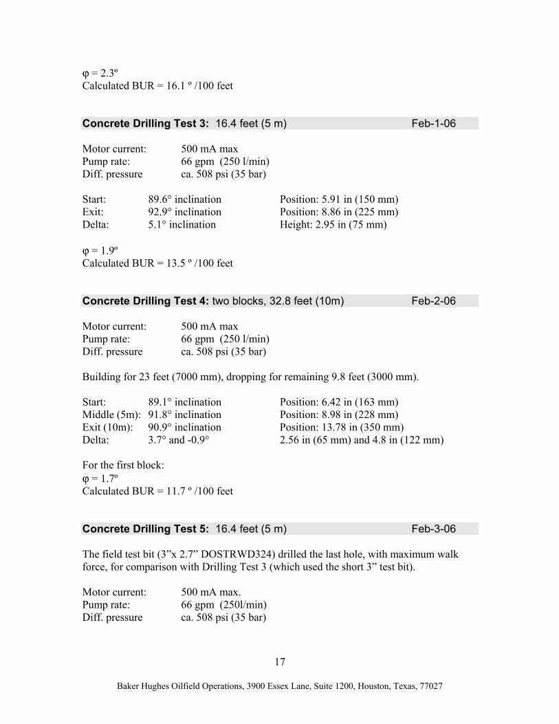
ϕ = 2.3º Calculated BUR = 16.1 º /100 feet Concrete Drilling Test 3: 16.4 feet (5 m) Feb-1-06 Motor current: 500 mA max Pump rate: 66 gpm (250 l/min) Diff. pressure ca. 508 psi (35 bar) Start: 89.6° inclination Position: 5.91 in (150 mm) Exit: 92.9° inclination Position: 8.86 in (225 mm) Delta: 5.1° inclination Height: 2.95 in (75 mm) ϕ = 1.9º Calculated BUR = 13.5 º /100 feet Concrete Drilling Test 4: two blocks, 32.8 feet (10m) Feb-2-06 Motor current: 500 mA max Pump rate: 66 gpm (250 l/min) Diff. pressure ca. 508 psi (35 bar) Building for 23 feet (7000 mm), dropping for remaining 9.8 feet (3000 mm). Start: 89.1° inclination Position: 6.42 in (163 mm) Middle (5m): 91.8° inclination Position: 8.98 in (228 mm) Exit (10m): 90.9° inclination Position: 13.78 in (350 mm) Delta: 3.7° and -0.9° 2.56 in (65 mm) and 4.8 in (122 mm) For the first block: ϕ = 1.7º Calculated BUR = 11.7 º /100 feet Concrete Drilling Test 5: 16.4 feet (5 m) Feb-3-06 The field test bit (3”x 2.7” DOSTRWD324) drilled the last hole, with maximum walk force, for comparison with Drilling Test 3 (which used the short 3” test bit). Motor current: 500 mA max. Pump rate: 66 gpm (250l/min) Diff. pressure ca. 508 psi (35 bar)
18
Baker Hughes Oilfield Operations, 3900 Essex Lane, Suite 1200, Houston, Texas, 77027
100% build force (x-direction), 100% walk force (y-direction) Start: 88.6° inclination x-Position: 5.24 in (133 mm), y-Position: 15.04 in (382 mm) Exit: no meas. value x-Position: 6.10 in (155 mm),y-Position: 16.34 in (349 mm) Delta: x = 22mm, y = 33mm s= 40mm (s² = x² +y²)
Calculated Dogleg,
= −
Ls1tan2ϕ , 7.2 º /100 feet
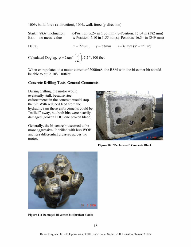
When extrapolated to a motor current of 2000mA, the RSM with the bi-center bit should be able to build 10º/ 100feet. Concrete Drilling Tests, General Comments During drilling, the motor would eventually stall, because steel enforcements in the concrete would stop the bit. With reduced feed from the hydraulic ram these enforcements could be “milled” away, but both bits were heavily damaged (broken PDC, one broken blade). Generally, the bi-centre bit seemed to be more aggressive. It drilled with less WOB and less differential pressure across the motor.
Figure 11: Damaged bi-center bit (broken blade)
Figure 10: "Perforated" Concrete Block
19
Baker Hughes Oilfield Operations, 3900 Essex Lane, Suite 1200, Houston, Texas, 77027
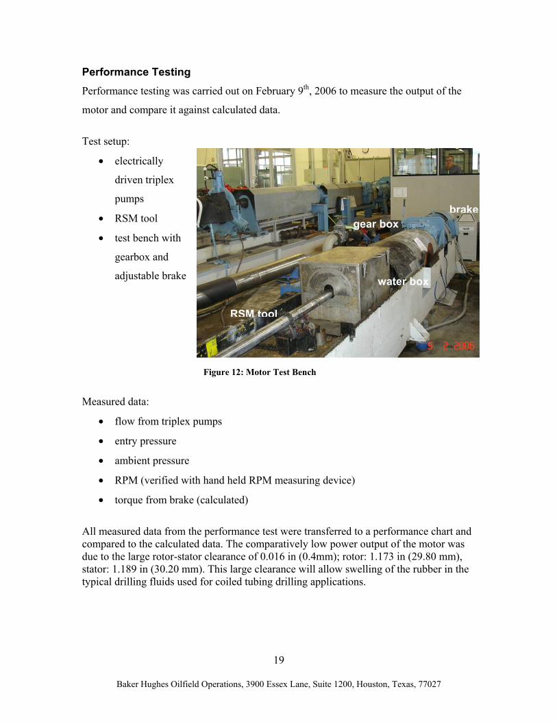
Performance Testing Performance testing was carried out on February 9th, 2006 to measure the output of the
motor and compare it against calculated data.
Test setup:
• electrically
driven triplex
pumps
• RSM tool
• test bench with
gearbox and
adjustable brake
Measured data:
• flow from triplex pumps
• entry pressure
• ambient pressure
• RPM (verified with hand held RPM measuring device)
• torque from brake (calculated)
All measured data from the performance test were transferred to a performance chart and compared to the calculated data. The comparatively low power output of the motor was due to the large rotor-stator clearance of 0.016 in (0.4mm); rotor: 1.173 in (29.80 mm), stator: 1.189 in (30.20 mm). This large clearance will allow swelling of the rubber in the typical drilling fluids used for coiled tubing drilling applications.
brakegear box
water box
RSM tool
Figure 12: Motor Test Bench

20
Baker Hughes Oilfield Operations, 3900 Essex Lane, Suite 1200, Houston, Texas, 77027
High Temperature / High Pressure Testing High temperature / high pressure testing was conducted separately for the electric and hydraulic components, which made an oven test with the complete RSM tool redundant. Summary of Laboratory Test Results
• Maximum BUR: 17.7°/100 feet (10°/100 feet with the bi-center bit)
• Longest run: 10m (32 ft) with build and drop section
• Average parameters: 420 RPM, 66 gpm (250 l/min), 1300 lbs (6 kN) WOB
• Accumulated distance drilled: 100 feet (30 m)
• No visible wear on RSM steering ribs
• The functioning of the different steering modes were verified
• Measured motor performance less than calculated due to large rotor-stator-fit, but
this is needed to allow swelling in drilling mud
21
Baker Hughes Oilfield Operations, 3900 Essex Lane, Suite 1200, Houston, Texas, 77027
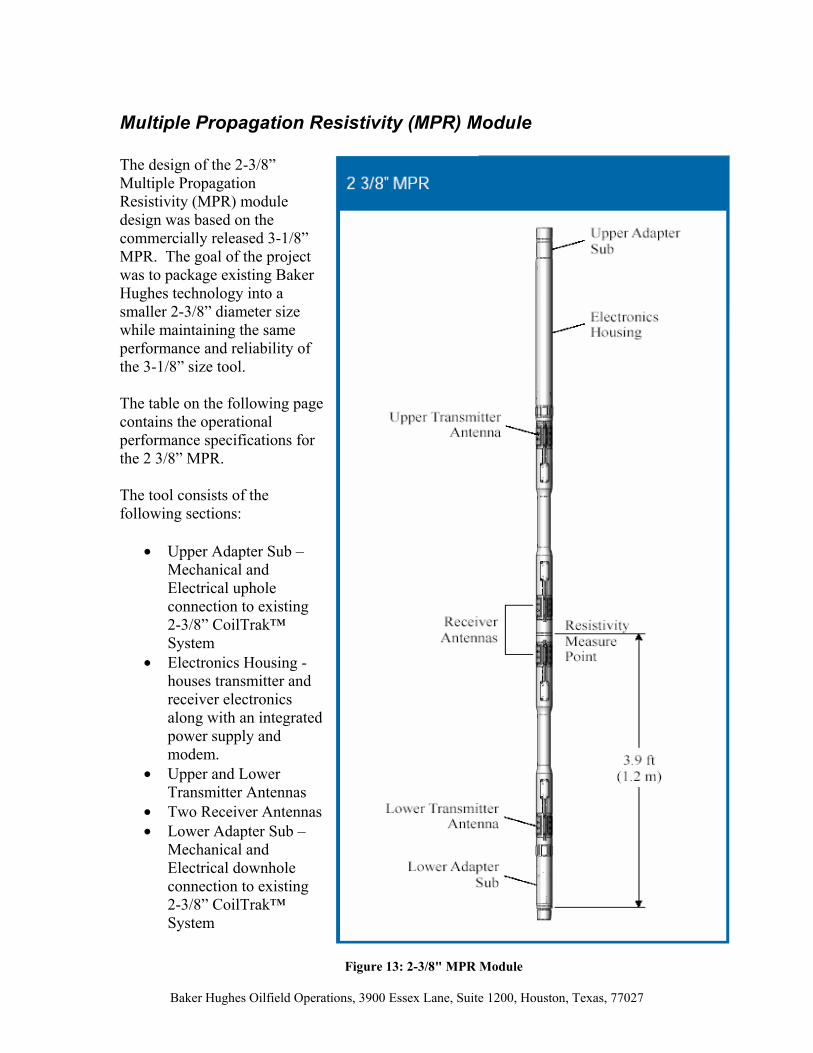
Multiple Propagation Resistivity (MPR) Module The design of the 2-3/8” Multiple Propagation Resistivity (MPR) module design was based on the commercially released 3-1/8” MPR. The goal of the project was to package existing Baker Hughes technology into a smaller 2-3/8” diameter size while maintaining the same performance and reliability of the 3-1/8” size tool. The table on the following page contains the operational performance specifications for the 2 3/8” MPR. The tool consists of the following sections:
• Upper Adapter Sub – Mechanical and Electrical uphole connection to existing 2-3/8” CoilTrak™ System
• Electronics Housing - houses transmitter and receiver electronics along with an integrated power supply and modem.
• Upper and Lower Transmitter Antennas
• Two Receiver Antennas • Lower Adapter Sub –
Mechanical and Electrical downhole connection to existing 2-3/8” CoilTrak™ System
Figure 13: 2-3/8" MPR Module

22
Baker Hughes Oilfield Operations, 3900 Essex Lane, Suite 1200, Houston, Texas, 77027
Figure 14: 2 3/8" MPR Operating Specifications

23
Baker Hughes Oilfield Operations, 3900 Essex Lane, Suite 1200, Houston, Texas, 77027
MPR – Theory of Operation The operation of the 2 3/8” MPR is the same as all the larger size MPR tools developed by Baker Hughes. The two transmitter antennas located outboard emit two constant frequency propagation signals at 2 MHz and 400 kHz. The signal travels through the formation and is detected by the two receiver antennas located inboard. The tool measures the raw signal phase (velocity) and amplitude for each frequency from each transmitter to receiver combination. This is 16 measurements (8 for each frequency). From these measurements, the tool calculates compensated phase difference and attenuation from far to near receiver. Algorithms in the surface system software transform this compensated phase difference and attenuation into a resistivity value. In a high resistivity (less conductive) formation, the signals travel at a higher velocity with less attenuation. Contrary, in a low resistivity (more conductive) formation, the signals travel at a lower velocity with higher attenuation. Generally, the tool is more accurate in low resistivity formations due to a higher phase difference and amplitude ratio. Depth of investigation (DOI) increases with increasing resistivity. The 400 kHz signal propagates further into the formation than the 2 MHz signal. In low resistivity formations, much of the signal is blocked from penetrating deep into the formation. This effect becomes worse with increasing conductivity of the drilling fluid.
Figure 15: MPR Theory of Operation
24
Baker Hughes Oilfield Operations, 3900 Essex Lane, Suite 1200, Houston, Texas, 77027
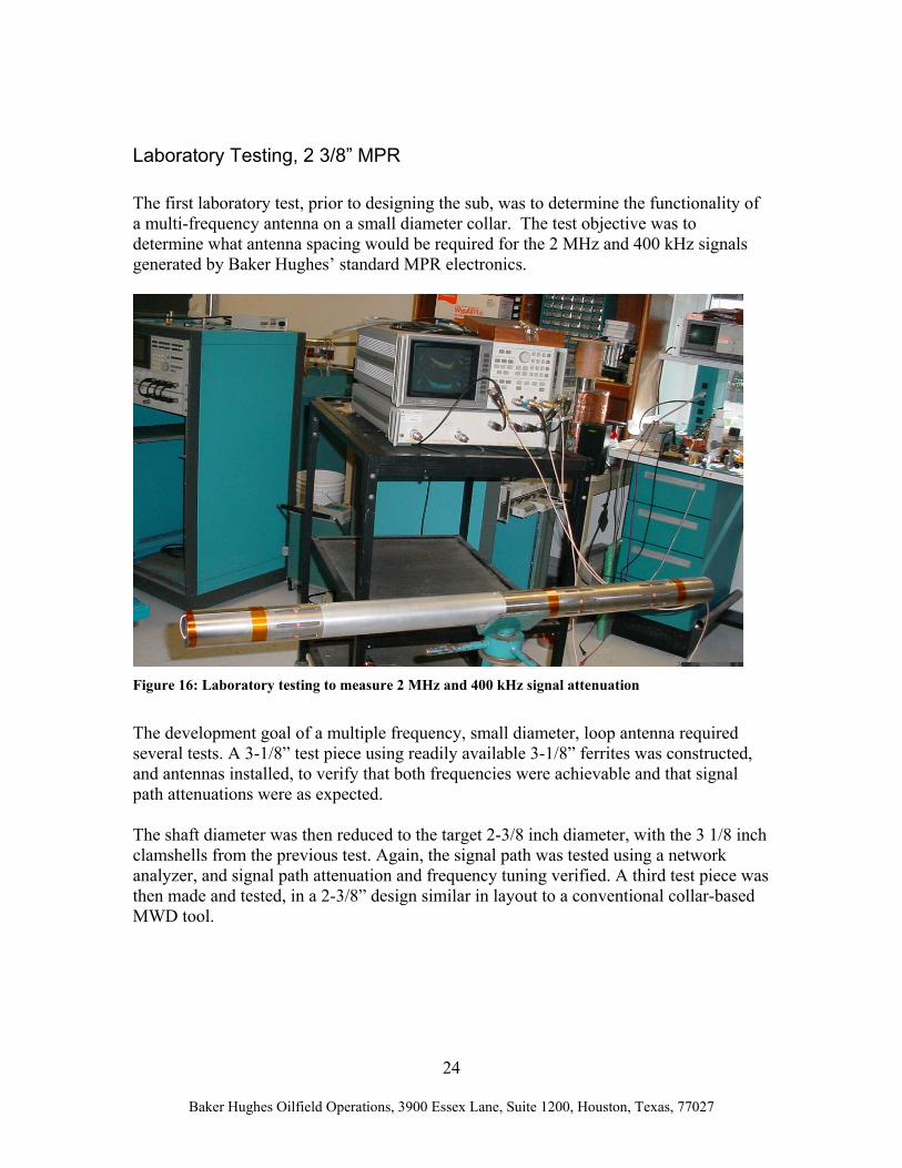
Laboratory Testing, 2 3/8” MPR
The first laboratory test, prior to designing the sub, was to determine the functionality of a multi-frequency antenna on a small diameter collar. The test objective was to determine what antenna spacing would be required for the 2 MHz and 400 kHz signals generated by Baker Hughes’ standard MPR electronics.
Figure 16: Laboratory testing to measure 2 MHz and 400 kHz signal attenuation
The development goal of a multiple frequency, small diameter, loop antenna required several tests. A 3-1/8” test piece using readily available 3-1/8” ferrites was constructed, and antennas installed, to verify that both frequencies were achievable and that signal path attenuations were as expected. The shaft diameter was then reduced to the target 2-3/8 inch diameter, with the 3 1/8 inch clamshells from the previous test. Again, the signal path was tested using a network analyzer, and signal path attenuation and frequency tuning verified. A third test piece was then made and tested, in a 2-3/8” design similar in layout to a conventional collar-based MWD tool.

25
Baker Hughes Oilfield Operations, 3900 Essex Lane, Suite 1200, Houston, Texas, 77027
Figure 17: Laboratory testing, final test piece After the third test, the antennas tuned to the proper frequencies and had the correct signal loss from the transmitter to both the near and far receivers. Next, the antennas were connected to a slim-hole transmitter and receiver board. Distances were varied between the receivers and the transmitter, and the power output of the transmitter was adjusted to determine the optimal distance spacing required between the transmitter and the near receiver to achieve the greatest signal strength.
Figure 18: Laboratory test piece with electronics attached – verification that the frequencies and attenuation were attainable
The results prior to an actual tool build show that two frequencies (2MHz and 400 kHz) were attainable, with the 2 MHz being at 50 ohms and the 400 kHz being at 27 ohms. It

26
Baker Hughes Oilfield Operations, 3900 Essex Lane, Suite 1200, Houston, Texas, 77027
was also shown that the minimum distance between transmitter and near receiver was 27.5 inches, and that the circuits should have sufficient power output levels. The theoretical spacing-modeling showed that a maximum Depth of Investigation (DOI) would be achieved with a spacing of 31 inches, so a compromise spacing of 29” was selected for T1 to R1 (near transmitter-receiver spacing). A spacing of 29” kept the overall length of the tool below the 10-foot maximum design length. Electrical Description, 2-3/8” MPR The MPR electronics consists of two printed circuit board assemblies (PCBA), a transmitter PCBA and a receiver PCBA. Due to space limitations, the power supply and modem, which are usually on a separate PCBA, were integrated into the transmitter PCBA. This integration made it necessary to take extra precautions to minimize noise interference with the receiver communication. Shown below is the actual transmitter PCBA.
Figure 19: Transmitter PCBA, 2-3/8" MPR
The transmitter portion of the PCBA consists of a separate circuit to drive each of the transmitter antennas. These circuits are capable of operating at 2MHz and 400 kHz. The transmitter sequentially receives two numerically controlled and phase locked signals from the receiver PCBA through a coax cable. Along with a command to turn on the transmitter circuits one at a time, this signal is sequentially amplified and sent to the appropriate antenna which emits the signal into the formation. The power supply on the transmitter PCBA supplies the necessary power to the amplifiers and the modem. The modem part of the transmitter PCBA communicates information via the correct protocol. The receiver PCBA, shown below, is electrically connected to the two receiver antennas. The signal received at each antenna is amplified, mixed with transmitting frequency and phase locked to output. This signal is further amplified, and passed through filters to produce clean measurable analog signals. These analog signals are then digitized, passed through a buffer and sent to the Digital Signal Processor (DSP). The DSP compares transmitted and received signals. Since the received signals pass through the formation, they are attenuated in amplitude and phase. The DSP calculates these changes and then stores and sends the information to the surface for further processing into resistivity values.
27
Baker Hughes Oilfield Operations, 3900 Essex Lane, Suite 1200, Houston, Texas, 77027
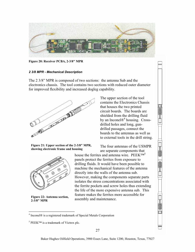
Figure 20: Receiver PCBA, 2-3/8" MPR
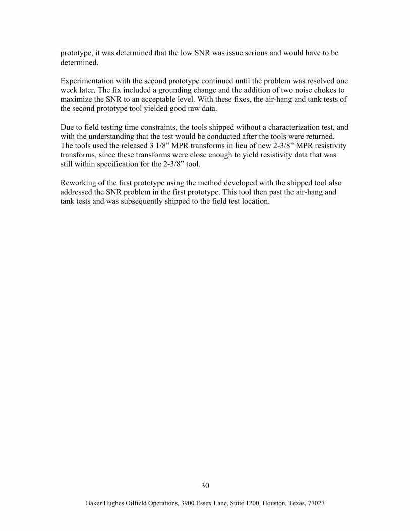
2 3/8 MPR - Mechanical Description The 2 3/8” MPR is composed of two sections: the antenna Sub and the electronics chassis. The tool contains two sections with reduced outer diameter for improved flexibility and increased dogleg capability.
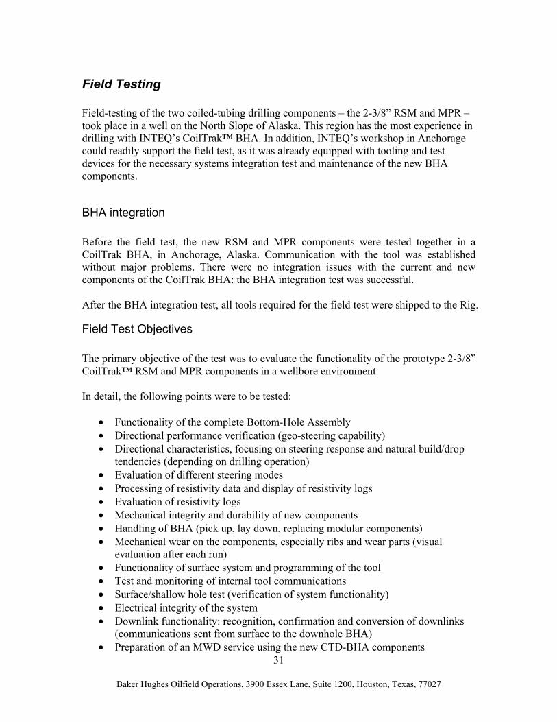
The upper section of the tool contains the Electronics Chassis that houses the two printed circuit boards. The boards are shielded from the drilling fluid by an Inconel®4 housing. Cross-drilled holes and long, gun-drilled passages, connect the boards to the antennas as well as to external tools in the drill string. The four antennas of the USMPR are separate components that
house the ferrites and antenna wire. PEEK™5 panels protect the ferrites from exposure to drilling fluids. It would have been possible to machine the mechanical features of the antenna directly into the walls of the antenna sub. However, making the components separate parts isolates the stress concentrations associated with the ferrite pockets and screw holes thus extending the life of the more expensive antenna sub. This feature makes the ferrites more accessible for assembly and maintenance.
4 Inconel® is a registered trademark of Special Metals Corporation
5 PEEK™ is a trademark of Victrex plc.
Figure 21: Upper section of the 2-3/8" MPR, showing electronic frame and housing
Figure 22: Antenna section, 2-3/8" MPR

28
Baker Hughes Oilfield Operations, 3900 Essex Lane, Suite 1200, Houston, Texas, 77027
To protect against premature wear from contact with the borehole wall, the 2-3/8” MPR has two wear sleeves. These sacrificial parts have laser-clad hard facing to improve wear life and are replaceable. Each antenna on the tool has a machined pocket that contains the corresponding tuning circuit boards. These electronics are easily accessible via a removable hatch cover located adjacent to the related antenna. Internally drilled passages contain the wiring that electrically connects all components. Standard Air and Tank Test Procedure, MPR Tools After completely assembling and temperature testing a resistivity tool, it then proceeds to an air and tank test to measure resistivity values. During the air hang test, the tool is suspended in air in an area that is free of all metallic objects within a 15’ diameter (shown in figure 25). Twenty 60-second samples for compensated phase and attenuation changes are acquired and averaged. These values, called air offset values, are programmed into the receiver PCBA and can be retrieved by the tank test software. The surface software also retrieves these values prior to deploying the tool downhole. A tank test follows the successful completion of the air-hang test. During the tank test, the tool is submerged in a tank filled with salt water of a know resistivity (.2 ohm-meter). Like the air hang test, twenty 60-second samples for compensated phase and attenuation changes are acquired and averaged. The test software then subtracts the appropriate air hang offset values from each reading. The test software uses these adjusted values, along with tool specific transforms generated from characterization testing, to compute resistivity readings. These resistivity readings are compared with the tank resistivity readings to determine if the tool measurements are within specified tolerances.
Figure 24: Wear Sleeve, 2-3/8" MPR
Figure 23: Segment showing hatch cover over tuning circuit boards, 2-3/8” MPR

29
Baker Hughes Oilfield Operations, 3900 Essex Lane, Suite 1200, Houston, Texas, 77027
A resistivity characterization, to measure the performance of the first prototype tool across a range of resistivity, is performed in water from 12 ohm-meter to 0.2 ohm-meter. The measured resistivity curves, along with algorithms generated from modeling, are used to generate resistivity transforms. These final transforms are loaded into and used by lab test and surface software systems to transform compensated phase and attenuation into resistivity readings. Test and Characterization, 2-3/8” MPR During the air hang and tank test of the first prototype tool, there was a potential signal to noise ratio (SNR) problem noted with the assembly, resulting in raw attenuation levels that were lower than expected. The electronics sleeve was removed and all wiring routings checked. After some minor modifications, the tool was reassembled and re-checked, but there was no major improvement seen in the SNR. In the interest of time, it was decided to proceed with a full resistivity characterization of the first tool to determine if the SNR could be tolerated or compensated for by adjusting the resistivity transforms. In parallel, investigations into ways to increase the SNR used the second prototype tool. After analyzing the characterization test data for the first
Figure 25: Air Hang Test Procedure, 2-3/8” MPR
30
Baker Hughes Oilfield Operations, 3900 Essex Lane, Suite 1200, Houston, Texas, 77027
prototype, it was determined that the low SNR was issue serious and would have to be determined. Experimentation with the second prototype continued until the problem was resolved one week later. The fix included a grounding change and the addition of two noise chokes to maximize the SNR to an acceptable level. With these fixes, the air-hang and tank tests of the second prototype tool yielded good raw data. Due to field testing time constraints, the tools shipped without a characterization test, and with the understanding that the test would be conducted after the tools were returned. The tools used the released 3 1/8” MPR transforms in lieu of new 2-3/8” MPR resistivity transforms, since these transforms were close enough to yield resistivity data that was still within specification for the 2-3/8” tool. Reworking of the first prototype using the method developed with the shipped tool also addressed the SNR problem in the first prototype. This tool then past the air-hang and tank tests and was subsequently shipped to the field test location.
31
Baker Hughes Oilfield Operations, 3900 Essex Lane, Suite 1200, Houston, Texas, 77027
Field Testing Field-testing of the two coiled-tubing drilling components – the 2-3/8” RSM and MPR – took place in a well on the North Slope of Alaska. This region has the most experience in drilling with INTEQ’s CoilTrak™ BHA. In addition, INTEQ’s workshop in Anchorage could readily support the field test, as it was already equipped with tooling and test devices for the necessary systems integration test and maintenance of the new BHA components.
BHA integration
Before the field test, the new RSM and MPR components were tested together in a CoilTrak BHA, in Anchorage, Alaska. Communication with the tool was established without major problems. There were no integration issues with the current and new components of the CoilTrak BHA: the BHA integration test was successful. After the BHA integration test, all tools required for the field test were shipped to the Rig.
Field Test Objectives
The primary objective of the test was to evaluate the functionality of the prototype 2-3/8” CoilTrak™ RSM and MPR components in a wellbore environment. In detail, the following points were to be tested:
• Functionality of the complete Bottom-Hole Assembly • Directional performance verification (geo-steering capability) • Directional characteristics, focusing on steering response and natural build/drop
tendencies (depending on drilling operation) • Evaluation of different steering modes • Processing of resistivity data and display of resistivity logs • Evaluation of resistivity logs • Mechanical integrity and durability of new components • Handling of BHA (pick up, lay down, replacing modular components) • Mechanical wear on the components, especially ribs and wear parts (visual
evaluation after each run) • Functionality of surface system and programming of the tool • Test and monitoring of internal tool communications • Surface/shallow hole test (verification of system functionality) • Electrical integrity of the system • Downlink functionality: recognition, confirmation and conversion of downlinks
(communications sent from surface to the downhole BHA) • Preparation of an MWD service using the new CTD-BHA components

32
Baker Hughes Oilfield Operations, 3900 Essex Lane, Suite 1200, Houston, Texas, 77027
Upon arrival at the rig, the complete BHA was connected to the surface system, and testing of real-time data acquisition, and processing, was without a major problem. The next two sections describe the performance of the RSM and MPR components. The well plans in Appendix-A show the planned and delivered well bore.
Field Testing, 2-3/8” RSM
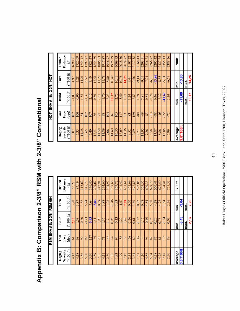
After milling a window at the kick-off point, a short 60-foot section was drilled with a conventional CoilTrak BHA with a Hydraulic Orienting Tool (HOT) and a bent mud motor, so that the RSM could drill from a 3” open hole. The RSM was then picked up to drill the well with minimal dogleg at the required inclination angles. Drilling with the RSM started in inclination hold mode, with no walk force, so the natural walk tendency of the RSM could be determined. With increasing footage, it became more and more obvious that inclination hold mode was operational, and the directional driller did not have to worry about inclination other than to choose a new target inclination when required. In the next step, the walk force was increased slowly until the desired turn rate of 2.6°/100 feet was achieved. Since section length was the primary target of the drilling program, the walk of the well path was chosen to fit into the polygon with the smallest possible constant walk rate. The smaller the average dogleg, the smaller the drag of the coil around the curves of the well: this can be derived from the Euler-Eytelwein formula describing the balance of forces at an arc of contact. The comparison of the RSM run with a later run with a conventional AKO motor (Appendix B) shows that the average dogleg obtained the RSM BHA is smaller than that with of the conventional BHA, and is mainly a function of the walk rate. At the end of the successful 1,300 foot run (run number 8), a mapped fault was crossed 200 foot earlier than anticipated, and resistivity and gamma readings showed that the well had drilled into the overlying shale. The decision was made to plug back 500 foot of this hole and drill an open-hole sidetrack, to dive under the shale. As the first attempt (run number 9) to side track from the open hole was not successful, a liner with an aluminum billet was used (run number 10) to initiate the kick-off in a second attempt (run number 11). Another 680 feet were then drilled (run numbers 12 and 13) with the RSM with low doglegs until the resistivity values indicated proximity to the shale above the wellbore. The target inclination was adjusted to an angle parallel to the formation dip, as the objective was to drill in the upper 5 – 10 feet of the reservoir.

33
Baker Hughes Oilfield Operations, 3900 Essex Lane, Suite 1200, Houston, Texas, 77027
Unfortunately, the first RSM (RSM002) did not drop as expected, and the BHA had to be swapped to a conventional one with a bent motor (run number 14). In surface testing, RSM002 showed full functionality and full extension of all three steering ribs. After the inclination was corrected from 91.5° to 86.9° with a conventional BHA, the second RSM (RSM004) was deployed. Again, the required drop could not be achieved with the RSM and the BHA was pulled after 40 feet of drilling. At surface, RSM004 again showed full functionality and full extension of all three steering ribs. Since modeling indicated that further RSM runs would only add about 50 additional feet to the wellbore length, a conventional hydraulic orienter-based BHA (runs number 16 and 17) drilled the remaining well. Total depth for the well was called early, as the rig had to be moved off the ice pad before the thaw. It was difficult to achieve the required drop in inclination with the conventional hydraulic orienter-based BHA, indicating that the formation had a natural tendency to force the BHA upwards towards the overlying shale. Although the bent motor was oriented to strictly drop (toolface 180°), it only dropped 1°/100 feet and turned 5°/100 feet. The resulting dogleg of 5.1°/100 feet was only half of its normal value. The possible reasons for the failure to drop angle were discussed at a meeting with oil company representatives in Anchorage, on April 12, 2006, and can be summarized:
• Difficult formation: conventional orienter-based BHA also did not drop as expected
• Out of gage hole: effectiveness of the rib-steering device depends on the gage of the borehole – rib effectiveness is decreased in an over-gage hole
• Bi-center bit: not well suited for push-the-bit steering system: too long, low side-cutting capability
• Insufficient Stabilization: 2 ¾” restriction requires undersized stabilizer on Rib Steered Motor:
• Operations: too careful in attempting to change the steering capability of the RSM (adjustment for rib force too low, ROP too high)
The oil company involved in the field tests fully recognized the benefit of the straight well bore produced with the RSM. In order to avoid the difficult formation close to the shale overlying the reservoir it was agreed, in the future, to allow the wellbore to be drilled in the upper 10-15 feet instead of the upper 5-10 feet of the reservoir.
Field Testing, 2-3/8” MPR
Two 2-3/8” MPR tools were field tested during April 2006 in conjunction with the RSM testing, described in the previous section. Overall, the field test was a success. The logging objectives were to help navigate the well for optimum placement, and to evaluate the potential of the field based on quantitative resistivity.
34
Baker Hughes Oilfield Operations, 3900 Essex Lane, Suite 1200, Houston, Texas, 77027
One goal of the drilling program was to drill as far as possible to probe the field periphery, and test the technical limits of small coil drilling. The well was designed to parallel an erosional unconformity and target the uppermost 10 feet of the reservoir. While drilling a nearly horizontal well section, a characteristic separation was observed between the deep and shallow investigation resistivity curves. Such separations typically indicate an approaching boundary. In the high angle well of the field test such separations give, therefore, advance warning of an approaching shale roof. In this area, this particular shale roof always gives rise to borehole stability problems, making drilling difficult. The logged response of the 2-3/8” MPR tool was consistent with the presence of this conductive shale above the reservoir, thus confirming proper operation of the prototype. Based on the information from the 2-3/8” MPR resistivity tool, the well angle was dropped and the well path remained clear of the shale roof. The well stayed within the target zone for approximately 1,000 feet, thus successfully achieving the main objective of the field test. One additional positive aspect of this test was the good agreement observed between modeled results based on computer calculations and actual field data. In the well plans presented in Appendix A of this report, the well path is shown along with the various sidetracks. In the first attempt, the encountered geology – identified from resistivity logs – did not match exactly that predicted by pre-drill models. In particular, the fault came in earlier than projected. As mentioned earlier, resistivity logs guided the final well path and stayed clear of the roof shale. After detailed review of the logs and consideration of the comments made by the oil company geoscientists, it was concluded that both prototypes worked well, except for some erroneous readings by prototype number 1 in the high resistivity zone. Specifically, the 400 kHz attenuation log from resistivity prototype number 1 seemed too low when compared to all other measurements from both tool number 1 and tool number 2. The conditions of the tests were extreme from the resistivity standpoint, since the borehole fluid was a very conductive brine, and the reservoir formation was very resistive. In resistivity logging, very conductive boreholes represent the greatest challenge. It is noted that the first series of logs by this new device gave correct readings in a situation of extreme contrast. The accuracy of the resistivity data provided by these tools for formation evaluation was proven through a “self consistent” approach. In general, the accuracy of new LWD tools is verified by comparing their response with that of a separate wireline run. In this case, the oil company requested no such comparison run. Instead, the geoscientists compared the readings between the various measurements of both prototypes run in succession in the well. The measured logs agreed with the modeled data based on pre-drills, and they determined that both sets of eight curves from each tool were probably accurate, except for the 400 kHz attenuation of prototype number 1 when logging high resistivity. Additionally, differences between “While Drilling” logs and “Measurement after Drilling (MAD)” logs were consistent with the invasion process.

35
Baker Hughes Oilfield Operations, 3900 Essex Lane, Suite 1200, Houston, Texas, 77027
After the completion of the field test, it was determined that prototype number 1 had a noise issue related to the wiring configuration. This is discussed in the 2-3/8” electrical post analysis section of this report. Tool number 1 was subsequently repaired and both tools are ready for additional field-testing.
Drilling Conditions
• Hole size: 3.0 inches • Avg. flow: 58 gpm (220 l/min) • Avg. weight on bit: 3000 lbs (13.3 kN) • Motor RPM: 420 - 450 RPM • Motor work: 400 - 600 psi • Drilled Formations: Claystone / Sandstone • Downhole Temperature: 77°C (170°F) • Mud density: 9.4 ppg (1.13 kg /l) • Avg. ROP: 40 – 70 ft/hr (12 -21 m/hr)
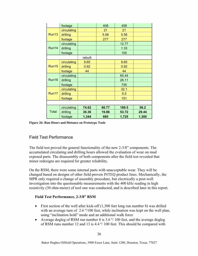
Generally, drilling conditions were quite difficult. The coil and BHA became differentially stuck several times, and had to be worked free. As is customary with CTD operations, the mud had to be kept very clean due to the tight equipment tolerances, and was swapped regularly. After every 50 feet of drilling, wiper trips had to be performed in order to keep the hole clean and avoid the formation of cuttings beds. The coil needed to be kept in motion constantly by the coil operator. The fact that good weight transfer was seen until TD of the well demonstrated the benefit of the straight part of the wellbore that was drilled with the RSM. Run data is summarized for all 4 prototypes (2 x 2-3/8” RSM and 2-3/8” MPR) used during field testing in the next table.
Prototype run hours and footage
Tool 2 3/8” RSM
2 3/8” RSM
2 3/8” MPR
2 3/8” MPR
S/N ZHOT004 ZHOT002 10188653 10190977
circulating 8.77 8.77 drilling 0 0 Run6 footage 0 0 circulating 56.2 56.2 drilling 29.4 29.4 Run8 footage 1,300 1,300 circulating 39.77 39.77 Run12 drilling 14.3 14.3
36
Baker Hughes Oilfield Operations, 3900 Essex Lane, Suite 1200, Houston, Texas, 77027
footage 408 408 circulating 21 21 drilling 5.56 5.56 Run13 footage 277 277 circulating 12.77 drilling 1.33 Run14 footage 100 rebuilt circulating 9.65 9.65 drilling 0.92 0.92 Run15 footage 44 44 circulating 65.44 drilling 26.11 Run16 footage 745 circulating 32.1 drilling 5.5 Run17 footage 151
circulating 74.62 60.77 189.5 56.2 drilling 30.36 19.86 53.72 29.44 Total footage 1,344 685 1,725 1,300
Figure 26: Run Hours and Distance on Prototype Tools
Field Test Performance
The field test proved the general functionality of the new 2-3/8” components. The accumulated circulating and drilling hours allowed the evaluation of wear on mud exposed parts. The disassembly of both components after the field test revealed that minor redesigns are required for greater reliability. On the RSM, there were some internal parts with unacceptable wear. They will be changed based on designs of other field-proven INTEQ product lines. Mechanically, the MPR only required a change of assembly procedure, but electrically a post-well investigation into the questionable measurements with the 400 kHz reading in high resistivity (30 ohm-meter) of tool one was conducted, and is described later in this report.
Field Test Performance, 2-3/8” RSM • First section of the well after kick-off (1,300 feet long run number 8) was drilled
with an average turn of 2.6 º/100 feet, while inclination was kept on the well plan, using “inclination hold” mode and an additional walk force
• Average dogleg of RSM run number 8 is 3.6 º/ 100 feet, and the average dogleg of RSM runs number 12 and 13 is 4.4 º/ 100 feet. This should be compared with
37
Baker Hughes Oilfield Operations, 3900 Essex Lane, Suite 1200, Houston, Texas, 77027
the average dogleg of conventional CoilTrak run number 16, which is 9.8 º/ 100 feet.
• Motor performance was comparable to a conventional 2 3/8” XTreme™ motor • The measured depth achieved with the combination of RSM and conventional
CoilTrak™ BHA was 790 feet longer than that estimated to be possible using only a conventional CoilTrak™ BHA (with 0.8° bent motor and a 12º dogleg). 1,450 feet of the well path was drilled with RSM and 1,040 feet was drilled with a conventional CoilTrak BHA.
• Good weight transfer to bit (2,000lbs) until TD of well (called TD due to time constraints)
• Limited steerability close to shale due to difficult layered formation (possible reasons listed in field testing section, above), but even a conventional BHA could only drop 1º/100 feet instead of the normal 10º/100 feet.
Field Test Performance, 2-3/8” MPR • Good real time resistivity data (although tool not fully characterized) • Both tools show same readings at same depth • Both tools clearly show formation changes • Formation invasion could be determined in “logging run” while pulling out of
hole with 2-3/8” MPR • Most sensitive resistivity value from tool number 1 was not reasonable. The
reason for this found and corrected post well.
Inclusion of the MPR in the 2-3/8” CoilTrak BHA did not cause any difficulties with the field test, since the resistivity data that were received had the exactly same format as those from an existing 3-1/8” MPR that is used commonly within the 3” CoilTrak BHA.
Post Field Test Analysis, 2-3/8” MPR
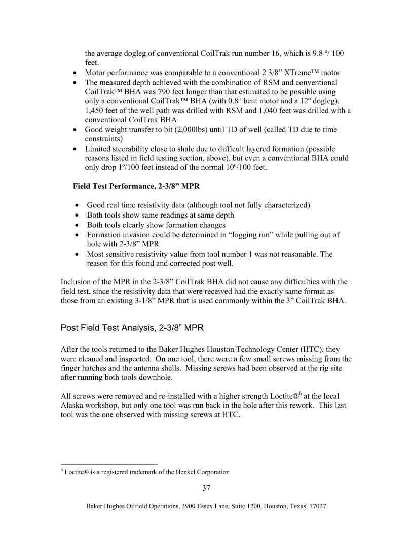
After the tools returned to the Baker Hughes Houston Technology Center (HTC), they were cleaned and inspected. On one tool, there were a few small screws missing from the finger hatches and the antenna shells. Missing screws had been observed at the rig site after running both tools downhole. All screws were removed and re-installed with a higher strength Loctite®6 at the local Alaska workshop, but only one tool was run back in the hole after this rework. This last tool was the one observed with missing screws at HTC.
6 Loctite® is a registered trademark of the Henkel Corporation
38
Baker Hughes Oilfield Operations, 3900 Essex Lane, Suite 1200, Houston, Texas, 77027
Therefore, while the higher strength Loctite® helped, it did not completely fix the loosening screw problem. To address the screw issue, higher strength screws (A286) with higher strength Loctite (262), replaced all antenna and finger hatch screws on both tools, and resulted in a torque increase of ~60%. Outside of this screw issue, the tool held up well mechanically and electrically.
Post Field Test Analysis, 2-3/8” MPR – Electrical One tool (S/N 10190977 – tool number 2) performed well in the field while the other (S/N 10188653 – tool number 1) had questionable measurements with the 400 kHz reading in high resistivity (30 ohm-meter) formations. As verification, both tools were put through post-run air-hang and tank test. The results showed no change from the pre-deployment tests. Since the standard tank test resistivity of 0.2 ohm-meters is much lower than 30 ohm-meters, it was not anticipated that a problem would be detected in the air-hang and tank tests. A supplemental test with gradually decreasing resistivity might have helped detect the problem, but the current equipment can only reach a maximum of 16 ohm-meters. Therefore, before initiating a lengthy test that might or might not help detect the problem, the wiring paths and grounding point were compared between the two tools.
Figure 27: Examples of missing screws, 2-3/8" MPR

39
Baker Hughes Oilfield Operations, 3900 Essex Lane, Suite 1200, Houston, Texas, 77027
In tool number 1, one of the chokes – installed to reduce noise – had been placed on the incorrect power line, and there was a faulty ground. This was corrected, both tools were re-assembled, and the modified tool was re-tested and calibrated. While INTEQ
engineering is confident that this was the source of the problem for the bad 400 kHz reading, it cannot be verified at the Houston facility. With both tools re-assembled, a full resistivity characterization (that was not completed before initial deployment) was performed using tool number 2. The resistivity scientist adjusted the surface transforms to match this characterization data. Figure 29 is a graph of the tank resistivity versus the tools compensated attenuation and phase readings transformed into resistivity measurements. The derived 2-3/8” transforms are very close to the 3-1/8” transforms used during field-testing. Post Field Test Analysis, 2-3/8” MPR – Summary Tool number 2 (S/N 10190977) – good performance downhole
• Clean and Inspected • Replaced all screws w/high strength A286 screws; applied Loctite 262 and
increased torque • Verified calibration – Good
2 3/8" Tank data after correction
0.1
1
10
100
0.1 1 10 100
Tank Resistivity
App
aren
t Res
istiv
ity
Ra2MHz
Rp2MHz
Ra400kHz
Rp400kHz
Figure 28:Evaluation of tool response -- known tank resistivity versus tool measured resistivity
40
Baker Hughes Oilfield Operations, 3900 Essex Lane, Suite 1200, Houston, Texas, 77027
• Used to run full a characterization that was not completed before initial deployment
Tool number 1(S/N 10188653)
• Clean and Inspected • Replaced all screws w/high strength A286 screws; Applied Loctite 262 and
increased torque • Verified calibration – Good (could not detect problem with 400 kHz reading) • Corrected choke placement by moving from -5V Digital line to Analog line
(matches wiring of tool number 1) and fix faulty ground. • Re-test and re-calibrate
Both tools are awaiting deployment to the next available opportunity. Conclusions Field-testing of the two new 2-3/8” coiled tubing drilling BHA components, RSM and MPR, was an overall technical success, showing that both components add benefit when drilling re-entry wells. The investment of the DOE was a substantial contribution to the development of new techniques to recover oil and gas for the American market. In two long runs, it was shown that the 2 3/8” RSM is able to produce a significantly smoother borehole than a conventional BHA with a bent motor. Demonstrated good weight transfer 790 feet beyond the calculated point of conventional coil lock-up illustrates the benefit of this “gun-barrel” type borehole. The 2 3/8” MPR added valuable information about the placement of the well within the pay zone. The oil company wellsite geologist indicated that the while-drilling resistivity response was critical to drilling of the well, and after-drilling resistivity measurements were ideal for evaluating POWC, tight streaks, water influx along faults and close approach to the overlying shale. The mechanical design of the tool was good, as demonstrated by handling of the BHA on the catwalk and the rig floor. Picking up the 2-3/8” RSM involved procedural changes, and the tool connections proved to be reliable while making up the BHA in two pieces. There were no problems preparing the BHA for a run. The integration of the new components in the existing CoilTrak BHA caused no additional effort. The downlink capabilities and the bi-directional communication were solid throughout the test. All commands sent from surface were received downhole and executed. From the directional drilling point of view, the inability to drop angle in the field test resulted in some discussion on the best way to address this observed shortcoming:

41
Baker Hughes Oilfield Operations, 3900 Essex Lane, Suite 1200, Houston, Texas, 77027
• Design of a special “steerable” 3 inch bi-center bit, with increased side-cutting
ability • Influence of the undersized stabilizer, which is required to fit through the 2-¾”
restriction • Influence of greater rib forces on achievable build/drop rate • Influence lower ROP on achievable build/drop rate
The field test was not quite complete, as the maximum dogleg capability with the 2-3/8” RSM could not be determined due to time constraints; the test plan did include dropping with maximum angle at the end of the well to determine the oil-water contact. It would also have been useful to find out the total achievable drilling distance with the 2-3/8” RSM tool in the hole. Mechanical durability of the 2-3/8” RSM was investigated after the tools were shipped back from the field test location, and parts showing unacceptable wear will be redesigned in the near future for higher reliability. For the 2-3/8” MPR this was a successful first field test, with the tool delivering usable measurements and the operator using the device for geosteering, and avoiding a post-drilling wireline log run. Minor tool-assembly procedural problems have been addressed, and a wiring issue in one of the prototypes has been identified and corrected. The rapid development of these tools, from concept through successful field-testing, is certainly an indication of the skill of the engineering teams involved. Baker Hughes INTEQ would like to thank the U.S. Department of Energy for partially funding the development of these two prototypes for microhole drilling. Without their involvement, it is unlikely that these tools would have been developed in a timely fashion. Baker Hughes INTEQ will re-run these tools in the near future on further tests, to both further verify their performance and to accumulate operating hours. In 2007 it will then make a decision on design changes, if any, and decide on a further build to support commercial microhole operations.

42
Bak
er H
ughe
s Oilf
ield
Ope
ratio
ns, 3
900
Esse
x La
ne, S
uite
120
0, H
oust
on, T
exas
, 770
27
App
endi
x A
: Fie
ld T
est W
ell S
ectio
ns
Pla
n V
iew
-120
0-1
100
-100
0-9
00-8
00-7
00-6
00-5
00-4
00-3
00-2
00-1
00010
020
030
040
050
060
070
080
090
010
00
9800
9900
10000
10100
10200
10300
10400
10500
10600
10700
10800
10900
11000
11100
11200
11300
11400
11500
11600
11700
11800
11900
12000
mot
her w
ell
wel
l pla
n #
10w
ell A
wel
l A p
lugb
ack
Pol
ygon
Faul
t1
East
(+) /
Wes
t (-)
North (+) / South (-)
Targ
et 2
Targ
et 3
Kic
k-of
fSide
trac
k fro
m b
illet
Run
8: R
SM
plug
bac
k
Run
12
&13
: RSM
proj
ecte
d fa
ult
0500
1000
1500
050
010
0015
00

43
B
aker
Hug
hes O
ilfie
ld O
pera
tions
, 390
0 Es
sex
Lane
, Sui
te 1
200,
Hou
ston
, Tex
as, 7
7027
Se
cti
on
Vie
w
8800
8900
9000
9100
9200
9600
9700
9800
9900
10000
10100
10200
10300
10400
10500
10600
10700
10800
10900
11000
11100
11200
11300
11400
11500
11600
11700
11800
11900
12000
mot
her w
ell
wel
l pla
n #
10w
ell A
wel
l A p
lugb
ack
Vertical Depth from K-O point
proj
ecte
d fa
ult
actu
al fa
ult
Run
8: R
SM
Run
12
& 1
3: R
SM
side
trac
k
050
010
0015
0020
00
0 -100
-200
44
B
aker
Hug
hes O
ilfie
ld O
pera
tions
, 390
0 Es
sex
Lane
, Sui
te 1
200,
Hou
ston
, Tex
as, 7
7027
App
endi
x B
: Com
paris
on 2
-3/8
” R
SM w
ith 2
-3/8
” C
onve
ntio
nal
Dog
leg
Too
lB
uild
Tur
nD
rille
dD
ogle
gT
ool
Bui
ldT
urn
Dri
lled
Seve
rity
Face
Dist
ance
Seve
rity
Face
Dis
tanc
e(°
/100
ft)
(deg
)(°
/100
ft)
(°/1
00 ft
)(f
t)(°
/100
ft)
(deg
)(°
/100
ft)
(°/1
00 ft
)(f
t)4,
4361
2,13
3,90
53,2
25,
0710
2-1
,03
4,97
1690
,81
4,18
681,
583,
8784
,19
5,35
100
-0,9
05,
2817
25,0
93,
8699
-0,6
03,
8211
5,62
14,2
884
1,55
14,2
117
54,7
25,
8099
-0,9
35,
7414
5,77
6,65
102
-1,3
76,
5217
92,7
75,
76-1
27-3
,43
-4,6
417
6,40
7,40
107
-2,1
27,
1018
23,4
73,
89-6
91,
41-3
,64
209,
6712
,51
860,
8012
,51
1854
,89
2,05
201,
930,
6924
2,91
11,5
877
2,61
11,2
918
85,5
34,
1171
1,36
3,88
274,
6011
,89
98-1
,70
11,7
819
17,8
72,
3014
6-1
,91
1,28
304,
979,
0610
4-2
,23
8,80
1946
,97
1,05
-26
0,95
-0,4
633
7,68
14,6
046
10,1
710
,49
1975
,39
1,93
94-0
,13
1,93
367,
7210
,50
105
-2,7
510
,13
2009
,93
1,99
-52
1,22
-1,5
740
1,42
12,0
911
7-5
,50
10,7
820
38,5
07,
4279
1,42
7,29
431,
6114
,36
831,
8714
,25
2074
,92
2,31
168
-2,2
60,
5046
1,69
9,52
831,
249,
4421
07,2
23,
6480
0,61
3,60
492,
832,
8916
9-2
,83
0,56
2137
,58
1,51
147
-1,2
70,
8252
2,05
9,27
-80
1,59
-9,1
421
68,4
31,
164
1,16
0,08
569,
5511
,95
-49
7,81
-9,0
522
03,9
14,
8696
-0,4
94,
8460
0,35
7,26
-83
0,84
-7,2
122
36,2
35,
3482
0,75
5,30
629,
796,
58-1
14-2
,70
-6,0
022
66,9
24,
2887
0,20
4,28
660,
4113
,87
-88
0,46
-13,
8622
95,4
24,
7881
0,75
4,72
692,
598,
86-1
05-2
,32
-8,5
523
27,2
52,
1813
5-1
,54
1,54
724,
4112
,85
-155
-11,
69-5
,34
2355
,13
2,76
890,
032,
7675
5,52
6,99
-72
2,14
-6,6
723
88,2
6
Aver
age
min
.m
in.
700f
tAv
erag
em
in.
min
.70
0ft
3.6°
/100
ft-3
,43
-3,6
49.
8°/1
00ft
-11,
69-1
3,86
max
.m
ax.
max
.m
ax.
2,13
7,29
10,1
714
,25
HO
T B
HA
# 16
: 2
3/8"
HO
TR
SM B
HA
# 8:
2 3
/8"
RSM
004