
Microfluidics in Surface Modified PDMS - DiVA portal169223/FULLTEXT01.pdf · Abbreviations ACN...
54
ACTA UNIVERSITATIS UPSALIENSIS UPPSALA 2006 Digital Comprehensive Summaries of Uppsala Dissertations from the Faculty of Science and Technology 241 Microfluidics in Surface Modified PDMS Towards Miniaturized Diagnostic Tools SARA THORSLUND ISSN 1651-6214 ISBN 91-554-6716-4 urn:nbn:se:uu:diva-7270
-
Upload
phungquynh -
Category
Documents
-
view
221 -
download
0
Transcript of Microfluidics in Surface Modified PDMS - DiVA portal169223/FULLTEXT01.pdf · Abbreviations ACN...

ACTAUNIVERSITATISUPSALIENSISUPPSALA2006
Digital Comprehensive Summaries of Uppsala Dissertationsfrom the Faculty of Science and Technology 241
Microfluidics in Surface ModifiedPDMS
Towards Miniaturized Diagnostic Tools
SARA THORSLUND
ISSN 1651-6214ISBN 91-554-6716-4urn:nbn:se:uu:diva-7270


Published by kind permission of PIB Copenhagen/www.pib.dk


Papers included in the thesis
This thesis is based on the following papers, which are referred to in the text by their Roman numerals:
I A hybrid poly(dimethylsiloxane) microsystem for on-chip whole blood filtration optimized for steroid screeningSara Thorslund, Oliver Klett, Fredrik Nikolajeff, Karin Markides and Jonas Bergquist, Biomed Microdevices, 8, 73-79 (2006)
II Functionality and stability of heparin immobilized onto poly(dimethylsiloxane) Sara Thorslund, Javier Sanchez, Rolf Larsson, Fredrik Nikolajeff and Jonas Bergquist, Colloids and Surfaces B: Biointerfaces, 45, 76-81 (2005)
III Bioactive heparin immobilized onto microfluidic channels in poly(dimethylsiloxane) results in hydrophilic surface proper-tiesSara Thorslund, Javier Sanchez, Rolf Larsson, Fredrik Nikolajeff and Jonas Bergquist, Colloids and Surfaces B: Biointerfaces, 46, 106-113 (2005)
IV Modified bioactive PDMS microchannel evaluated as sensor for human CD4+ cells - the concept of a point-of-care method for HIV monitoringSara Thorslund, Rolf Larsson, Fredrik Nikolajeff, Jonas Bergquist and Javier Sanchez, Accepted for publication in Sen-sors and Actuators B: Chemical
V A PDMS-based Disposable Microfluidic Sensor for CD4+
Lymphocyte Counting Sara Thorslund, Rolf Larsson, Jonas Bergquist, Fredrik Nikola-jeff and Javier Sanchez, Manuscript
VI A simplified method for capillary embedment into micro-fluidic devices exemplified by sol-gel based preconcentration Sara Thorslund, Nina Johannesson, Fredrik Nikolajeff and Jonas Bergquist, In progress Analytical Chemistry

VII Sample pretreatment on a microchip with an integrated electrospray emitter Peter Lindberg, Andreas P. Dahlin, Sara K. Bergström, Sara Thorslund, Per E. Andrén, Fredrik Nikolajeff and Jonas Bergquist, Electrophoresis, 27, 2075-2082 (2006)
VIII Electrokinetic-driven microfluidic system in poly(dimethylsiloxane) for mass spectrometry detection integrating sample injection, capillary electrophoresis, and electrospray emitter on-chipSara Thorslund, Peter Lindberg, Per E. Andrén, Fredrik Nikola-jeff and Jonas Bergquist, Electrophoresis, 26, 4674-4683 (2005)
IX Instant oxidation of closed microchannelsSara Thorslund and Fredrik Nikolajeff, In Progress Journal of Micromechanics and Microengineering
Reprints were made with kind permission from the publishers.
Contents
Introduction to Miniaturized Analytical Systems composed of Polymeric Materials .......................................................................................................11
The Fundamental Idea of a Lab-on-Chip......................................................13...As a Time and Money Saver in the Lab................................................13...As a Point-of-Care Testing Device .......................................................13
Poly(dimethylsiloxane) (PDMS) ..................................................................15Material Properties ...................................................................................15Rapid Prototyping of PDMS ....................................................................16Pros and Cons of PDMS...........................................................................18
The Need for Surface Modifications.............................................................19Blood-Materials Interactions....................................................................19Heparin Immobilization ...........................................................................21
Characterization and Detection Principles ....................................................23Electrospray Ionization Mass Spectrometry (ESI-MS)............................23Quartz Crystal Microbalance-Dissipation ................................................25Electroosmotic Flow Measurements ........................................................26
Summary of the Contents of the Included Papers.........................................29Overall Aims ............................................................................................29Sample Preparation ..................................................................................31
Blood Filtration (paper I).....................................................................31Desalting and Pre-concentration (papers VI and VII) .........................31
Surface Modification................................................................................33In-channel Oxidation (papers VIII and IX) .........................................33Heparin (papers II and III) ...................................................................34Heparin utilized for CD4-Count (papers IV and V) ............................36
Sample Injection and Detection ...............................................................38Sample Injection and Fluid Flow (paper VIII) ....................................38ESI-MS Detection (papers VII and VIII) ............................................38
Concluding Remarks and Outlook................................................................41
Personal Reflections......................................................................................43

Summary in Swedish ....................................................................................45
Acknowledgements.......................................................................................47
References.....................................................................................................49

Abbreviations
ACN acetonitrile AT antithrombin BSA bovine serum albumin CAD computer-aided design CE capillary electrophoresis COC cycloolefin copolymer DNA deoxyribonucleic acid EDTA ethylenediaminetetraacetic acid EOF electroosmotic flow ESI electrospray ionization ICO in-channel oxidation LOD limit of detection MEMS micro electromechanical system MS mass spectrometry PAV proprietory polymeric amine
(Corline, Sweden) PC polycarbonate PDMS poly(dimethylsiloxane) PMMA polymethylmetacrylate POC point-of-care PP polypropylene QCM-D quartz crystal microbalance-
dissipationRBC red blood cells RSD relative standard deviation RTV room temperature vulcanizing µEO electroosmotic mobility µEP electrophoretic mobility µTAS micro total analysis system WBC white blood cells

11
Introduction to Miniaturized Analytical Systems composed of Polymeric Materials
From the first time in 1990 when the idea of micro total analysis systems(µTAS) was introduced1, the development and number of research groups working within the area has increased enormously. The initial thought was that µTAS would gain better performances within chromatographic and elec-trophoretic separations, be faster and have higher selectivity and consume less expensive reagents compared to existing systems2. This has to some extent been true and fabrication technologies, various materials and micro-chip modules have successfully been explored during the years3-7.
An additional reason for the fast development of microfluidic systems was the threat of chemical and biological weapons during the 90’s. Aca-demic research in many countries was financially supported to develop port-able microsystems that could serve as detectors for chemical and biological hazardous compounds8. The subject is still highly relevant and is probably both a direct, but also subconscious, aim in many research projects.
In rough outline, the trends in microfluidic systems seem to have gone from being of more analytical chemical interest, to include proteomic and genomic assays, and by today being of highest interest within all sorts of cell handling and analysis9-12. A recent review on cells on chip emphasizes appli-cations like cell responses to biochemical and mechanical changes, cell sort-ing, analysis of cell lysates and biosensors that monitor physical changes in reporter cells13.
In the beginning of the microfluidic device era, the materials of choice were mainly silicon or glass. This was due to the fact that the microfabrication methods were well established within the semiconductor and MEMS (micro electromechanical system) industry, where silicon has been the successful material to use. Glass was well characterized within chromatography and was also an attractive material from a microfabrication point of view. How-ever, due to high production costs and disadvantageous properties (e.g. lack of optical transparency with silicon and no gas permeability), most of the devices are today fabricated in polymer-based substrates8, 14.
The choice of polymer, or plastic if additives are added to the polymer base, depends of course on the desired fabrication parameters, but optical properties, adsorptiveness, thermal stability, surface charge, heat dissipation
12
et cetera are also important for microfluidic devices. When replicating mi-crofluidic structures by injection molding or hot embossing methods, PMMA (polymethylmetacrylate), PC (polycarbonate) and COC (cycloolefin copolymer) are the standard thermoplastic materials of choice. These materi-als are rigid at room temperature and need to be heated to fairly high tem-peratures (about 150 ºC for embossing and at least 200 ºC for injection mold-ing) at time of replication15. Furthermore the tool costs are high, which make these methods difficult to access in academic research.
Much of the non-commercial research on microfluidics has hence been carried out using a more low-cost method, namely casting of the silicon-based elastomer PDMS (poly(dimethylsiloxane)). The viscous polymer is casted on a structured mold; upon curing the polymeric substrate is removed and has the negative image of the structure imprinted. Cured PDMS is a soft elastomer at room temperature and is for that reason particularly useful in pump or valve constructions on-chip16, 17. The material has also other proper-ties like optical transparency, gas permeability and high inertness, that make it suitable for numerous microfluidic applications18. All microdevices evalu-ated in this work are fabricated in PDMS elastomer.
Miniaturized microfluidic systems, µTAS or so called lab-on-chip systems, were and are predicted as future solutions within countless biomolecular, chemical analytical and system biology areas19-21. The progress has not been as fast as initially expected and above all has the introduction of robust lab-on-chip systems on the market been slow22. The academic research often deals with proof-of-concept demonstrations and naturally this must be ex-plored, but to reach commercial exploitation the systems need to be further adapted to users that are non-experts in microfluidics8. The microdevices should be helping tools and simplify the work for persons who are experts in other areas (usually with limited knowledge in microfluidics): e.g. physi-cians, police officers, environmental surveyors, cell biologists, pharmaceuti-cal developers. So called point-of-care lab-on-chip systems for medical di-agnostics need a substantial high degree of user adaptation, which is extra obvious when the systems are intended for the developing world.
13
The Fundamental Idea of a Lab-on-Chip
...As a Time and Money Saver in the Lab A disproportional large part of the analysis time in standard laboratories is devoted to sample preparation (cell lysing, centrifugation, pre-concentration, dilution), pipetting small volumes of reagents repeatedly and things like putting bottle caps on and off. If automated lab-on-chip systems could per-form all these tasks, time and with that money could be saved for many rou-tine analyses. To this adds the possibility to reach higher reproducibility and less reagent consumption.
Time can also be saved from the miniaturization in itself, since many re-actions (capillary electrophoresis or polymerase chain reactions for example) are faster and more accurate in systems with smaller sample volumes and better heat transfer. Other reactions are simply not possible in large-scale due to massive heat production during the reaction23.
A large benefit of using microfluidics is the high-throughput possibility24.Hundred of samples can be run simultaneously or a single sample can be screened against numerous targets at the same time. This makes the lab-on-chip idea highly interesting for applications like drug screening, DNA se-quencing, protein analysis and cell-based assays.
...As a Point-of-Care Testing Device As the name implies, a point-of-care (POC) device for medical diagnostics should be able to fulfill its task as close to the patient as possible, i.e. in the ambulance, at the police station, at the sports arena, in the doctor’s office or sometimes preferably by the patient herself at home depending on the appli-cation of the test. The appealing idea with POC devices is that the user should only have to load the sample, e.g. blood, urine or saliva, onto the chip. The rest should automatically be handled by the equipment and the test result will in the end be presented to the user in an easy understandable form. The sensitivity, specificity and reproducibility of the test should in prefer-ence be close to the corresponding laboratory test.

14
Disposable immunochromatographic strips that can be handled by the patient herself have become available during the last decade. The strips include tests for pregnancy25, diphtheria toxin26, some sexually transmitted diseases27,drugs-of-abuse intake28 et cetera. However, some of these tests suffer from low sensitivity and selectivity and do often only give a qualitative answer. Lab-on-chip devices for POC must perform better than this and rather give quantitative results, especially where the analyte level is important.
The approach of using disposable chips together with a stationary reader is predicted as the winning concept for microfluidic POC tests. The risk of carry-over is minimized and the cost per test could still be low. Successful examples of this kind of POC are the mobile glucose tests available on the market29. A few µL of blood is drawn into a single-use device, which is placed in a small reader. Reliable results are then presented within minutes.
Microfluidic POC tests need to fulfill certain criteria in order to compete with present technology. Apart from having high accuracy and being of low cost, a test must include few manual steps, give a rapid test result and be stable over time. If the tests are intended for the developing world, the crite-ria are extended with factors like low power consumption due to instable power sources, and stability of both the test and the samples in environments with large temperature and humidity differences30.
Figure 1. Uppsala has two companies working with lab-on-chip applications. a) Gyros is developing high-throughput microfluidic devices - here their Bioaffy® CD for protein quantification31. b) Åmic develops lab-on-chip systems for POC diagnostics. The photo shows their 4cast-chip that utilizes micro pillar driven flow for detection of cTroponin I32.
15
Poly(dimethylsiloxane) (PDMS)
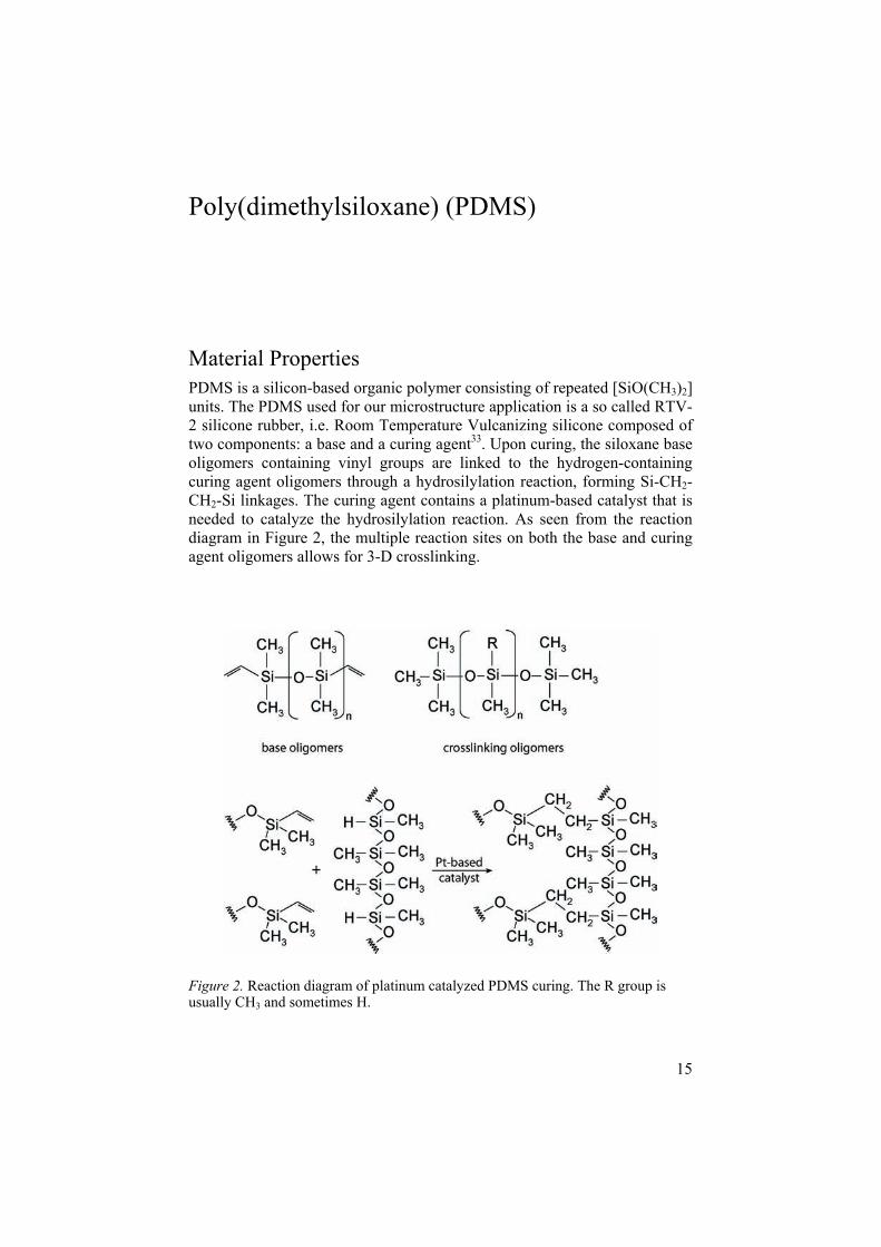
Material Properties PDMS is a silicon-based organic polymer consisting of repeated [SiO(CH3)2]units. The PDMS used for our microstructure application is a so called RTV-2 silicone rubber, i.e. Room Temperature Vulcanizing silicone composed of two components: a base and a curing agent33. Upon curing, the siloxane base oligomers containing vinyl groups are linked to the hydrogen-containing curing agent oligomers through a hydrosilylation reaction, forming Si-CH2-CH2-Si linkages. The curing agent contains a platinum-based catalyst that is needed to catalyze the hydrosilylation reaction. As seen from the reaction diagram in Figure 2, the multiple reaction sites on both the base and curing agent oligomers allows for 3-D crosslinking.
Figure 2. Reaction diagram of platinum catalyzed PDMS curing. The R group is usually CH3 and sometimes H.
16
The addition process produces no cure by-products, such as water. This results in no weight loss of PDMS on curing and very low shrinkage (< 0.1 %), which is advantageous in microstructure casting. Heating the polymer mixture additionally accelerates the curing.
Process parameters The PDMS used in all our studies was from Wacker, denoted Elastosil RT 601. The material properties of this PDMS differ somewhat from the more commonly used Sylgard 184 from Dow Corning34, 35, with the most pre-dominant difference being a larger curing acceleration upon heat supply. We performed all PDMS curing (thickness 1 cm) at 70 °C for 30-60 min.
The base and curing agent were mixed in weight ratio 10:1 and further degassed by placing the polymer mixture in -20 °C for 1 h. Bubbles formed after pouring the uncured PDMS on its master usually rose to the surface and diminished; during this process step the PDMS/masters were stored at + 6 °C to counteract curing. Bubbles which were not broken when reaching the surface were removed by blowing nitrogen gas across the surface.
Rapid Prototyping of PDMS The PDMS devices were all fabricated using the well-known rapid prototyp-ing method36-39, meaning that an initial master is fabricated from which PDMS replicas are casted repeatedly. The masters were fabricated using clean-room facilities, whereas the PDMS casting was performed in semi-clean environment.
The wanted pattern was CAD drawn and printed to a chrome mask. Sili-con wafers were coated with SU-8, an epoxy based negative resist, of de-sired thickness. The chrome pattern was further transferred to the SU-8 by photolithography, followed by different post-baking and developing steps. By repeating the resist coating and photolithographic steps, patterns with more than one height could be fabricated. PDMS casting was made easier by placing the finished master in a metal ring with in-sets for a 4 inch wafer. PDMS was poured over the structured silicon wafer; bubbles were removed as described earlier before curing in oven. The cured PDMS slab was peeled off from the master (Figure 3) and the microstructures were cut into appro-priate size. Any reservoir holes were punched at this point of fabrication.
PDMS has the advantage of sealing to itself as well as to other materials. After exposing two separate PDMS surfaces to oxygen plasma or corona discharge, the surfaces can be brought into contact and an irreversible bond is formed14, 36-38, 40. The oxidation process is believed to form oxygen-rich silanol groups (Si-O-) in the outermost surface region, which condense into covalent Si-O-Si bonds when two surfaces are sandwiched. If the two PDMS surfaces needed careful alignment before bonding (Paper VII and VIII), a

17
droplet of methanol was added between the surfaces to promote smooth movement, which does not degrade the quality of bonding41. A diagram of the complete rapid prototyping process is depicted in Figure 4.
Figure 3. A casted PDMS replica is peeled off from the resist structured master.
Figure 4. Diagram of the Rapid Prototyping process. Masters were fabricated using cleanroom facilities, whereas the PDMS casting was performed in semi-clean envi-ronment.

18
Pros and Cons of PDMS The PDMS material has become popular for microfluidic applications during the last decade because of its numerous advantages over silicon and glass. There are even examples of commercial microfluidic products on the mar-ket42-46*. But as with most things in the world, advantages usually mean at least some disadvantages... The pros and cons of the PDMS material are summarized in Table 136.
Table 1. Properties of PDMS from a microfabrication point of view.
Pros Cons
Inexpensive Hydrophobic, results in poor wettability and high non-specific adsorption (see Figure 5)
Easy and rapid fabrication Not optimal for mass fabrication Covalent bonding with itself and other Si-based materials
Non-rigid (sometimes an advantageous property)
Optically transparent down to 230 nm, adv. for optical characterization Very low fluorescence, adv. for fluorescence measurements Nontoxic, gas permeable and water imper-meable, adv. for cell culturing
Even though the number of advantages seems to outdo the disadvantages of PDMS, the problem with non-specific adsorption of hydrophobic analytes is such a big problem that it sometimes counterbalances all the advantages together. The solution lies in various types of surface modifications40. Sur-face modifications of the PDMS structures has been a large part of this study, including heparin coatings (Paper II and III) and instant oxidation of closed structures (Paper VIII and IX), further discussed in the next chapter.
Figure 5. Example of non-specific adsorption to PDMS. Here is a 50 µm micro-channel flushed with a hydrophobic dye (Rhodamine B) and further rinsed. The fluorescence of the dye spreads far outside the channel dimensions (Paper IX).
*Examples of PDMS-based products are the DynaflowTM microdevice by Cellectricon, valves and pumps by Fluidigm as well as parts of the microfluidic system of the Biacore equipment.

19
The Need for Surface Modifications
Introducing biological samples, such as plasma or whole blood, into micro-systems needs far more consideration on surface modifications compared to working with buffer samples of adjusted pH containing “cells” in form of polymeric beads. Blood-material contact most often initiates surface-mediated reactions that lead to cell activation and blood clotting.
Blood-Materials Interactions The effects of blood-materials interactions are very complex, involving both proteins and cells, and will only be described in brief here.
Inactive plasma proteins become enzymatically active after either direct surface contact or cleavage by other activated proteins. This cascade is the initial phase of blood coagulation, which leads to the formation of thrombin, activated platelets, fibrin and a final clot formation47. The large surface area:volume ratio in microchannels fortifies surface triggered reactions, since a large part of the blood is in contact with the channel walls.
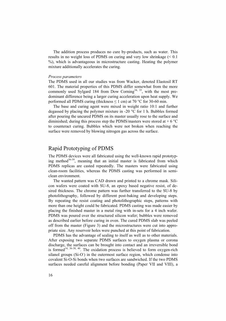
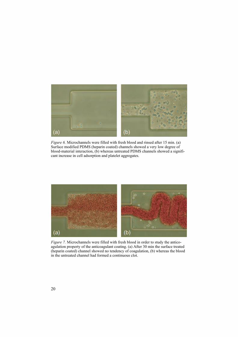
Also blood cells, where platelets, red blood cells (RBC) and white blood cells (WBC) are the large sub-groups of cells, are affected by surface activa-tion48. Platelets are the most sensitive cells, becoming sticky upon surface activation. They bind to the surface and surrounding platelets and also trig-ger the activation of other platelets. RBC are considered more inactive but are trapped in the fibrin net, especially during low laminar flows in micro-channels. The WBC are again more affected by surface interactions, but the many various classes behave very differently49, 50. The effect of a biocom-patible surface modification of microchannels is clearly shown in Figures 6 and 7.
Ca2+ is required for most steps in the coagulation reaction and this is the reason why we added EDTA to the blood when wanting to avoid coagula-tion. EDTA is a chelating agent that strongly binds Ca2+ and is a commonly used anticoagulant factor in blood collection tubes.
20
Figure 6. Microchannels were filled with fresh blood and rinsed after 15 min. (a) Surface modified PDMS (heparin coated) channels showed a very low degree of blood-material interaction, (b) whereas untreated PDMS channels showed a signifi-cant increase in cell adsorption and platelet aggregates.
Figure 7. Microchannels were filled with fresh blood in order to study the antico-agulation property of the anticoagulant coating. (a) After 30 min the surface treated (heparin coated) channel showed no tendency of coagulation, (b) whereas the blood in the untreated channel had formed a continuous clot.
21
Heparin Immobilization Heparin is a naturally occurring polysaccharide, commonly used when creat-ing biocompatible surfaces. Heparin binds to antithrombin (AT) and induces a conformational change of AT, making it more accessible for thrombin binding and thereby inhibiting fibrin formation, i.e. blood clotting51. There are many examples of in vitro studies showing reduced coagulation activa-tion of heparin immobilized surfaces52, 53.
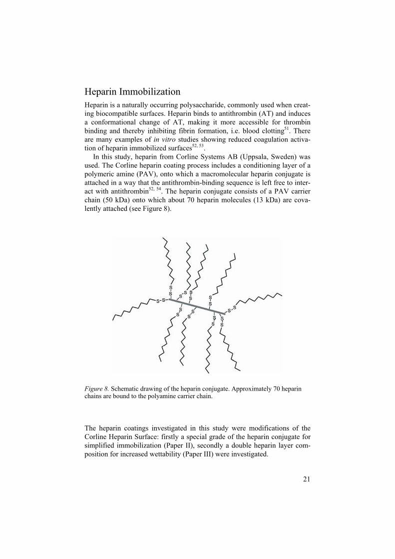
In this study, heparin from Corline Systems AB (Uppsala, Sweden) was used. The Corline heparin coating process includes a conditioning layer of a polymeric amine (PAV), onto which a macromolecular heparin conjugate is attached in a way that the antithrombin-binding sequence is left free to inter-act with antithrombin52, 54. The heparin conjugate consists of a PAV carrier chain (50 kDa) onto which about 70 heparin molecules (13 kDa) are cova-lently attached (see Figure 8).
Figure 8. Schematic drawing of the heparin conjugate. Approximately 70 heparin chains are bound to the polyamine carrier chain.
The heparin coatings investigated in this study were modifications of the Corline Heparin Surface: firstly a special grade of the heparin conjugate for simplified immobilization (Paper II), secondly a double heparin layer com-position for increased wettability (Paper III) were investigated.


23
Characterization and Detection Principles
Various equipments were used throughout the study for detection and char-acterization of the microfluidic devices. Some of them, either extensively used or being of more complex principle are briefly described below.
Electrospray Ionization Mass Spectrometry (ESI-MS) Mass spectrometry (MS) is a sensitive technique that can handle continuous liquid flows and detect analytes present at extremely low concentrations (nM-pM). It has become the major tool for analyzing low abundant bio-molecules since it measures the mass to charge ratio (m/z) of ions and there-fore can identify unknown compounds and additionally identify simultane-ously eluted substances (if not resolved in preceded separation system). In brief, a mass spectrometer first ionizes the sample, then separates the ions of different mass using electric or magnetic fields and further records their rela-tive abundance with a detection system.
Figure 9. The formation of single ions during the ESI process (positive mode). Picture by Andreas Dahlin.

24
The source of ionization utilized in this work is called electrospray ioni-zation (ESI)55. The method provides an excellent interface between systems containing the sample in liquid phase, and the mass spectrometer where the sample is needed in ionized gas phase. In ESI the sample is eluted through e.g. a capillary interfacing the MS inlet. When using ESI in positive mode as in this work, the capillary is held at a higher potential than the MS (several kV potential difference). This forces the sample at the capillary tip to form an elongated cone containing the sample in more positive ionized form. Positively charged droplets are expelled from the tip, the solvent is gradually evaporated and the charged analytes are released as gas phase ions and move towards the MS (see Figure 9)56.
Microfluidic devices are in fact ideal for delivering samples to the MS by ESI. The devices can produce small sample volumes at low flow rates (nL- µL/min), process properties suitable for ESI57. A probable reason for the interest in ESI-microdevices is the knowledge that many processes needed before MS detection (such as sample preparation, separation and desalting) are advantageously performed on-chip; a device comprising these steps as well as having an ESI emitter would provide an integrated solution from sample-introduction to detection.
There are several solutions to produce the electrical contact of the sample outlet facing the MS. The sample liquid can either directly contact a conduc-tive material (sheathless flow) or be assisted by a second flow that contacts the conductive material (sheathflow), utilized in the MS detection of paper VI. The voltage can also be applied upstreams in the flow system. If a sepa-ration step is included on-chip this can waste the preceding sample separa-tion, and the electric contact is better applied as far downstream the micro-fluidic structure as possible, e.g. as a conductive coating onto the capillary or emitter tip (paper VII and VIII). Different coatings for this application were investigated by members of our group, including gold and graphite particles mixed into various polymer bases58-60.
The ESI PDMS devices fabricated in this work were run in sheathless on mass spectrometers without any nebulizing gas or other spray-forming aids. The tip was grounded and the mass spectrometer was put at negative poten-tial to perform positive ESI. The sample on-chip was transferred to the emit-ter tip either by syringe pump infusion (paper VII) or by electroosmotic driven flow (paper VIII).
25
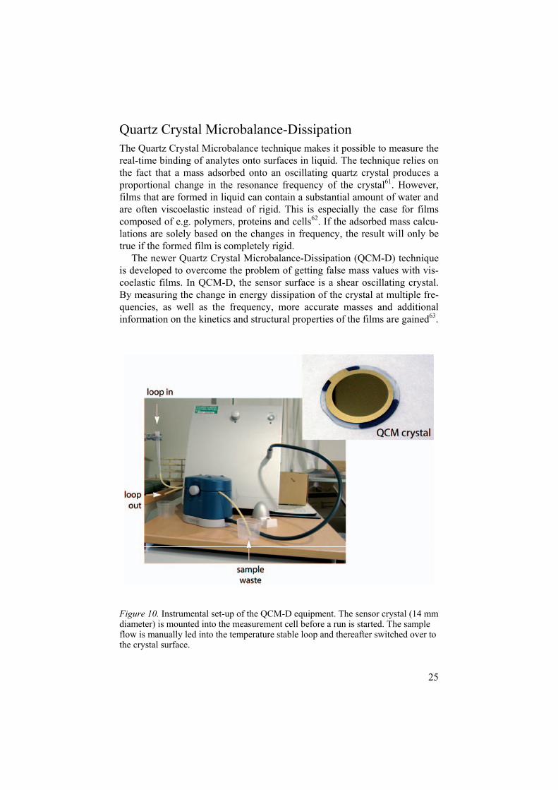
Quartz Crystal Microbalance-Dissipation The Quartz Crystal Microbalance technique makes it possible to measure the real-time binding of analytes onto surfaces in liquid. The technique relies on the fact that a mass adsorbed onto an oscillating quartz crystal produces a proportional change in the resonance frequency of the crystal61. However, films that are formed in liquid can contain a substantial amount of water and are often viscoelastic instead of rigid. This is especially the case for films composed of e.g. polymers, proteins and cells62. If the adsorbed mass calcu-lations are solely based on the changes in frequency, the result will only be true if the formed film is completely rigid.
The newer Quartz Crystal Microbalance-Dissipation (QCM-D) technique is developed to overcome the problem of getting false mass values with vis-coelastic films. In QCM-D, the sensor surface is a shear oscillating crystal. By measuring the change in energy dissipation of the crystal at multiple fre-quencies, as well as the frequency, more accurate masses and additional information on the kinetics and structural properties of the films are gained63.
Figure 10. Instrumental set-up of the QCM-D equipment. The sensor crystal (14 mm diameter) is mounted into the measurement cell before a run is started. The sample flow is manually led into the temperature stable loop and thereafter switched over to the crystal surface.

26
A QCM-D instrument from Q-Sense AB (Göteborg, Sweden) was used (the instrumental set-up is shown in Figure 10). Before a run is started, a quartz crystal is mounted into the measurement cell. During the run, 80 µL sample is maintained over the sensor surface. Before exchanging the solution over the crystal, 0.5 mL sample is temperature stabilized in a temperature-loop, from which the excess volume is allowed to overflow.
In this work, QCM-D was used to study heparin coating of the PDMS material in real-time (paper III). In paper IV, the QCM-D technique was utilized to study the heparin-based sensor surface and its ability to bind CD4-antibodies.
Electroosmotic Flow Measurements A common way to move the solvent in microfluidic systems is to use elec-troosmotic driven flow (EOF). To accomplish EOF, the microchannel wall need to have a net charge in its natural state, become ionized or adsorb ionic species, which makes EOF-driven systems highly pH-dependent. The ability to sustain EOF flow is often a very sought-after property in microfluidic systems, since this creates the opportunity to exclude external syringe pumps or micropump structures on-chip.
If the microchannel walls are negatively charged, as is the case for fused silica capillaries as well as PDMS, positive ions build up at the wall and form a double layer structure. When a voltage is applied across the channel, the ions in the double layer move towards the electrode with lowest poten-tial64. Due to viscous forces, the motion of the double layer is also trans-ferred to the rest of the solvent and creates a bulk flow. The principle of the so called cathodic EOF is drawn in Figure 11. If the channel has openings at both ends, which is most usually the case, the EOF forms a uniform velocity profile across the complete channel. Especially separation applications bene-fit from the flow profile of EOF, since the parabolic flow profile of pump-driven flow more easily results in band broadening. Other pros and cons of using EOF to transport solvents on-chip are listed in Table 2.
Table 2. Pros and cons of using EOF on-chip.
Pros Cons
The uniform velocity profile Requires fairly high voltages (kV) No external syringe pumps or on-chip pump structures are needed
Surface adsorption changes the wall proper-ties and hence the EOF
Easy to re-guide the flow into another chan-nel

27
Figure 11. The ions of the solvent build up a double layer composed of a fixed and a diffuse layer at the microchannel wall. If the channels walls are negatively charged, the double layer will produce a cathodic EOF towards the negative electrode.
Capillary electrophoresis (CE) is a common separation method in channels supporting EOF. Molecules in solvent are differently attracted to electrodes depending on their charge and size. Neutral analytes will have a zero elec-trophoretic mobility, µEP, whereas negatively charged species will move towards the anode and positively charged species towards the cathode. But since the EOF produces a net flow in one direction, an electroosmotic mobil-ity µEO, the overall mobility of a species will be the sum of the µEP and the µEO (see Figure 12)
EOF was evaluated as pumping and sample injection source mainly in paper VIII. The instant oxidation method presented in paper IX was additionally evaluated for its EOF enhancing property.

28
Figure 12. In CE the analytes separate according to their charge and mass. Neutral molecules are only affected by the µEO whereas charged molecules additionally experience a positive or negative µEP.

29
Summary of the Contents of the Included Papers
Overall Aims The general aim of this thesis was to develop and evaluate new microstruc-ture modules that could contribute to the construction of future lab-on-chip systems, especially for point of-care applications. I am myself convinced that the near future commercial systems will be based on fairly simple mi-crostructures with few or none separately fabricated parts; a large part in the success of the systems will lie in functional surface modifications.
Based on these assumptions the more specific aims were: to develop non-complicated microstructure modules, as by means of fabrication, that with as little modification as possible can be integrated into general microfluidic systems.
to integrate several functions into a single microdevice com-posed of one and the same bulk material.
to develop surface modifications for point-of-care micro-devices to enhance their biocompatibility with blood samples.
The various studies included in the thesis deal with several of the parts needed in a complete lab-on-chip system, as outlined in the introduction chapter. The contents of the papers are therefore summarized as parts of the specific chip function, schematically presented in Figure 13.

30
Figure 13. The contents of the included papers divided into microchip functions.
31
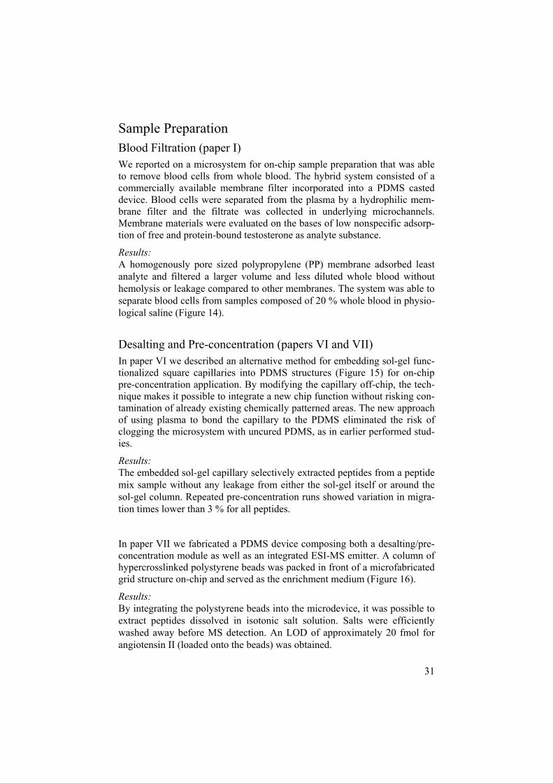
Sample Preparation Blood Filtration (paper I) We reported on a microsystem for on-chip sample preparation that was able to remove blood cells from whole blood. The hybrid system consisted of a commercially available membrane filter incorporated into a PDMS casted device. Blood cells were separated from the plasma by a hydrophilic mem-brane filter and the filtrate was collected in underlying microchannels. Membrane materials were evaluated on the bases of low nonspecific adsorp-tion of free and protein-bound testosterone as analyte substance.
Results:A homogenously pore sized polypropylene (PP) membrane adsorbed least analyte and filtered a larger volume and less diluted whole blood without hemolysis or leakage compared to other membranes. The system was able to separate blood cells from samples composed of 20 % whole blood in physio-logical saline (Figure 14).
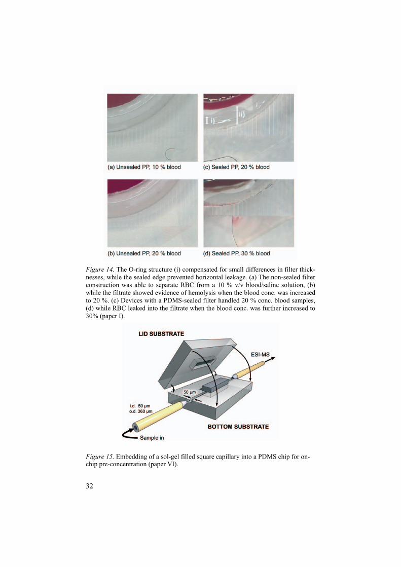
Desalting and Pre-concentration (papers VI and VII) In paper VI we described an alternative method for embedding sol-gel func-tionalized square capillaries into PDMS structures (Figure 15) for on-chip pre-concentration application. By modifying the capillary off-chip, the tech-nique makes it possible to integrate a new chip function without risking con-tamination of already existing chemically patterned areas. The new approach of using plasma to bond the capillary to the PDMS eliminated the risk of clogging the microsystem with uncured PDMS, as in earlier performed stud-ies.
Results:The embedded sol-gel capillary selectively extracted peptides from a peptide mix sample without any leakage from either the sol-gel itself or around the sol-gel column. Repeated pre-concentration runs showed variation in migra-tion times lower than 3 % for all peptides.
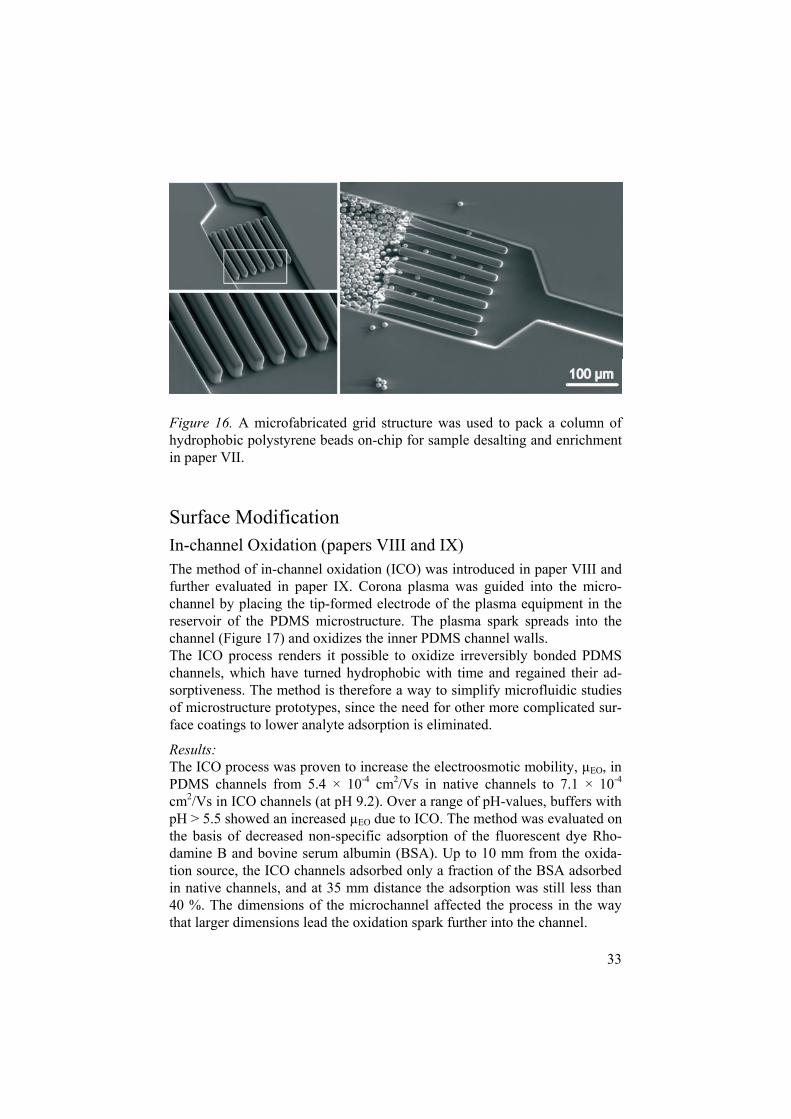
In paper VII we fabricated a PDMS device composing both a desalting/pre-concentration module as well as an integrated ESI-MS emitter. A column of hypercrosslinked polystyrene beads was packed in front of a microfabricated grid structure on-chip and served as the enrichment medium (Figure 16).
Results:By integrating the polystyrene beads into the microdevice, it was possible to extract peptides dissolved in isotonic salt solution. Salts were efficiently washed away before MS detection. An LOD of approximately 20 fmol for angiotensin II (loaded onto the beads) was obtained.
32
Figure 14. The O-ring structure (i) compensated for small differences in filter thick-nesses, while the sealed edge prevented horizontal leakage. (a) The non-sealed filter construction was able to separate RBC from a 10 % v/v blood/saline solution, (b) while the filtrate showed evidence of hemolysis when the blood conc. was increased to 20 %. (c) Devices with a PDMS-sealed filter handled 20 % conc. blood samples, (d) while RBC leaked into the filtrate when the blood conc. was further increased to 30% (paper I).
Figure 15. Embedding of a sol-gel filled square capillary into a PDMS chip for on-chip pre-concentration (paper VI).
33
Figure 16. A microfabricated grid structure was used to pack a column of hydrophobic polystyrene beads on-chip for sample desalting and enrichment in paper VII.
Surface Modification In-channel Oxidation (papers VIII and IX) The method of in-channel oxidation (ICO) was introduced in paper VIII and further evaluated in paper IX. Corona plasma was guided into the micro-channel by placing the tip-formed electrode of the plasma equipment in the reservoir of the PDMS microstructure. The plasma spark spreads into the channel (Figure 17) and oxidizes the inner PDMS channel walls. The ICO process renders it possible to oxidize irreversibly bonded PDMS channels, which have turned hydrophobic with time and regained their ad-sorptiveness. The method is therefore a way to simplify microfluidic studies of microstructure prototypes, since the need for other more complicated sur-face coatings to lower analyte adsorption is eliminated.
Results:The ICO process was proven to increase the electroosmotic mobility, µEO, in PDMS channels from 5.4 × 10⁻⁴ cm2/Vs in native channels to 7.1 × 10⁻⁴
cm2/Vs in ICO channels (at pH 9.2). Over a range of pH-values, buffers with pH > 5.5 showed an increased µEO due to ICO. The method was evaluated on the basis of decreased non-specific adsorption of the fluorescent dye Rho-damine B and bovine serum albumin (BSA). Up to 10 mm from the oxida-tion source, the ICO channels adsorbed only a fraction of the BSA adsorbed in native channels, and at 35 mm distance the adsorption was still less than 40 %. The dimensions of the microchannel affected the process in the way that larger dimensions lead the oxidation spark further into the channel.
34
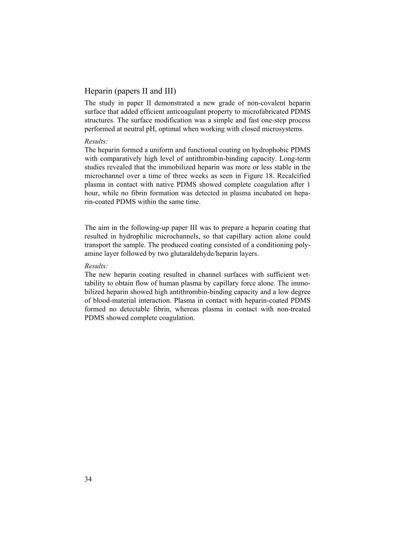
Heparin (papers II and III) The study in paper II demonstrated a new grade of non-covalent heparin surface that added efficient anticoagulant property to microfabricated PDMS structures. The surface modification was a simple and fast one-step process performed at neutral pH, optimal when working with closed microsystems.
Results:The heparin formed a uniform and functional coating on hydrophobic PDMS with comparatively high level of antithrombin-binding capacity. Long-term studies revealed that the immobilized heparin was more or less stable in the microchannel over a time of three weeks as seen in Figure 18. Recalcified plasma in contact with native PDMS showed complete coagulation after 1 hour, while no fibrin formation was detected in plasma incubated on hepa-rin-coated PDMS within the same time.
The aim in the following-up paper III was to prepare a heparin coating that resulted in hydrophilic microchannels, so that capillary action alone could transport the sample. The produced coating consisted of a conditioning poly-amine layer followed by two glutaraldehyde/heparin layers.
Results:The new heparin coating resulted in channel surfaces with sufficient wet-tability to obtain flow of human plasma by capillary force alone. The immo-bilized heparin showed high antithrombin-binding capacity and a low degree of blood-material interaction. Plasma in contact with heparin-coated PDMS formed no detectable fibrin, whereas plasma in contact with non-treated PDMS showed complete coagulation.

35
Figure 17. An irreversibly sealed PDMS structure was oxidized by placing the co-rona electrode tip in the reservoir at the channel beginning (left in picture). Lumi-nescence is the plasma discharge spreading inside the microchannel system (paper VIII).
Figure 18. Long-term evaluation of the heparin coating explored in paper III. Heprin-coated devices were stored with air-filled channels for increasing number of weeks. Each device was flushed with fluorophore-labeled antithrombin before con-focal microscopy scanning. (a) Directly after coating, t=0, (b) t=7 days, (c) t=14 days, and (d) t=21 days.
36
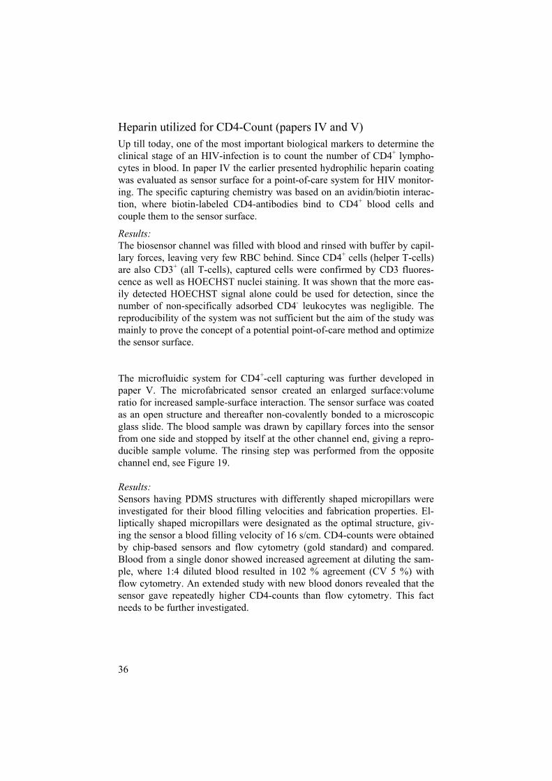
Heparin utilized for CD4-Count (papers IV and V) Up till today, one of the most important biological markers to determine the clinical stage of an HIV-infection is to count the number of CD4+ lympho-cytes in blood. In paper IV the earlier presented hydrophilic heparin coating was evaluated as sensor surface for a point-of-care system for HIV monitor-ing. The specific capturing chemistry was based on an avidin/biotin interac-tion, where biotin-labeled CD4-antibodies bind to CD4+ blood cells and couple them to the sensor surface.
Results:The biosensor channel was filled with blood and rinsed with buffer by capil-lary forces, leaving very few RBC behind. Since CD4+ cells (helper T-cells) are also CD3+ (all T-cells), captured cells were confirmed by CD3 fluores-cence as well as HOECHST nuclei staining. It was shown that the more eas-ily detected HOECHST signal alone could be used for detection, since the number of non-specifically adsorbed CD4- leukocytes was negligible. The reproducibility of the system was not sufficient but the aim of the study was mainly to prove the concept of a potential point-of-care method and optimize the sensor surface.
The microfluidic system for CD4+-cell capturing was further developed in paper V. The microfabricated sensor created an enlarged surface:volume ratio for increased sample-surface interaction. The sensor surface was coated as an open structure and thereafter non-covalently bonded to a microscopic glass slide. The blood sample was drawn by capillary forces into the sensor from one side and stopped by itself at the other channel end, giving a repro-ducible sample volume. The rinsing step was performed from the opposite channel end, see Figure 19.
Results:Sensors having PDMS structures with differently shaped micropillars were investigated for their blood filling velocities and fabrication properties. El-liptically shaped micropillars were designated as the optimal structure, giv-ing the sensor a blood filling velocity of 16 s/cm. CD4-counts were obtained by chip-based sensors and flow cytometry (gold standard) and compared. Blood from a single donor showed increased agreement at diluting the sam-ple, where 1:4 diluted blood resulted in 102 % agreement (CV 5 %) with flow cytometry. An extended study with new blood donors revealed that the sensor gave repeatedly higher CD4-counts than flow cytometry. This fact needs to be further investigated.

37
Figure 19. The concept of a HIV-monitoring point-of-care device. The PDMS part has elliptical shaped pillars to increase the surface:volume ratio and increase the capillary flow. Blood filled the channel from one side (left) and stopped when it reached the channel end (right). The device was rinsed by adding rinse buffer to the channel end on the right (paper V).
Figure 20. Evaluation of the HIV-sensor. The captured fluorescent cells in the sen-sor channels were counted by using the laser of a confocal microscope (left). The agreement of HOECHST+ and CD3+ signal from the captured cells was verified at random positions along the channels (right). Photos by Mikael Lindeberg.

38
Sample Injection and Detection Sample Injection and Fluid Flow (paper VIII) The aim of paper VIII was to fabricate a single device that included sample injection, separation and ESI-emitter modules and was produced in one PDMS bulk piece. The sample injection (double-T construction) and fluid pumping was EOF-driven, which normally needs costly high voltage/low-current relays. We explored if low-cost relays, which in our construction were limited to switch between ground, floating and HV at a maximum of 1.4 kV, were enough to accomplish the set-up chip functions.
Results:Some problems with instable spray were experienced due to low buffer flows. Accurate aligning of the device in front of the MS orifice was impor-tant. The set-up was shown successful with the use of low-cost relays; the electrospray performance was sufficient to detect a 10 µg/mL to some extent separated four-peptide sample under high pH-conditions and in positive ESI-mode.
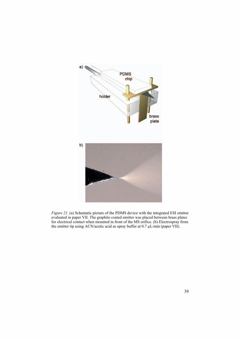
ESI-MS Detection (papers VII and VIII) The fabrication of an integrated PDMS ESI-emitter was described in paper VII (Figure 21). The study included measurements on emitter performance in the form of spray and electrical coating stability. The same emitter con-struction was used for the multifunctional device presented in paper VIII, as described above.
Results:Both the graphite powder coating for ESI contact and the bond between the PDMS substrates showed excellent durability, confirmed by both a long-term (800 h) ESI evaluation as well as a discharge investigation.
Negligible accumulation of electrolyte occurred at the microfabricated ESI emitter tip, which was proven by a successful CE-ESI-MS experiment. Even at low EOF flows the emitter showed a spray stability of 4.6 % RSD (total ion current).
39
Figure 21. (a) Schematic picture of the PDMS device with the integrated ESI emitter evaluated in paper VII. The graphite coated emitter was placed between brass plates for electrical contact when mounted in front of the MS orifice. (b) Electrospray from the emitter tip using ACN/acetic acid as spray buffer at 0.7 µL/min (paper VII).


41
Concluding Remarks and Outlook
My concise conclusions of the work behind this thesis are the following:
It is possible to integrate several functional chip modules into a single mi-crodevice and still utilize a low grade of fabrication complexity.
Low-complex modules in PDMS for blood separation, desalting, enrichment, separation and ESI-MS detection were successfully fabricated. Fabricating these modules into a single integrated microdevice would be desirable.
PDMS should be considered as the material of choice for future commercial systems. To my own opinion, PDMS structures are best exploited when their advantageous elastic and bonding properties are combined with other mate-rials, such as glass or various polymers.
PDMS is an excellent material to use when fabricating microdevice proto-types and studying their microfluidic behaviors. The instant oxidation method greatly sets aside the need of other surface modifications to over-come the problem of non-specific adsorption of PDMS.
The explored new method of embedding square capillaries and bond them with plasma treatment to PDMS opens up the possibility for including any function on-chip that can be incorporated into a silica capillary.
The different heparin coatings evaluated on PDMS are proven to generate microstructures compatible with complex biological samples like plasma and whole blood. The heparin with double-layer composition adds sought-after hydrophilicity, making it possible to fill and rinse the microstructures by pure capillarity.
The heparin surface has high potential as a biocompatible sensor surface for CD4-count. I find the construction of coating open PDMS substrates and reversibly seal them to e.g. a glass substrate appealing. The pillar-structures successfully increase the yield of cell capture from blood. For point-of-care application, the system must have a lower degree of manual operation and be evaluated for its long-term stability.


43
Personal Reflections
My expectations of working within the world of micro and lab-on-chips were high when I started my thesis work! They have not declined during the years, but they have changed direction a bit and of course become more down-to-earth. I guess that this happen to many of us who start with design-ing fancy microsystems, and end up struggling in the lab with problems that were not supposed to be any problems... But I tried to learn from those with more experience, i.e. who had already come to the I thought this would not be a problem-insight earlier than I did.
For example, I got to know from certain earlier group members that the bonding of polymer microsystems creates a lot of trouble, but is unfortu-nately not considered as very exciting research. So I thought I try to avoid the bonding difficulties. I had also learnt that generating injection molded substrates could take a while... this is how I started working with PDMS. It is a pity I haven’t counted all PDMS castings performed during this work; there are a couple of them!
Within the studied area, the era when the microfabrication in itself was the sole news has more or less come to an end. The integration and applica-tion of a microsystem in real life is today rightly of greater importance. I also see work within the area of lab-on-chip as very much applied research with commercial products as the aim in the end. I think research should be pushed further into using more clinical like samples and spend more time on things like on-chip sample preparation, macro/micro-connections, sample storage on-chip, bonding, stability in form of shelf-life time, mass fabrication as-pects, device costs, user-friendliness et cetera. I think these aspects will need more attention before commercial systems can be introduced, especially within the area of point-of-care.
In order to complete studies that include microfabrication as well as testing and evaluation of the systems, one needs to collaborate with people who are experts in various areas. I have experienced this as very joyful and encourag-ing, even if you realize that you yourself are never the expert in each specific area. I have also learnt that some non-microfabrication persons tend to be-lieve that everything is doable within microfabrication and on the contrary some microfabrication persons greatly underestimate the problem of work-ing with biological samples. Probably a well-known situation, but also the beauty, within all sorts of collaborative research!

44
I attended a thesis defense within the present area not too long ago, where the thesis opponent described the microdevices as ‘fabricated using the lab-on-chip technology’. Unfortunately, I must admit that I was not aware of this technology and that I fabricated and evaluated my devices the hard way dur-ing all years. If I had only known...
45
Summary in Swedish
I början på 90-talet infördes begreppet µTAS som översatt till svenska bety-der miniatyriserat totalt analyssystem. Tanken är att biokemiska analyser eller cellbiologiska studier som idag görs i storskaliga analyslab ska kunna utföras på flödeschip. Till skillnad från de mikrochip som används i t.ex. datorer så innehåller flödeschip små kanaler där prover kan transporteras, separeras, mixas och detekteras. Om dessa µTAS kan göras helt automatiska och därtill innehålla väldigt små volymer kan mycket tid och pengar sparas: många prover kan köras samtidigt, endast små volymer av dyra reagenser konsumeras, många processer som tar lång tid idag (provupparbetning, spädningar, centrifugering) kan integreras på microchipet o.s.v. Därtill upp-för sig vätskor i mikrokanaler annorlunda än i makrovärlden, vilket gör att nya typer av analyser och tillverkningsprocesser blir möjliga. Ett hett område inom mikrofluidikforskningen är att producera chip som kan användas så nära patienten som möjligt, och gärna av patienten själv, s.k. point-of-caresystem. Det kan handla om tester för t.ex. allergier, HIV, anabola steroider, malaria och blodglukosmätning.
Fram till idag finns det väldigt få exempel på robusta µTAS tillgängliga på marknaden. Även om grundforskningen inom mikrofluidik har kommit långt behöver de integrerade µTAS systemen göras mer användarvänliga; man ska inte behöva vara mikrofluidikexpert för att kunna använda syste-men. Därtill kräver många av dagens fungerande system ofta mycket extern utrustning såsom sprutpumpar och högspänningsaggregat.
De första åren producerades de flesta flödeschip i kisel eller glas mest bero-ende på att mikrofabriceringsmetoderna för dessa material redan fanns utar-betade inom halvledarindustrin. Med tiden har polymera material och plaster blivit allt vanligare eftersom tillverkningskostnaderna därmed kan reduceras. Alla strukturer som presenteras inom denna avhandling är producerade i det polymera materialet PDMS, poly(dimetylsiloxan). PDMS har framför allt blivit vanligt inom den akademiska forskningen p.g.a. den snabba och för-hållandevis billiga tillverkningsprocessen, men idag finns även kommersiella produkter inom mikrofluidik som är gjorda i PDMS.
Mitt mål med arbetet var att föra utvecklingen ett litet steg närmare framti-dens användarvänliga µTAS. Jag tror själv att lösningen ligger i att konstrue-ra så ”enkla” system som möjligt, d.v.s. okomplicerade konstruktioner som i

46
stor utsträckning består av ett och samma material och har så få lösa delar som möjligt. Jag har här visat att det är möjligt att integrera flera funktioner på ett och samma chip, men samtidigt bibehålla en låg grad av tillverknings-komplexitet. Avhandlingen beskriver lågkomplexa moduler i PDMS för blodseparation (artikel I), avsaltning (artikel VII), uppkoncentrering (artikel VI, VII), separation (artikel VIII) och elektrospray-joniserings masspektro-metri detektion (artikel VII, VIII). Det önskvärda vore nu att sätta samman alla dessa moduler i ett och samma fungerande system.
Jag har också kommit till insikten att PDMS inte nödvändigtvis behöver betraktas som ett material som enbart används inom forskningen och till prototyptillverkning. PDMS kommer framför allt till sin rätt om man utnytt-jar dess elastiska egenskap tillsammans med andra material, såsom glas eller andra polymerer. Just till prototyptillverkning har den beskrivna ICO-metoden (artikel IX) visat sig vara lämplig: metoden visar att man mycket snabbt och lätt kan oxidera förslutna kanaler och därmed minska den ospeci-fika inbindningen på kanalväggarna, något som annars är ett problem med PDMS materialet.
Ytterligare har vi genom den förenklade kapillärinsättningsmetoden (arti-kel VI) visat att det är möjligt att bygga in valfri funktion i ett PDMS-chip, så länge funktionen går att inkorporera i en silikakapillär.
En stor del av arbetet har bestått i att ta fram och utvärdera en biokompatibel mikrosystemyta. Det resulterade i två olika heparinytor (varianter av Corli-nes heparinyta); en yta som framför allt lämpar sig för slutna system efter-som den består av endast en lösning (artikel II), och en annan som är av fler-lagers-princip med hög vätbarhet (artikel III), vilket gör att den kan dra in plasma eller helblod i kanalen med enbart kapillära krafter, något som ofta är väldigt eftertraktat inom mikrofluidik.
Den andra heparinytan visade sig även högst lämplig för infångning av specifika celler i blodet (artikel IV). Vi valde att optimera infångningen av CD4-positiva T-lymfocyter. Det är framför allt dessa celler som minskar vid en HIV-infektion och antalet CD4+ celler i blodet är idag fortfarande en av de viktigaste parametrarna man mäter för att följa HIV-förloppet hos en smittad människa. Den modifierade PDMS-ytan visade sig fånga dessa celler väldigt specifikt med näst intill ingen inbindning av andra vita blodceller. Genom att med flödesriktiga pelarstrukturer markant öka ytan i mikrokana-len, ökade vi utbytet av infångade celler (artikel V). Systemet behöver testas med ett större antal kliniska prover och därtill göras mer automatiserat, men kan i förlängningen vara en prototyp till en HIV-sensor för patientnära bruk.
47
Acknowledgements
Det hade såklart varit mycket svårare och mindre roligt att få ihop en av-handling utan alla er andra! Lite särskilt varma tack till
mina handledare Jonas och Fredrik - för att ni gav mig chansen att börja här, för all hjälp, att ni hela tiden har trott på mig (i alla fall gett intrycket av!) och för att ni båda har schysst humor. Jag har helt klart haft kul!
Javier och Rolf för många trevliga men blodiga labdagar på Klinisk Immu-nologi - jag har verkligen uppskattat vårt samarbete och att få ha en fot kvar i biomaterialvärlden
alla i gruppen genom åren, Jonas, Malin, Micke, Oliver, David, Axel, Peter och Jan, för rumssällskap, goda råd och skoj…Rånäs inte att förglömma!
ett extra tack till Peter för att ha agerat superb labslav! Det blev bra många timmar Delirium i mörkrummet för att få till våra jääättefina provpluggar
alla i MedChip-konstellationen för att ha utgjort ett inspirerande forum och för att ha resulterat i spännande samarbeten - det kommer ju som tur är alltid ett nästa OS där vi kan testa våra dopingchip!
kollegor på Materialvetenskap, runt om på Ångan, ÅSTC-gänget, Analy-tisk Kemi och Klinisk Immunologi som gjort att jag har trivts och känt mig välkommen på de olika ställena
de ovärderliga personerna som får en doktorand att klara av pappersexercis och labstrul: bl.a. Carin, Caroline, Jan-Åke och Jan Grawé, även stort tack till MSL personalen för hjälp i renrummet
närmaste vänskaran som nog kan sammanfattas med gänget som träffas i fikarummet vid 17-tiden för en stöd-macka: tack för gott kamratskap, rese-sällskap, köksbygge, simbassängslängder…

48
ni andra civila vänner, ingen nämnd ingen glömd, som gör mig glad utanför universitets väggar
naturligtvis mamma, pappa och Lina för allt från att ha hittat annonsen (sant!) till att vara precis de ni är
förmodligen bästa killen på jorden, Mats, för att du har ett stort hjärta, kan typ allt om mikrochip som jag frågar om, har de finaste lockarna och för att du sparade mina nerver och till slut fick ihop din bok! Du är bäst!
Massor tack till er alla!

49
References
1. Manz A, Graber N and Widmer HM, Miniaturized total chemical analysis systems: A novel concept for chemical sensing. Sensors and Actuators B: Chemical 1(1-6): 244-248, 1990.
2. Janasek D, Franzke J and Manz A, Scaling and the design of minia-turized chemical-analysis systems. Nature 442(7101): 374-380, 2006.
3. Reyes DR, Iossifidis D, Auroux P-A and Manz A, Micro Total Analy-sis Systems. 1. Introduction, Theory, and Technology. AnalyticalChemistry 74(12): 2623-2636, 2002.
4. Auroux P-A, Iossifidis D, Reyes D and Manz A, Micro Total Analysis Systems. 2. Analytical Standard Operations and Applications. Analyti-cal Chemistry 74(12): 2637-2652, 2002.
5. Fiorini GS and Chiu DT, Disposable microfluidic devices: fabrication, function, and application. Biotechniques 38(3): 429-446, 2005.
6. Erickson D and Li DQ, Integrated microfluidic devices. AnalyticaChimica Acta 507(1): 11-26, 2004.
7. Verpoorte E and De Rooij NF, Microfluidics meets MEMS. Proceed-ings of the IEEE 91(6): 930-953, 2003.
8. Whitesides GM, The origins and the future of microfluidics. Nature442(7101): 368-373, 2006.
9. Dittrich PS, Tachikawa K and Manz A, Micro Total Analysis Systems. Latest Advancements and Trends. Analytical Chemistry 78(12): 3887-3908, 2006.
10. Beebe D and Folch A, The science and applications of cell biology in microsystems. Lab on a Chip 5(1): 10-11, 2005.
11. Andersson H and van den Berg A, Where are the biologists? Lab on a Chip 6(4): 467-470, 2006.
12. Andersson H and van den Berg A, Microfluidic devices for cellomics: a review. Sensors and Actuators B: Chemical 92(3): 315-325, 2003.
13. El-Ali J, Sorger PK and Jensen KF, Cells on chips. Nature 442(7101): 403-411, 2006.
14. Becker H and Locascio LE, Polymer microfluidic devices. Talanta56(2): 267-287, 2002.
15. Becker H and Gartner C, Polymer microfabrication methods for micro-fluidic analytical applications. Electrophoresis 21(1): 12-26, 2000.
16. Unger MA, Chou HP, Thorsen T, Scherer A and Quake SR, Monolithic microfabricated valves and pumps by multilayer soft lithography. Sci-ence 288(5463): 113-116, 2000.
17. Grover WH, Skelley AM, Liu CN, Lagally ET and Mathies RA, Mono-lithic membrane valves and diaphragm pumps for practical large-scale

50
integration into glass microfluidic devices. Sensors and Actuators B-Chemical 89(3): 315-323, 2003.
18. Ng JMK, Gitlin I, Stroock AD and Whitesides GM, Components for integrated poly(dimethylsiloxane) microfluidic systems. Electrophore-sis 23(20): 3461-3473, 2002.
19. Breslauer DN, Lee PJ and Lee LP, Microfluidics-based systems biol-ogy. Molecular Biosystems 2(2): 97-112, 2006.
20. Toner M and Irimia D, Blood-on-a-chip. Annual Review of Biomedical Engineering 7: 77-103, 2005.
21. Bashir R, BioMEMS: state-of-the-art in detection, opportunities and prospects. Advanced Drug Delivery Reviews 56(11): 1565-1586, 2004.
22. Kling J, Moving diagnostics from the bench to the bedside. Nature Biotechnology 24(8): 891-893, 2006.
23. Hogan J, Lab on a chip: A little goes a long way. Nature 442(7101):351-352, 2006.
24. Mitchell P, Microfluidics - downsizing large-scale biology. Nature Biotechnology 19(8): 717-721, 2001.
25. Ehrenkranz JRL, Home and point-of-care pregnancy tests: A review of the technology. Epidemiology 13(3): S15-S18, 2002.
26. Engler KH, Efstratiou A, Norn D, Kozlov RS, Selga I, Glushkevich TG, Tam M, Melnikov VG, Mazurova IK, Kim VE, Tseneva GY, Ti-tov LP and George RC, Immunochromatographic Strip Test for Rapid Detection of Diphtheria Toxin: Description and Multicenter Evaluation in Areas of Low and High Prevalence of Diphtheria. Journal of Clini-cal Microbiology 40(1): 80-83, 2002.
27. Zarakolu P, Buchanan I, Tam M, Smith K and Hook III EW, Prelimi-nary Evaluation of an Immunochromatographic Strip Test for Specific Treponema pallidum Antibodies. Journal of Clinical Microbiology40(8): 3064-3065, 2002.
28. Pichini S, Navarro M, Farre M, Ortuno J, Roset PN, Pacifici R, Zuc-caro P, Segura J and de la Torre R, On-Site Testing of 3,4-Methylenedioxymethamphetamine (Ecstasy) in Saliva with Drugwipe and Drugread: A Controlled Study in Recreational Users. ClinicalChemistry 48(1): 174-176, 2002.
29. Garg S, Potts R, Ackerman N, Fermi S, Tamada J and Chase H, Corre-lation of fingerstick blood glucose measurements with GlucoWatch bi-ographer glucose results in young subjects with type 1 diabetes. Diabe-tes Care 22(10): 1708-1714, 1999.
30. Yager P, Edwards T, Fu E, Helton K, Nelson K, Tam MR and Weigl BH, Microfluidic diagnostic technologies for global public health. Nature 442(7101): 412-418, 2006.
31. www.gyros.se. 2006. 32. www.4castchip.se. 2006. 33. Campbell DJ, Beckman KJ, Calderon CE, Doolan PW, Ottosen RM,
Ellis AB and Lisensky GC, Replication and compression of bulk and surface structures with polydimethylsiloxane elastomer. Journal of Chemical Education 76(4): 537-541, 1999.

51
34. Wacker Chemie Product Information Elastosil RT601. 2006. 35. Dow Corning Product Information Sylgard 184. 2006. 36. Duffy DC, McDonald JC, Schueller OJA and Whitesides GM, Rapid
prototyping of microfluidic systems in poly(dimethylsiloxane). Ana-lytical Chemistry 70(23): 4974-4984, 1998.
37. McDonald JC and Whitesides GM, Poly(dimethylsiloxane) as a mate-rial for fabricating microfluidic devices. Accounts of Chemical Re-search 35(7): 491-499, 2002.
38. Sia SK and Whitesides GM, Microfluidic devices fabricated in poly(dimethylsiloxane) for biological studies. Electrophoresis 24(21):3563-3576, 2003.
39. McDonald JC, Duffy DC, Anderson JR, Chiu DT, Wu HK, Schueller OJA and Whitesides GM, Fabrication of microfluidic systems in poly(dimethylsiloxane). Electrophoresis 21(1): 27-40, 2000.
40. Makamba H, Kim JH, Lim K, Park N and Hahn JH, Surface modifica-tion of poly(dimethylsiloxane) microchannels. Electrophoresis 24(21):3607-3619, 2003.
41. Jo BH, Van Lerberghe LM, Motsegood KM and Beebe DJ, Three-dimensional micro-channel fabrication in polydimethylsiloxane (PDMS) elastomer. Journal of Microelectromechanical Systems 9(1):76-81, 2000.
42. Pihl J, Sinclair J, Sahlin E, Karlsson M, Petterson F, Olofsson J and Orwar O, Microfluidic gradient-generating device for pharmacological profiling. Analytical Chemistry 77(13): 3897-3903, 2005.
43. Sinclair J, Pihl J, Olofsson J, Karlsson M, Jardemark K, Chiu DT and Orwar O, A cell-based bar code reader for high-throughput screening of ion channel-ligand interactions. Analytical Chemistry 74(24): 6133-6138, 2002.
44. www.cellectricon.se, Commercial PDMS products. 2006. 45. www.biacore.com, Commercial PDMS products. 2006. 46. www.fluidigm.com, Commercial PDMS products. 2006. 47. Ratner BD, Biomaterials science an introduction to materials in medi-
cine. Academic Press, San Diego, 1996. 48. Hunt BJ, Parratt R, Cable M, Finch D and Yacoub M, Activation of
coagulation and platelets is affected by the hydrophobicity of artificial surfaces. Blood Coagulation & Fibrinolysis 8(4): 223-231, 1997.
49. Vince DG, Hunt JA and Williams DF, Quantitative Assessment of the Tissue-Response to Implanted Biomaterials. Biomaterials 12(8): 731-736, 1991.
50. Nygren H and Eriksson C, Experimental approach to a biological char-acterization of materials. Journal of Vacuum Science & Technology A-Vacuum Surfaces and Films 15(3): 768-772, 1997.
51. Chen H, Chen Y, Sheardown H and Brook MA, Immobilization of heparin on a silicone surface through a heterobifunctional PEG spacer. Biomaterials 26(35): 7418-7424, 2005.
52. Sanchez J, Elgue G, Riesenfeld J and Olsson P, Inhibition of the plasma contact activation system of immobilized heparin: Relation to

52
surface density of functional antithrombin binding sites. Journal of Biomedical Materials Research 37(1): 37-42, 1997.
53. Christensen K, Larsson R, Emanuelsson H, Elgue G and Larsson A, Heparin coating of the stent graft - effects on platelets, coagulation and complement activation. Biomaterials 22(4): 349-355, 2001.
54. van Der Giessen WJ, van Beusekom HM, Larsson R and Serruys P, Heparin-Coated Coronary Stents. Curr Interv Cardiol Rep 1(3): 234-240, 1999.
55. Fenn JB, Mann M, Meng CK, Wong SF and Whitehouse CM, Elec-trospray Ionization for Mass-Spectrometry of Large Biomolecules. Sci-ence 246(4926): 64-71, 1989.
56. Bruins AP, Mechanistic aspects of electrospray ionization. Journal of Chromatography A 794(1-2): 345-357, 1998.
57. de Mello AJ, Chip-MS: Coupling the large with the small. Lab on a chip (1): 7-12, 2001.
58. Barnidge DR, Nilsson S and Markides KE, A design for low-flow sheathless electrospray emitters. Analytical Chemistry 71(19): 4115-4118, 1999.
59. Nilsson S, Wetterhall M, Bergquist J, Nyholm L and Markides KE, A simple and robust conductive graphite coating for sheathless electros-pray emitters used in capillary electrophoresis/mass spectrometry. Rapid Communications in Mass Spectrometry 15(21): 1997-2000, 2001.
60. Dahlin AP, Wetterhall M, Liljegren G, Bergstrom SK, Andren P, Ny-holm L, Markides KE and Bergquist J, Capillary electrophoresis cou-pled to mass spectrometry from a polymer modified poly(dimethylsiloxane) microchip with an integrated graphite electros-pray tip. Analyst 130(2): 193-199, 2005.
61. Sauerbrey G, Use of crystal oscillators for weighing thin films and for microweighing. Zeitschrift fuer Physik 155(2): 206-222, 1959.
62. Hook F, Rodahl M, Brzezinski P and Kasemo B, Energy dissipation kinetics for protein and antibody-antigen adsorption under shear oscil-lation on a quartz crystal microbalance. Langmuir 14(4): 729-734, 1998.
63. Rodahl M, Hook F, Krozer A, Brzezinski P and Kasemo B, Quartz-Crystal Microbalance Setup for Frequency and Q-Factor Measurements in Gaseous and Liquid Environments. Review of Scientific Instruments66(7): 3924-3930, 1995.
64. www.chemsoc.org, Electroosmotic flow theory. 2006.


Acta Universitatis UpsaliensisDigital Comprehensive Summaries of Uppsala Dissertationsfrom the Faculty of Science and Technology 241
Editor: The Dean of the Faculty of Science and Technology
A doctoral dissertation from the Faculty of Science andTechnology, Uppsala University, is usually a summary of anumber of papers. A few copies of the complete dissertationare kept at major Swedish research libraries, while thesummary alone is distributed internationally through theseries Digital Comprehensive Summaries of UppsalaDissertations from the Faculty of Science and Technology.(Prior to January, 2005, the series was published under thetitle “Comprehensive Summaries of Uppsala Dissertationsfrom the Faculty of Science and Technology”.)
Distribution: publications.uu.seurn:nbn:se:uu:diva-7270
ACTAUNIVERSITATISUPSALIENSISUPPSALA2006


