
Microfibrous Entrapped Catalyst Structure for Alternative ... · Structure for Alternative Fuel...
22
- Proprietary and Business Sensitive - M icrof ibrous E ntrapped C atalyst (MFEC) Structure for Alternative Fuel Production Hongyun Yang 1 , Symon Sheng 2 , Norman E. Sammons Jr. 1 , Troy J. Barron 1 and Bruce J. Tatarchuk 2 , (1)IntraMicron Inc., Auburn, AL, (2)Center for Microfibrous Materials, Auburn University November 11, 2010 AIChE 2010 Annual Meeting, Salt Lake City, Utah 1
Transcript of Microfibrous Entrapped Catalyst Structure for Alternative ... · Structure for Alternative Fuel...

- Proprietary and Business Sensitive -
Microfibrous Entrapped Catalyst (MFEC) Structure for Alternative Fuel Production
Hongyun Yang 1, Symon Sheng 2, Norman E. Sammons Jr.1, Troy J. Barron 1 and Bruce J. Tatarchuk 2,
(1)IntraMicron Inc., Auburn, AL, (2)Center for Microfibrous Materials, Auburn University
November 11, 2010
AIChE 2010 Annual Meeting, Salt Lake City, Utah
1

- Proprietary and Business Sensitive -
Outline
• Introduction– IntraMicron– Alternative Fuels
• MFEC – Mass Transfer– Heat transfer– Reduced BOP
• Summary• Acknowledgement
2
- Proprietary and Business Sensitive - 3
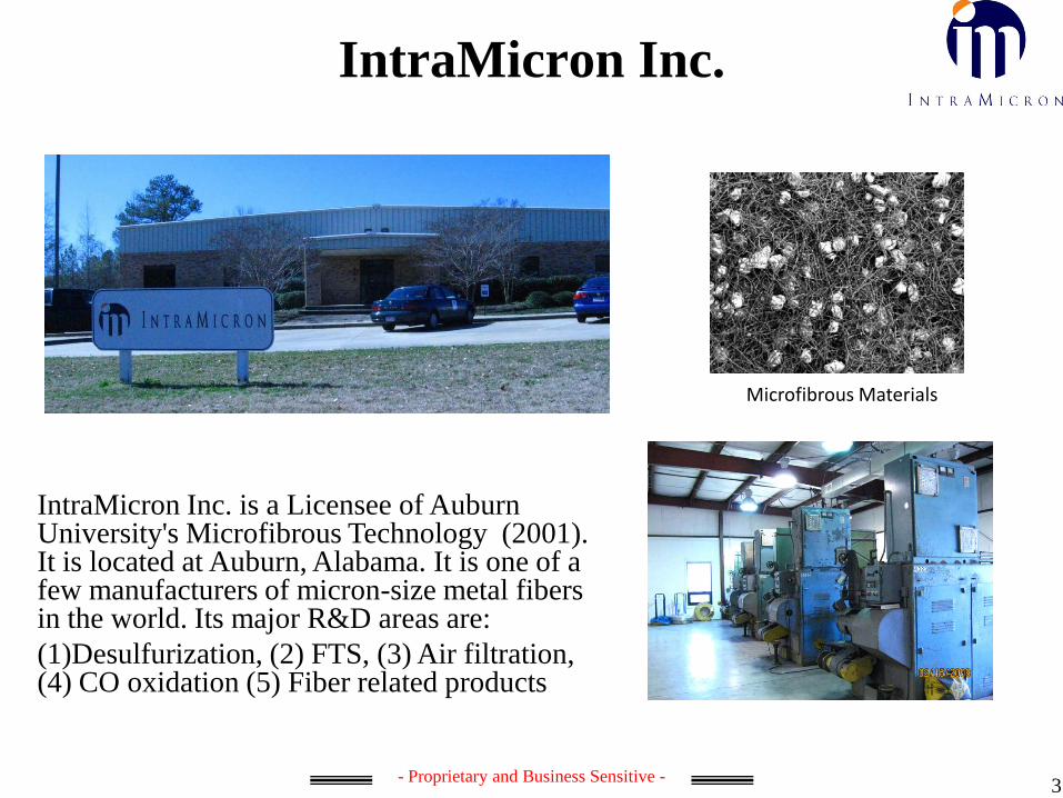
IntraMicron Inc.
IntraMicron Inc. is a Licensee of Auburn University's Microfibrous Technology (2001). It is located at Auburn, Alabama. It is one of a few manufacturers of micron-size metal fibers in the world. Its major R&D areas are:(1)Desulfurization, (2) FTS, (3) Air filtration, (4) CO oxidation (5) Fiber related products
Microfibrous Materials
- Proprietary and Business Sensitive -
Introduction• Fossil Fuels and Alternative Fuels
– Petroleum based liquid fuels• Fuel infrastructure based on liquid fuel• Limited reservoir (84 million bpd for 44 years)
– Alternative sources• Natural Gas (NG), Coal• Solar, Wind, Tide, Geothermal, Biomass, Nuclear
• Alternative Liquid Fuels– Synfuels (high quality, gasoline, jet fuel, diesel)– Methanol and ethanol– Biodiesel
4

- Proprietary and Business Sensitive -
Alternative Fuel Production by XTL
5
Syngas
FTS
Methanol Synthesis
MTG
Gasoline
Jet Fuel
Diesel
NG
Coal
Biomass
Other alternative energy sources that provides CO, H2 or syngas
Small scale GTL and BTL units are of significant research interests(1)Stranded small scale NG reservoirs(2)Small scale BTL units(3)Good modularity and mobility
Methanol
"Conventional GTL technologies are not economically viable at small scales of less than 10 000 barrels of oil per day (bpd). However, only about 6% of the world's gas fields are large enough to sustain a GTL plant of that size.” CTO of Oxford Catalyst Group
DME

- Proprietary and Business Sensitive -
Exothermic Reactions• Fischer-Tropsch Synthesis
– CO+H2=-CH2- +H2O ∆H= -165kJ/mol Tadiabatic=1750 C– Co (LTFTS) and Fe (HTFTS)– Polymerization nature– Selectivity vs. temperature– Catalyst deactivation and thermal runaway
• Methanol Formation– CO+2H2=CH3OH ∆H= -124kJ/mol Tadiabatic=1370 C– Cu-ZnO/Al2O3
– Reverse reaction of methanol reforming– Catalyst deactivation and methanol reforming at high temperatures
The need of fast heat removal vs. low effective thermal conductivity of packed beds (0.0x-0.2 W/k-m)
6

- Proprietary and Business Sensitive -
Industry Reactors• Packed Beds
– High gas velocity and low single pass conversion– Multiple thin tubes
• Fluidized Beds• Slurry Phase Reactors
7
Novel Reactors: Microchannel, Honeycomb reactors, MFEC Reactor
Conventional reactors are large.
- Proprietary and Business Sensitive -
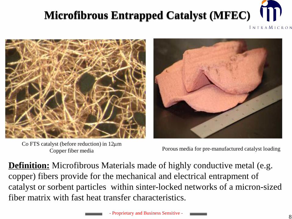
Microfibrous Entrapped Catalyst (MFEC)
Co FTS catalyst (before reduction) in 12µm Copper fiber media Porous media for pre-manufactured catalyst loading
Definition: Microfibrous Materials made of highly conductive metal (e.g. copper) fibers provide for the mechanical and electrical entrapment of catalyst or sorbent particles within sinter-locked networks of a micron-sized fiber matrix with fast heat transfer characteristics.
8
- Proprietary and Business Sensitive -
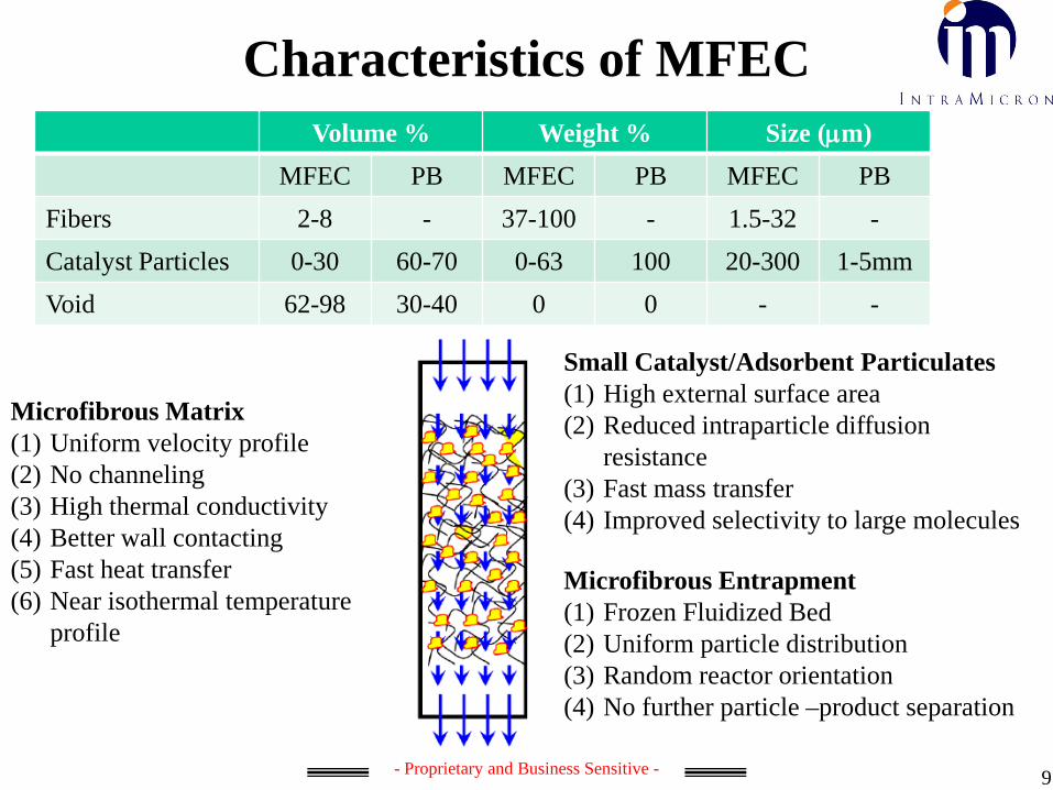
Characteristics of MFECVolume % Weight % Size (µm)
MFEC PB MFEC PB MFEC PBFibers 2-8 - 37-100 - 1.5-32 -Catalyst Particles 0-30 60-70 0-63 100 20-300 1-5mmVoid 62-98 30-40 0 0 - -
9
Microfibrous Matrix(1) Uniform velocity profile(2) No channeling(3) High thermal conductivity(4) Better wall contacting(5) Fast heat transfer(6) Near isothermal temperature
profile
Small Catalyst/Adsorbent Particulates(1) High external surface area(2) Reduced intraparticle diffusion
resistance(3) Fast mass transfer(4) Improved selectivity to large molecules
Microfibrous Entrapment(1) Frozen Fluidized Bed(2) Uniform particle distribution(3) Random reactor orientation(4) No further particle –product separation
- Proprietary and Business Sensitive - 10
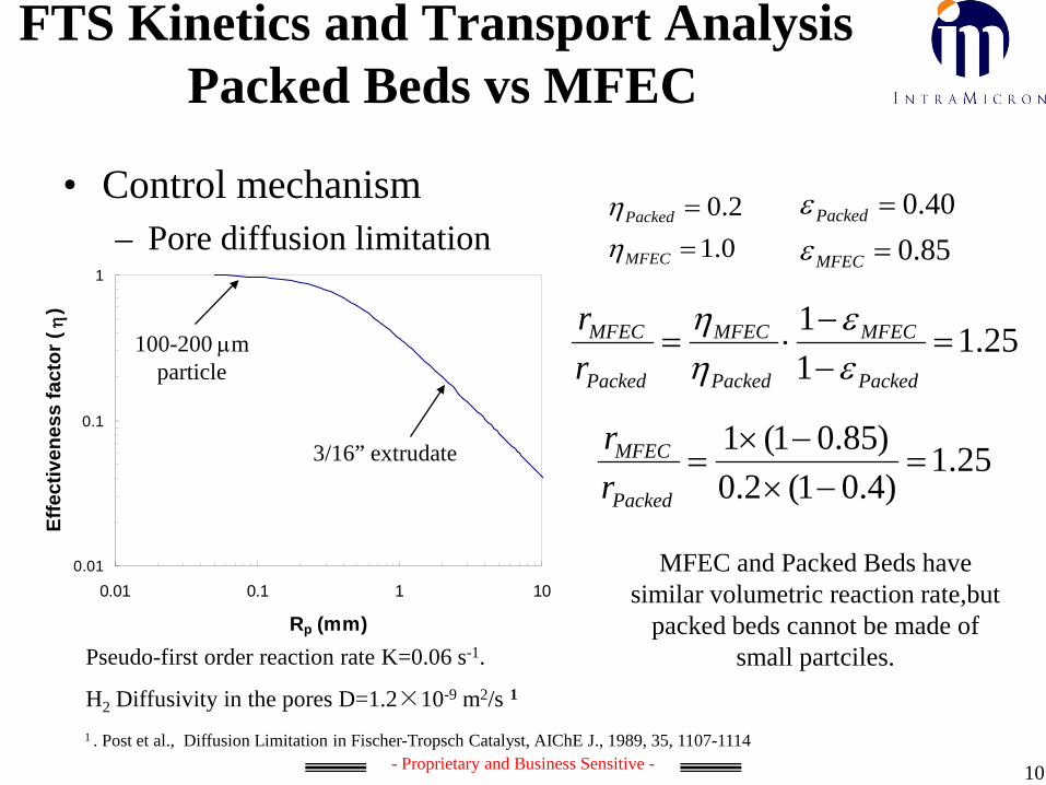
• Control mechanism– Pore diffusion limitation
FTS Kinetics and Transport AnalysisPacked Beds vs MFEC
0.12.0
==
MFEC
Packed
ηη
Pseudo-first order reaction rate K=0.06 s-1.
H2 Diffusivity in the pores D=1.2×10⁻⁹ m2/s 1
25.111
=−−
⋅=Packed
MFEC
Packed
MFEC
Packed
MFEC
rr
εε
ηη
0.01
0.1
1
0.01 0.1 1 10
Rp (mm)
Effe
ctiv
enes
s fa
ctor
(η
)
100-200 µm particle
3/16” extrudate
1 . Post et al., Diffusion Limitation in Fischer-Tropsch Catalyst, AIChE J., 1989, 35, 1107-1114
85.040.0
==
MFEC
Packed
εε
MFEC and Packed Beds have similar volumetric reaction rate,but
packed beds cannot be made of small partciles.
25.1)4.01(2.0)85.01(1=
−×−×
=Packed
MFEC
rr
- Proprietary and Business Sensitive -
0
10
20
30
40
50
60
70
80
90
100
0 100 200 300 400 500
Tem
pera
ture
chan
ge a
t Poi
nt 3
/˚C
Time /s
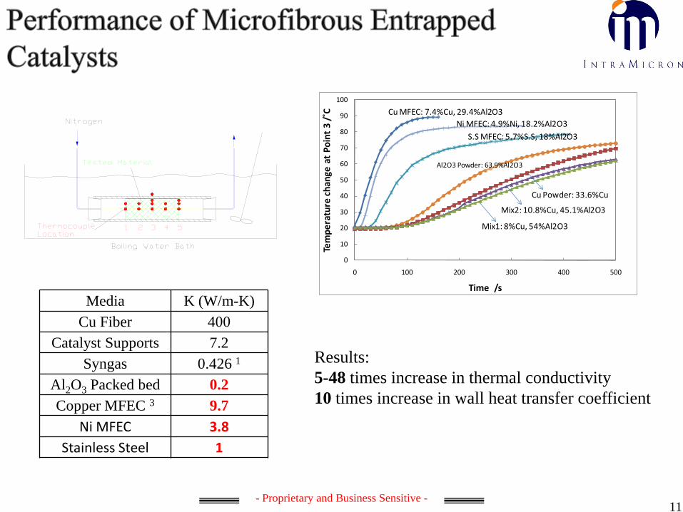
Cu MFEC: 7.4%Cu, 29.4%Al2O3 Ni MFEC: 4.9%Ni, 18.2%Al2O3
Al2O3 Powder: 63.9%Al2O3
Mix2: 10.8%Cu, 45.1%Al2O3
S.S MFEC: 5.7%S.S, 18%Al2O3
Mix1: 8%Cu, 54%Al2O3
Cu Powder: 33.6%Cu
Media K (W/m-K)Cu Fiber 400
Catalyst Supports 7.2Syngas 0.426 1
Al2O3 Packed bed 0.2Copper MFEC 3 9.7
Ni MFEC 3.8Stainless Steel 1
Results:5-48 times increase in thermal conductivity10 times increase in wall heat transfer coefficient
11

- Proprietary and Business Sensitive -
N2 @0.2m/s
N2 @0.05m/s
Velocity and Temperature Profile
Microfibrous Bed(20 vol.%)
Packed Bed (60 vol.%)
Packed Bed (60 vol.%)
Microfibrous Bed(20 vol.%)
Velocity Profile Temperature Profile
Compared to Packed Bed, Microfibrous bed provides much uniform temperature and velocity profile inside the bed. Thus, reaction can be considered to take place in a near-isothermal, plug flow condition.
12

- Proprietary and Business Sensitive - 13
Cu MFEC Performance in FTS Centerline temperature rise from reactor wall• ¾ inch O.D. downflow reactor, 15% Co/Al2O3 Pressure 20bar; • Utilize a 1/8 inch 6-point thermocouple to indicate the temperature profile at centerline during the
FTS reaction;• PB was diluted with fresh alumina to same catalyst density; • Same catalyst bed volume, 15.7cc(2.5g), locates from point 3 to 6,
Packed Bed Copper MFECflow rate /h-1 830.4 830.4
Wall T /˚C 225 235Conversion 0.543 0.538
Point Location T /˚C T-Twall /˚C T /˚C T-Twall /˚CGasheat Up
1 216.4 -8.6 226.5 -8.52 219.6 -5.4 228.5 -6.53 222.6 -2.4 232.2 -2.8
reaction Section
4 228.7 3.7 234.9 -0.15 231.9 6.9 237.1 2.16 229.5 4.5 235.8 0.8
Average 4~6 230.03 5.03 235.93 0.93
Centerline temperature rise from reactor wall (T-Twall) @ steady state reaction
Tc≈TwallAlpha_220C=0.86

- Proprietary and Business Sensitive - 14
0
0.02
0.04
0.06
0.08
0 10 20 30 40 50
Carbon number
Wei
ght f
ract
ion
MFECPacked bed
Assumptions:(1) Plug flow, (2) Temperature gradient in packed bed is 50 C and that in MFEC is 8 C w/ 5vol% fiberCalculation based on Ru catalyst, ASF model : (Mi molar fraction of Ci)
ASF FTS Product Distribution
)165(00343.01 −⋅−= Tα1)-(i
i )-(1M αα ⋅=
Same reactor diameter
Same inner wall temperature
(T in C) 1
1. Fit to Ru data in Fig. 13 pg. 275, Catal. Rev. Sci. Eng., 41(3&4), 255-318 (1999).
wall temperature: 200C
H2:CO=2.07
0
10
20
30
40
50
60
-2.54 -1.27 0 1.27 2.54
r(cm)
∆T
(°C)
Packed bedMFEC

- Proprietary and Business Sensitive -
Large Reactor Size
0.0
2.0
4.0
6.0
8.0
10.0
12.0
0 2 4 6 8 10
Max
imum
Tem
p D
iffer
ence
(deg
C)
ID of reactor (inches)
Co 220C
For Packed Bed Tubular Reactor:reactor size limitation: ID<10mm without gas recycle[5] , ID<80mm with gas recycle[19]. Typical reactor tube id is no greater than 2 inches.
For MFEC Tubular Reactor :No recycleMax. ID for LT Co: 8 inches (20 cm)Criteria: selectivity to JP5 drops to 95% of the highest possible selectivity at optimized reaction conditions.
Part count of MFEC FT reactor is 1/16 of a typical FT reactor of 2” ID.
ARGE Reactor (500 bpd) has 2050 tubes.
Storch et al 1951. The fischer-tropsch and related synthesis, John wiley & sons, New YorkVan Vuuren 1982. CSIR CENG 432
15

- Proprietary and Business Sensitive - 16
Balance of Plant (BOP) Case Study
• Cases for producing JP5 only (J)– Packed Bed (J-PB)– MFEC (J-MFEC)
• Cases for producing JP5 and light naphtha (C5-C8)– Packed Bed (J+L-PB)– MFEC (J+L-MFEC)
• Single pass cases (SP): no light hydrocarbon recycle– Packed Bed (SP-PB)– MFEC (SP-MFEC)

- Proprietary and Business Sensitive - 17
ASPEN Flow Sheet for FTS
S7
L-S1
H-S1
W-3
DC1-FEED
L-S3
H-S2
DC1JP5
CR-H2
CR-FEED
S9 DC2-FEED
L-S4
DC2JP5
H-S3
RECYC1RECYC2
FEED
S2
S8
L-S2
FTSFEED
FTS-PROD
COLDSYNG
W-1
W-2
S6
S3
STEAM-T
AS-S6AS-FTSFE
S4
AS-LS1AS-LS2
S5
C-W-1H-W-1
C-W-2
H-W-2
CONSEN-2
DC1
CRACKER
DC2
REFORMER
FEEDMIXV1
V2
P1
V3
COMP1
AS-HX-3FTS
CONDEN-1
HX-1
HX-2AS-HX-2
HX-3
HX-4
HX-5
HX-6
C-W-3
H-W-3
STEAM
JP5-MIX
HX-7
S10
JP5
C-W-4
H-W-4
DC1GAS
DC2GAS
GAS-MIX
S11
HX-8
GASOLINE
C-W-5H-W-5
In case JP’s, all dashed blue lines and
connected units are removed
In Case SP’s, all lines and units in the
shadowed area are removed

- Proprietary and Business Sensitive -
Reduce Balance of Plant
18
Case # BOP J-PB J-MFEC J+L-PB J+L-MFEC SP-PB SP-MFEC
FTS 1Wt. (t) 177 126 105 82 60 54
Vol. (m3) 135 103 80 66 43 43
CrackerWt. (t) 1.9 2.4 1.7 2.1 1.3 1.4
Vol. (m3) 2.3 3.5 1.8 2.8 0.85 1.1
Heat Exchanger
Wt. (t) 6.5 5.2 4.7 3.8 3 3
Vol. (m3) 7.1 5.2 4.7 3.5 2.7 2.7
ColumnWt. (t) 6.7 5.9 5.3 5.3 4.0 4.0
Vol. (m3) 13.9 11.4 8.6 8.6 4.3 4.4
Other Steam reformer, compressors, valves, condensers, pumps and pipes are not included
TotalWt. (t) 192 139 116 93 68 62
Vol. (m3) 158 123 95 81 75 75
Productbbd
Jet fuel 500 500 300 333 140 185
C5-C8 200 167 95 85

- Proprietary and Business Sensitive -
Other Applications
• Other Exothermic Reactions/Processes– Methanol, maleic anhydride, phthalic anhydride,
formaldehyde, acrylonitrile, acrylic acid, 1,2-dichloroethane, and vinyl chloride, air compression, concentrated acid dilution, vapor condensation
• Other Endothermic Reactions/Processes– steam methane reforming and liquid evaporation
19

- Proprietary and Business Sensitive -
Summary
• MFEC can reduced the catalyst loading by using small sized particles.
• MFEC can provide near-isothermal temperature profile inside the reactor.
• MFEC bed can provide temperature control and improve the product selectivity.
• BOP of alternative fuel production platforms can be reduced and more logistic.
20
- Proprietary and Business Sensitive -
Acknowledgement
21
This work is supported by U.S. Navy Contract N00014-09-C-0208.
- Proprietary and Business Sensitive -
Questions?
22


![Multicast Forwarding Equivalence Class [MFEC] · Multicast Forwarding Equivalence Class [MFEC] draft-guo-mboned-mfec-framework-00.txt ... draft-guo-mboned-mfe#3BD80F.ppt](https://static.fdocuments.us/doc/165x107/5af7dfda7f8b9a5b1e910ed6/multicast-forwarding-equivalence-class-mfec-forwarding-equivalence-class-mfec.jpg)


