Microcontroller programming for IVRS system PIC microcontroller

1
Microcontroller Control System for Heart Valve Bioreactor
A Design Project Report
Presented to the School of Electrical and Computer
Engineering of Cornell University
In Partial Fulfillment of the Requirements for the Degree of
Master of Engineering, Electrical and Computer Engineering
Submitted by Kang Li (kl694)
MEng Field Advisor: Bruce Robert Land
Degree Date: January 2015

2
Abstract
Master of Engineering Program
School of Electrical and Computer Engineering
Cornell University
Design Project Report
Project Title: Microcontroller control system for heart valve bioreactor
Author: Kang Li (kl694)
Abstract:
The project team of Butcher Lab has developed a bioreactor culture system to mimic the cardiac
cycle for the invitro conditioning of 3D printed tissue engineered heart valve conduits. I designed
a microcontroller control system to control the flow of the whole system and collect data sent
from transducers. This will help the bio-print team to investigate cell and construct function
under dynamic, physiological conditions and do further research.
I designed a microcontroller control system for the heart valve bioreactor using ATmega 1284P
microcontroller. It can control the flow of the whole system based on the specified parameters
and collect data in MATLAB. This will help Butcher Lab do further analysis.

3
Executive Summary
This project continues the design and development of a cyclic flow heart valve bioreactor for use
in culturing and conditioning of tissue engineered heart valves in the Butcher Lab in BME
department. The bioreactor can simulate the flow between left ventricle and aorta of the heart
to mechanically stimulate the cells of the tissue engineered aortic semi lunar heart valve.
My part in this project is to design a microcontroller control system for the heart valve bioreactor.
It can control the flow of the whole system based on the specified parameters and collect data in
MATLAB.
I use the built-in ADC of ATmega 1284P microcontroller. The microcontroller reads the signal of
four pressure transducers: high tank, low tank, ventricle, and aorta. And the microcontroller has
to control one pump and one solenoid valve. The pump is turned on/off based on the pressure
difference between high tank and low tank: if the pressure difference exceeds the upper
threshold, the pump will stop working; if the pressure difference is smaller than the lower
threshold, the pump will start working. The two-way solenoid valve is controlled based on the
pressure of aorta. If the pressure of aorta exceeds the threshold, the valve will be open;
otherwise it will be closed. And I built two junction boxes for controlling the pump and the
two-way solenoid valve. The junction boxes can connect the low power and the high power by
using relay switch. It can make the project safe to use. In this way, we can control the flow inside
the microcontroller to mimic the actual flow in the heart valve system of human.
The values of the thresholds differ every time we run the bioreactor. I use MATLAB to
communicate with the microcontroller. MATLAB sends different commands to the microcontroller
and the microcontroller will give feedback based on the commands. The user can check the
current state of the whole system, change the values of the parameters and collect data using
MATLAB. During data collection, MATLAB will plot real-time wave forms of the four transducers.
After finishing the data collection, MATLAB will store the data for further analysis.
The future work could be that we can design our own prototype board instead of using bread
board so the whole system could be more compact. And also, we can build several parallel TEHV
chambers instead of just one.

Content
1
Content
Introduction ..................................................................................................................................... 1
High Level Design ........................................................................................................................... 4
Hardware design ............................................................................................................................. 6
Software design ............................................................................................................................... 9
Microcontroller Part ....................................................................................................................... 9
1. TRT (Tiny Real Time) .................................................................................................... 9
2. Internal ADC of ATmega 1284P .................................................................................. 11
MATLAB Part ............................................................................................................................... 13
Result and Analysis ....................................................................................................................... 16
Conclusion ..................................................................................................................................... 17
Acknowledgement ......................................................................................................................... 17
APPENDIX A User Manual ...................................................................................................... 18
1. Hardware setup ............................................................................................................ 18
2. Run MATLAB code ...................................................................................................... 18
APPENDIX B Parts Number .................................................................................................... 21
APPENDIX C Source Code....................................................................................................... 22
pump_trt_28.c ....................................................................................................................... 22
Heart_valve-MCU.m ............................................................................................................. 29
Microcontroller Control System for Heart Valve Bioreactor
Kang Li (kl694)
1
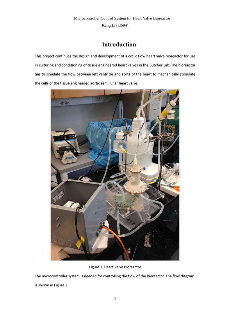
Introduction
This project continues the design and development of a cyclic flow heart valve bioreactor for use
in culturing and conditioning of tissue engineered heart valves in the Butcher Lab. The bioreactor
has to simulate the flow between left ventricle and aorta of the heart to mechanically stimulate
the cells of the tissue engineered aortic semi lunar heart valve.
Figure 1. Heart Valve Bioreactor
The microcontroller system is needed for controlling the flow of the bioreactor. The flow diagram
is shown in Figure 2.
Microcontroller Control System for Heart Valve Bioreactor
Kang Li (kl694)
2
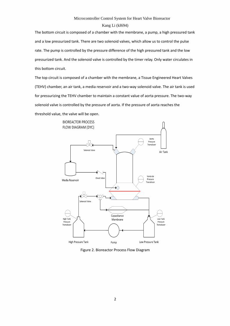
The bottom circuit is composed of a chamber with the membrane, a pump, a high pressured tank
and a low pressurized tank. There are two solenoid valves, which allow us to control the pulse
rate. The pump is controlled by the pressure difference of the high pressured tank and the low
pressurized tank. And the solenoid valve is controlled by the timer relay. Only water circulates in
this bottom circuit.
The top circuit is composed of a chamber with the membrane, a Tissue Engineered Heart Valves
(TEHV) chamber, an air tank, a media reservoir and a two-way solenoid valve. The air tank is used
for pressurizing the TEHV chamber to maintain a constant value of aorta pressure. The two-way
solenoid valve is controlled by the pressure of aorta. If the pressure of aorta reaches the
threshold value, the valve will be open.
Figure 2. Bioreactor Process Flow Diagram

Microcontroller Control System for Heart Valve Bioreactor
Kang Li (kl694)
3
Figure 3. Example of Pump and Solenoid Valve control procedure
We can see one example of pump and solenoid valve control procedure in Figure 3. The pump is
turned on/off based on the pressure difference between high tank and low tank: if the pressure
difference exceeds the upper threshold, the pump will stop working; if the pressure difference is
smaller than the lower threshold, the pump will start working. The two-way solenoid valve is
controlled based on the pressure of aorta. If the pressure of aorta exceeds the threshold, the
valve will be open; otherwise it will be closed.

Microcontroller Control System for Heart Valve Bioreactor
Kang Li (kl694)
4
High Level Design
I use ATmega 1284P microcontroller in this project. I use the built-in Analog to Digital Converter
to read the signal from the four transducers and control the pump based on the pressure
difference of high tank and low tank and control the two-way solenoid valve based on the
pressure of aorta. I also use MATLAB to communicate the microcontroller with the PC. I collect
data and plot real-time waveforms using MATLAB. I also use TRT (Tiny Real Time) to implement
multitasking on the microcontroller. The High Level Design diagram is shown in Figure 3.
There are several variables I need to change or monitor in this project. Parts of them are
calculated for calibrating the bioreactor by using MATLAB. And the rest of the variables are set
every time we want to change the state of the bioreactor. They are as follows:
Name Description Need to change?
P_diff This is the pressure difference between high tank and low tank,
which is used for controlling the pump.
Y
dP_MA Moving Average of the pressure. This parameter and “delta” help
P_diff to determine the upper and lower pressure thresholds for
the pump.
N
Bias Pressure bias. This is calculated by the former designer for
eliminating the noise.
N
thres The threshold pressure of the aorta pressure. When the pressure
of aorta pressure reaches this value, the valve will open.
Y
delta This variable is multiplied by dP_MA every time when the
microcontroller compares the pressure difference.
Y
Gain This variable is multiplied by the measured pressure difference by
Microcontroller for comparing the expected P_diff.
N
Table 1. Key variables and the descriptions

Microcontroller Control System for Heart Valve Bioreactor
Kang Li (kl694)
5
Figure 4. High Level Design

Microcontroller Control System for Heart Valve Bioreactor
Kang Li (kl694)
6
Hardware design
Junction Box
I need to use microcontroller to control the pump and solenoid valve, which are both driven by
110V wall AC. But the output of the microcontroller is 5V DC. So I need junction boxes which
contain a relay switch to control the AC circuits.
Figure 5. Junction boxes
The major parts of the junction box include solid state relay, wall switch and wall socket. The
circuit diagram is shown as in Figure 6.
The junction has a power plug which can be put in any wall socket. This plug provide the power of
the junction box. The wall socket and wall switch are on the surface of the junction box. The plug
of the pump or the solenoid can be put in the wall socket. And the wall switch can cut off the AC
circuit in case of emergency situation. In this way, we can energize the pump or the two-way
solenoid valve.
Inside the junction box, the AC live line first goes into one exposed lead of the wall switch. Then it
comes out from the other lead of the wall switch and goes into one exposed lead of the AC
output of the solid state relay. After coming out from the other lead of the AC output of the solid
state relay, the live line connects one of the exposed lead of the wall socket, eventually. And the

Microcontroller Control System for Heart Valve Bioreactor
Kang Li (kl694)
7
neutral line of the power plug directly connects the other exposed lead of the wall socket. And
the ground line of the power plug connects both of the ground lead of the wall switch and the
wall socket. The low-voltage input side of the solid relay switch connects the microcontroller
through a 3.5mm audio cable. So if the microcontroller signal is high (5 volts), the AC output of
the solid state relay conducts. So the load (the pump or the two-way solenoid valve) of the AC
circuit can be energized.
Figure 6. Circuit Diagram of Junction Box
In this way, I keep all the high power circuit inside the junction box so that the system is very safe.
And also the wall switch can cut the circuit off in case of dangerous situation.
Hardware for microcontroller
The outputs of the four transducers are all currents which are in the range of 4-20 mA. But the
built-in ADC of ATmega 1284P can only convert voltage to digital signal. So I put a 250 Ω resistor
in serial with each transducer. The microcontroller measures the voltage drop between the two
MCU Signal MCU GND
Solid State
Relay
Wall AC AC Live
AC Neutral
AC Ground
Junction Box

Microcontroller Control System for Heart Valve Bioreactor
Kang Li (kl694)
8
leads of the resistor.
I need four ADCs in this project. So the GND of the microcontroller should connect one lead of
each resistors and PIN A0 ~ PIN A3 connects the other lead of each resistor. PIN D2 connects the
junction box which controls the pump and PIN C0 connects the junction box which controls the
two-way solenoid valve.
The whole setup is shown in Figure 7.
Figure 7. Hardware setup for Heart Valve Bioreactor

Microcontroller Control System for Heart Valve Bioreactor
Kang Li (kl694)
9
Software design
Microcontroller Part
1. TRT (Tiny Real Time)
I use TRT (Tiny Real Time) to implement the multi-tasking on the microcontroller. TRT is a
real-time kernel which was written by Dan Henriksson and Anton Cervin (technical report). Aso
see the ECE 4760 webpage about TRT. This kernel has some characteristics which make it very
suitable for this project.
Multitask can run on the same ATmega 1284P microcontroller chip.
Every task has its own release and dead time. The scheduling algorithm is Earliest Deadline First
(EDF).
There are semaphores to protect shared resources (e.g. memory, or the UART) which are used by
more than one task.
In this project, I create two task using Tiny Real Time: pump_control and PC_communication. The
task pump_control is reading the signal sending from the four transducers continuously. And it
control the pump based on the pressure difference between high tank and low tank. And it also
controls the two-way solenoid valve based on the pressure of the aorta transducer.
The task PC_communication is reading the serial port. If it receives command sending from the
serial port, it will parse the command and react correspondingly. There are three different
commands based on the first character of the string. They are as follows:
1) “c”: If the first character of the string is “c” (check), which means the PC want to check
the current state of the microcontroller, PC_communication will send back a string which
contains the value of P_diff, dP_MA, delta, Gain, Bias, and threshold of the aorta
pressure transducer. The format is “P_diff%fdP_MA%fdelta%fGain%fBias%fThres%d”.
This string will be parsed in MATLAB.
2) “o”: If the first character of the string is “o” (operation), which means the user wants to
change the value of the key variables, PC_communication will parse the following string
of the command and load the value to the corresponding variables which are used in the
pump_control task.
3) “s”: If the first character of the string is “s” (send), which means the PC is collecting data

Microcontroller Control System for Heart Valve Bioreactor
Kang Li (kl694)
10
and needs the microcontroller to send the data of the four transducers and the pump
signal, PC_communication will package the demanding data into a string and send it back
to PC through serial port. The format of the string is “H%3dL%3dV%3dA%3dU%1d” and it
will be parsed in MATLAB on PC.
These two tasks may access the same variables at the same time. So the TRT will manage these
accesses by using semaphore. The main functions I use in this project is as follows:
Function Description
void trtInitKernel(uint16_t idletask_stack) Sets up the kernel data structures. The
parameter is the desired stack size of the idle
task. For a null idle task, a stack size of 80
should be sufficient.
void trtCreateTask(void (*fun)(void*),
uint16_t stacksize,
uint32_t release, uint32_t deadline, void *args)
Identifies a function to the kernel as a thread.
The parameters specify a pointer to the
function, the desired stack size, the initial
release time, the initial deadline time, and an
arbitrary data input structure. The release time
and deadline must be updated in each task
whenever trtSleepUntil is called. The task
structures are statically allocated. Be sure to
configure MAXNBRTASKS in the kernel file to
be big enough. When created, each task
initializes 35 bytes of storage for registers, but
stack size minimum is around 40 bytes. If any
task stack is too small, the system will crash!
uint32_t trtCurrentTime(void) Get the current global time in timer ticks.
void trtSleepUntil(uint32_t release,
uint32_t deadline)
Puts a task to sleep by making it ineligible to
run until the release time. After the release
time, it will run when it has the nearest
deadline. Never use this function in an ISR. The
(deadline) - (release time) should be greater
than the execution time of the thread between
trtSleepUntil calls so that the kernel can meet
all the deadlines. If you give a slow task a
release time equal to its deadline, then it has
to execute in zero time to meet deadline, and
nothing else can run until the slow task
completes.
void trtCreateSemaphore(uint8_t semnumber,
uint8_t initval)
Creates a semaphore with identifier
semnumber and initval initial value. Be sure to
Microcontroller Control System for Heart Valve Bioreactor
Kang Li (kl694)
11
configure MAXNBRSEMAPHORES in the kernel
file to be big enough. The identifier number is
1-based, so the first semaphore you define
should be numbered 1.
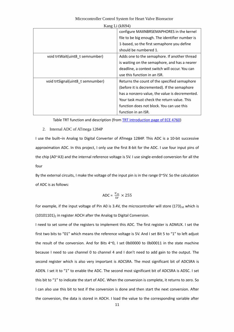
void trtWait(uint8_t semnumber) Adds one to the semaphore. If another thread
is waiting on the semaphore, and has a nearer
deadline, a context switch will occur. You can
use this function in an ISR.
void trtSignal(uint8_t semnumber) Returns the count of the specified semaphore
(before it is decremented). If the semaphore
has a nonzero value, the value is decremented.
Your task must check the return value. This
function does not block. You can use this
function in an ISR.
Table TRT function and description (from TRT introduction page of ECE 4760)
2. Internal ADC of ATmega 1284P
I use the built–in Analog to Digital Converter of ATmega 1284P. This ADC is a 10-bit successive
approximation ADC. In this project, I only use the first 8-bit for the ADC. I use four input pins of
the chip (A0~A3) and the internal reference voltage is 5V. I use single-ended conversion for all the
four
By the external circuits, I make the voltage of the input pin is in the range 0~5V. So the calculation
of ADC is as follows:
ADC = 𝑉𝑖𝑛
5𝑉 × 255
For example, if the input voltage of Pin A0 is 3.4V, the microcontroller will store (173)10 which is
(10101101)2 in register ADCH after the Analog to Digital Conversion.
I need to set some of the registers to implement this ADC. The first register is ADMUX. I set the
first two bits to “01” which means the reference voltage is 5V. And I set Bit 5 to “1” to left adjust
the result of the conversion. And for Bits 4~0, I set 0b00000 to 0b00011 in the state machine
because I need to use channel 0 to channel 4 and I don’t need to add gain to the output. The
second register which is also very important is ADCSRA. The most significant bit of ADCSRA is
ADEN. I set it to “1” to enable the ADC. The second most significant bit of ADCSRA is ADSC. I set
this bit to “1” to indicate the start of ADC. When the conversion is complete, it returns to zero. So
I can also use this bit to test if the conversion is done and then start the next conversion. After
the conversion, the data is stored in ADCH. I load the value to the corresponding variable after

Microcontroller Control System for Heart Valve Bioreactor
Kang Li (kl694)
12
the conversion.
The ADC procedure is implemented in pump_control subroutine. I design a state machine to read
four channels of the ADC and send out the pump control signal. The state machine is as follows:
DIFFERENCE:
In this state, we measure the values of the pressure of high tank and low tank. I use a while-loop
“while (ADCSRA & (1<<ADSC));” to wait for ADC. After this loop, the value in ADCH can be used.
So I load the value to variable P_tank_H which stores the value of high tank pressure. Then I set
the ADC registers as follows:
ADMUX = (1<<REFS0) | (1<<ADLAR) + 0b00001;
ADCSRA |= (1<<ADSC) ;
The first line indicates the channel is changed to channel 1 (Pin A1) and the reference voltage is
5V and the result is left adjusted. The second line starts another ADC procedure.
Then I load the value of ADCH to P_tank_L which stores the pressure of the low tank. After that, I
also need to set the channel to channel 2 (Pin A2). I also set two variables called HighTank_total
and LowTank_total to eliminate the noise of the ADC. I set a count and every time we enter this
state (DIFFERENCE) the count will increment by 1. If the count reaches 50, the microcontroller
will compare the value of HighTank_total and LowTank_total by this sentence: deltaP =
((float)HighTank_total - (float)LowTank_total) / 50 * Gain; (See Table 1 for details).
The value of variable “Gain” is set from the MATLAB and protected by TRT since it is used in two
tasks. After this calculation, I can use deltaP to control the pump. If(deltaP < P_diff - delta *
dP_MA) , we should turn on the pump. The variables “P_diff”, “delta”, and “dP_MA” are also set
from MATLAB and protected by TRT. If(deltaP >= P_diff + delta * dP_MA), we should turn off the
pump.
VENTRICLE:
This state only reads the data of Pin A2. And the microcontroller will load the value of ADCH to
variable “P_ventricle” and change the channel to channel 3 (Pin A3).
AORTA:
This state reads the data of Pin A3. The microcontroller will load the value of ADCH to variable

Microcontroller Control System for Heart Valve Bioreactor
Kang Li (kl694)
13
“P_aorta” and change the channel to channel 0 (Pin A0). And also, the microcontroller will
control the two-way solenoid valve in this state. If P_aorta is bigger than the threshold value
(variable “thres”), the microcontroller will send an open signal to the valve. Otherwise, the
microcontroller will send a close signal. In this state, the microcontroller also put the four variable
in a page whose format is H%3dL%3dV%3dA%3dU%1d. This is used for sending data to MATLAB.
MATLAB Part
I use MATLAB to communicate with the microcontroller and collect data. It is fairly easy to set up
the serial port in MATLAB. The basic steps of the MATLAB code are as follows:
1. Load the calibration parameters of the bioreactor
These parameters which are essential for the bioreactor control were created by the
former students during the calibration time of the whole bioreactor system. They are in
the form of mat file. So we can load them directly.
2. Close all the peripheral of the computer and open the serial port
Before we open the serial port of the computer, we need to make sure all the
instruments are deleted by using “delete(instrfindall);”. Then we can open the serial port
by the command:
fid = serial(“com8”);
fopen(fid);
Otherwise, MATLAB may get the runtime error.
3. Check the current state of the microcontroller
After we open the serial port, we can communicate with the microcontroller through
USB cable. First thing we want to know is what kind of state the microcontroller or the
bioreactor is. So we can send a check signal which is a single character “c” in my design
to the microcontroller. The microcontroller receives the check signal and sends back a
piece of information containing the current state. The format of the information is
“P_diffXXXdP_MAXXXdeltaXXXGainXXXBiasXXXThresXXX”. Then MATLAB parses the
information by using “strfind” function. And finishing parsing this information, MATLAB
will print out the parsed information in the command window. So the user will check the
current state of the whole system (Please check User Manual for screen captures).

Microcontroller Control System for Heart Valve Bioreactor
Kang Li (kl694)
14
4. Set the value of the key variables through user interface and send them to microcontroller
Since we get the information of the state, we might want to change it to satisfy the
demand of this period of data collection. After printing out the state of the
microcontroller, MATLAB will ask the user “Do you want to change the current values?” If
the user types in 0, the state won’t change and the MATLAB starts collecting data; If the
user types in 1, MATLAB will prompt the user to change the state of the system. After
finishing changing the value, MATLAB will print out the value which the user just typed in
and ask the user “Please type in 1 or 0 (1 for correct)”. If the user types in 0, the whole
procedure of changing values will start over again; if the user types in 1, MATLAB will
send the new value to the microcontroller and starts to collect data. The format of the
string which MATLAB sends to the microcontroller is “oPXXXfCXXXDXXXGXXXBXXXTXXX”
and this string will be parsed in microcontroller.
5. Start to collect data and plot the real-time waveform of the four transducers
After changing the value of the key variables, we can collect data now. I use a for-loop to
do the data collection. Instead of letting the microcontroller send data continuously, I
design a simple “handshaking” protocol because MATLAB is very bad at dealing with
memory control and it may flush the memory if we don’t control the data transfer. The
first thing is that MATLAB sends a character “s” to the microcontroller. The
microcontroller recognizes the character and then sends back a string whose format is
“HXXXLXXXVXXXAXXXUX”. This string contains the value of the four transducers (High
tank, Low tank, Ventricle, Aorta) and the pump signal (high or low). MATLAB will parse
the string and send values to the corresponding variable. And then MATLAB plots the
points in the figure. After finishing plotting, MATLAB will send “s” again and start the
whole procedure again until it reaches the length of the time period we set.
In this way, the whole procedure of data collection is under control. Notice that we have
to use pause() function between sending “s” and receiving the string, even when we only
need a really short pause. Otherwise, the real time waveform will stuck and the whole
waveform will appear after we finish collecting data.
6. Save the data of the four transducers for further analysis

Microcontroller Control System for Heart Valve Bioreactor
Kang Li (kl694)
15
The last step is that we save the data to a mat file for further analysis. The data we want
to save is High_tank, Low_tank, Ventricle, and Aorta. And then we delete all the other
internal variables. At last, MATLAB will print a pink information telling the user what
format of the saved data is.
Microcontroller Control System for Heart Valve Bioreactor
Kang Li (kl694)
16
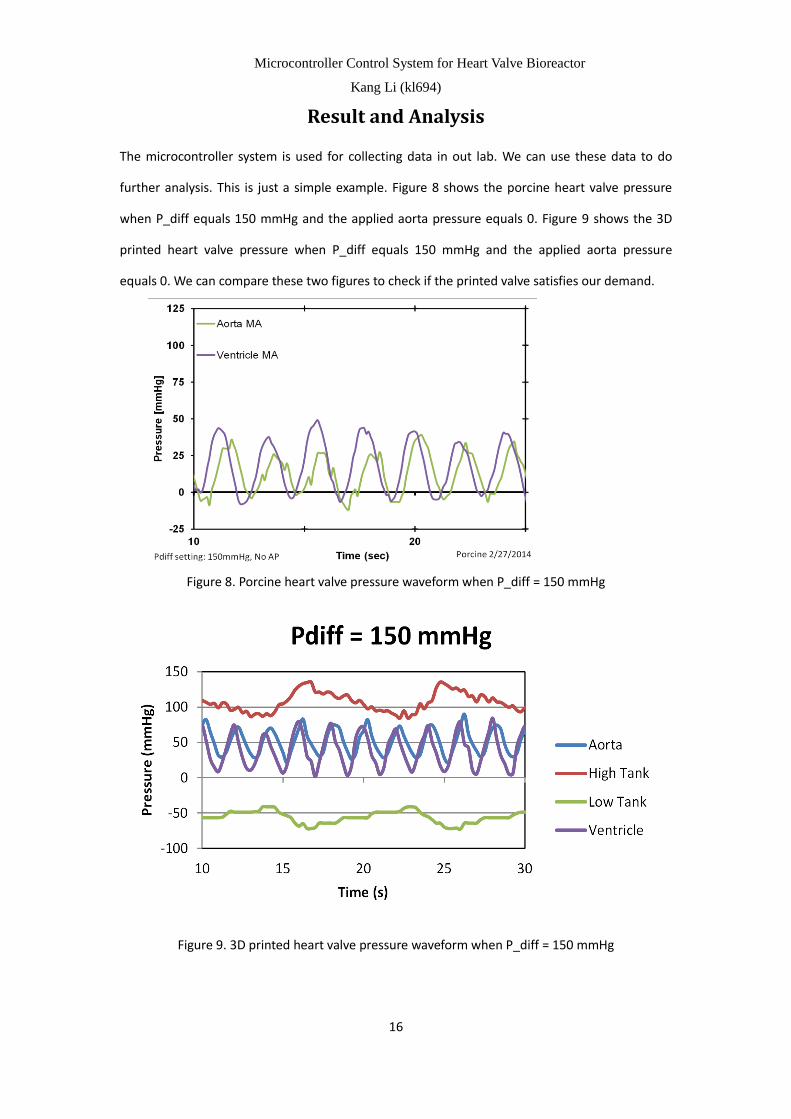
Result and Analysis
The microcontroller system is used for collecting data in out lab. We can use these data to do
further analysis. This is just a simple example. Figure 8 shows the porcine heart valve pressure
when P_diff equals 150 mmHg and the applied aorta pressure equals 0. Figure 9 shows the 3D
printed heart valve pressure when P_diff equals 150 mmHg and the applied aorta pressure
equals 0. We can compare these two figures to check if the printed valve satisfies our demand.
Figure 8. Porcine heart valve pressure waveform when P_diff = 150 mmHg
Figure 9. 3D printed heart valve pressure waveform when P_diff = 150 mmHg

Microcontroller Control System for Heart Valve Bioreactor
Kang Li (kl694)
17
Conclusion
I designed a microcontroller control system for the heart valve bioreactor. It can control the flow
of the whole system based on the specified parameters and collect data in MATLAB.
The future work could be that we can design our own prototype board instead of using bread
board so the whole system could be more compact. And also, we can build several parallel TEHV
chambers instead of just one.
Acknowledgement
I would like to thank my advisor Bruce Land for all his instruction. His advice of junction box really
make the project much safer. And he taught me how to change the clock frequency to make the
TRT run for much longer time. All these things make the project much easier for me to
accomplish.
And I also want to thank all the team members in our bio-print team, especially Laura. She is
always so patient and kind. When I started to participate in this project, I know nothing about the
machenism of heart valve and the bioreactor. She told me how to start and what goal we should
achieve. When I have questions, she always explains to me no matter how stupid the question is.
And also for Alain, Dan, and Duan, you guys are always helping me when I have problems.

Microcontroller Control System for Heart Valve Bioreactor
Kang Li (kl694)
18
APPENDIX A
User Manual
1. Hardware setup
Currently, I put all the wire connections on the bread board so all the circuit should be
set up as in Figure. And then we should connect the microcontroller and the PC through
USB cable.
2. Run MATLAB code
Before we run the MATLAB code, we should check “Device Manager” to see which serial
port we are using to connect the microcontroller. Then we should go to the fifth line of
the MATLAB scripts and change “com8” to the serial port we are using.
After that, we can run our MATLAB code. The first thing we can see is the time length of
this experiment, as shown in Figure 10.
Figure 10. Prompt line of time length
We should type in how long we want to collect data. Notice that the user must type in an
integer in this procedure.
Then the MATLAB will send the current state of the whole system, as shown in Figure 11.

Microcontroller Control System for Heart Valve Bioreactor
Kang Li (kl694)
19
Figure 11. The current state of the whole system
These information is sent back from the microcontroller. If we want to change the state,
we should type in “1”; otherwise we should type in “0”. After we type in “1”, the MATLAB
will guide us to change the values of some key variables, as shown in Figure 12.
Figure 12. Change the values of key variables
After we check the desired value of the key variables, we should type in “1” if all the

Microcontroller Control System for Heart Valve Bioreactor
Kang Li (kl694)
20
values are correct; otherwise we should type in “0” and start the whole procedure over
again.
After we determine the value of the key parameters, MATLAB will start to collect data.
MATLAB will plot the real-time waveforms of the four transducers, as shown in Figure 13.
Figure 13. Real-time Waveforms of four transducers
We can monitor the pressures by these real-time waveforms.
After we reached the time length of this experiment, MATLAB will store the four vectors
of the values of the four pressures in a mat file and prompt a pink line to tell the user
what format of the saved data is, as shown in Figure 14.
Figure 14. File format
In this way, we can guarantee that there will never be two files which have the same
name and we can use the data to do further analysis.
Microcontroller Control System for Heart Valve Bioreactor
Kang Li (kl694)
21
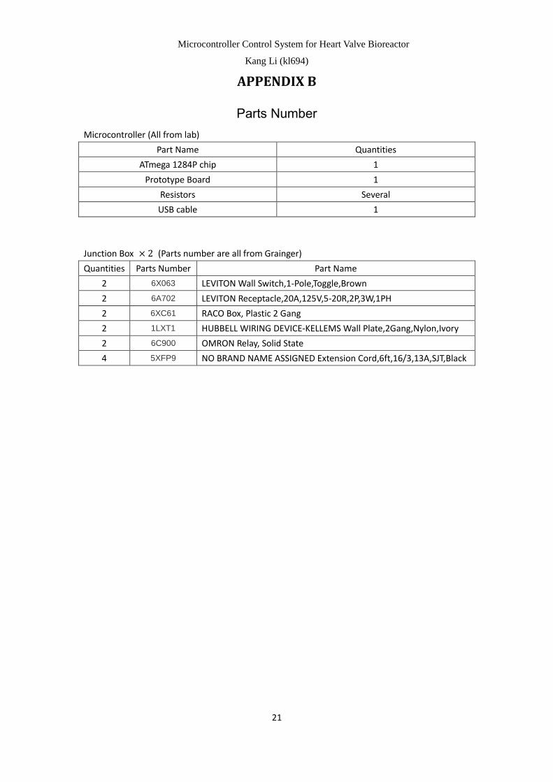
APPENDIX B
Parts Number
Microcontroller (All from lab)
Part Name Quantities
ATmega 1284P chip 1
Prototype Board 1
Resistors Several
USB cable 1
Junction Box × 2 (Parts number are all from Grainger)
Quantities Parts Number Part Name
2 6X063 LEVITON Wall Switch,1-Pole,Toggle,Brown
2 6A702 LEVITON Receptacle,20A,125V,5-20R,2P,3W,1PH
2 6XC61 RACO Box, Plastic 2 Gang
2 1LXT1 HUBBELL WIRING DEVICE-KELLEMS Wall Plate,2Gang,Nylon,Ivory
2 6C900 OMRON Relay, Solid State
4 5XFP9 NO BRAND NAME ASSIGNED Extension Cord,6ft,16/3,13A,SJT,Black

Microcontroller Control System for Heart Valve Bioreactor
Kang Li (kl694)
22
APPENDIX C
Source Code
pump_trt_28.c
/*-------------------------------------------------------------*/
/*This script is written for MENG Project: Heart Valve Bioreactor
by Kang Li (kl694), Cornell University*/
#define F_CPU 16000000UL
#include "trtSettings.h"
#include "trtkernel_1284.c"
#include <avr/interrupt.h>
#include <avr/pgmspace.h>
#include <stdio.h>
#include <stdlib.h>
#include <string.h>
#include <avr/sleep.h>
#define begin {
#define end }
// serial communication library
// Don't mess with the semaphores
#define SEM_RX_ISR_SIGNAL 1
#define SEM_STRING_DONE 2 // user hit <enter>
#include "trtUart.h"
#include "trtUart.c"
#define DIFFERENCE 11
#define AORTA 12
#define VENTRICLE 13
#define READ(U, N) ((U) >> (N) & 1u)
#define SET(U, N) ((void)((U) |= 1u << (N)))
#define CLR(U, N) ((void)((U) &= ~(1u << (N))))
#define FLIP(U, N) ((void)((U) ^= 1u << (N)))
#define SEM_SEND 3
#define SEM_INPUT 4
#define SEM_SQUARE 5
#define T_OVERFLOW 500
// UART file descriptor

Microcontroller Control System for Heart Valve Bioreactor
Kang Li (kl694)
23
// putchar and getchar are in uart.c
FILE uart_str = FDEV_SETUP_STREAM(uart_putchar, uart_getchar, _FDEV_SETUP_RW);
int args[2];
unsigned char P_tank_H, P_tank_L;
double P_diff;
int count;
double deltaP;
double delta;
double time_squarewave, dP_MA, Gain, Bias;
int thres,T;
float P, C, D, G, B;
unsigned char P_aorta, P_ventricle;
unsigned char channel_flag ;
long HighTank_total, LowTank_total;
int pumpSignal;
char sendData[14];
void initialize(void);
int main(void)
begin
initialize();
set_sleep_mode(SLEEP_MODE_IDLE);
sleep_enable();
while (1)
begin
CLR(PORTD,1);
sleep_cpu();
end
end
void pump_control(void * args)
begin
uint32_t rel,dead;
while(1)
begin
switch(channel_flag)
begin
case (DIFFERENCE):
// wait for ADC done
while (ADCSRA & (1<<ADSC));

Microcontroller Control System for Heart Valve Bioreactor
Kang Li (kl694)
24
P_tank_H = ADCH;
ADMUX = (1<<REFS0) | (1<<ADLAR) + 0b00001;
ADCSRA |= (1<<ADSC) ;
HighTank_total += P_tank_H;
// wait for ADC done
while (ADCSRA & (1<<ADSC));
P_tank_L = ADCH;
//Reference voltage is 5V; Write one to ADLAR to left adjust the result; Select
the PINA1(ADC1) as analog input
ADMUX = (1<<REFS0) | (1<<ADLAR) + 0b00010;
ADCSRA |= (1<<ADSC) ;
LowTank_total += P_tank_L;
count++;
if (count >= 50)
begin
count = 0;
trtWait(SEM_INPUT);
deltaP = ((float)HighTank_total - (float)LowTank_total) / 50 * Gain;
trtSignal(SEM_INPUT);
HighTank_total = 0;
LowTank_total = 0;
//load the values sent from MATLAB and protect the variables using TRT
trtWait(SEM_INPUT);
P_diff = P;
dP_MA = C;
delta = D;
Gain = G;
Bias = B;
thres = T;
trtSignal(SEM_INPUT);
//if P_diff, dP_MA, delta are all zeros, don't start the pump
if((P_diff > 0) || (dP_MA > 0) || (delta > 0))
begin
if(deltaP < P_diff - delta * dP_MA)
begin
SET(PORTD, 2); // turn on the pump
trtWait(SEM_SEND);
pumpSignal = 1;
trtSignal(SEM_SEND);
end
if(deltaP >= P_diff + delta * dP_MA)

Microcontroller Control System for Heart Valve Bioreactor
Kang Li (kl694)
25
begin
CLR(PORTD, 2); // turn off the pump
trtWait(SEM_SEND);
pumpSignal = 0;
trtSignal(SEM_SEND);
end
end
else
begin
CLR(PORTD, 2);
end
end
channel_flag = VENTRICLE;
break;
case (VENTRICLE):
// wait for ADC done
while (ADCSRA & (1<<ADSC));
P_ventricle = ADCH;
//Reference voltage is 5V; Write one to ADLAR to left adjust the result; Select
the PINA3(ADC3) as analog input
ADMUX = (1<<REFS0) | (1<<ADLAR) + 0b00011;
ADCSRA |= (1<<ADSC) ;
channel_flag = AORTA;
break;
case (AORTA):
while (ADCSRA & (1<<ADSC));
P_aorta = ADCH;;
if(P_aorta >= thres)
begin
CLR(PORTC,0); // open the two-way solenoid valve
end
else
begin
SET(PORTC,0); // close the two-way solenoid vale (the valve is closed
when energized)
end
//Reference voltage is 5V; Write one to ADLAR to left adjust the result; Select
the PINA0(ADC0) as analog input
ADMUX = (1<<REFS0) | (1<<ADLAR) + 0b00000;

Microcontroller Control System for Heart Valve Bioreactor
Kang Li (kl694)
26
ADCSRA |= (1<<ADSC) ;
trtWait(SEM_SEND);
// put the four variables in a package
sprintf(sendData, "H%3dL%3dV%3dA%3dU%1d",P_tank_H,P_tank_L,
P_ventricle, P_aorta, pumpSignal);
trtSignal(SEM_SEND);
channel_flag = DIFFERENCE;
break;
end
rel = trtCurrentTime() + SECONDS2TICKS(0.01);
dead = trtCurrentTime() + SECONDS2TICKS(0.011);
trtSleepUntil(rel, dead);
end
end
void PC_communication(void * args)
begin
char cmd[40], P_str[10], C_str[10], D_str[10], G_str[10], B_str[10], T_str[10];
int p, c, d, g, b, t;
while(1)
begin
fscanf(stdin, "%s", cmd) ;
if (cmd[0] == 'o') // change the value of the protected variables
begin
// parse the received string
p = strchr(cmd,'P')-cmd;
c = strchr(cmd,'C')-cmd;
d = strchr(cmd,'D')-cmd;
g = strchr(cmd,'G')-cmd;
b = strchr(cmd,'B')-cmd;
t = strchr(cmd,'T')-cmd;
strlcpy(P_str, cmd + p + 1, c - p);
strlcpy(C_str, cmd + c + 1, d - c);
strlcpy(D_str, cmd + d + 1, g - d);
strlcpy(G_str, cmd + g + 1, b - g);
strlcpy(B_str, cmd + b + 1, t - b);
strlcpy(T_str, cmd + t + 1, strlen(cmd) - t);
Microcontroller Control System for Heart Valve Bioreactor
Kang Li (kl694)
27
trtWait(SEM_INPUT);
//load the values to corresponding variables
sscanf(P_str, "%f", &P);
sscanf(C_str, "%f", &C);
sscanf(D_str, "%f", &D);
sscanf(G_str, "%f", &G);
sscanf(B_str, "%f", &B);
sscanf(T_str, "%d", &T);
trtSignal(SEM_INPUT);
end
if (cmd[0] == 's') // send the package to PC
begin
trtWait(SEM_SEND);
fprintf(stdout, "%s", sendData);
trtSignal(SEM_SEND) ;
end
if (cmd[0] == 'c') // check the current state of the whole system
begin
trtWait(SEM_INPUT);
fprintf(stdout, "\rP_diff%fdP_MA%fdelta%fGain%fBias%fThres%d\n", P_diff,
dP_MA, delta, Gain, Bias, thres);
trtSignal(SEM_INPUT);
end
end
end
void initialize(void)
begin
CLKPR = (1 << CLKPCE);
CLKPR = (1 << CLKPS0) | (1 << CLKPS1); // set divide by 8
//PINA is input
DDRA = 0x00;
PORTA = 0x00;
//PIND is output
DDRD = 0xff;
PORTD = 0x00;
//PINC is output
DDRC = 0xff;
PORTC = 0x00;
ADMUX = (1<<REFS0) | (1<<ADLAR) + 0b00000;

Microcontroller Control System for Heart Valve Bioreactor
Kang Li (kl694)
28
ADCSRA = (1<<ADEN) | (1<<ADSC) + 7 ;
channel_flag = DIFFERENCE;
P_tank_H = 0;
P_tank_L = 0;
P_aorta = 0;
P_ventricle = 0;
P_diff = 0;
delta = 0;
dP_MA = 0;
Gain = 0;
Bias = 0;
time_squarewave = 0;
thres = 0;
count = 0;
T=0;
//ini uart
trt_uart_init();
stdout = stdin = stderr = &uart_str;
trtInitKernel(300);
trtCreateSemaphore(SEM_RX_ISR_SIGNAL, 0) ; // uart receive ISR semaphore
trtCreateSemaphore(SEM_STRING_DONE,0) ; // user typed <enter>
trtCreateSemaphore(SEM_SEND, 1) ;
trtCreateSemaphore(SEM_INPUT, 1) ;
trtCreateSemaphore(SEM_SQUARE, 1) ;
trtCreateTask(PC_communication, 300, SECONDS2TICKS(0.15), SECONDS2TICKS(0.25),
&(args[0]));
trtCreateTask(pump_control, 300, SECONDS2TICKS(0.01), SECONDS2TICKS(0.015),
&(args[1]));
sei();
end

Microcontroller Control System for Heart Valve Bioreactor
Kang Li (kl694)
29
Heart_valve-MCU.m
clc;clear; % clean the screen and workspace
load CalibTransducer.mat; % load the calibration parameters
close all; % close all the figures
delete(instrfindall); % delete all the instruments
fid = serial('com8'); % open serial port
s.BytesAvailableFcnMode = 'byte'; % set the parameters of the serial port
s.InputBufferSize = 5000;
s.BytesAvailableFcnCount = 10;
s.BaudRate = 9600;
s.BytesAvailableFcn = @my_callback;
s.Timeout = 3000;
fopen(fid);
fprintf('Please type in the time length of this data collection\n'); % prompt the user to type in the
data length
timeout = input('Time length in minutes: ');
timeout_used = timeout * 60 ; % convert minutes to seconds
fprintf(fid,'c\n');
check = [];
scaler = 5/255* 393.3217; %convert the units to mmHg
sample_rate = 44; % samples/second
while ((isempty(check)) || (check(1) ~= 'P')) % check the current state of the whole system
check = fscanf(fid, '%s');
P_diff_location = strfind(check, 'P_diff'); % parse the string
dP_MA_location = strfind(check, 'dP_MA');
delta_location = strfind(check, 'delta');
Gain_location = strfind(check, 'Gain');
Bias_location = strfind(check, 'Bias');
Thres_location = strfind(check, 'Thres');
P_diff_current = str2double(check((P_diff_location + 6):(dP_MA_location - 1)));
dP_MA_current = str2double(check((dP_MA_location + 5):(delta_location - 1)));
delta_current = str2double(check((delta_location + 5):(Gain_location - 1)));
Gain_current = str2double(check((Gain_location + 4):(Bias_location - 1)));
Bias_current = str2double(check((Bias_location + 4):(Thres_location - 1)));
Thres_current = str2double(check((Thres_location + 5):length(check))) * scaler - 388.2081;
end
fprintf('\nThe current values of P_diff, dP_MA, delta, Gain,and Bias are as follows:'); % display the
current state
fprintf('\n\t\t\t\tP_diff = %f', P_diff_current);
fprintf('\n\t\t\t\tdP_MA = %f', dP_MA_current);
fprintf('\n\t\t\t\tdelta = %f', delta_current);
fprintf('\n\t\t\t\tGain = %f', Gain_current);
fprintf('\n\t\t\t\tBias = %f', Bias_current);
fprintf('\n\t\t\t\tThreshold Aorta Pressure = %f', Thres_current );

Microcontroller Control System for Heart Valve Bioreactor
Kang Li (kl694)
30
fprintf('\n*****************************************************************\n\r');
fprintf('\rDo you want to change the current values?\n') % ask the user to change value
check_flag = input('Please input 1 or 0 (1 for changing values)');
if(check_flag ~= 0)
finish_input_flag = 0;
while(finish_input_flag == 0)
fprintf('\nPlease input the value of P_diff (the default value is 100)\n');
P_diff = input('P_diff = ');
if (size(P_diff) == 0)
P_diff_used = 100;
else
P_diff_used = P_diff;
end
fprintf('\nPlease input the value of delta (the default value is 1)\n');
delta = input('delta = ');
if (size(delta) == 0)
delta_used = 1 ;
else
delta_used = delta;
end
fprintf('\nPlease input the value of the threshold aorta pressure (the default prssure =
77.5723989 mmHg)\n');
thres = input('thres = ');
if (size(thres) == 0)
Thres_used = 77.5723989 ;
else
Thres_used = thres;
end
fprintf('P_diff = %f, delta = %f, threshold aorta voltage = %f\nIs this correct?\n', ...
P_diff_used, delta_used, Thres_used );
finish_input_flag = input('Please input 1 or 0 (1 for correct)\n');
if ((finish_input_flag ~= 0))
clear delta P_diff finish_input_flag thres;
break;
end
end
else
P_diff_used = P_diff_current;
delta_used = delta_current;
Thres_used = Thres_current;
Microcontroller Control System for Heart Valve Bioreactor
Kang Li (kl694)
31
end
R_Use = 250;
Gain_total = a_Transducer * R_Calib / R_Use * 5 /255;
Bias_used = b_Transducer;
Thres_convert = round((Thres_used + 388.2081) / 393.3217 * 255 / 5);
send_packet = sprintf('P%06.2fC%06.3fD%dG%06.3fB%06.3fT%d', P_diff_used, dP_MA,
delta_used, Gain_total, Bias_used, Thres_convert);
fprintf(fid,'o%s\r', send_packet); % send the new value to microcontroller
clear P_diff_current dP_MA_current delta_current %clear the internal variables
clear Gain_current Bias_current
clear P_diff_location dP_MA_location delta_location
clear Gain_location Bias_location Thres_current
%initialize the vectors%initialize the vectors
Low_tank = zeros(timeout_used * sample_rate, 1);
High_tank = zeros(timeout_used * sample_rate, 1);
Ventricle = zeros(timeout_used * sample_rate, 1);
Aorta = zeros(timeout_used * sample_rate, 1);
PumpSignal = zeros(timeout_used * sample_rate, 1);
i_real = 1;
% set the figure handles
figureHandle1 = figure('NumberTitle','off',...
'Name','High Tank Pressure',...
'Color',[0 0 0],'Visible','on');
axesHandle1 = axes('Parent',figureHandle1,...
'YGrid','on',...
'YColor',[0.9725 0.9725 0.9725],...
'XGrid','on',...
'XColor',[0.9725 0.9725 0.9725],...
'Color',[0 0 0],'xlim', [0, timeout_used], 'ylim', [0, 120] * scaler-388.2081);
hold on;
plotHandle1 =
plot(axesHandle1,i_real,High_tank(1,1),'g',i_real,PumpSignal(1,1),'r','Marker','.','LineWidth',1);
xlabel('Time in seconds','FontWeight','bold','FontSize',10,'Color',[1 1 0]);
ylabel('High Tank Pressure in mmHg','FontWeight','bold','FontSize',10,'Color',[1 1 0]);
title('High Tank Pressure','FontSize',15,'Color',[1 1 0]);
figureHandle2 = figure('NumberTitle','off',...
'Name','Low Tank Pressure',...
'Color',[0 0 0],'Visible','on');
axesHandle2 = axes('Parent',figureHandle2,...
'YGrid','on',...
'YColor',[0.9725 0.9725 0.9725],...

Microcontroller Control System for Heart Valve Bioreactor
Kang Li (kl694)
32
'XGrid','on',...
'XColor',[0.9725 0.9725 0.9725],...
'Color',[0 0 0],'xlim', [0, timeout_used], 'ylim', [0, 120] * scaler-388.2081);
hold on;
plotHandle2 =
plot(axesHandle2,i_real,Low_tank(1,1),'g',i_real,PumpSignal(1,1),'r','Marker','.','LineWidth',1);
xlabel('Time in seconds','FontWeight','bold','FontSize',10,'Color',[1 1 0]);
ylabel('Low Tank Pressure in mmHg','FontWeight','bold','FontSize',10,'Color',[1 1 0]);
title('Low Tank Pressure','FontSize',15,'Color',[1 1 0]);
figureHandle3 = figure('NumberTitle','off',...
'Name','Ventricle Pressure',...
'Color',[0 0 0],'Visible','on');
axesHandle3 = axes('Parent',figureHandle3,...
'YGrid','on',...
'YColor',[0.9725 0.9725 0.9725],...
'XGrid','on',...
'XColor',[0.9725 0.9725 0.9725],...
'Color',[0 0 0],'xlim', [0, timeout_used], 'ylim', [0, 120] * scaler-388.2081);
hold on;
plotHandle3 = plot(axesHandle3,i_real,Ventricle(1,1),'Marker','.','LineWidth',1,'Color',[0 1 0]);
xlabel('Time in seconds','FontWeight','bold','FontSize',10,'Color',[1 1 0]);
ylabel('Ventricle Pressure in mmHg','FontWeight','bold','FontSize',10,'Color',[1 1 0]);
title('Ventricle Pressure','FontSize',15,'Color',[1 1 0]);
figureHandle4 = figure('NumberTitle','off',...
'Name','Aorta Pressure',...
'Color',[0 0 0],'Visible','on');
axesHandle4 = axes('Parent',figureHandle4,...
'YGrid','on',...
'YColor',[0.9725 0.9725 0.9725],...
'XGrid','on',...
'XColor',[0.9725 0.9725 0.9725],...
'Color',[0 0 0],'xlim', [0, timeout_used], 'ylim', [0, 120] * scaler-388.2081);
hold on;
plotHandle4 = plot(axesHandle4,i_real,Ventricle(1,1),'Marker','.','LineWidth',1,'Color',[0 1 0]);
xlabel('Time in seconds','FontWeight','bold','FontSize',10,'Color',[1 1 0]);
ylabel('Aorta Pressure in mmHg','FontWeight','bold','FontSize',10,'Color',[1 1 0]);
title('Aorta Pressure','FontSize',15,'Color',[1 1 0]);
PropName1(1)={'YData'};
PropName1(2)={'Color'};
PropName1(3)={'XData'};

Microcontroller Control System for Heart Valve Bioreactor
Kang Li (kl694)
33
PropName2(1)={'YData'};
PropName2(2)={'Color'};
PropName2(3)={'XData'};
PropVal1(1,2)={[0 1 0]};
PropVal1(2,2)={[0 1 0]};
PropVal2(1,2)={[0 1 0]};
PropVal2(2,2)={[0 1 0]};
% start to collect data and plot the real-time waveform
for i = 2:(timeout_used * sample_rate)
fprintf(fid, '%c\r','s');
pause(0.001);
f_test = fscanf(fid,'%s');
if ((~isempty(f_test)) && (f_test(1) == 'H'))
i_real = i_real + 1;
H = find(f_test == 'H');
L = find(f_test == 'L');
V = find(f_test == 'V');
A = find(f_test == 'A');
U = find(f_test == 'U');
High_tank(i_real,1) = str2double(f_test((H + 1):(L - 1)))*scaler-388.2081;
Low_tank(i_real,1) = str2double(f_test((L + 1):(V - 1)))*scaler-388.2081;
Ventricle(i_real,1) = str2double(f_test((V + 1):(A - 1)))*scaler-388.2081;
Aorta(i_real,1) = str2double(f_test((A + 1):(U - 1)))*scaler-388.2081;
PumpSignal(i_real,1) = str2double(f_test((U + 1):(length(f_test) - 1)))*200;
PropVal1(1,1)={High_tank(1:i_real)};
PropVal1(1,3)={[1:i_real] / sample_rate};
PropVal1(2,1)={PumpSignal(1:i_real)};
PropVal1(2,3)={[1:i_real] / sample_rate};
set(plotHandle1,PropName1,PropVal1);
set(plotHandle2,'YData',Low_tank(1:i_real),'XData',[1:i_real] / sample_rate);
PropVal2(1,1)={Low_tank(1:i_real)};
PropVal2(1,3)={[1:i_real] / sample_rate};
PropVal2(2,1)={PumpSignal(1:i_real)};
PropVal2(2,3)={[1:i_real]/ sample_rate};
set(plotHandle2,PropName2,PropVal2);
set(plotHandle3,'YData',Ventricle(1:i_real),'XData',[1:i_real] / sample_rate);
set(plotHandle4,'YData',Aorta(1:i_real),'XData',[1:i_real] / sample_rate);
end
end

Microcontroller Control System for Heart Valve Bioreactor
Kang Li (kl694)
34
timelength = timeout_used / 60;
% savefile is the name of the saved file
savefile = sprintf('%d_%2d_%2d_%2d_%2d_%d',
year(now),month(now),day(now),hour(now),minute(now),timelength);
cprintf(-[1,0,1],'\n\rThe format of the name of the saved file is
"Year_Month_Day_Hour_Minute_Timelength"\n\r"');
% save the four vectors to a mat file
save(savefile, 'High_tank', 'Low_tank', 'Ventricle', 'Aorta');
%clear all the internal variables
clear f f1 H L A V over timelength timeout_used send_packet t_Average;
clear figureHandle1 figureHandle2 figureHandle3 figureHandle4;
clear plotHandle1 plotHandle2 plotHandle3 plotHandle4;
clear axesHandle1 axesHandle2 axesHandle3 axesHandle4;
clear i i_real check check_flag s savefile timeout f_test;
clear Square_current Square_used Square_location scaler;
clear Bias_used Gain_total P_diff_used PropName1 PropName2 PropVal1 PropVal2
clear R_Calib R_used U a_Transducer b_Transducer dP_MA dV_MA R_Use delta_used
% close the serial port
fclose(fid);
delete(fid);
clear fid