MICRO PRODUCTS COMPANY - Micro · PDF fileMICRO PRODUCTS COMPANY ... switch button is...
22
MICRO PRODUCTS COMPANY MANUFACTURES OF PRECISION WELDING MACHINES MODEL ACMT FINE WIRE BUTT WELDER SERVICE MANUAL 1
Transcript of MICRO PRODUCTS COMPANY - Micro · PDF fileMICRO PRODUCTS COMPANY ... switch button is...

MICRO PRODUCTS COMPANY
MANUFACTURES OF PRECISION WELDING MACHINES
MODEL ACMT FINE WIRE BUTT WELDER
SERVICE MANUAL
1

TABLE OF CONTENTS 1.0 SPECIFICATIONS 2.0 GENERAL OPERATING INSTRUCTIONS 3.0 BASIC OPERATING PARTS 4.0 BASIC OPERATING PARTS LOCATION 5.0 TYPICAL OPERATING SEQUENCE 6.0 SPECIAL ADJUSTMENT 7.0 PREVENTIVE MAINTENANCE 8.0 SUGGESTED SETTINGS 9.0 DIAGNOSTIC CHART FOR TROUBLE SHOOTING 10.0 ELECTRICAL SCHEMATIC 11.0 SAFETY REMINDERS 12.0 BUYERS GUIDE 13.0 PARTS LIST
1.0 SPECIFICATIONS
MODEL ACMT
Stock Size Range .010 in. to .062 in. Diameter .254mm to 1.57mm
Type Material Steel or Aluminum Stock Size Range-Copper .010 in. to .040 in. Diameter
.254mm to 1.02mm Standard Operating Voltages 120 volts Input Power Cycle 60 Cycle Line Demand 5 Amperes @100% Duty Cycle
15 Amperes @10% Duty Cycle Heat Selection Switch Variac Maximum Weld Demand 10 Amperes Single Phase Weld Transformer
0.8 KVA @50% Duty Cycle
Truck Mounted Welder 2 Stationary Casters 2 Swivel Casters
Floor Space 24”(61cm) x 24”(61cm) Overall Height 60”(152cm) Height to Welding Dies 44”(112cm) Welder Weight Approx. 130 LBS (59kgs)
2

MODEL ACMT FEATURES • Welding heat is meter indicated • Anneal heat is meter indicated • Sensitive headpiece • Stock clamps foot or hand activated • Weld heat, variac control • Wire shear, square cut • Fluorescent lamp • Magnifying glass
2.0 GENERAL OPERATING INSTRUCTIONS 2.1 ELECTRICAL HOOK-UP INSTRUCTIONS
First determine that available electrical service in your plant corresponds to the nameplate rating located on welder housing. Electrical wiring to welder must be of sufficient size to deliver full ampere load with no appreciable loss during the weld cycle. The welder will not operate properly if there is more than a 10% variation in the line voltage. In general, the welder should be fused with a slow blow fuse of the 100% duty cycle rating. The minimum power cable size to the welder can be obtained by using this same current rating.
Refer to National Electrical Code and local electrical regulations for adequate power sizes; disconnect methods and fusing guidelines.
Remember line voltages to the welding machine are potentially dangerous should the power cords be damaged or severed. The welding voltages at the welding dies will not harm an operator since they do not exceed 10 volts.
2.2 SAFETY PRECAUTIONS 2.2.1 ELECTRICAL
Maintain electrical cables to welder in good repair. Welders must be grounded and connections securely tightened. Heat switch must not be changed to a new position while a weld cycle is in process. Disconnect electrical service before servicing the welder – high voltages are located within the base of the welder.
3

2.2.2 MECHANICAL
Operator while using welder must wear safety glasses. Keep all safety guards on welders and use properly. Operators must be instructed on the basic operation of unit to prevent injury. Check nameplate rating and keep within material size range for each welder.
2.3 WELDING DIES
The dies and shoes supplied with the welder will handle most size and material types within the range of the welder. For new weld applications consult the factory for special die and shoe sets.
3.0 BASIC OPERATING PARTS 3.1 WELDING HEAT
The welding heat is adjusted by turning the knob on the right hand corner of top panel, and the welding heat that will pass across welding dies when weld is made is indicated by the welding heat meter directly above knob. When knob is turned to the right (clockwise) the voltage is increased. The movement of this knob to the left (counterclockwise) decreases the voltage. CAUTION. Do not force knob at either end of travel for this will result in damage to variable voltage transformer.
3.2 DIE SPACING The welder is capable of welding a variety of wire sizes (capacity shown on nameplate) but for each change in wire diameter a change in space between the dies is needed. This is obtained by rotating index spacing dial located on left of headpiece. Rotation of dial away from operator (counterclockwise) the space is increased. Numbers stamped on edge indicate a definite space. The number 10 (ten) being the largest opening, and number 1 (one) the smallest. In the course of welding the index spacing knob is rotated toward operator until flange on knob comes in contact with operating switch button, and is continued till operating switch button is depressed and weld is made. Spacing operation must therefore be made after each weld.
4

3.3 UPSET PRESSURE
Spring tension setting is obtained by the rotation of the knurled thumbnut located on the left and to the rear of welding head. The spring tension must be changed when size or types of wire to be welded is changed, number 1 (one) being the least tension.
3.4 WELDING DIES
To prevent excessive wear on the die grooves, small wires should be placed in small grooves and larger wires in their respective grooves. The does serve three purposes: to carry the current to the wires being welded, align the two ends of the wire and prevent wire from slipping while the pressure is applied during welding.
3.5 ANNEALING OR TEMPERING DEVICE
The annealing or tempering device is located just above and in the center of the lamp reflector. It consists of a “U” shaped nichrome strip heated by its own transformer. And which is caused to heat by depressing foot pedal all the way. Wires to be welded can be clamped in die grooves by means of raising clamping fingers by hand, or clamping fingers can be raised also by depressing foot pedal a short distance (a further depression on this foot pedal contacts anneal or tempering device switch and causes the nichrome strip to heat).
5
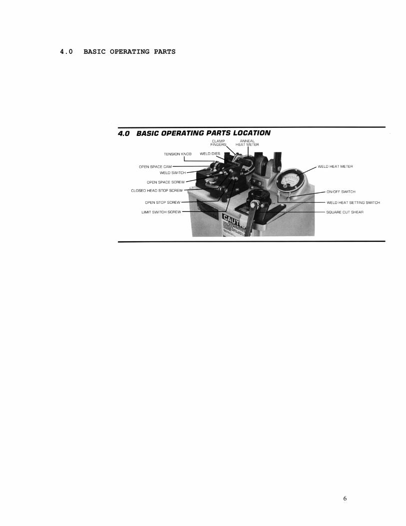
4.0 BASIC OPERATING PARTS
6

5.0 TYPICAL OPERATING SEQUENCE
Wire to be joined must be free of rust, corrosion or other insulating materials, clean wire where it makes contact with welding dies. 1. Adjust weld heat knob to proper setting. 2. Adjust tension-indicating knot to correspond to chart
settings. 3. Rotate space-adjusting cam to correspond to chart
settings. 4. Square cut each end of wire with cutter provided on
unit 5. Place wires in correct welding die groove, so ends
touch midway between open jaws. 6. Move magnifying glass away from weld area to prevent
lens damage. 7. Rotate the index spacing knob toward the operator
until flange on knob contacts and depresses the operating switch.
8. Hold until the weld is completed (less than 2 seconds required.)
9. Release clamp fingers and remove wire. 10. Hard drawn material or high carbon steel will require
an anneal operation, handle carefully prior to anneal to prevent fracturing a brittle weld.
5.1 To anneal the weld, follow these instructions: A. Place and hold welded section in “U” shaped
heating element of annealing device. B. Depress foot pedal all the way down to activate
anneal switch C. Anneal temperature meter located on left hand
control panel, reads directly in degrees Fahrenheit, when reading is multiplied by 100.
NOTE: Do not hold foot pedal down too long or the indicating needle on the meter will pass #18 on the scale and damage the meter.
Trim off upset burr to conform to parent metal diameters.
7

6.1 HEADPIECE CLOSED ADJUSTING SCREW
1. Rotate index spacing cam to #1. 2. Adjust screw A for .001” of clearance between front
edges of welding dies. 3. Tighten locknut into position. 4. Clearance is required to prevent possible electrical
damage. 6.2 HEADPIECE OPEN ADJUSTING SCREW
1. Rotate index spacing cam to #10. 2. Adjust screw B so it contacts headpiece casting and at
the same time the index spacing cam push rod contacts movable headpiece.
3. Should the adjusting screw be in poor adjustment, it is possible the cam could not be positioned at #10.
8

6.3 TENSION CALIBTATING SCREW
1. Rotate tension-adjusting knob E flush with end of adjusting worm.
2. Rotate index spacing cam to #1. 3. Pivot movable headpiece, by hand slightly to right and
release. 4. Movable headpiece should just restore to a rest
position. 5. Adjust calibrating screw C-1 to obtain correct and
initial tension. 6.4 LIMIT SWTICH ADJUSTING SCREW, FOR ACMT ONLY
1. Turn on switch. 2. Place index spacing cam on #2. 3. Push operating switch, only located below index spacing
cam. 4. Weld voltage meter located on top panel may or may not
indicate a voltage. If meter shows a voltage, turn limit switch adjusting screw D until meter just drops off. If meter doe not show a voltage turn adjusting screw D until meter shows a reading and then back off until meter drops off.
9

7.0 PREVENTIVE MAINTENANCE 7.1 AS REQUIRED:
Flashings must be removed from between welding dies and clamp fingers with a brush. If flashings are attached so that they cannot be removed by brushing with a soft wire brush, they may be broken loose with a scraper made of fiber or wood.
7.2 DAILY:
7.2.1 Check condition of welding dies and clamp fingers. Replace
Dies or clamp fingers when they have become so worn that stock does not align or there is slipping of stock in the dies during upset pressure.
7.2.2 Check condition of clamp springs. Replace all broken springs or springs that have taken a set.
7.2.3 Check movable head for excessive wear. Have new slide shafts installed and die seats machined if stock does not line up when placed in die grooves.
7.3 MONTHLY: 7.3.1 Remove welding dies and clean bottom of die surface with
#120 emery cloth. Do this by placing the emery cloth on a flat surface plate and rubbing the dies on it, keeping the surface of the die flat. Wipe die and die seat with a clean cloth and replace, taking care not to touch either contact surface with the hand.
7.3.2 Check anneal dies and replace worn or broken parts. 7.3.3 Check insulating fiber pin on limit switch adjusting screw
for broken or frayed ends. 7.3.4 Check upset tension spring and clamp springs. Replace if
springs have been over-stretched and will not return to normal position.
7.4 QUARTERLY: 7.4.1 Disconnect power to welder. Check contacts on operating
and limit switch. Replace those that are burned. 7.4.2 Check anneal dies and replace worn or broken parts. 7.4.3 Check insulating fiber pin on limit switch adjusting screw
for broken or frayed ends. 7.4.4 Check upset tension spring and clamp springs. Replace if
springs have been over-stretched and will not return to normal position.
10

7.5 ANNUALLY: 7.5.1 Remove the movable headpiece and check condition of slide
shafts. Wash slide shafts with low residue cleaner, lightly oil and replace headpiece.
7.5.2 Check condition of headpiece castings. If worn or broken, replace with new headpiece. If welder is used in an area where there are corrosive fumes, clean off all oxides and paint where possible.
7.6 WELDING DIE INFORMATION
Description: Welding dies – Lower conducting electrode and clamp jaw. Welding clamp fingers – Upper clamping member. WELDING DIES IN POOR CONDITION ARE THE MAIN CAUSES OF BAD WELDS.
7.6.0 CARE OF DIE SETS 7.6.1 Use a Brass or fiber blade to remove particles of flashings
that build-up on die sets. Excessive flash build-up causes die burns on material and shorting of die sets.
7.6.2 Do not attempt to clamp material that is not suited for welder into die sets. Undersize materials will slip and burn die grooves, oversized materials will overstress clamping parts.
7.6.3 Do not use welding die sets for a vise. These parts will not withstand the mechanical abuse.
7.6.4 Whenever welding dies are replaces, clean bottoms of dies and corresponding die seats to a bright and clean condition before bolting them tightly into place. An oxidized surface will insulate the welding dies and reduce effective welding voltage.
7.6.5 Welding die sets will wear with use and must be changed occasionally for good welding results. Keep and adequate supply of replacement parts available. Wire and rod slippage is a problem caused by poor die sets and a major cause of wire breaks.
11

8.0 SUGGESTED SETTINGS
SIZE
MATERIAL
HEAT
TENSION
SPACE
DIE GROOVE
ANNEALING TEMPERTURE
deg. F .010” Steel 8 0 3 Front 1300 .020” Steel 10 0 5 Middle 1300 .030” Steel 12 0.5 7 Middle 1300 .040” Steel 14 1 8 Back 1300 .050” Steel 15 2 10 Back 1300 .060” Steel 16 2 11 Back 1300 .010” AL 2 0 2 Front 425 .020” AL 4 0 3 Front 425 .040” AL 8 1 4 Middle 425 .050” AL 10 1 8 Back 425 .062” AL 12 2 10 Back 425 .010” Al-alloy 2.5 1 2 Front 425 .020” Al-alloy 5 1.25 3 Front 425 .040” Al-alloy 9.5 2.5 4.5 Middle 425 .050” Al-alloy 11 3.5 8 Back 425 .060” Al-alloy 14 4 10 Back 425
NOTE: These settings are approximate and may be varied to suit needs.
IMPORTANT This is important that this machine be handled carefully as rough usage will result in improper alignment of the abutting wire ends. CARE OF MACHINE Keep in mind that this is a precision machine and as such, requires more than ordinary care. It is constructed to be as nearly automatic as possible, with minimum dependence on ability of operators. A few drops of oil applied occasionally will keep bearings in good condition. Adjustment should be made ONLY by those thoroughly familiar with the operating principles of this welder. 8.1 WELDING DIES INFORMATION
Description: Welding dies – Lower conducting electrode and clamp jaw Welding clamp fingers – Upper clamping member Welding dies in poor condition are the main causes of bad welds. Care of die sets: 1. Use a brass or fiber blade to remove particles of
flashings that build-up on die sets. Excessive flash build-up causes die burns on material and shorting of die sets.
2. Do not attempt to clamp material that is not suited for welder into die sets. Undersize materials will slip and burn die grooves, oversized materials will overstress clamping parts.
3. Do not use welding dies seats for a vise. These parts will not withstand the mechanical abuse.
12
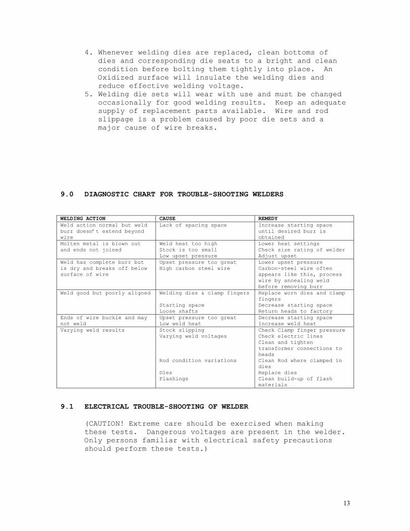
4. Whenever welding dies are replaced, clean bottoms of dies and corresponding die seats to a bright and clean condition before bolting them tightly into place. An Oxidized surface will insulate the welding dies and reduce effective welding voltage.
5. Welding die sets will wear with use and must be changed occasionally for good welding results. Keep an adequate supply of replacement parts available. Wire and rod slippage is a problem caused by poor die sets and a major cause of wire breaks.
9.0 DIAGNOSTIC CHART FOR TROUBLE-SHOOTING WELDERS WELDING ACTION CAUSE REMEDY Weld action normal but weld burr doesn’t extend beyond wire
Lack of spacing space Increase starting space until desired burr is obtained
Molten metal is blown out and ends not joined
Weld heat too high Stock is too small Low upset pressure
Lower heat settings Check size rating of welder Adjust upset
Weld has complete burr but is dry and breaks off below surface of wire
Upset pressure too great High carbon steel wire
Lower upset pressure Carbon-steel wire often appears like this, process wire by annealing weld before removing burr
Weld good but poorly aligned Welding dies & clamp fingers Starting space Loose shafts
Replace worn dies and clamp fingers Decrease starting space Return heads to factory
Ends of wire buckle and may not weld
Upset pressure too great Low weld heat
Decrease starting space Increase weld heat
Varying weld results Stock slipping Varying weld voltages Rod condition variations Dies Flashings
Check Clamp finger pressure Check electric lines Clean and tighten transformer connections to heads Clean Rod where clamped in dies Replace dies Clean build-up of flash materials
9.1 ELECTRICAL TROUBLE-SHOOTING OF WELDER
(CAUTION! Extreme care should be exercised when making these tests. Dangerous voltages are present in the welder. Only persons familiar with electrical safety precautions should perform these tests.)
13

9.1.1 TROUBLE-SHOOTING TABLE (See section 9.1.3) This electrical trouble-shooting table is furnished as a suggested method of trouble-shooting the welder. The individual steps of the table should be performed in the order given, to make the tests valid. The electrical schematic (section 10) furnished for these tests show the table test points. The table may be used for welders with a different but closely related wiring by using corresponding test points. (During all tests, line voltage should be connected to L1 & L2 of the welder. Set the weld rheostat full clockwise.)
9.1.2 FINAL ELECTRICAL CHECKS Set the weld rheostat full clockwise. Connect a voltmeter across the welding dies. Press the operating switch. The meter reading will typically be less than 10 VAC. Consult the weld specification sheet for this value. The weld meter should show full scale. Actuate the weld limit switch; observe the readings go to zero. Release the weld limit and operating switches, the reading should remain at zero.
HOLD THE ANNEAL SWITCH DEPRESSED. The anneal temperature meter will slowly move up scale until full scale is reached. Release the anneal switch, observe that the meter returns to zero after complete cooling of the annealing device. 9.1.3
TEST LEAD CONNECTION
METER
READING
PROBLEM IF NO
READING
PRESS OPERATING SWITCH
WELD LMIT SWITCH
ACTUATED
PRESS ANNEAL SWITCH
L2 S2-2 115VAC Bad on/off switch L2 FU1-1 115VAC Bad fuse connection L2 FU1-2 115VAC Open fuse L2 PB1-1 115VAC Open wire to operating switch L2 PB1-2 115VAC Bad operating switch X L2 LS1-1 115VAC Open connection to weld limit
switch X
L2 LS1-2 115VAC Open weld limit switch X L2 PB2-1 115VAC Open wire to anneal switch L2 PB2-2 115VAC Bad anneal switch X L2 T1-1 115VAC Open wiring to weld transformer X
S1-2 S1-4 115VAC Open wire to heat variac
Note: to perform repair consult section 13 for parts identification.
14

10. ELECTRICAL SCHEMATIC
15

11.0 SAFETY REMINDERS
The following accident prevention information is presented to eliminate potential hazards while operating, inspecting or repairing Micro-Weld Electric resistance welding equipment. Important safety compliance information for Micro-Weld Welders. GENERAL 1. Qualified personnel, prior to using equipment, must
instruct an operator on basic operation and malfunction methods.
2. Safety eyeglasses must be worn by all personnel operating or servicing welders.
3. Use safety equipment properly and keep safety equipment on welders.
4. Determine that both operating voltages and hertz (cycles) of power supply correspond to ratings listed on welder nameplate located on welder housing.
5. Check nameplate ratings and keep within capacities and material categories stated therein.
6. Adjustments or repairs must be made by persons thoroughly familiar with operating principles of welder.
7. Welder must be disconnected from power supply prior to maintenance or repair procedures.
ELECTRICAL 1. Refer to national Electrical Code and local
regulations for adequate electrical wiring to power welder. Do not operate welder with inadequate electrical power supply cords or cable.
2. All welders must be grounded through power supply and welder ground connection terminal securely tightened.
3. All welders must be able to be disconnected from power source either by a double breaking disconnect switch or unplugged by standard rated plugs.
4. All welders must be fused to prevent injury should an electrical malfunction occur. Welders must never be fused for an ampere load that exceeds the ratings stated on welder nameplate. Normally welders are fused using the nameplate rated load; time lag parameters functional to standard fuse allow this specification.
5. Electric power cords to welder must be kept in good condition. Report any damage or potential hazards to maintenance personnel.
6. The weld head selection switch, potentiometer or range selection devices must not be changed to a new position while a weld operation is in process.
16

12.0 BUYERS GUIDE HOW TO ORDER PARTS: You must provide
1. Machine Model 2. Machine Serial Number 3. Voltage Then identify part(s) on part list in section 13 and provide MICRO with the circled number CALL MICRO at A.C. 630-787-9350 Provide MICRO with your company name and purchase order number.
17

13.0 PARTS LIST
18

19

20
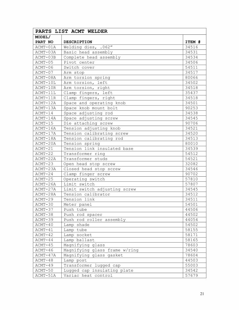
PARTS LIST ACMT WELDER MODEL/ PART NO
DESCRIPTION
ITEM #
ACMT-01A Welding dies, .062” 34516 ACMT-03A Basic head assembly 34531 ACMT-03B Complete head assembly 34534 ACMT-05 Pivot center 34506 ACMT-06 Switch cover 54511 ACMT-07 Arm stop 34517 ACMT-08A Arm torsion spring 80066 ACMT-10L Arm torsion, left 34502 ACMT-10R Arm torsion, right 34518 ACMT-11L Clamp fingers, left 35437 ACMT-11R Clamp fingers, right 34518 ACMT-12A Space and operating knob 34501 ACMT-13A Space knob mount bolt 90253 ACMT-14 Space adjusting rod 34538 ACMT-14A Space adjusting screw 34545 ACMT-15 Die attaching screw 90706 ACMT-16A Tension adjusting knob 34521 ACMT-17A Tension calibrating screw 34520 ACMT-18A Tension calibrating rod 34513 ACMT-20A Tension spring 80010 ACMT-21 Tension link insulated base 34539 ACMT-22 Transformer ring 54512 ACMT-22A Transformer studs 54521 ACMT-23 Open head stop screw 32082 ACMT-23A Closed head stop screw 34546 ACMT-24 Clamp finger screw 90702 ACMT-25 Operating switch 57810 ACMT-26A Limit switch 57807 ACMT-27A Limit switch adjusting screw 34545 ACMT-28A Tension calibrator 34512 ACMT-29 Tension link 34511 ACMT-30 Meter panel 54501 ACMT-37 Push tube 44506 ACMT-38 Push rod spacer 44502 ACMT-39 Push rod roller assembly 44054 ACMT-40 Lamp shade 54502 ACMT-41 Lamp tube 58155 ACMT-42 Lamp socket 58171 ACMT-44 Lamp ballast 58165 ACMT-45 Magnifying glass 78603 ACMT-46 Magnifying glass frame w/ring 34540 ACMT-47A Magnifying glass gasket 78604 ACMT-48 Lamp post 44503 ACMT-49 Transformer lugged cap 55003 ACMT-50 Lugged cap insulating plate 34542 ACMT-51A Variac heat control 57679
21

22
PARTS LIST ACMT WELDER MODEL/ PART NO
DESCRIPTION
ITEM #
ACMT-52 Line switch with on/off plate 57894 ACMT-53A Weld transformer, state voltage and s/n 54520 ACMT-53P Primary for weld transformer 54518 ACMT-53S Secondary weld transformer 54519 ACMT-54A Anneal transformer, state voltage and s/n 54522 ACMT-54P Anneal transformer primary 54523 ACMT-54S Anneal transformer secondary 54524 ACMT-55 Heavy-duty step-down (Micro) transformer,
state voltage and s/n 52519
ACMT-62A Weld heat meter 57753 ACMT-69 Anneal heat meter 57765 ACMT-72 Anneal switch kit (bracket-activator-switch) 44528 ACMT-73 Swivel caster 48100 ACMT-73A Rigid caster 48101 ACMT-74A Heavy-duty shear (E1 type) 64002 ACMT-88 Secondary insulating sleeve 37710 ACMT-90A Lamp switch or meter switch 57838 ACMT-92 Anneal arm attaching bolt 91007 ACMT-93 Lead wire insulating bushing 48407 ACMT-94 High/low range switch 57843 ACMT-100L Anneal arm, left 62028 ACMT-100R Anneal arm, right 62029 ACMT-101 Anneal arm, clamp clevis 62021 ACMT-012 Anneal heater unit 62083 ACMT-103 Anneal insulating block 85230 ACMT-104 Line cord 52521 ACMT-116 Thermocouple lead wire 54530 ACMT-117 Heater unit guard 62027 ACMT-121 Fuse, 5 amp 58103 ACMT-122 Fuse holder 58117 ACMT-123 Terminal board 54510