Micro Motion Model 5700 Transmitters FOUNDATION Fieldbus ... · PDF fileInstallation Manual...
42
Installation Manual MMI-20029969, Rev AA September 2016 Micro Motion ® Model 5700 Transmitters FOUNDATION ™ Fieldbus Installations
Transcript of Micro Motion Model 5700 Transmitters FOUNDATION Fieldbus ... · PDF fileInstallation Manual...

Installation ManualMMI-20029969, Rev AA
September 2016
Micro Motion® Model 5700 Transmitters
FOUNDATION™ Fieldbus Installations
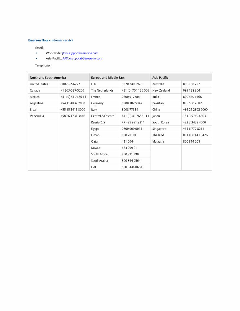
Emerson Flow customer service
Email:
• Worldwide: [email protected]
• Asia-Pacific: [email protected]
Telephone:
North and South America Europe and Middle East Asia Pacific
United States 800-522-6277 U.K. 0870 240 1978 Australia 800 158 727
Canada +1 303-527-5200 The Netherlands +31 (0) 704 136 666 New Zealand 099 128 804
Mexico +41 (0) 41 7686 111 France 0800 917 901 India 800 440 1468
Argentina +54 11 4837 7000 Germany 0800 182 5347 Pakistan 888 550 2682
Brazil +55 15 3413 8000 Italy 8008 77334 China +86 21 2892 9000
Venezuela +58 26 1731 3446 Central & Eastern +41 (0) 41 7686 111 Japan +81 3 5769 6803
Russia/CIS +7 495 981 9811 South Korea +82 2 3438 4600
Egypt 0800 000 0015 Singapore +65 6 777 8211
Oman 800 70101 Thailand 001 800 441 6426
Qatar 431 0044 Malaysia 800 814 008
Kuwait 663 299 01
South Africa 800 991 390
Saudi Arabia 800 844 9564
UAE 800 0444 0684
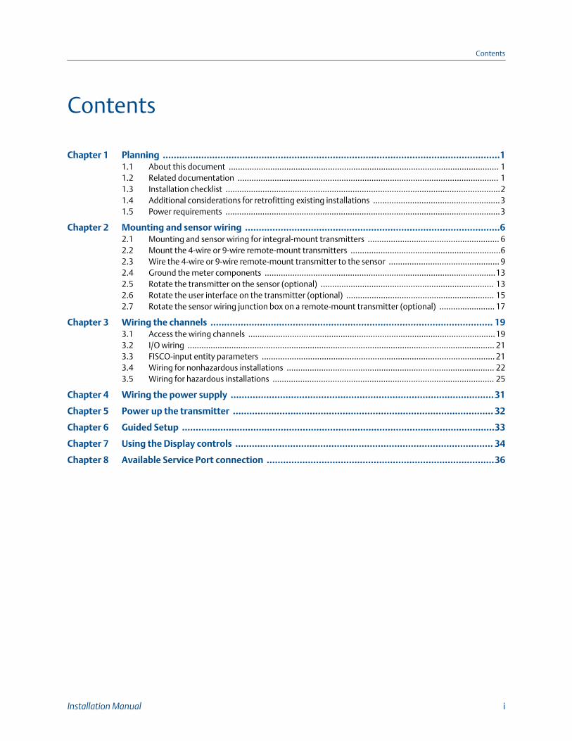
Contents
Chapter 1 Planning ...........................................................................................................................11.1 About this document ..................................................................................................................... 11.2 Related documentation ................................................................................................................. 11.3 Installation checklist .......................................................................................................................21.4 Additional considerations for retrofitting existing installations .......................................................31.5 Power requirements .......................................................................................................................3
Chapter 2 Mounting and sensor wiring .............................................................................................62.1 Mounting and sensor wiring for integral-mount transmitters ......................................................... 62.2 Mount the 4-wire or 9-wire remote-mount transmitters .................................................................62.3 Wire the 4-wire or 9-wire remote-mount transmitter to the sensor ................................................ 92.4 Ground the meter components ....................................................................................................132.5 Rotate the transmitter on the sensor (optional) ........................................................................... 132.6 Rotate the user interface on the transmitter (optional) ................................................................ 152.7 Rotate the sensor wiring junction box on a remote-mount transmitter (optional) ........................ 17
Chapter 3 Wiring the channels ....................................................................................................... 193.1 Access the wiring channels ...........................................................................................................193.2 I/O wiring ..................................................................................................................................... 213.3 FISCO-input entity parameters ..................................................................................................... 213.4 Wiring for nonhazardous installations .......................................................................................... 223.5 Wiring for hazardous installations ................................................................................................ 25
Chapter 4 Wiring the power supply ................................................................................................31
Chapter 5 Power up the transmitter ............................................................................................... 32
Chapter 6 Guided Setup ..................................................................................................................33
Chapter 7 Using the Display controls .............................................................................................. 34
Chapter 8 Available Service Port connection ...................................................................................36
Contents
Installation Manual i

Contents
ii Micro Motion® Model 5700 transmitters for FOUNDATION™ Fieldbus

1 PlanningTopics covered in this chapter:
• About this document
• Related documentation
• Installation checklist
• Additional considerations for retrofitting existing installations
• Power requirements
1.1 About this documentThis manual provides information on planning, mounting, wiring, and initial setup of thetransmitter. For information on full configuration, maintenance, troubleshooting, orservice of the transmitter, see the configuration and use manual.
The information in this document assumes that users understand:
• Basic transmitter and sensor installation, configuration, and maintenance conceptsand procedures
• All corporate, local government, and national government safety standards andrequirements that guard against injuries and death
1.2 Related documentationYou can find all product documentation via the Micro Motion product documentation DVDshipped with the product or at www.micromotion.com.
Additional documentation and resourcesTable 1-1:
Topic Document
Sensor Sensor documentation
Transmitter configuration anduse
Micro Motion Model 5700 Transmitters FOUNDATION™ FieldbusConfiguration and Use Manual
Product Data Sheet Micro Motion Model 5700 Product Data Sheet (PDS)
Modbus configuration Modbus Interface Tool (MIT) — available at www.micromotion.com
Planning
Installation Manual 1
1.3 Installation checklist□ Safety messages are provided throughout this content to protect personnel and
equipment. Read each safety message carefully before proceeding to the next step.
□ If possible, install the transmitter in a location that will prevent direct exposure tosunlight. The environmental limits for the transmitter may be further restricted byhazardous area approvals.
□ If you plan to mount the transmitter in a hazardous area:
- Verify that the transmitter has the appropriate hazardous area approval. Eachtransmitter has a hazardous area approval tag attached to the transmitterhousing.
- Ensure that any cable used between the transmitter and the sensor meets thehazardous area requirements.
- For ATEX/IECEx installations, you must strictly adhere to the safety instructionsdocumented in the ATEX/IECEx approvals documentation available on the MicroMotion Product Documentation DVD shipped with the product or at www.micromotion.com. Be sure to reference this documentation in addition tothe information shown in this guide.
□ Verify that you have the appropriate cable and required cable installation parts foryour installation. For wiring between the transmitter and sensor, verify themaximum cable length does not exceed 1000 ft (300 m.
□ Ensure that you use the following cable for the different connections:
- A certified FOUNDATION™ Fieldbus cable for FOUNDATION Fieldbus terminals
- A twisted-pair instrument cable for all I/O connections
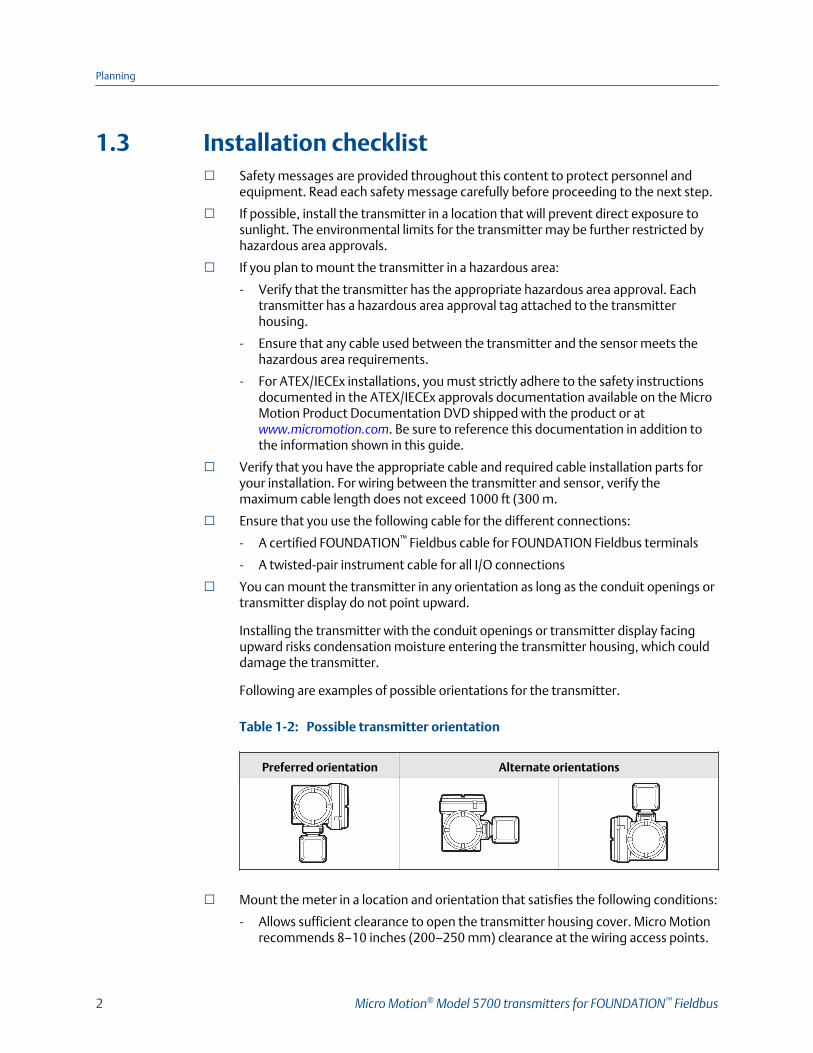
□ You can mount the transmitter in any orientation as long as the conduit openings ortransmitter display do not point upward.
Installing the transmitter with the conduit openings or transmitter display facingupward risks condensation moisture entering the transmitter housing, which coulddamage the transmitter.
Following are examples of possible orientations for the transmitter.
Possible transmitter orientationTable 1-2:
Preferred orientation Alternate orientations
□ Mount the meter in a location and orientation that satisfies the following conditions:
- Allows sufficient clearance to open the transmitter housing cover. Micro Motionrecommends 8–10 inches (200–250 mm) clearance at the wiring access points.
Planning
2 Micro Motion® Model 5700 transmitters for FOUNDATION™ Fieldbus
- Provides clear access for installing cabling to the transmitter.
1.4 Additional considerations for retrofittingexisting installations□ The transmitter installation may require 3–6 inches (76–153 mm) of additional
wiring for the input/output and power connections. This length would be in additionto the currently installed wiring. Confirm you have the additional wiring necessaryfor the new installation.
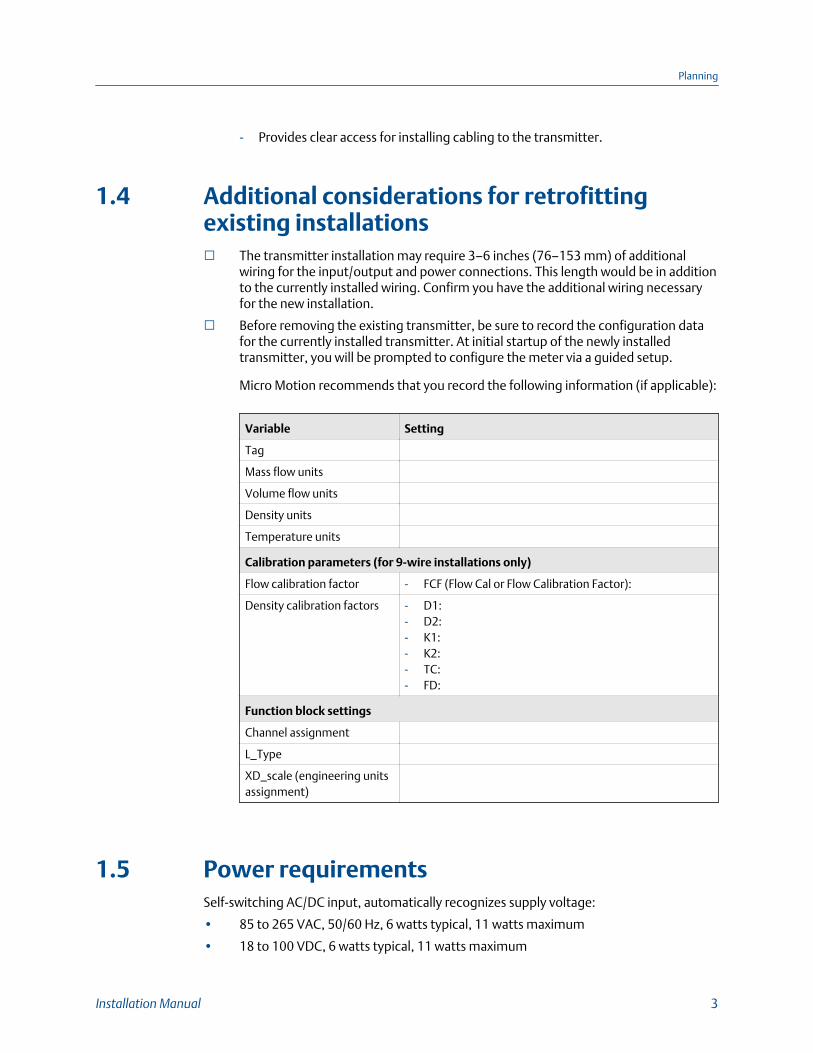
□ Before removing the existing transmitter, be sure to record the configuration datafor the currently installed transmitter. At initial startup of the newly installedtransmitter, you will be prompted to configure the meter via a guided setup.
Micro Motion recommends that you record the following information (if applicable):
Variable Setting
Tag
Mass flow units
Volume flow units
Density units
Temperature units
Calibration parameters (for 9-wire installations only)
Flow calibration factor - FCF (Flow Cal or Flow Calibration Factor):
Density calibration factors - D1:- D2:- K1:- K2:- TC:- FD:
Function block settings
Channel assignment
L_Type
XD_scale (engineering unitsassignment)
1.5 Power requirementsSelf-switching AC/DC input, automatically recognizes supply voltage:
• 85 to 265 VAC, 50/60 Hz, 6 watts typical, 11 watts maximum
• 18 to 100 VDC, 6 watts typical, 11 watts maximum
Planning
Installation Manual 3

NoteFor DC power:
• Power requirements assume a single transmitter per cable.
• At startup, the power source must provide a minimum of 1.5 amps of short-term current pertransmitter.
• Length and conductor diameter of the power cable must be sized to provide 18 VDCminimum at the power terminals, at a load current of 0.7 amps.
Cable sizing formula
M = 18V + (R × L × 0.7A)• M: minimum supply voltage
• R: cable resistance (in Ω/ft)
• L: cable length (in ft)
Typical power cable resistance at 68 °F (20 °C
Wire gauge Resistance
14 AWG 0.0050 Ω/ft
16 AWG 0.0080 Ω/ft
18 AWG 0.0128 Ω/ft
20 AWG 0.0204 Ω/ft
2.5 mm2 0.0136 Ω/m
1.5 mm2 0.0228 Ω/m
1.0 mm2 0.0340 Ω/m
0.75 mm2 0.0460 Ω/m
0.50 mm2 0.0680 Ω/m
1.5.1 Maximum cable lengths between sensor and transmitterThe maximum cable length between the sensor and transmitter that are separatelyinstalled is determined by cable type.
Cable type Wire gauge Maximum length
Micro Motion 4-wire Not applicable • 1000 ft (300 m) without Ex-approval
• 500 ft (150 m) with IIC rat-ed sensors
• 1000 ft (300 m) with IIB rat-ed sensors
Micro Motion 9-wire Not applicable 1000 ft (300 m)
Planning
4 Micro Motion® Model 5700 transmitters for FOUNDATION™ Fieldbus
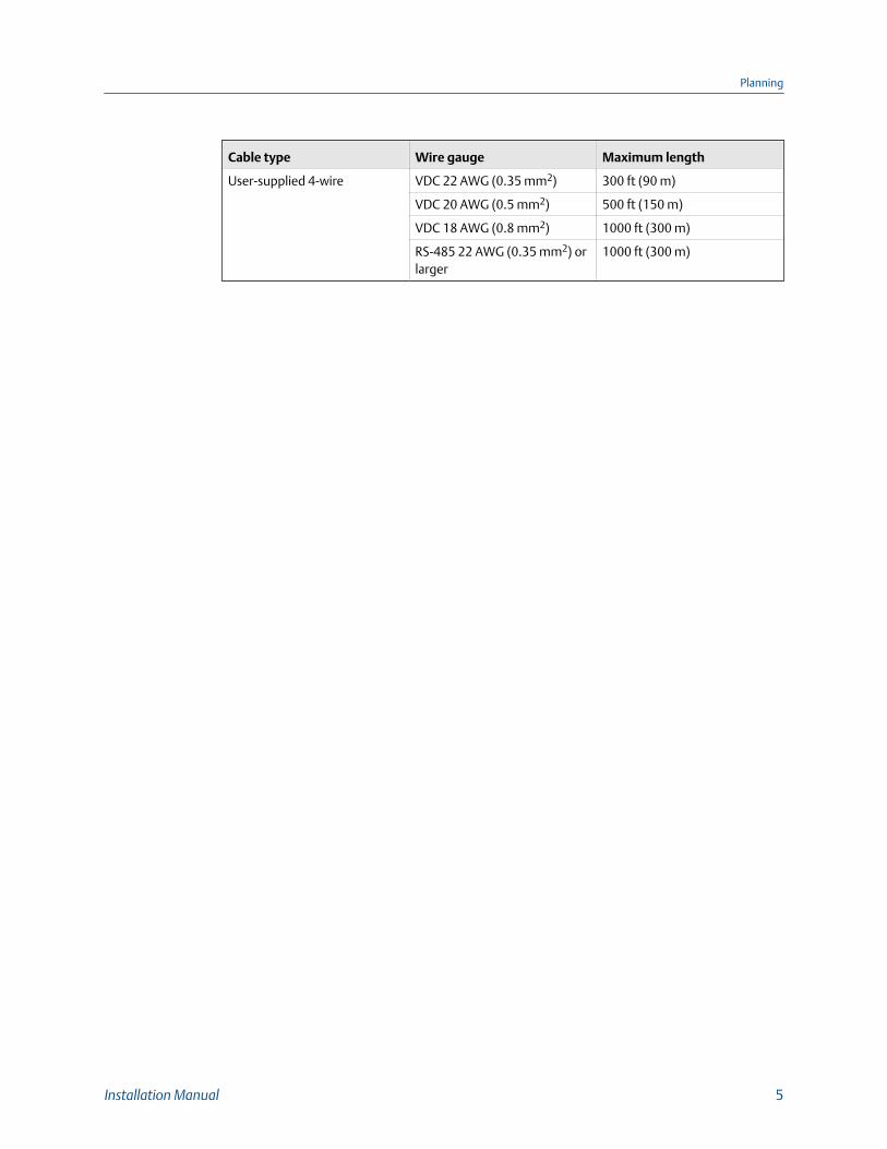
Cable type Wire gauge Maximum length
User-supplied 4-wire VDC 22 AWG (0.35 mm2) 300 ft (90 m)
VDC 20 AWG (0.5 mm2) 500 ft (150 m)
VDC 18 AWG (0.8 mm2) 1000 ft (300 m)
RS-485 22 AWG (0.35 mm2) orlarger
1000 ft (300 m)
Planning
Installation Manual 5
2 Mounting and sensor wiringTopics covered in this chapter:
• Mounting and sensor wiring for integral-mount transmitters
• Mount the 4-wire or 9-wire remote-mount transmitters
• Wire the 4-wire or 9-wire remote-mount transmitter to the sensor
• Ground the meter components
• Rotate the transmitter on the sensor (optional)
• Rotate the user interface on the transmitter (optional)
• Rotate the sensor wiring junction box on a remote-mount transmitter(optional)
2.1 Mounting and sensor wiring for integral-mount transmittersThere are no separate mounting requirements for integral transmitters, and no need toconnect wiring between the transmitter and the sensor.
2.2 Mount the 4-wire or 9-wire remote-mounttransmitters
2.2.1 Mount the transmitter to a wall or instrument poleThere are two options available for mounting the transmitter:
• Mount the transmitter to a wall or flat surface.
• Mount the transmitter to an instrument pole.
Prerequisites
• If you are mounting the transmitter to a wall or flat surface:
- Micro Motion recommends the use of 5/16-18 (8 mm–1.25) fasteners that canwithstand the process environment. Micro Motion does not supply bolts or nutsas part of the standard offering (general purpose bolts and nuts are available asan option).
- Ensure that the surface is flat and rigid, does not vibrate, or move excessively.
- Confirm that you have the necessary tools, and the mounting kit shipped withthe transmitter.
Mounting and sensor wiring
6 Micro Motion® Model 5700 transmitters for FOUNDATION™ Fieldbus

• If you are mounting the transmitter to an instrument pole:
- Ensure that the instrument pole extends at least 12 inches (305 mm) from a rigidbase, and is no more than 2 inches (50.8 mm) in diameter.
- Confirm that you have the necessary tools, and the instrument-pole mountingkit shipped with the transmitter.
Procedure
1. Attach the mounting bracket to the transmitter and tighten the screws to 80-90 in-lbs.
Mounting bracket to transmitterFigure 2-1:
2. Using a wall-mount or pole-mount:
• For wall-mount installations, secure the mounting bracket to the preparedsurface.
Mounting and sensor wiring
Installation Manual 7

Wall-mounting bracket dimensionsFigure 2-2:
A. 2.8 in (71.4 mm)B. 2.8 in (71.4 mm)
• For pole-mount installations, attach the U-bolt mounting piece to theinstrument pole.
Pole-mounting bracket attachmentFigure 2-3:
Mounting and sensor wiring
8 Micro Motion® Model 5700 transmitters for FOUNDATION™ Fieldbus

3. Place and attach the transmitter-mounting bracket to the mounting bracketsecured to the wall or instrument pole.
Attaching and securing transmitter to mounting bracketFigure 2-4:
TipTo ensure the mounting bracket holes are aligned, insert all attachment bolts into place beforetightening.
2.3 Wire the 4-wire or 9-wire remote-mounttransmitter to the sensorPrerequisites
• Prepare 4-wire or 9-wire cable as described in the sensor documentation.
• Connect the cable to the sensor-mounted core processor or junction box asdescribed in the sensor documentation. You can access all product documentationonline via the Micro Motion product documentation DVD shipped with the productor at www.micromotion.com.
Procedure
1. Remove the transmitter-to-sensor wiring compartment cover to reveal the terminalconnections.
Mounting and sensor wiring
Installation Manual 9
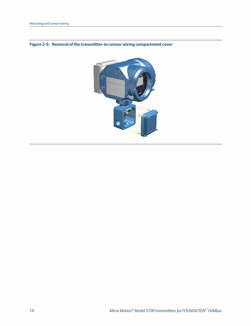
Removal of the transmitter-to-sensor wiring compartment coverFigure 2-5:
Mounting and sensor wiring
10 Micro Motion® Model 5700 transmitters for FOUNDATION™ Fieldbus
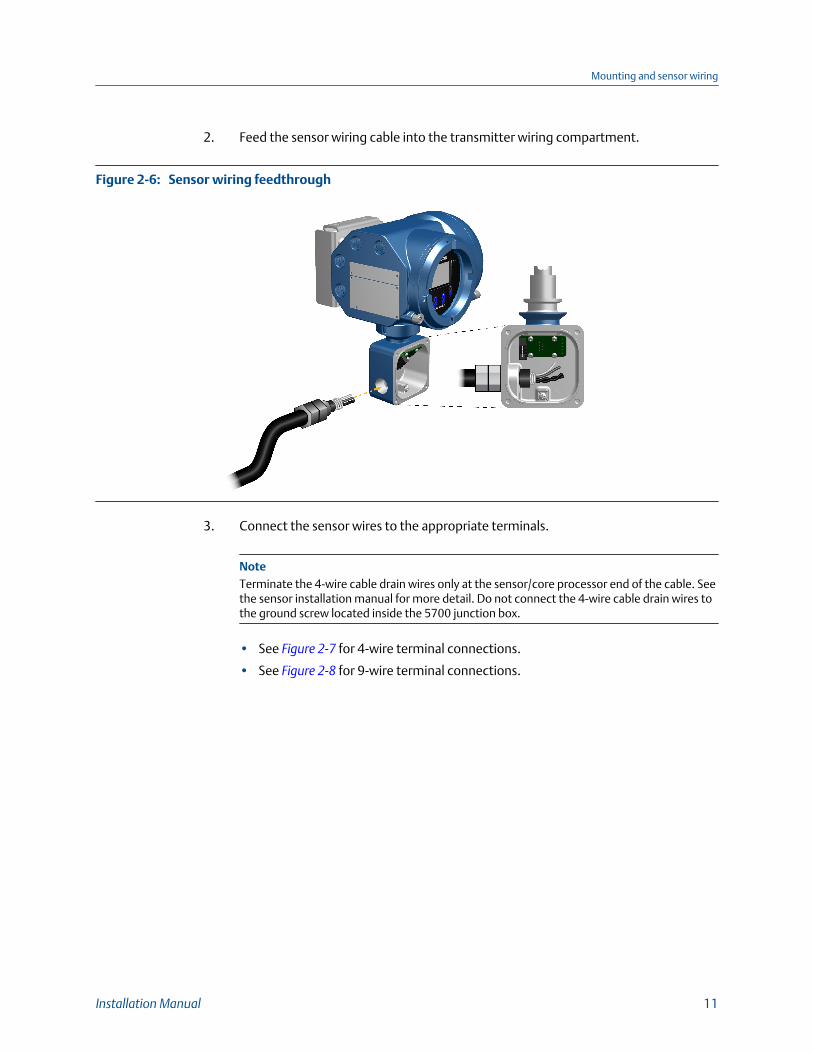
2. Feed the sensor wiring cable into the transmitter wiring compartment.
Sensor wiring feedthroughFigure 2-6:
3. Connect the sensor wires to the appropriate terminals.
NoteTerminate the 4-wire cable drain wires only at the sensor/core processor end of the cable. Seethe sensor installation manual for more detail. Do not connect the 4-wire cable drain wires tothe ground screw located inside the 5700 junction box.
• See Figure 2-7 for 4-wire terminal connections.
• See Figure 2-8 for 9-wire terminal connections.
Mounting and sensor wiring
Installation Manual 11
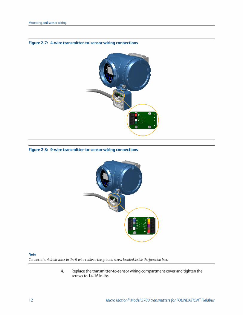
4-wire transmitter-to-sensor wiring connectionsFigure 2-7:
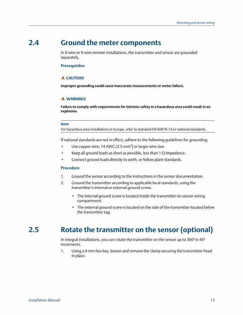
9-wire transmitter-to-sensor wiring connectionsFigure 2-8:
NoteConnect the 4 drain wires in the 9-wire cable to the ground screw located inside the junction box.
4. Replace the transmitter-to-sensor wiring compartment cover and tighten thescrews to 14-16 in-lbs.
Mounting and sensor wiring
12 Micro Motion® Model 5700 transmitters for FOUNDATION™ Fieldbus
2.4 Ground the meter componentsIn 4-wire or 9-wire remote installations, the transmitter and sensor are groundedseparately.
Prerequisites
CAUTION!
Improper grounding could cause inaccurate measurements or meter failure.
WARNING!
Failure to comply with requirements for intrinsic safety in a hazardous area could result in anexplosion.
NoteFor hazardous area installations in Europe, refer to standard EN 60079-14 or national standards.
If national standards are not in effect, adhere to the following guidelines for grounding:
• Use copper wire, 14 AWG (2.5 mm2) or larger wire size.
• Keep all ground leads as short as possible, less than 1 Ω impedance.
• Connect ground leads directly to earth, or follow plant standards.
Procedure
1. Ground the sensor according to the instructions in the sensor documentation.
2. Ground the transmitter according to applicable local standards, using thetransmitter’s internal or external ground screw.
• The internal ground screw is located inside the transmitter-to-sensor wiringcompartment.
• The external ground screw is located on the side of the transmitter located belowthe transmitter tag.
2.5 Rotate the transmitter on the sensor (optional)In integral installations, you can rotate the transmitter on the sensor up to 360º in 45ºincrements.
1. Using a 4 mm hex key, loosen and remove the clamp securing the transmitter headin place.
Mounting and sensor wiring
Installation Manual 13

Removal of the sensor clampFigure 2-9:
2. Gently lift the transmitter straight up, and rotate the transmitter to the desiredposition.
You can rotate the transmitter to any of the eight positions, but a stop exists thatwill not allow a full 360° rotation.
Rotation of the transmitter headFigure 2-10:
Mounting and sensor wiring
14 Micro Motion® Model 5700 transmitters for FOUNDATION™ Fieldbus
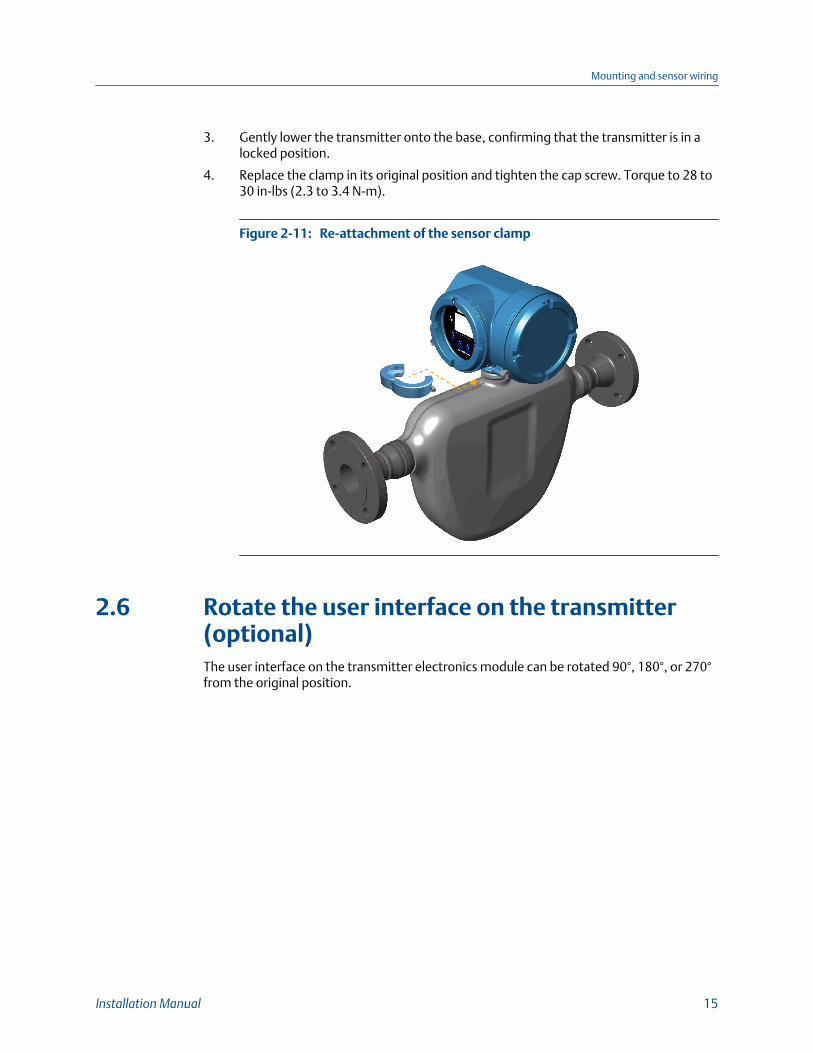
3. Gently lower the transmitter onto the base, confirming that the transmitter is in alocked position.
4. Replace the clamp in its original position and tighten the cap screw. Torque to 28 to30 in-lbs (2.3 to 3.4 N-m).
Re-attachment of the sensor clampFigure 2-11:
2.6 Rotate the user interface on the transmitter(optional)The user interface on the transmitter electronics module can be rotated 90°, 180°, or 270°from the original position.
Mounting and sensor wiring
Installation Manual 15

Display componentsFigure 2-12:
A. Transmitter housingB. Sub-bezelC. Display moduleD. Display screwsE. End-cap clampF. Cap screwG. Display cover
Procedure
1. Shut off power to the unit.
WARNING!
If the transmitter is in a hazardous area, wait five minutes after disconnecting the powerbefore opening the enclosure.
2. Loosen and rotate the end cap clamp so that it does not interfere with the cover.
Mounting and sensor wiring
16 Micro Motion® Model 5700 transmitters for FOUNDATION™ Fieldbus
3. Turn the display cover counterclockwise to remove it from the main enclosure.
4. Carefully loosen the captive display screws while holding the display module inplace.
5. Carefully pull the display module out of the main enclosure.
6. Rotate the display module to the desired position.
7. Gently press the display module back onto the connector.
8. Tighten display screws.
9. Place the display cover onto the main enclosure.
10. Turn the display cover clockwise until it is fully seated.
11. Replace the end-cap clamp by tightening the cap screw.
12. Restore power to the transmitter.
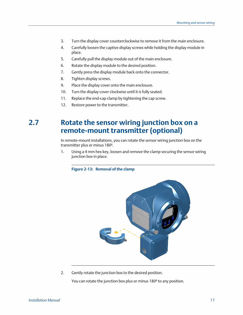
2.7 Rotate the sensor wiring junction box on aremote-mount transmitter (optional)In remote-mount installations, you can rotate the sensor wiring junction box on thetransmitter plus or minus 180º.
1. Using a 4 mm hex key, loosen and remove the clamp securing the sensor wiringjunction box in place.
Removal of the clampFigure 2-13:
2. Gently rotate the junction box to the desired position.
You can rotate the junction box plus or minus 180º to any position.
Mounting and sensor wiring
Installation Manual 17

Rotation of the sensor wiring junction boxFigure 2-14:
3. Gently set the junction box into its new position, confirming that the position islocked.
4. Replace the clamp in its original position and tighten the cap screw. Torque to 28 to30 in-lbs (2.3 to 3.4 N-m).
Re-attachment of the clampFigure 2-15:
Mounting and sensor wiring
18 Micro Motion® Model 5700 transmitters for FOUNDATION™ Fieldbus
3 Wiring the channelsTopics covered in this chapter:
• Access the wiring channels
• I/O wiring
• FISCO-input entity parameters
• Wiring for nonhazardous installations
• Wiring for hazardous installations
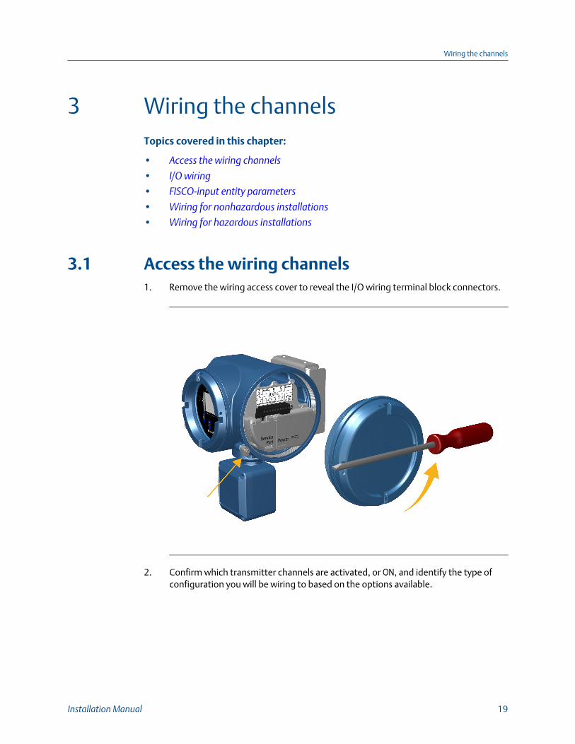
3.1 Access the wiring channels1. Remove the wiring access cover to reveal the I/O wiring terminal block connectors.
2. Confirm which transmitter channels are activated, or ON, and identify the type ofconfiguration you will be wiring to based on the options available.
Wiring the channels
Installation Manual 19

Activated channel identificationFigure 3-1:
Available channel configurationsTable 3-1:
Output Channel A B C
Wiring terminals 1 2 5 6 7 8
Outputs options FOUNDATION™ field-bus
mA Fixed Frequency
Discrete Output
3. (Recommended) Record the channel and wiring configuration on the label providedinside the transmitter housing cover.
Channel and wiring configurations labelFigure 3-2:
Wiring the channels
20 Micro Motion® Model 5700 transmitters for FOUNDATION™ Fieldbus
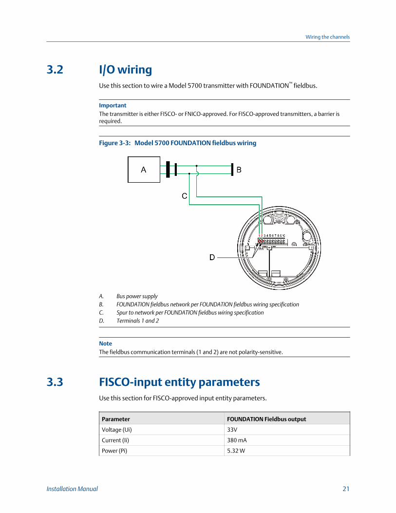
3.2 I/O wiringUse this section to wire a Model 5700 transmitter with FOUNDATION™ fieldbus.
ImportantThe transmitter is either FISCO- or FNICO-approved. For FISCO-approved transmitters, a barrier isrequired.
Model 5700 FOUNDATION fieldbus wiringFigure 3-3:
A. Bus power supplyB. FOUNDATION fieldbus network per FOUNDATION fieldbus wiring specificationC. Spur to network per FOUNDATION fieldbus wiring specificationD. Terminals 1 and 2
NoteThe fieldbus communication terminals (1 and 2) are not polarity-sensitive.
3.3 FISCO-input entity parametersUse this section for FISCO-approved input entity parameters.
Parameter FOUNDATION Fieldbus output
Voltage (Ui) 33V
Current (Ii) 380 mA
Power (Pi) 5.32 W
Wiring the channels
Installation Manual 21

Parameter FOUNDATION Fieldbus output
Internal capacitance (Ci) 0.27 nF
Internal inductance (Li) 5 μH
3.4 Wiring for nonhazardous installationsFollow these procedures for explosion-proof, nonincendive, or nonhazardous installations.
3.4.1 Wire the mA output for nonhazardous installationsPrerequisites
ImportantMeter installation and wiring should be performed only by suitably-trained personnel using theappropriate government and corporate safety standards.
Procedure
Wire to the appropriate output terminal and pins.
mA output wiringFigure 3-4:
A ED
CB
A. mA outputB. Channel BC. 10–30 VDC (maximum)D. Loop resistorE. Measurement device
Related information
mA Output loop resistance
Wiring the channels
22 Micro Motion® Model 5700 transmitters for FOUNDATION™ Fieldbus
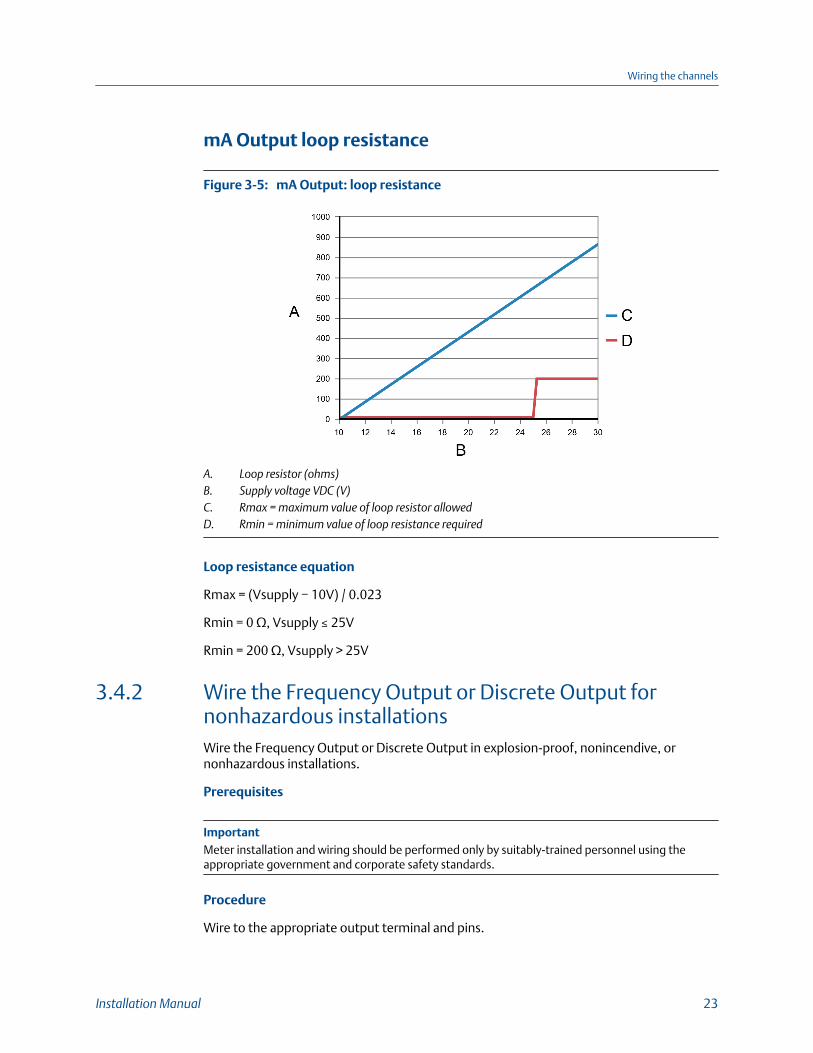
mA Output loop resistance
mA Output: loop resistanceFigure 3-5:
A. Loop resistor (ohms)B. Supply voltage VDC (V)C. Rmax = maximum value of loop resistor allowedD. Rmin = minimum value of loop resistance required
Loop resistance equation
Rmax = (Vsupply − 10V) / 0.023
Rmin = 0 Ω, Vsupply ≤ 25V
Rmin = 200 Ω, Vsupply > 25V
3.4.2 Wire the Frequency Output or Discrete Output fornonhazardous installationsWire the Frequency Output or Discrete Output in explosion-proof, nonincendive, ornonhazardous installations.
Prerequisites
ImportantMeter installation and wiring should be performed only by suitably-trained personnel using theappropriate government and corporate safety standards.
Procedure
Wire to the appropriate output terminal and pins.
Wiring the channels
Installation Manual 23
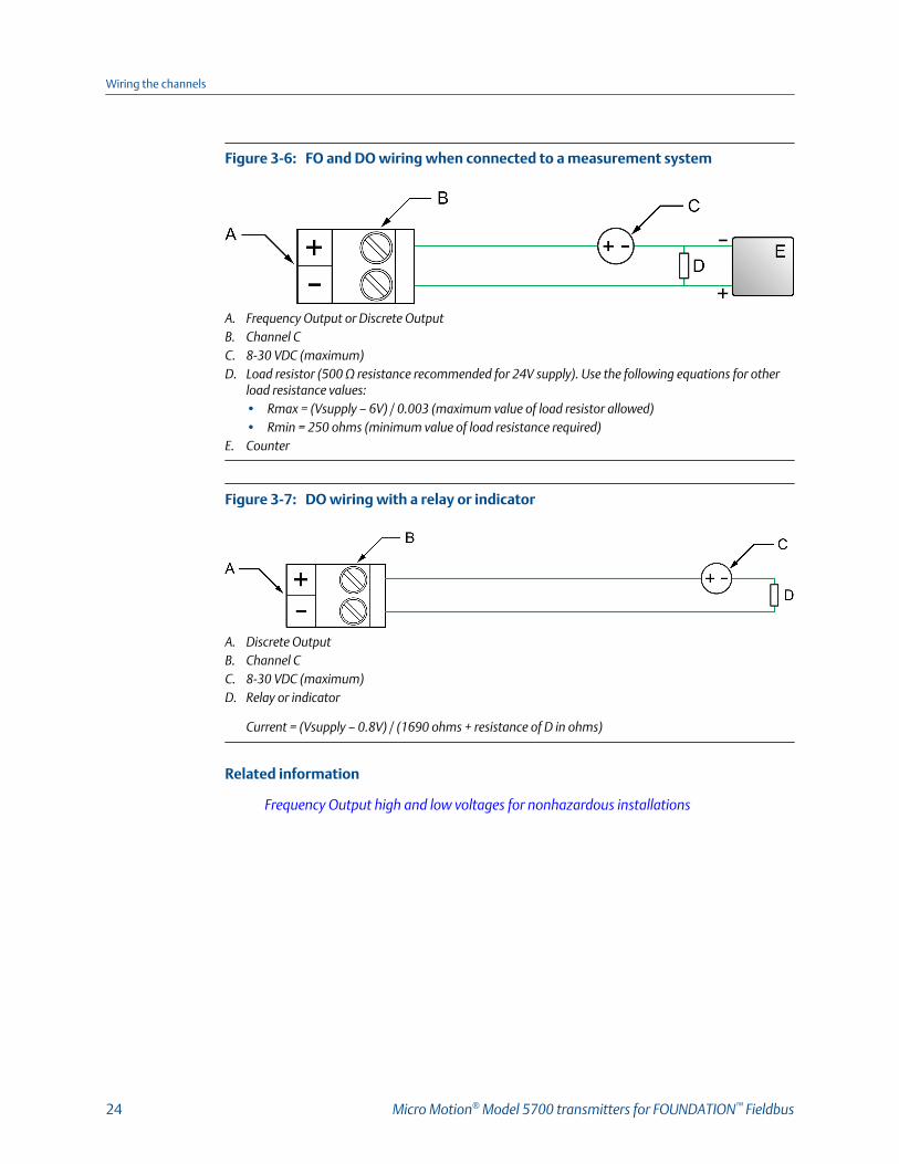
FO and DO wiring when connected to a measurement systemFigure 3-6:
A. Frequency Output or Discrete OutputB. Channel CC. 8-30 VDC (maximum)D. Load resistor (500 Ω resistance recommended for 24V supply). Use the following equations for other
load resistance values:• Rmax = (Vsupply – 6V) / 0.003 (maximum value of load resistor allowed)• Rmin = 250 ohms (minimum value of load resistance required)
E. Counter
DO wiring with a relay or indicatorFigure 3-7:
A. Discrete OutputB. Channel CC. 8-30 VDC (maximum)D. Relay or indicator
Current = (Vsupply – 0.8V) / (1690 ohms + resistance of D in ohms)
Related information
Frequency Output high and low voltages for nonhazardous installations
Wiring the channels
24 Micro Motion® Model 5700 transmitters for FOUNDATION™ Fieldbus

Frequency Output high and low voltages for nonhazardousinstallations
24VDC supplyFigure 3-8:
A. Output voltage (V)B. Load resistance RL (Ω)C. Low voltageD. High voltageE. Voltage (volts)F. Time
High and low voltage equations
High voltage ≈ (Vsupply – 0.8) * RL / (1706 + RL)
Low voltage ≈ 0.0007 * RL
3.5 Wiring for hazardous installationsFollow these instructions for hazardous installations.
DANGER!
Improper wiring in a hazardous environment can cause an explosion. Install the transmitteronly in an area that complies with the hazardous classification tag on the transmitter.
Wiring the channels
Installation Manual 25
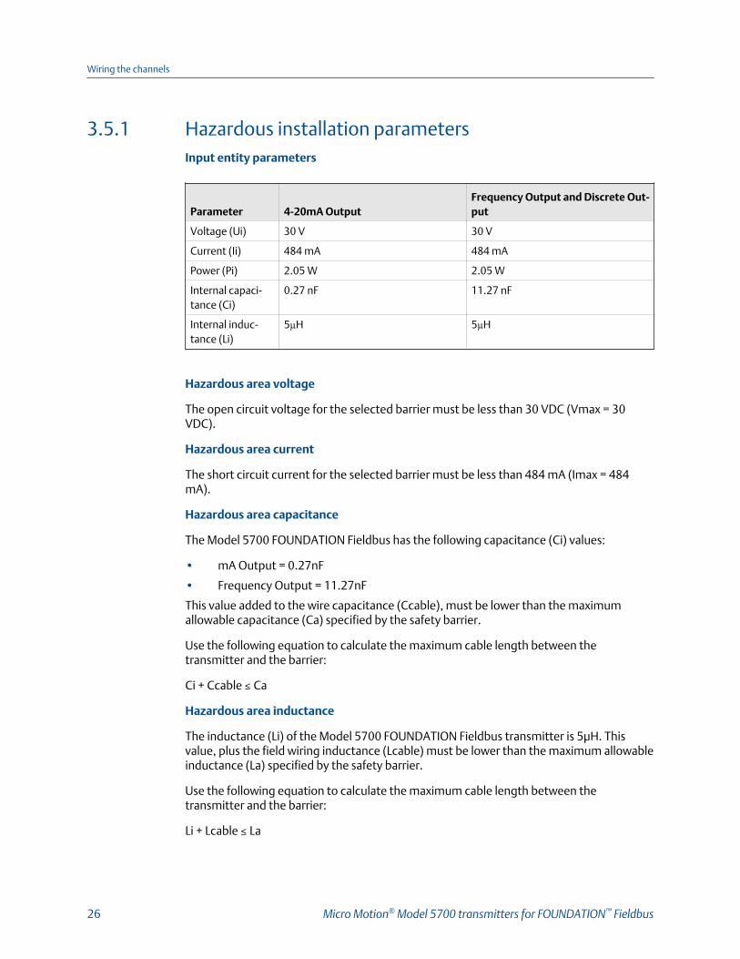
3.5.1 Hazardous installation parametersInput entity parameters
Parameter 4-20mA OutputFrequency Output and Discrete Out-put
Voltage (Ui) 30 V 30 V
Current (Ii) 484 mA 484 mA
Power (Pi) 2.05 W 2.05 W
Internal capaci-tance (Ci)
0.27 nF 11.27 nF
Internal induc-tance (Li)
5µH 5µH
Hazardous area voltage
The open circuit voltage for the selected barrier must be less than 30 VDC (Vmax = 30VDC).
Hazardous area current
The short circuit current for the selected barrier must be less than 484 mA (Imax = 484mA).
Hazardous area capacitance
The Model 5700 FOUNDATION Fieldbus has the following capacitance (Ci) values:
• mA Output = 0.27nF
• Frequency Output = 11.27nF
This value added to the wire capacitance (Ccable), must be lower than the maximumallowable capacitance (Ca) specified by the safety barrier.
Use the following equation to calculate the maximum cable length between thetransmitter and the barrier:
Ci + Ccable ≤ Ca
Hazardous area inductance
The inductance (Li) of the Model 5700 FOUNDATION Fieldbus transmitter is 5μH. Thisvalue, plus the field wiring inductance (Lcable) must be lower than the maximum allowableinductance (La) specified by the safety barrier.
Use the following equation to calculate the maximum cable length between thetransmitter and the barrier:
Li + Lcable ≤ La
Wiring the channels
26 Micro Motion® Model 5700 transmitters for FOUNDATION™ Fieldbus

3.5.2 Wire the mA Output for hazardous installationsPrerequisites
ImportantMeter installation and wiring should be performed only by suitably-trained personnel using theappropriate government and corporate safety standards.
Procedure
Wire to the appropriate output terminal and pins.
mA Output wiring in a hazardous areaFigure 3-9:
A. mA OutputB. Channel BC. 10–30 VDC (maximum)D. Loop resistorE. Measurement deviceF. Safety barrierG. Rbarrier
Add the Rbarrier and loop resistor D together to determine the proper Supply Voltage VDC(Volts). See mA Output loop resistance.
Wiring the channels
Installation Manual 27
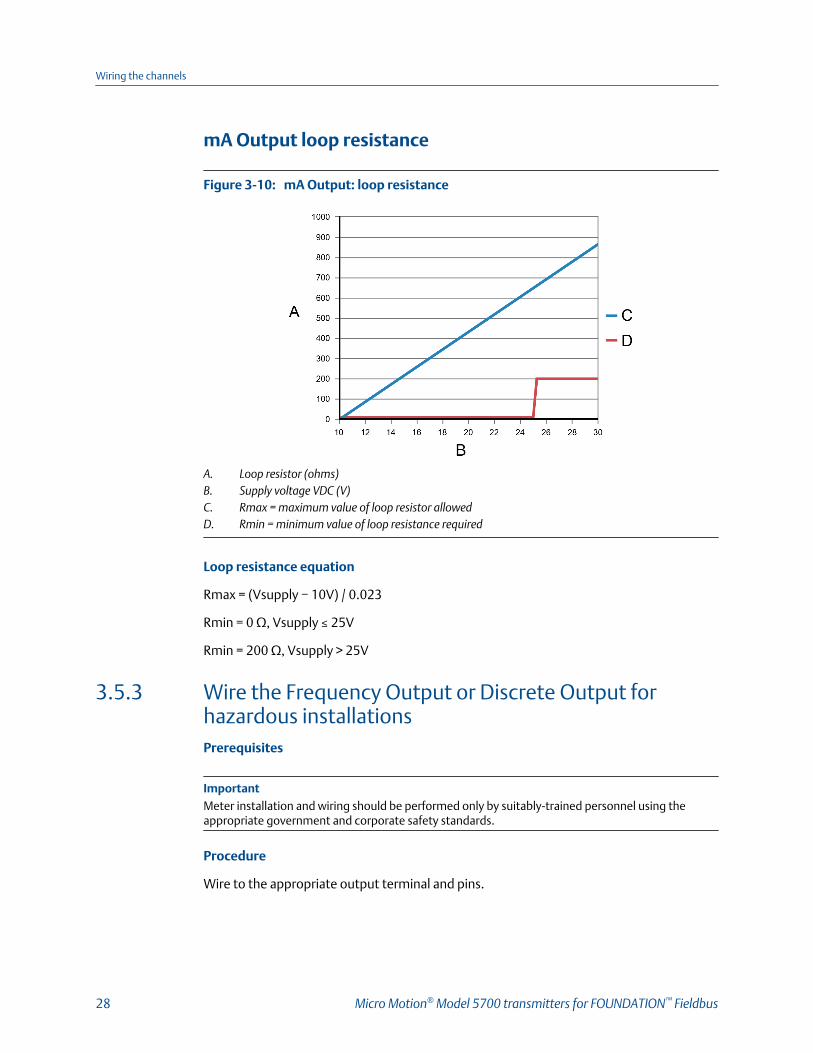
mA Output loop resistance
mA Output: loop resistanceFigure 3-10:
A. Loop resistor (ohms)B. Supply voltage VDC (V)C. Rmax = maximum value of loop resistor allowedD. Rmin = minimum value of loop resistance required
Loop resistance equation
Rmax = (Vsupply − 10V) / 0.023
Rmin = 0 Ω, Vsupply ≤ 25V
Rmin = 200 Ω, Vsupply > 25V
3.5.3 Wire the Frequency Output or Discrete Output forhazardous installationsPrerequisites
ImportantMeter installation and wiring should be performed only by suitably-trained personnel using theappropriate government and corporate safety standards.
Procedure
Wire to the appropriate output terminal and pins.
Wiring the channels
28 Micro Motion® Model 5700 transmitters for FOUNDATION™ Fieldbus
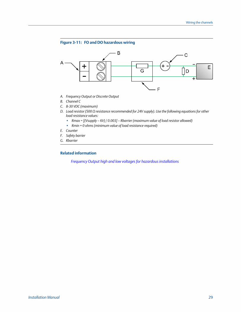
FO and DO hazardous wiringFigure 3-11:
A. Frequency Output or Discrete OutputB. Channel CC. 8-30 VDC (maximum)D. Load resistor (500 Ω resistance recommended for 24V supply). Use the following equations for other
load resistance values:• Rmax = [(Vsupply – 6V) / 0.003] – Rbarrier (maximum value of load resistor allowed)• Rmin = 0 ohms (minimum value of load resistance required)
E. CounterF. Safety barrierG. Rbarrier
Related information
Frequency Output high and low voltages for hazardous installations
Wiring the channels
Installation Manual 29
Frequency Output high and low voltages for hazardousinstallations
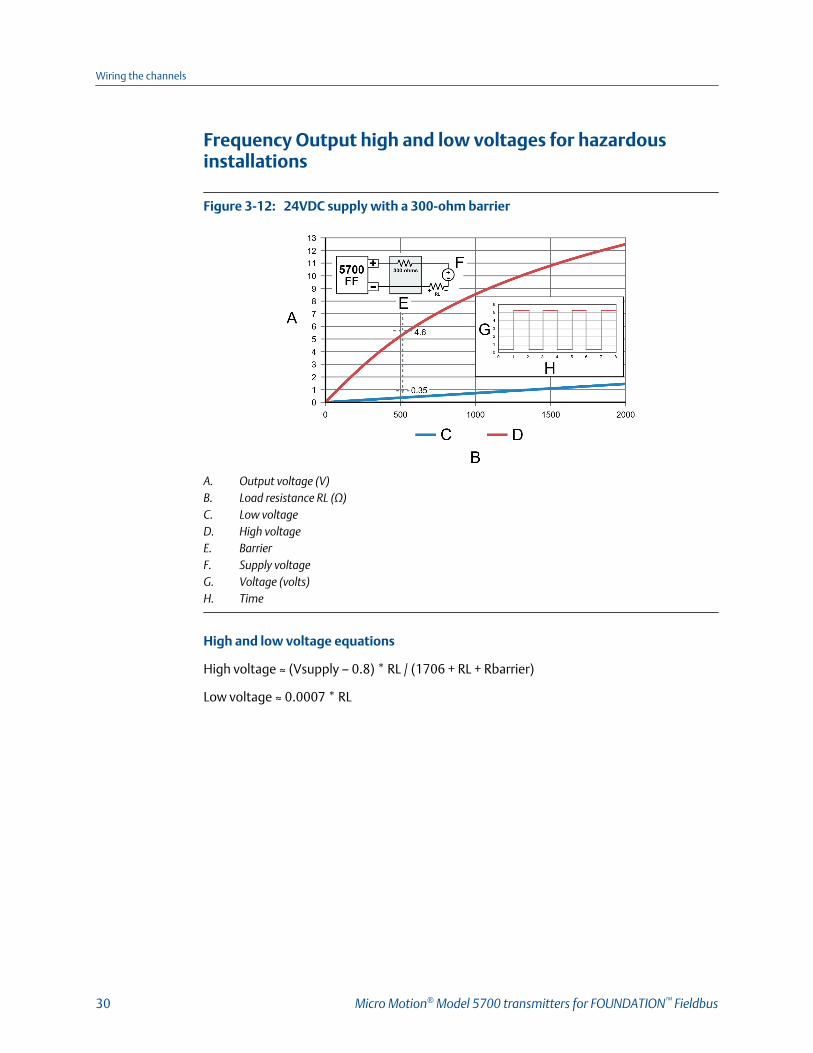
24VDC supply with a 300-ohm barrierFigure 3-12:
A. Output voltage (V)B. Load resistance RL (Ω)C. Low voltageD. High voltageE. BarrierF. Supply voltageG. Voltage (volts)H. Time
High and low voltage equations
High voltage ≈ (Vsupply – 0.8) * RL / (1706 + RL + Rbarrier)
Low voltage ≈ 0.0007 * RL
Wiring the channels
30 Micro Motion® Model 5700 transmitters for FOUNDATION™ Fieldbus
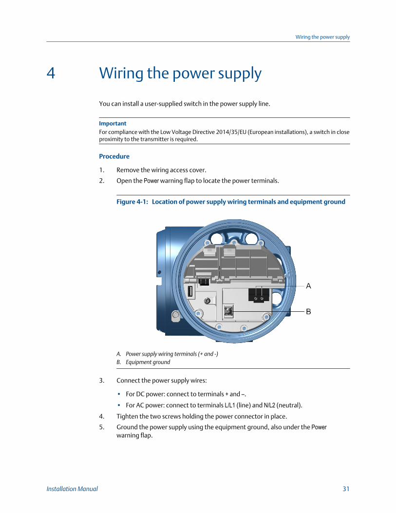
4 Wiring the power supply
You can install a user-supplied switch in the power supply line.
ImportantFor compliance with the Low Voltage Directive 2014/35/EU (European installations), a switch in closeproximity to the transmitter is required.
Procedure
1. Remove the wiring access cover.
2. Open the Power warning flap to locate the power terminals.
Location of power supply wiring terminals and equipment groundFigure 4-1:
A. Power supply wiring terminals (+ and -)B. Equipment ground
3. Connect the power supply wires:
• For DC power: connect to terminals + and –.
• For AC power: connect to terminals L/L1 (line) and N/L2 (neutral).
4. Tighten the two screws holding the power connector in place.
5. Ground the power supply using the equipment ground, also under the Powerwarning flap.
Wiring the power supply
Installation Manual 31

5 Power up the transmitter
The transmitter must be powered up for all configuration and commissioning tasks, or forprocess measurement.
1. Ensure that all transmitter and sensor covers and seals are closed.
WARNING!
To prevent ignition of flammable or combustible atmospheres, ensure that all coversand seals are tightly closed. For hazardous area installations, applying power whilehousing covers are removed or loose can cause an explosion.
2. Turn on the electrical power at the power supply.
Postrequisites
Although the sensor is ready to receive process fluid shortly after power-up, the electronicscan take up to 10 minutes to reach thermal equilibrium. Therefore, if this is the initialstartup, or if power has been off long enough to allow components to reach ambienttemperature, allow the electronics to warm up for approximately 10 minutes beforerelying on process measurements. During this warm-up period, you may observe minormeasurement instability or inaccuracy.
Power up the transmitter
32 Micro Motion® Model 5700 transmitters for FOUNDATION™ Fieldbus

6 Guided Setup
At initial startup of the transmitter, the guided configuration screen appears on thetransmitter display. This tool guides you through basic configuration of the transmitter.The guided setup allows you to upload configuration files, set the transmitter displayoptions, configure channels, and review sensor calibration data.
Guided Setup
Installation Manual 33
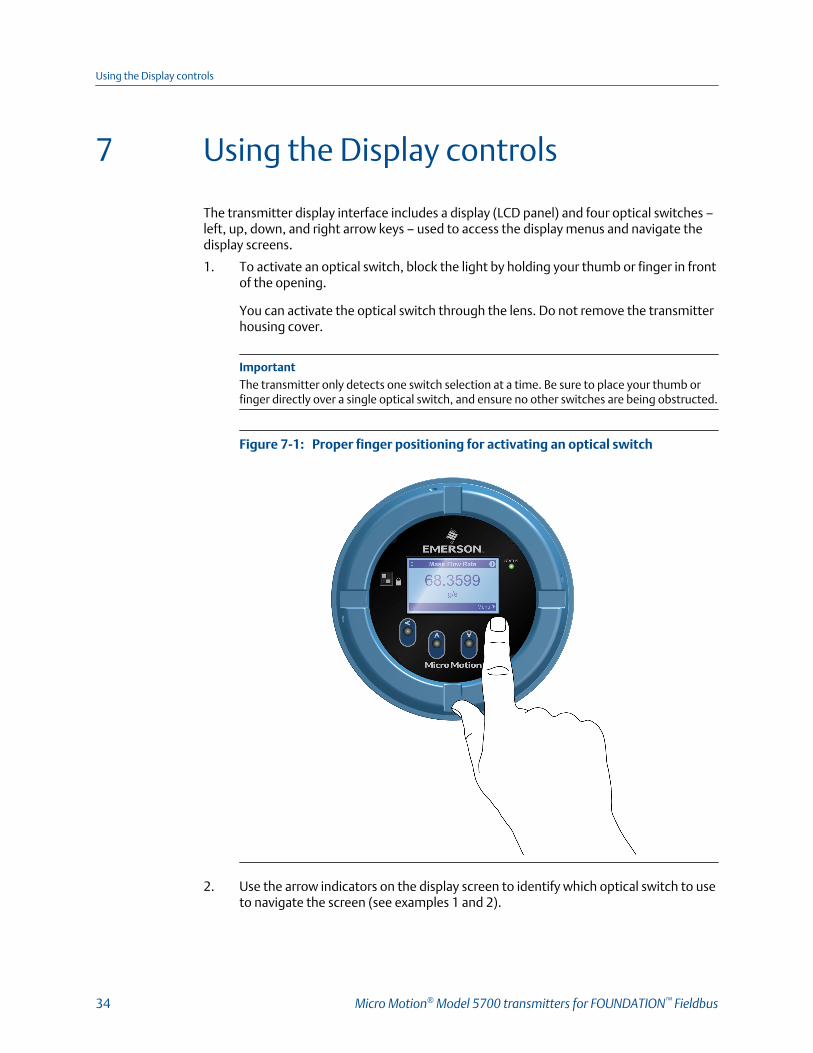
7 Using the Display controls
The transmitter display interface includes a display (LCD panel) and four optical switches –left, up, down, and right arrow keys – used to access the display menus and navigate thedisplay screens.
1. To activate an optical switch, block the light by holding your thumb or finger in frontof the opening.
You can activate the optical switch through the lens. Do not remove the transmitterhousing cover.
ImportantThe transmitter only detects one switch selection at a time. Be sure to place your thumb orfinger directly over a single optical switch, and ensure no other switches are being obstructed.
Proper finger positioning for activating an optical switchFigure 7-1:
2. Use the arrow indicators on the display screen to identify which optical switch to useto navigate the screen (see examples 1 and 2).
Using the Display controls
34 Micro Motion® Model 5700 transmitters for FOUNDATION™ Fieldbus

ImportantWhen using the arrow keys, you must first activate the optical switch then release the sameswitch by removing your finger from the glass to move up, down, right, left or to make aselection. To enable auto-scroll when navigating up or down, activate the appropriate switchand continue to hold for one second. Release the switch when the desired selection ishighlighted.
Example 1: Active arrow indicators on the transmitter displayFigure 7-2:
Example 2: Active arrow indicators on the transmitter displayFigure 7-3:
Using the Display controls
Installation Manual 35

8 Available Service Port connection
Use the service port connection to download or upload data from/to the transmitter.
To interface with the service port, use:
• Any commonly-available USB drive
NoteThe USB drive must be in FAT format. The transmitter does not recognize NTFS format.
• The standard USB cable provided by Micro Motion to connect the Model 5700transmitter to the PC
WARNING!
If the transmitter is in a hazardous area, do not remove the housing cover while power is beingsupplied to the unit. Removing the housing cover while power is supplied to the unit couldcause an explosion. To access the service port in a hazardous environment, be sure to removepower from the transmitter and wait 5 minutes before removing the housing cover.
The service port connection is located under the Service Port warning flap at the wiring access points.
Available Service Port connection
36 Micro Motion® Model 5700 transmitters for FOUNDATION™ Fieldbus

Available Service Port connection
Installation Manual 37

*MMI-20029969*MMI-20029969
Rev AA
2016
Micro Motion Inc. USAWorldwide Headquarters7070 Winchester CircleBoulder, Colorado 80301T +1 303-527-5200T +1 800-522-6277F +1 303-530-8459www.micromotion.com
Micro Motion EuropeEmerson Process ManagementNeonstraat 16718 WX EdeThe NetherlandsT +31 (0) 70 413 6666F +31 (0) 318 495 556www.micromotion.nl
Micro Motion AsiaEmerson Process Management1 Pandan CrescentSingapore 128461Republic of SingaporeT +65 6777-8211F +65 6770-8003
Micro Motion United KingdomEmerson Process Management LimitedHorsfield WayBredbury Industrial EstateStockport SK6 2SU U.K.T +44 0870 240 1978F +44 0800 966 181
Micro Motion JapanEmerson Process Management1-2-5, Higashi ShinagawaShinagawa-kuTokyo 140-0002 JapanT +81 3 5769-6803F +81 3 5769-6844
©2016 Micro Motion, Inc. All rights reserved.
The Emerson logo is a trademark and service mark of EmersonElectric Co. Micro Motion, ELITE, ProLink, MVD and MVD DirectConnect marks are marks of one of the Emerson ProcessManagement family of companies. All other marks are property oftheir respective owners.