Micro Motion D and DL Sensors - Emerson D and DL Sensors ATEX Installation Instructions • For...
24
Installation Instructions P/N MMI-20010137, Rev. A June 2007 ATEX Installation Instructions for Micro Motion ® D and DL Sensors For ATEX-approved sensor installations
Transcript of Micro Motion D and DL Sensors - Emerson D and DL Sensors ATEX Installation Instructions • For...

Installation InstructionsP/N MMI-20010137, Rev. AJune 2007
ATEX Installation Instructions for Micro Motion® D and DL Sensors
For ATEX-approved sensor installations

Information affixed to equipment that complies with the Pressure Equipment Directive can be found on the internet at www.micromotion.com/library.
©2007, Micro Motion, Inc. All rights reserved. ELITE and ProLink are registered trademarks, and MVD and MVD Direct Connect are trademarks of Micro Motion, Inc., Boulder, Colorado. Micro Motion is a registered trade name of Micro Motion, Inc., Boulder, Colorado. The Micro Motion and Emerson logos are trademarks and service marks of Emerson Electric Co. All other trademarks are property of their respective owners.
Note: For hazardous installations in Europe, refer to standard EN 60079-14 if national standards do not apply.
1
D and DL SensorsATEX Installation Instructions
• For installing the following Micro Motion sensors:
- Models D150 and D300
- Models DH25, DH38, DH100, DH150, and DH300
- Models DT65, DT100, and DT150
- Models DL65, DL100, and DL200
Subject: Equipment type Sensor type D* *** * ****B
Manufactured and submitted for examination
Micro Motion, Inc.
Address Boulder, Co. 80301, USA
Basis for examination: Annex II of Directive 94/9/EC
Standard basis EN 50014:1997 +A1-A2 General requirements
EN 50020:1994 Intrinsic safety ´i´
EN 50281-1-1:1998 Dust Evaluation ´D´
Code for type of protection EEx ib IIB/IIC T1–T6
ATEX Installation Instructions

D and DL Sensors
2 ATEX Installation Instructions
1) Subject and type
Sensor type D* *** * ****B
Instead of the *** letters and numerals will be inserted which characterize the following modifications:
2) Description
The flow sensor in combination with a transmitter is used for flow measurement. The flow sensor consists of magnetically excited oscillating tubes. The sensor electrical components are coils, resistors, temperature sensors, terminals and connectors.
The sensor may also be used for measurement of flammable substances, providing that the substances do not form an explosive atmosphere either permanently or frequently. If flammable substances are being measured, the sensor must be included in the recurrent pressure test.
Amendment No. 1 to the ATEX certificate DMT 02 ATEX E 156 X reflects the revised Drive Coilparameters for D*100, DL100, and D*150 for compatibility with other certified ATEX transmitters.Sensors constructed using these revised coil parameters will be identified with a ConstructionIdentification Code (C.I.C.) of A1.
D * * * * * * * * B*
3 numerals for type of sensor
Construction Identification Code (CIC)(Shown approximately where stamped)

D and DL Sensors
ATEX Installation Instructions 3
3) Parameters
3.1) Type D* *** * ****B
3.1.1) Drive circuit
Parameters for terminals 1 and 2 (red and brown wires)
Remote Model 1700/2700 transmitter with core processor Model 700
Other Micro Motion certified transmitters
Voltage Up to 10,5 VDC Up to 11,4 VDC
Rated current of barrier fuse 160 mA 250 mA
Current Ii 2,45 A 1,14 A
Pi 2,54 W 1,2 W
Effective barrier capacitance Negligible Negligible
Effective barrier circuit resistance 4,32 ohms 10 ohms
Sensor type Inductivity [mH]Coil resistance @ –20 °C [Ohms]
Series resistance @ –20 °C [Ohms]
D*025 6,9 106,2 946,6
DH038 6,9 106,2 946,6
D*065 0,2 3,16 482,6
DL050X 0,2 3,16 189,3
DL065 0,2 3,16 482,6
D*100 32,8 108,7 59,3
DL100 32,8 108,7 59,3
D*150 32,8 108,7 59,3
DL200 3 35,8 9,5
D*300 3 35,8 9,5
Sensor type Inductivity [mH]Coil resistance @ +32 °C [Ohms]
Series resistance @ +32 °C [Ohms]
DT065 3 44 0
DT100 3 44 0
DT150 3 44 0

D and DL Sensors
4 ATEX Installation Instructions
3.1.2) Pick-off circuit (terminals 5,9 and 6,8; green/white and blue/grey wires)
3.1.3) Temperature circuit (terminals 3, 4 and 7; orange, yellow and violet wires)
Voltage Uo DC 17,3 V
Current Io 6,9 mA
Power Po 30 mW
Capacitance Co Negligible
Sensor type Inductivity [mH]Coil resistance @ –20 °C [Ohms]
D*025 6,9 106,2
DH038 6,9 106,2
D*065 0,2 3,16
DL050X 0,2 3,16
DL065 0,2 3,16
D*100 6,18 113,8
DL100 6,18 113,8
D*150 6,18 113,8
DL200 6,18 113,8
D*300 6,18 113,8
Sensor type Inductivity [mH]Coil resistance @ +32 °C [Ohms]
DT065 1,2 15,7
DT100 1,2 15,7
DT150 1,2 15,7
Voltage Uo DC 17,3 V
Current Io 26 mA
Power Po 112 mW
Capacitance Co Negligible
Inductance Lo Negligible
D and DL Sensors
ATEX Installation Instructions 5
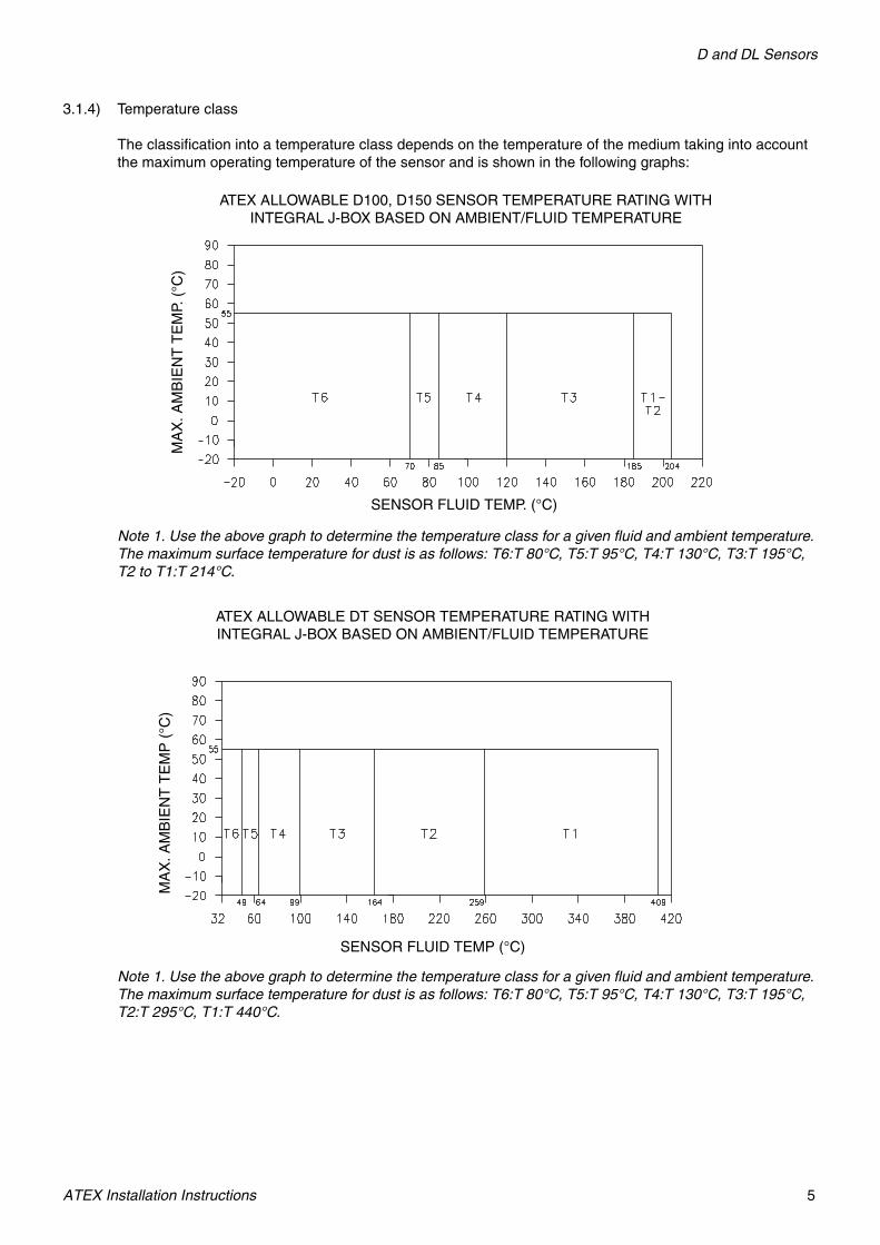
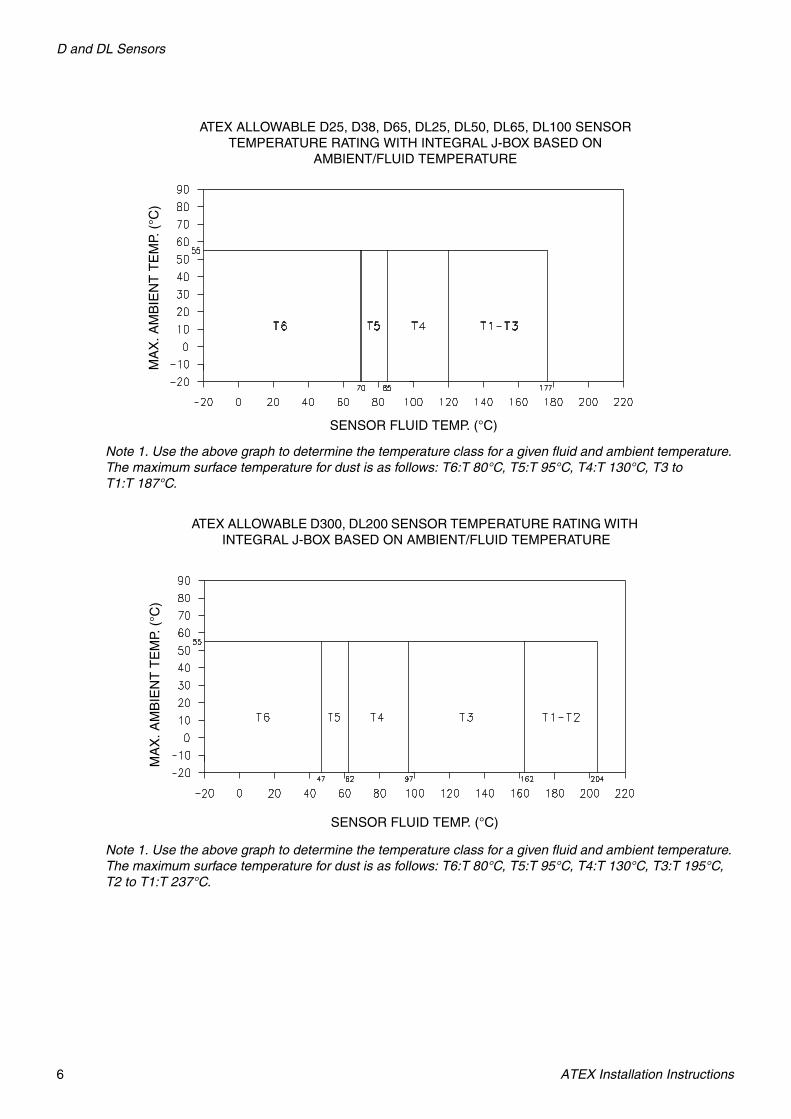
3.1.4) Temperature class
The classification into a temperature class depends on the temperature of the medium taking into account the maximum operating temperature of the sensor and is shown in the following graphs:
Note 1. Use the above graph to determine the temperature class for a given fluid and ambient temperature. The maximum surface temperature for dust is as follows: T6:T 80°C, T5:T 95°C, T4:T 130°C, T3:T 195°C, T2 to T1:T 214°C.
Note 1. Use the above graph to determine the temperature class for a given fluid and ambient temperature. The maximum surface temperature for dust is as follows: T6:T 80°C, T5:T 95°C, T4:T 130°C, T3:T 195°C, T2:T 295°C, T1:T 440°C.
ATEX ALLOWABLE D100, D150 SENSOR TEMPERATURE RATING WITH INTEGRAL J-BOX BASED ON AMBIENT/FLUID TEMPERATURE
MA
X. A
MB
IEN
T T
EM
P. (
°C)
SENSOR FLUID TEMP. (°C)
MA
X. A
MB
IEN
T T
EM
P (
°C)
SENSOR FLUID TEMP (°C)
ATEX ALLOWABLE DT SENSOR TEMPERATURE RATING WITH INTEGRAL J-BOX BASED ON AMBIENT/FLUID TEMPERATURE
D and DL Sensors
6 ATEX Installation Instructions
Note 1. Use the above graph to determine the temperature class for a given fluid and ambient temperature. The maximum surface temperature for dust is as follows: T6:T 80°C, T5:T 95°C, T4:T 130°C, T3 to T1:T 187°C.
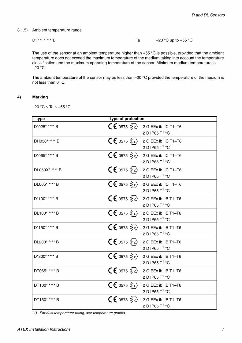
Note 1. Use the above graph to determine the temperature class for a given fluid and ambient temperature. The maximum surface temperature for dust is as follows: T6:T 80°C, T5:T 95°C, T4:T 130°C, T3:T 195°C, T2 to T1:T 237°C.
ATEX ALLOWABLE D25, D38, D65, DL25, DL50, DL65, DL100 SENSOR TEMPERATURE RATING WITH INTEGRAL J-BOX BASED ON
AMBIENT/FLUID TEMPERATUREM
AX
. AM
BIE
NT
TE
MP.
(°C
)
SENSOR FLUID TEMP. (°C)
ATEX ALLOWABLE D300, DL200 SENSOR TEMPERATURE RATING WITH INTEGRAL J-BOX BASED ON AMBIENT/FLUID TEMPERATURE
MA
X. A
MB
IEN
T T
EM
P. (
°C)
SENSOR FLUID TEMP. (°C)
D and DL Sensors
ATEX Installation Instructions 7
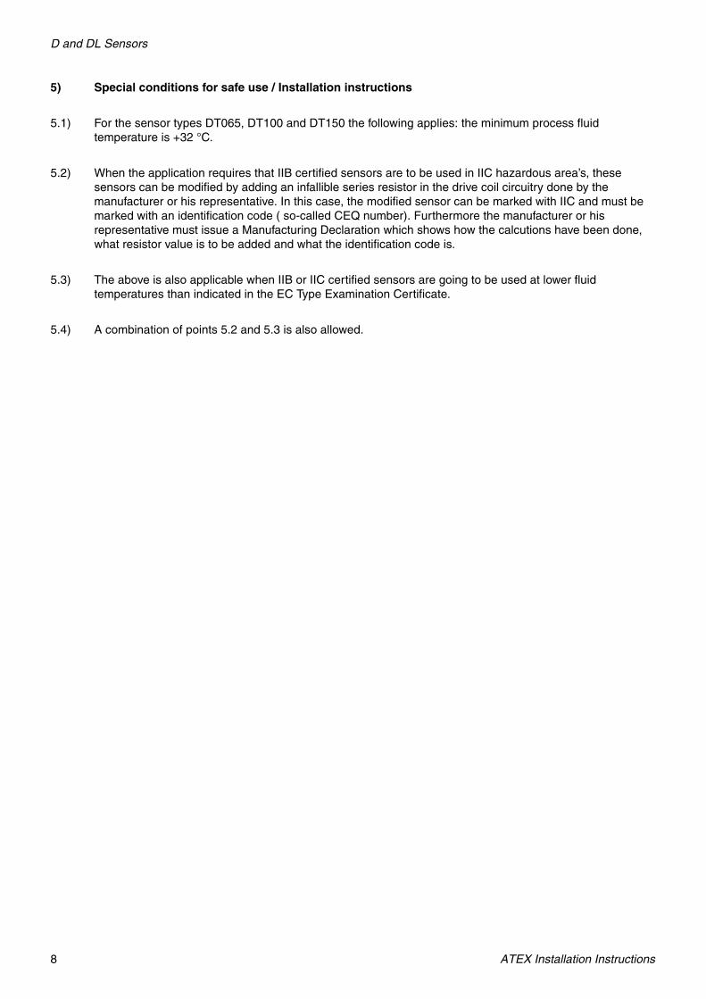
3.1.5) Ambient temperature range
The use of the sensor at an ambient temperature higher than +55 °C is possible, provided that the ambient temperature does not exceed the maximum temperature of the medium taking into account the temperature classification and the maximum operating temperature of the sensor. Minimum medium temperature is –20 °C.
The ambient temperature of the sensor may be less than –20 °C provided the temperature of the medium is not less than 0 °C.
4) Marking
–20 °C ≤ Ta ≤ +55 °C
D* *** * ****B Ta –20 °C up to +55 °C
- type - type of protection
D*025* **** B 0575 II 2 G EEx ib IIC T1–T6
II 2 D IP65 T1 °C
(1) For dust temperature rating, see temperature graphs.
DH038* **** B 0575 II 2 G EEx ib IIC T1–T6
II 2 D IP65 T1 °C
D*065* **** B 0575 II 2 G EEx ib IIC T1–T6
II 2 D IP65 T1 °C
DL050X* **** B 0575 II 2 G EEx ib IIC T1–T6
II 2 D IP65 T1 °C
DL065* **** B 0575 II 2 G EEx ib IIC T1–T6
II 2 D IP65 T1 °C
D*100* **** B 0575 II 2 G EEx ib IIB T1–T6
II 2 D IP65 T1 °C
DL100* **** B 0575 II 2 G EEx ib IIB T1–T6
II 2 D IP65 T1 °C
D*150* **** B 0575 II 2 G EEx ib IIB T1–T6
II 2 D IP65 T1 °C
DL200* **** B 0575 II 2 G EEx ib IIB T1–T6
II 2 D IP65 T1 °C
D*300* **** B 0575 II 2 G EEx ib IIB T1–T6
II 2 D IP65 T1 °C
DT065* **** B 0575 II 2 G EEx ib IIB T1–T6
II 2 D IP65 T1 °C
DT100* **** B 0575 II 2 G EEx ib IIB T1–T6
II 2 D IP65 T1 °C
DT150* **** B 0575 II 2 G EEx ib IIB T1–T6
II 2 D IP65 T1 °C
D and DL Sensors
8 ATEX Installation Instructions
5) Special conditions for safe use / Installation instructions
5.1) For the sensor types DT065, DT100 and DT150 the following applies: the minimum process fluid temperature is +32 °C.
5.2) When the application requires that IIB certified sensors are to be used in IIC hazardous area’s, these sensors can be modified by adding an infallible series resistor in the drive coil circuitry done by the manufacturer or his representative. In this case, the modified sensor can be marked with IIC and must be marked with an identification code ( so-called CEQ number). Furthermore the manufacturer or his representative must issue a Manufacturing Declaration which shows how the calcutions have been done, what resistor value is to be added and what the identification code is.
5.3) The above is also applicable when IIB or IIC certified sensors are going to be used at lower fluid temperatures than indicated in the EC Type Examination Certificate.
5.4) A combination of points 5.2 and 5.3 is also allowed.
9
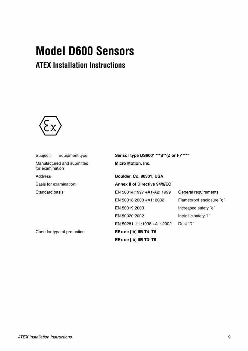
Model D600 SensorsATEX Installation Instructions
Subject: Equipment type Sensor type DS600* ***S**(Z or F)*****
Manufactured and submitted for examination
Micro Motion, Inc.
Address Boulder, Co. 80301, USA
Basis for examination: Annex II of Directive 94/9/EC
Standard basis EN 50014:1997 +A1-A2: 1999 General requirements
EN 50018:2000 +A1: 2002 Flameproof enclosure ´d´
EN 50019:2000 Increased safety ´e´
EN 50020:2002 Intrinsic safety ´i´
EN 50281-1-1:1998 +A1: 2002 Dust ´D´
Code for type of protection EEx de [ib] IIB T4–T6
EEx de [ib] IIB T3–T6
ATEX Installation Instructions

Model D600 Sensors
10 ATEX Installation Instructions
1) Subject and type
Sensor type DS600* ******(F or Z)*****
Instead of the *** letters and numerals will be inserted which characterize the following modifications:
Marking without influence to the type of protection
Letter for electronics interface
K = Integral booster amp with local core processorL = Integral booster amp with local core processor for
direct hostM = Integral booster amp with 9-wire junction boxN = Remote booster amp with local core processorO = Remote booster amp with local core processor for
direct hostP = Remote booster amp with 9-wire junction box
D S 6 0 0 * * * * * * Z * * * *
Marking without influence to the type of protection
Letter for conduit connections
Approval
F = Flameproof Terminal CompartmentZ = Increased Safety Terminal Compartment
S
Case option
S = Standard pressure containment
*

Model D600 Sensors
ATEX Installation Instructions 11
2) Description
The flow sensor DS600 in conjunction with a Micro Motion Transmitter is used for flow measurement. The flow sensor, which consists of magnetically exited oscillating tubes, contains as electrical components coils, temperature sensor, terminals, connectors and a Booster Amplifier.
The Booster Amplifier used with the Mass Flow Sensor Model D600 is certified as a component under KEMA 01 ATEX 2184 U. The Booster Amplifier may be used either integrally or remotely mounted in relation to the sensor body, depending upon the maximum fluid temperature. The Booster Amplifier is able to accept Micro Motion’s 9-Wire J-Box or Core Processor (Model 700) (certified as EEx ib IIB/IIC T5 under DMT 01 ATEX E 081 U) inputs.
The terminal compartment of the Booster Amplifier may be Certified as either a flame proof (EEx d) enclosure or an increased safety (EEx e) enclosure.
The Booster Amplifier additionally incorporates an intrinsically safe Junction Housing for termination and connection of the separately certified intrinsically safe transmitter and sensor wiring.
The drive coils are classified as EEx e. The pick-off coils and temperature sensor are standard designed and classified as EEx i.
By mounting the Core Processor (Model 700) directly to the Booster Amplifier the use of the unit will bemodified according to the following table:
3) Parameters
3.1) Electrical parameters: see Booster Amplifier Section.
3.2) Type DS600* ***S(K, L or M)*(F or Z)*****(Integral booster amplifier provided with 9-wire junction box or 4-wire core processor)
3.2.1) Ambient temperature range
Sensor DS600* ***S(N, O or P)*(F or Z)***** DS600* ***S(K, L or M)*(F or Z)*****
0575 II 2 G EEx de [ib] IIB T3–T6 0575 II 2 G EEx de [ib] IIB T4–T6
II 2 D IP65 T1 °C
(1) For dust temperature ratings, see temperature graphs.
II 2 D IP65 T1 °C
DS600* ***S(K, L or M)*(F or Z)***** Ta –20 °C up to +60 °C

Model D600 Sensors
12 ATEX Installation Instructions
3.2.2) Temperature class
The classification into a temperature class depends on the temperature of the medium taking into account the maximum operating temperature of the sensor and is shown in the following graph:
Note 1. Use the above graph to determine the temperature class for a given fluid and ambient temperature. The maximum surface temperature for dust is as follows: T6:T 80°C, T5:T 95°C, T4:T 128°C.
3.3) Type DS600* ***S(N, O or P)*(F or Z)*****(Remote booster amplifier provided with 9-wire junction box or 4-wire core processor)
ATEX ALLOWABLE D600 (EExe DRIVE COILS) SENSOR TEMPERATURE RATING WITH INTEGRAL BOOSTER WITH J-BOX OR CORE PROCESSOR
BASED ON AMBIENT/FLUID TEMPERATURE
MA
X. A
MB
IEN
T T
EM
P. (
°C)
SENSOR FLUID TEMP. (°C)
Model D600 Sensors
ATEX Installation Instructions 13
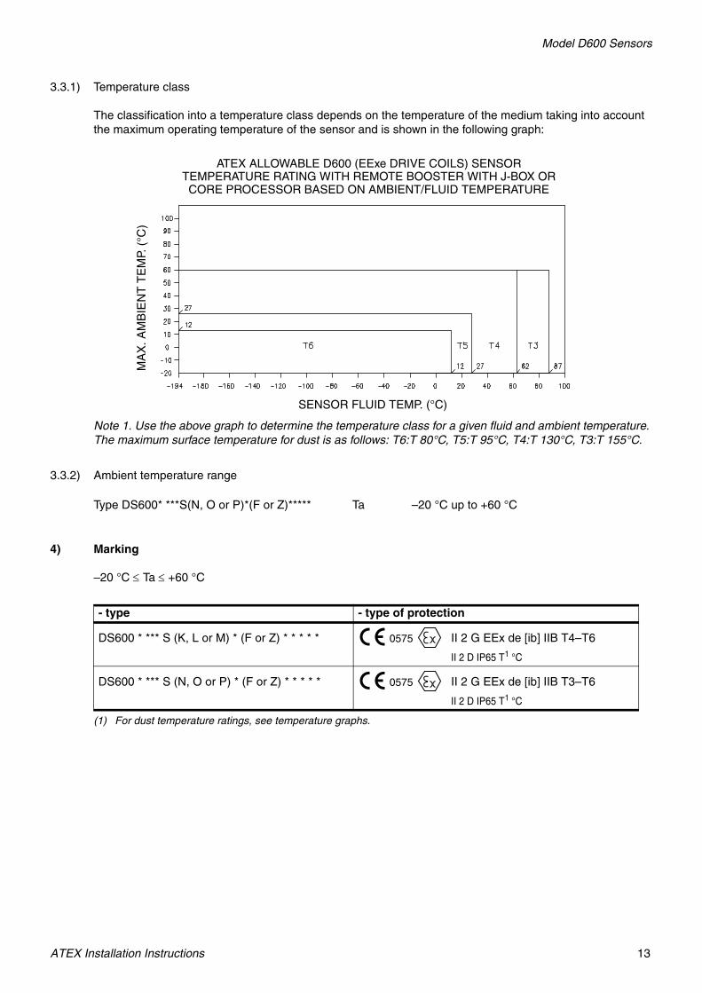
3.3.1) Temperature class
The classification into a temperature class depends on the temperature of the medium taking into account the maximum operating temperature of the sensor and is shown in the following graph:
Note 1. Use the above graph to determine the temperature class for a given fluid and ambient temperature. The maximum surface temperature for dust is as follows: T6:T 80°C, T5:T 95°C, T4:T 130°C, T3:T 155°C.
3.3.2) Ambient temperature range
4) Marking
–20 °C ≤ Ta ≤ +60 °C
Type DS600* ***S(N, O or P)*(F or Z)***** Ta –20 °C up to +60 °C
- type - type of protection
DS600 * *** S (K, L or M) * (F or Z) * * * * * 0575 II 2 G EEx de [ib] IIB T4–T6
II 2 D IP65 T1 °C
(1) For dust temperature ratings, see temperature graphs.
DS600 * *** S (N, O or P) * (F or Z) * * * * * 0575 II 2 G EEx de [ib] IIB T3–T6
II 2 D IP65 T1 °C
MA
X. A
MB
IEN
T T
EM
P. (
°C)
SENSOR FLUID TEMP. (°C)
ATEX ALLOWABLE D600 (EExe DRIVE COILS) SENSOR TEMPERATURE RATING WITH REMOTE BOOSTER WITH J-BOX OR CORE PROCESSOR BASED ON AMBIENT/FLUID TEMPERATURE

Model D600 Sensors
14 ATEX Installation Instructions
5) Special conditions for safe use / Installation instructions
5.1) For certified conduit installations a customer supplied Conduit Seal Fitting is required within 18″ of the enclosure.
5.2) Risk of Ignition of Hazardous Atmospheres — Disconnect equipment from supply circuit and wait 30 minutes before opening. Keep assembly tightly closed when in operation.
5.3) Explosion Hazard — Substitution of components may impair Intrinsic Safety.
5.4) For installation only with Micro Motion Booster Amplifier and Transmitters.

15
Booster AmplifierATEX Installation Drawings and Instructions
• For installing a booster amplifier to the following sensors:
- Booster amplifier with 4-wire core processor to D600 sensor
- Booster amplifier with 9-wire junction box to D600 sensor
Subject: Equipment type Booster amplifier
Manufactured and submitted for examination
Micro Motion, Inc.
Address Boulder, Co. 80301, USA
Basis for examination: Annex II of Directive 94/9/EC
Standard basis EN 50014:1997 General requirements
EN 50018:2000 Flameproof enclosure ´d´
EN 50019:2000 Increased safety ´e´
EN 50020:1994 Intrinsic safety ´i´
EN 50281-1-1:1998 Dust ´D´
Code for type of protection EEx d [ib] IIB T5orEEx de [ib] IIB T5
When Core Processor (Model 700) is Integrally Mounted to Booster Amplifier
EEx d [ib] IIB T6orEEx de [ib] IIB T6
When 9-Wire J-Box is Mounted on Booster Amp
ATEX Installation Instructions
Booster Amplifier
16 ATEX Installation Instructions
1) Subject and type
Booster amplifier
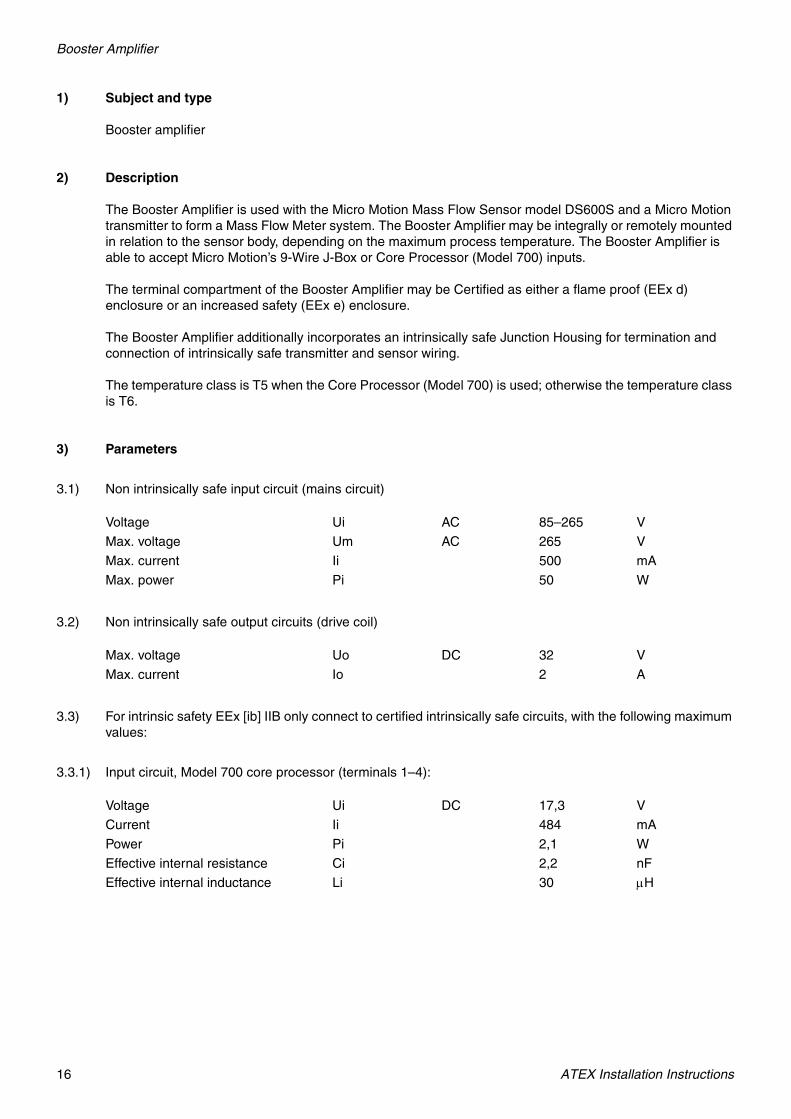
2) Description
The Booster Amplifier is used with the Micro Motion Mass Flow Sensor model DS600S and a Micro Motion transmitter to form a Mass Flow Meter system. The Booster Amplifier may be integrally or remotely mounted in relation to the sensor body, depending on the maximum process temperature. The Booster Amplifier is able to accept Micro Motion’s 9-Wire J-Box or Core Processor (Model 700) inputs.
The terminal compartment of the Booster Amplifier may be Certified as either a flame proof (EEx d) enclosure or an increased safety (EEx e) enclosure.
The Booster Amplifier additionally incorporates an intrinsically safe Junction Housing for termination and connection of intrinsically safe transmitter and sensor wiring.
The temperature class is T5 when the Core Processor (Model 700) is used; otherwise the temperature class is T6.
3) Parameters
3.1) Non intrinsically safe input circuit (mains circuit)
3.2) Non intrinsically safe output circuits (drive coil)
3.3) For intrinsic safety EEx [ib] IIB only connect to certified intrinsically safe circuits, with the following maximum values:
3.3.1) Input circuit, Model 700 core processor (terminals 1–4):
Voltage Ui AC 85–265 V
Max. voltage Um AC 265 V
Max. current Ii 500 mA
Max. power Pi 50 W
Max. voltage Uo DC 32 V
Max. current Io 2 A
Voltage Ui DC 17,3 V
Current Ii 484 mA
Power Pi 2,1 W
Effective internal resistance Ci 2,2 nF
Effective internal inductance Li 30 μH

Booster Amplifier
ATEX Installation Instructions 17
3.3.2) Input circuit, 9-wire junction box
3.3.2.1) Drive coil circuit (brown and red insulated wires)
3.3.2.2) Pick-off coils (green and white, blue and grey, insulated wires)
3.3.2.3) Temperature pass through wiring (violet, orange and yellow insulated wires)
3.4) Ambient temperature range
4) Marking
0575 II 2 G D
–40 °C ≤ Ta ≤ +60 °C
Voltage Ui DC 11,4 V
Current Ii 2,45 A
Power Pi 2,54 W
Effective internal capacitance Ci Negligible
Effective internal inductance Li Negligible
Voltage Ui DC 30 V
Current Ii 215 mA
Power Pi 1,6 W
Effective internal capacitance Ci Negligible
Effective internal inductance Li Negligible
when connected to D600 Li 6,18 mH
Voltage Ui DC 30 V
Current Ii 253 mA
Power Pi 1,9 W
Effective internal capacitance Ci Negligible
Effective internal inductance Li Negligible
Booster amplifier Ta –40 °C up to +60 °C
Maximum surface temperature for Dust
Td +80 °C
T80 °C Maximum surface temperature for Dust
- type - type of protectionBooster amplifier with integrally mounted core processor (Model 700)
EEx d [ib] IIB T5orEEx de [ib] IIB T5
Booster amplifier with 9-wire j-box EEx d [ib] IIB T6orEEx de [ib] IIB T6
Booster Amplifier
18 ATEX Installation Instructions
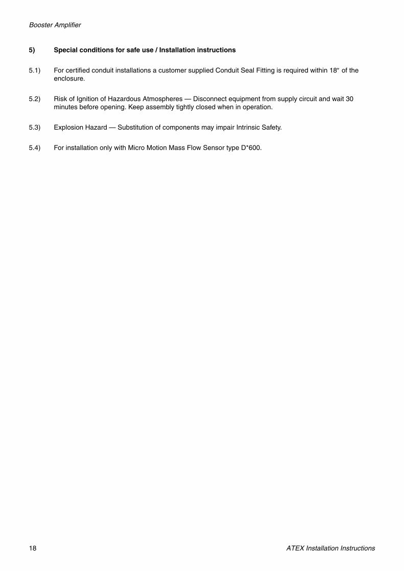
5) Special conditions for safe use / Installation instructions
5.1) For certified conduit installations a customer supplied Conduit Seal Fitting is required within 18″ of the enclosure.
5.2) Risk of Ignition of Hazardous Atmospheres — Disconnect equipment from supply circuit and wait 30 minutes before opening. Keep assembly tightly closed when in operation.
5.3) Explosion Hazard — Substitution of components may impair Intrinsic Safety.
5.4) For installation only with Micro Motion Mass Flow Sensor type D*600.

Booster Amplifier
ATEX Installation Instructions 19
Booster amplifier with core processor to D600 sensor
Allowable process fluid temperature range with remotely mounted booster amplifier is –194 °C < Tfluid < +87 °C for standard D600 sensor (EEx e Drive Coils). D600 Sensor
Equipment ground
This unit is provided with an external terminal for supplementary bonding connections. This terminal is for use
where local codes or authorities permit or require such connections.
Equipment ground
White
Green1/2″–14 NPT or
M20 × 1,5 adapter suppliedas ordered. Customer can wire through any port. Leave plugs
in unused ports.
For conduit installations:Conduit, seals, and wiring supplied by customer. Use single jacketed, twisted-pair, 18–14 gauge wire with insulation suitable for process and temperature. Conduit seal required within 18″ of enclosure. To be sealed after wiring. (customer supplied)
For cable installations:Use double jacketed, twisted-pair, minimum 18 gauge wire, with insulation suitable for process and temperature.
Maximum distance between remote booster amplifier and sensor is 18 m. Must be mechanically protected. See EN 60079-14 (cable only)
Intrinsically safe wiring. Shielded cable installed on booster amplifier by Micro Motion. Maximum distance between remote booster amplifier and sensor is 18 m.
Brown and red wires in supplied cable unused, insulated from contact with electrical components.
Intrinsically Safe EEx ib j-box
Violet
Yellow
Orange
Blue
Gray
Explosion-Proof/Flame-Proof EExd j-box
Do not open while energized. Wait 30 minutes after power is off before opening.
Seal
Installation method Fitting required
Per EN60079–14
Conduit EEx d IIB conduit seal
Cable EEx d IIB cable gland
Conduit or cable increased safety EEx e
Cable O.D. must be suitably sized to gland.
Conduit seal required within 18″ of enclosure. To be sealed after wiring. (customer supplied)
Power
Chassis ground
VAC
Remove screw and terminal cover prior towiring. Reinstall after wiring.
Connection diagram
From remote booster amp terminal
To sensor explosion-proof j-box terminal
1 1
2 2
Copper wire20–14 AWG
To achieve potential equalization the ground terminal must be connectedto the appropriate ground terminal within the hazardous area using a
potential equalizing line.Electronics: Booster amplifierSensor: D600
EB-1005122 Rev. D
1/2″–14 NPT or M20 × 1,5 adapter supplied as ordered
Allowable ambient temperature–40 °C < Tamb < +60 °C
Remote booster amplifier
To comply with the low voltage directive, install a power source switch near the Booster Amplifier.
Seal Seal
EExde [ib] IIB
Enclosures and interconnections are approved under ISSeP 04 ATEX 127 X
Enclosures and interconnections are approved under ISSeP 04 ATEX 127 X

Booster Amplifier
20 ATEX Installation Instructions
Booster amplifier with junction box to D600 sensor
Allowable process fluid temperature range with remotely mounted booster amplifier is –194 °C < Tfluid < +87 °C for standard D600 sensor (EEx e Drive Coils). D600 Sensor
Equipment ground
This unit is provided with an external terminal for supplementary bonding connections. This terminal is for use
where local codes or authorities permit or require such connections.
Equipment ground
White
Green1/2″–14 NPT or
M20 × 1,5 adapter suppliedas ordered. Customer can wire through any port. Leave plugs
in unused ports.
For conduit installations:Conduit, seals, and wiring supplied by customer. Use single jacketed, twisted-pair, 18–14 gauge wire with insulation suitable for process and temperature. Conduit seal required within 18″ of enclosure. To be sealed after wiring. (customer supplied)
For cable installations:Use double jacketed, twisted-pair, minimum 18 gauge wire, with insulation suitable for process and temperature.
Maximum distance between remote booster amplifier and sensor is 18 m. Must be mechanically protected. See EN 60079-14 (cable only)
Intrinsically safe wiring. Shielded cable installed on booster amplifier by Micro Motion. Maximum distance between remote booster amplifier and sensor is 18 m.
Brown and red wires in supplied cable unused, insulated from contact with electrical components.
Intrinsically Safe EEx ib j-box
Violet
Yellow
Orange
Blue
Gray
Explosion-Proof/Flame-Proof EExd j-box
Do not open while energized. Wait 30 minutes after power is off before opening.
Seal
Installation method Fitting required
Per EN60079–14
Conduit EEx d IIB conduit seal
Cable EEx d IIB cable gland
Conduit or cable increased safety EEx e
Cable O.D. must be suitably sized to gland.
Conduit seal required within 18″ of enclosure. To be sealed after wiring. (customer supplied)
Power
Chassis ground
VAC
Remove screw and terminal cover prior towiring. Reinstall after wiring.
Connection diagram
From remote booster amp terminal
To sensor explosion-proof j-box terminal
1 1
2 2
Copper wire20–14 AWG To achieve potential equalization the ground terminal must be
connected to the appropriate ground terminal within the hazardous area using a potential equalizing line.
Electronics: Booster amplifierSensor: D600
EB-3007062 Rev. D
1/2″–14 NPT or M20 × 1,5 adapter supplied as ordered
Allowable ambient temperature–40 °C < Tamb < +60 °C
Remote booster amplifier
To comply with the low voltage directive, install a power source switch near the Booster Amplifier.
Seal Seal
EExde [ib] IIB
Enclosures and interconnections are approved under ISSeP 04 ATEX 127 X
Enclosures and interconnections are approved under ISSeP 04 ATEX 127 X
21
Cable glands and adaptersATEX Installation Instructions
1) ATEX certification requirement
All sensor and transmitter cable glands and adapters are required to be ATEX certified. Refer to the specific manufacturer’s website for installation instructions.
ATEX Installation Instructions
Micro Motion Inc. USAWorldwide Headquarters7070 Winchester CircleBoulder, Colorado 80301T +1 303-527-5200
+1 800-522-6277F +1 303-530-8459
Micro Motion EuropeEmerson Process ManagementNeonstraat 16718 WX EdeThe NetherlandsT +31 (0) 318 495 555F +31 (0) 318 495 556
Micro Motion JapanEmerson Process Management1-2-5, Higashi ShinagawaShinagawa-kuTokyo 140-0002 JapanT +81 3 5769-6803F +81 3 5769-6844
Micro Motion AsiaEmerson Process Management1 Pandan CrescentSingapore 128461Republic of SingaporeT +65 6777-8211F +65 6770-8003
Micro Motion United KingdomEmerson Process Management LimitedHorsfield WayBredbury Industrial EstateStockport SK6 2SU U.K.T +44 0870 240 1978F +44 0800 966 181
©2007, Micro Motion, Inc. All rights reserved. P/N MMI-20010137, Rev. A
*MMI-20010137*
For the latest Micro Motion product specifications, view the PRODUCTS section of our web site at www.micromotion.com