
Micro machine tool oriented optimum design of 3-RPS ...
12
Bulletin of the JSME Journal of Advanced Mechanical Design, Systems, and Manufacturing Vol.11, No.3, 2017 Paper No.16-00600 © 2017 The Japan Society of Mechanical Engineers [DOI: 10.1299/jamdsm.2017jamdsm0035] Micro machine tool oriented optimum design of 3-RPS parallel mechanism with large titling and uniform deflecting capacities Gang ZHAO ∗ , Yang DENG ∗ , Wenlei XIAO ∗ and Yazui LIU ∗ ∗ School of Mechanical Engineering and Automation, Beihang University 37 Xueyuan Road, Haidian District, Beijing, 100191, China E-mail: [email protected] Abstract Parallel kinematic mechanism has shown its advantages as a high-precision motion stage in a machine tool. In this paper, a RPS-XY hybrid kinematic structure TRIPOD actuated by linear ultrasonic motors is proposed and designed for a five-axis ultra-precision micro machine tool. In the designing stage, both the titling capacity and the consistency of the deflecting abilities in all directions need to be carefully designed to overcome the platform’s limitation in the freeform surface machining. This study proposes an optimizer that can automatically search for a set of design parameters of the 3-RPS parallel part to generate large titling and uniform deflecting capacities simultaneously. A specified orientation workspace is calculated to evaluate the ability of rotation. Additionally, a new index is introduced to justify the uniform deflecting capacity. By evaluating those factors as the objective functions, a modified NSGA-II algorithm is employed for the optimum design with the consideration of discretely selected linear guides and spherical joints from a predefined database, which contains the abstracted engineering models of commercial products. Optimal results verify the feasibility and effectiveness of the proposed optimizer in designing a physical platform. The technique is extensible to most of other parallel mechanisms as a standard procedure. 1. Introduction tools. Generally, they have the advantages of high rigidity, low inertia, and high dynamics, whereas they also suffer from small workspace and limited flexibility (Huda and Takeda, 2007) (Koenigsberger and Tlusty, 2013). Recently, many design criteria have been proposed to evaluate the PKMs’ machining performance, such as workspace size, flexibility, etc. In order to balance those requests, the hybrid cooperating kinematics structure (HCKS) is frequently adopted in the application of five-axis machining (Li et al., 2007) (Shneor and Portman, 2010). However, its application in a micro machine tool is challenged due to the size limitation of components. Firstly, people usually wish to have a relatively large tilting angle for more freedoms in freeform machining, while the motion ranges of key components like linear guides and spherical joints are limited compared to their structural sizes. Secondly, in case of a limited orientation capability, only the minimum tilt angle (Shi et al., 2012) is not suffice to justify the freeform machining performance of a micro machine tool, as it is not able to represent the deflecting abilities in all directions (Wang et al., 2001). Actually, a large uniform deflecting capacity cannot only fasten the rapid motions, but also facilitate setup changes and reduce the machining lead- time (Hong and Kim, 2000). Thirdly, the critical components used in a micro machine tool are usually with high precision and great costs, thus their discrete structural parameters need to be carefully selected in the design, so as to make the most correct choice and avoid the risk of waste. In order to overcome the above difficulties, this paper develops an optimum design algorithm that can automatically search for a set of optimal parameters to design the parallel mechanism in a micro machine tool. 1 Key words : 3-RPS parallel mechanism, Micro machine tool, Five-axis machining, Rotational capacity, Multiobjective optimization Received: 2 November 2016; Revised: 7 July 2017; Accepted: 30 July 2017 Parallel Kinematic Mechanisms (PKMs) have been successfully used as high-precision motion stages in machine
Transcript of Micro machine tool oriented optimum design of 3-RPS ...

Bulletin of the JSME
Journal of Advanced Mechanical Design, Systems, and ManufacturingVol.11, No.3, 2017
Paper No.16-00600© 2017 The Japan Society of Mechanical Engineers[DOI: 10.1299/jamdsm.2017jamdsm0035]
Micro machine tool oriented optimum design of 3-RPS parallelmechanism with large titling and uniform deflecting capacities
Gang ZHAO∗, Yang DENG∗, Wenlei XIAO∗ and Yazui LIU∗∗ School of Mechanical Engineering and Automation, Beihang University
37 Xueyuan Road, Haidian District, Beijing, 100191, China
E-mail: [email protected]
AbstractParallel kinematic mechanism has shown its advantages as a high-precision motion stage in a machine tool. Inthis paper, a RPS-XY hybrid kinematic structure TRIPOD actuated by linear ultrasonic motors is proposed anddesigned for a five-axis ultra-precision micro machine tool. In the designing stage, both the titling capacity andthe consistency of the deflecting abilities in all directions need to be carefully designed to overcome the platform’slimitation in the freeform surface machining. This study proposes an optimizer that can automatically search fora set of design parameters of the 3-RPS parallel part to generate large titling and uniform deflecting capacitiessimultaneously. A specified orientation workspace is calculated to evaluate the ability of rotation. Additionally,a new index is introduced to justify the uniform deflecting capacity. By evaluating those factors as the objectivefunctions, a modified NSGA-II algorithm is employed for the optimum design with the consideration of discretelyselected linear guides and spherical joints from a predefined database, which contains the abstracted engineeringmodels of commercial products. Optimal results verify the feasibility and effectiveness of the proposed optimizerin designing a physical platform. The technique is extensible to most of other parallel mechanisms as a standardprocedure.
1. Introduction
tools. Generally, they have the advantages of high rigidity, low inertia, and high dynamics, whereas they also suffer fromsmall workspace and limited flexibility (Huda and Takeda, 2007) (Koenigsberger and Tlusty, 2013). Recently, manydesign criteria have been proposed to evaluate the PKMs’ machining performance, such as workspace size, flexibility,etc. In order to balance those requests, the hybrid cooperating kinematics structure (HCKS) is frequently adopted in theapplication of five-axis machining (Li et al., 2007) (Shneor and Portman, 2010). However, its application in a micromachine tool is challenged due to the size limitation of components. Firstly, people usually wish to have a relatively largetilting angle for more freedoms in freeform machining, while the motion ranges of key components like linear guides andspherical joints are limited compared to their structural sizes. Secondly, in case of a limited orientation capability, onlythe minimum tilt angle (Shi et al., 2012) is not suffice to justify the freeform machining performance of a micro machinetool, as it is not able to represent the deflecting abilities in all directions (Wang et al., 2001). Actually, a large uniformdeflecting capacity cannot only fasten the rapid motions, but also facilitate setup changes and reduce the machining lead-time (Hong and Kim, 2000). Thirdly, the critical components used in a micro machine tool are usually with high precisionand great costs, thus their discrete structural parameters need to be carefully selected in the design, so as to make the mostcorrect choice and avoid the risk of waste. In order to overcome the above difficulties, this paper develops an optimumdesign algorithm that can automatically search for a set of optimal parameters to design the parallel mechanism in a micromachine tool.
1
Key words : 3-RPS parallel mechanism, Micro machine tool, Five-axis machining, Rotational capacity, Multiobjective optimization
Received: 2 November 2016; Revised: 7 July 2017; Accepted: 30 July 2017
Parallel Kinematic Mechanisms (PKMs) have been successfully used as high-precision motion stages in machine
2© 2017 The Japan Society of Mechanical Engineers[DOI: 10.1299/jamdsm.2017jamdsm0035]
Zhao, Deng, Xiao and Liu, Journal of Advanced Mechanical Design, Systems, and Manufacturing, Vol.11, No.3 (2017)
In the last decades, amounts of researches have been implemented to optimize the rotational capacity in designing aPKM, in which the orientation workspace size and shape are the most frequently discussed and evaluated criteria. Kimet al. studied the machine tool workspace characteristics of the conventional Stewart-Gough platform with the maximumtilting angles 46◦ (ball joint range 55◦) (Kim et al., 2000). Li et al. proposed an optimized 3-RPS parallel A3 tool headwith the maximum nutation 40◦, the spherical joint of which is a combination of three revolute joints (Li et al., 2010). Liuet al. developed 3-DOF HANA, a spatial PKM using the kinematic chains of one PRU (the universal joint is substituted astwo revolute joints) and two PRPaR, and achieving high tilting capacity (±44.82◦) (Liu et al., 2005). Actually, the rangesof the tilting angles are limited by the corresponding critical joint capacities. Most of the above optimizations only involvethe maximum tilt capability, hence may result in non-regular shape of the orientation workspace. In the study by Shi etal. (2012), standard deviation was introduced to describe the oscillation between the maximum and minimum tilt angle,and the oscillation indicates the regularity of the shape of the workspace (defined as a circle). Wang et al. introduced avariable named the smallest reachable nutation angle to describe the conic face constraint of the workpiece orientation(Wang et al., 2001). Nonetheless, it is still hard to characterize the shape of the orientation workspace by those criteria.Furthermore, the structural parameters of a PKM stage are usually continuously derived, which may not fit the micromachine tool, as the structural parameters of some components behave discretely.
This paper proposes the design process of a 3-RPS stage (Hunt, 1983) used in a micro machine tool. An optimizationalgorithm is developed to fasten and optimize the design. Accordingly, this paper represents the orientation workspace ina new way, and a uniform deflection factor is proposed to quantify the deflecting consistency of the stage in all directions.Furthermore, design parameters of the stage are classified into two categories according to their engineering significance,based on which the effects of them on the rotational capacity are analyzed. Finally, by using a modified NSGA-II algorithmcapable of multi-objective optimization with mixed-discrete variables, the optimization is realized for large rotationalcapacity of 3-RPS PKM. With considering other important performance indexes, the optimal results can be conductedinto a physical stage.
2. Analysis of the orientation workspace
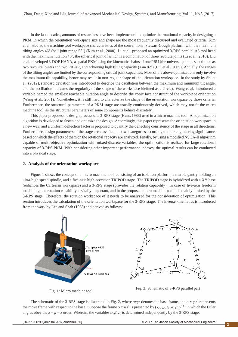
Figure 1 shows the concept of a micro machine tool, consisting of an isolation platform, a marble gantry holding anultra-high speed spindle, and a five-axis high-precision TRIPOD stage. The TRIPOD stage is hybridized with a XY base(enhances the Cartesian workspace) and a 3-RPS stage (provides the rotation capability). In case of five-axis freeformmachining, the rotation capability is vitally important, and in the proposed micro machine tool it is mainly limited by the3-RPS stage. Therefore, the rotation workspace of it needs to be analyzed for the consideration of optimization. Thissection introduces the calculation of the orientation workspace for the 3-RPS stage. The inverse kinematics is introducedfrom the work by Lee and Shah (1988) and derived as follows:
Fig. 1: Micro machine toolFig. 2: Schematic of 3-RPS parallel part
The schematic of the 3-RPS stage is illustrated in Fig. 2, whereoxyz denotes the base frame, ando′x′y′z′represents
the move frame with respect to the base. Suppose the frameo′x′y′z′is presented by (xc, yc, zc, α, β, γ)T , in which the Euler
angles obey thez − y − z order. Wherein, the variablesα, β, zc is determined independently by the 3-RPS stage.
2

2© 2017 The Japan Society of Mechanical Engineers[DOI: 10.1299/jamdsm.2017jamdsm0035]
Zhao, Deng, Xiao and Liu, Journal of Advanced Mechanical Design, Systems, and Manufacturing, Vol.11, No.3 (2017)
Correspondingly, the link lengths are calculated by:
L21 = R2 + r2 + x2
c + y2c + z2
c − 2Ryc + 2r(C2α +CβS
2α)(yc − R) + r(Cβ − 1)S 2αxc − 2rS αS βzc (1)
L22 =R2 + r2 + x2
c + y2c + z2
c + Ryc +√
3Rxc − r[S αCα(Cβ − 1)+√
3(C2αCβ + S 2
α)](xc +
√3
2R)
+ r[C2α +CβS
2α +√
3CαS α(Cβ − 1)](yc +12
R) + rS β(S α +√
3Cα)zc
(2)
L23 =R2 + r2 + x2
c + y2c + z2
c + Ryc −√
3Rxc − r[S αCα(Cβ − 1)−√
3(C2αCβ + S 2
α)](xc −√
32
R)
− r[C2α +CβS
2α −√
3CαS α(Cβ − 1)](yc +12
R) + rS β(S α −√
3Cα)zc
(3)
whereS α = sinα,Cα = cosα, S β = sinβ,Cβ = cosβ andS 2α = sin 2α.
2.1. Orientation workspaceThe orientation workspace is defined in a cylindrical coordinate system, which maps (α, β, zc) to (ρ, ϕ, z), and its
mapping relationship isρ = sinβ, ϕ = α andz = zc.
Fig. 3: Orientation workspace definition
As is shown in Fig. 3, the shape of the orientation workspace forms a quasi-hexahedron. Therefore, the plane atheight z = h0 intersects with the workspace and produces a shape asa → b → c → d → e → f . Due to the in-plane constraints from the revolute joints, the cylindrical coordinates of the three spherical joints are in fixed directionsof anglesϕ1 = −5π/6, ϕ2 = −π/6 andϕ3 = π/2. SupposingO
′is the center of the section, the radials in the directions
of ϕi(i = 1, 2, 3) intersect with the boundary atJi(i = 1, 2, 3), and the extensions ofJiO′(i = 1, 2, 3) intersect with the
boundary atJ′
i (i = 1, 2, 3). Obviously,Ji J′
i (i = 1, 2, 3) are the three symmetric lines of the section.According to the previous definitions, the orientation workspace can be obtained by summarizing the intersection
planes at different heightsz. Hence, an iterative algorithm has to be developed to numerically calculate the intersectionshapes by sampling the boundary coordinates in each direction. The searching steps are denoted as∆z and∆ϕ respectively.In addition, the computation costs can be significantly reduced by using the symmetry of the workspace, as only one-sixthof the intersection plane needs to be computed (Fig. 3).
Moreover, the calculation of boundary coordinates is the most computing consumed process, thus the bisectionalgorithm is employed to obtain a better efficiency:
1) Suppose in a direction of angleϕ, the interval within which to conduct the bisection process is set to [0,1]. Thus,the iterative process begins by settingρ(1) to the mid-point of the interval, i.e.,ρ(1) = 0.5.
2) By using the inverse kinematics, the lengths of linksL(1)i (i = 1, 2, 3) and the angles of swing of spherical joints
ψ(1)i (i = 1, 2, 3) can be calculated. IfLmin ≤ L(1)
i ≤ Lmax and−ψmax ≤ ψ(1)i ≤ ψmax, thenρ(2) is chosen to be the mid-point
of the interval [ρ(1), 1]. Otherwise,ρ(2) is chosen to be the mid-point of the interval [0, ρ(1)].3) The above process is repeated until|ρ(k) − ρ(k−1)| < ερ, hence the final valueρ(k) indicates the boundary in this
direction.
3
2© 2017 The Japan Society of Mechanical Engineers[DOI: 10.1299/jamdsm.2017jamdsm0035]
Zhao, Deng, Xiao and Liu, Journal of Advanced Mechanical Design, Systems, and Manufacturing, Vol.11, No.3 (2017)
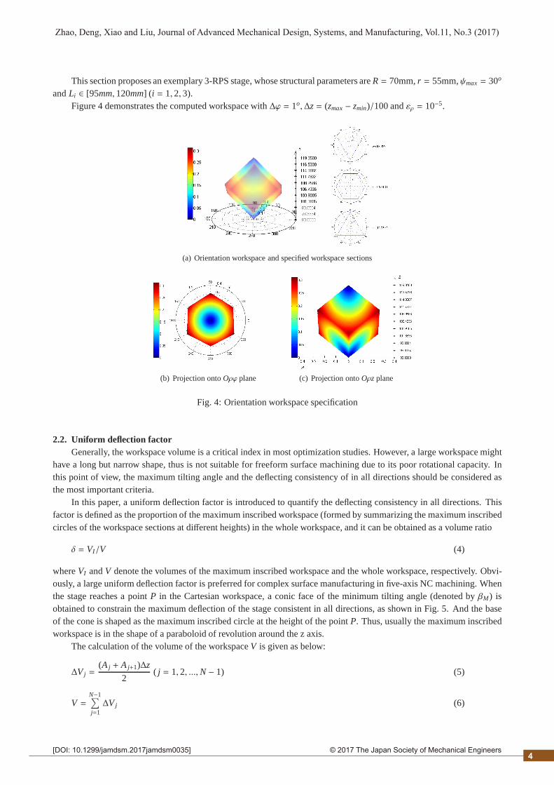
This section proposes an exemplary 3-RPS stage, whose structural parameters areR = 70mm,r = 55mm,ψmax = 30o
andLi ∈ [95mm, 120mm] (i = 1, 2, 3).Figure 4 demonstrates the computed workspace with∆ϕ = 1o,∆z = (zmax − zmin)/100 andερ = 10−5.
(a) Orientation workspace and specified workspace sections
(b) Projection ontoOρϕ plane (c) Projection ontoOρz plane
Fig. 4: Orientation workspace specification
2.2. Uniform deflection factorGenerally, the workspace volume is a critical index in most optimization studies. However, a large workspace might
have a long but narrow shape, thus is not suitable for freeform surface machining due to its poor rotational capacity. Inthis point of view, the maximum tilting angle and the deflecting consistency of in all directions should be considered asthe most important criteria.
In this paper, a uniform deflection factor is introduced to quantify the deflecting consistency in all directions. Thisfactor is defined as the proportion of the maximum inscribed workspace (formed by summarizing the maximum inscribedcircles of the workspace sections at different heights) in the whole workspace, and it can be obtained as a volume ratio
δ = VI/V (4)
whereVI andV denote the volumes of the maximum inscribed workspace and the whole workspace, respectively. Obvi-ously, a large uniform deflection factor is preferred for complex surface manufacturing in five-axis NC machining. Whenthe stage reaches a pointP in the Cartesian workspace, a conic face of the minimum tilting angle (denoted byβM) isobtained to constrain the maximum deflection of the stage consistent in all directions, as shown in Fig. 5. And the baseof the cone is shaped as the maximum inscribed circle at the height of the pointP. Thus, usually the maximum inscribedworkspace is in the shape of a paraboloid of revolution around the z axis.
The calculation of the volume of the workspaceV is given as below:
∆V j =(A j + A j+1)∆z
2( j = 1, 2, ...,N − 1) (5)
V =N−1∑
j=1∆V j (6)
4

2© 2017 The Japan Society of Mechanical Engineers[DOI: 10.1299/jamdsm.2017jamdsm0035]
Zhao, Deng, Xiao and Liu, Journal of Advanced Mechanical Design, Systems, and Manufacturing, Vol.11, No.3 (2017)
Fig. 5: Schematic of the uniform deflecting of the stage
whereN is the number of iterations in thez axis, andA j is the area of thejth workspace section obtained by
A j =K−1∑
s=1
(ρs + ρs+1)∆ϕ4
(s = 1, 2, ...,K − 1) (7)
in which K is the number of iterations in the direction, andρs denotes the boundary in thesth direction.Similarly, the volume of the maximum inscribed worksp-aceVI can also be calculated. And, the uniform deflection
factor can be determined by Eq. (4).
3. Continuous and discrete parameters
The engineering assembly model of 3-RPS stage is given in Fig. 6, whose structural and dimensional parameters aregiven in Fig. 7, Fig. 8, and Fig. 9.
Fig. 6: Engineering assembly model of 3-RPS parallelmechanism
Fig. 7: Mounting configuration of the spherical joint
3.1. Engineering definition of parametersIn the engineering optimum design, critical parameters need to be considered and redefined according to their en-
gineering significance. These parameters can be categorized as continuous and discrete. The continuous parameters arestructural variables that can be continuously customized, which include the radii of the moving and base platforms (r,R),the heights of the moving and base platforms (h,H) (Fig. 6), the mounting angle of the spherical jointζ (Fig. 7), and thecustomizable lengths of the linkS 1, S 2, S 3 (Fig. 9(a)). The discrete parameters are derived from the standard commercial-ized components (i.e., the linear guideM1 and the spherical jointM2, as shown in Fig. 6) and thus can only be optimizedas discrete variables. In this study, the cross roller guide model (VR series) from THK and the spherical rolling joint (SRJseries) from HEPHAIST SEIKO are chosen. Accordingly, the discrete parameters include the original rail lengthL0, thestopper sicknessT , the maximum strokeP (Fig. 8(a)), and the permissible angle of swingψmax, the length of axis of
5
2© 2017 The Japan Society of Mechanical Engineers[DOI: 10.1299/jamdsm.2017jamdsm0035]
Zhao, Deng, Xiao and Liu, Journal of Advanced Mechanical Design, Systems, and Manufacturing, Vol.11, No.3 (2017)
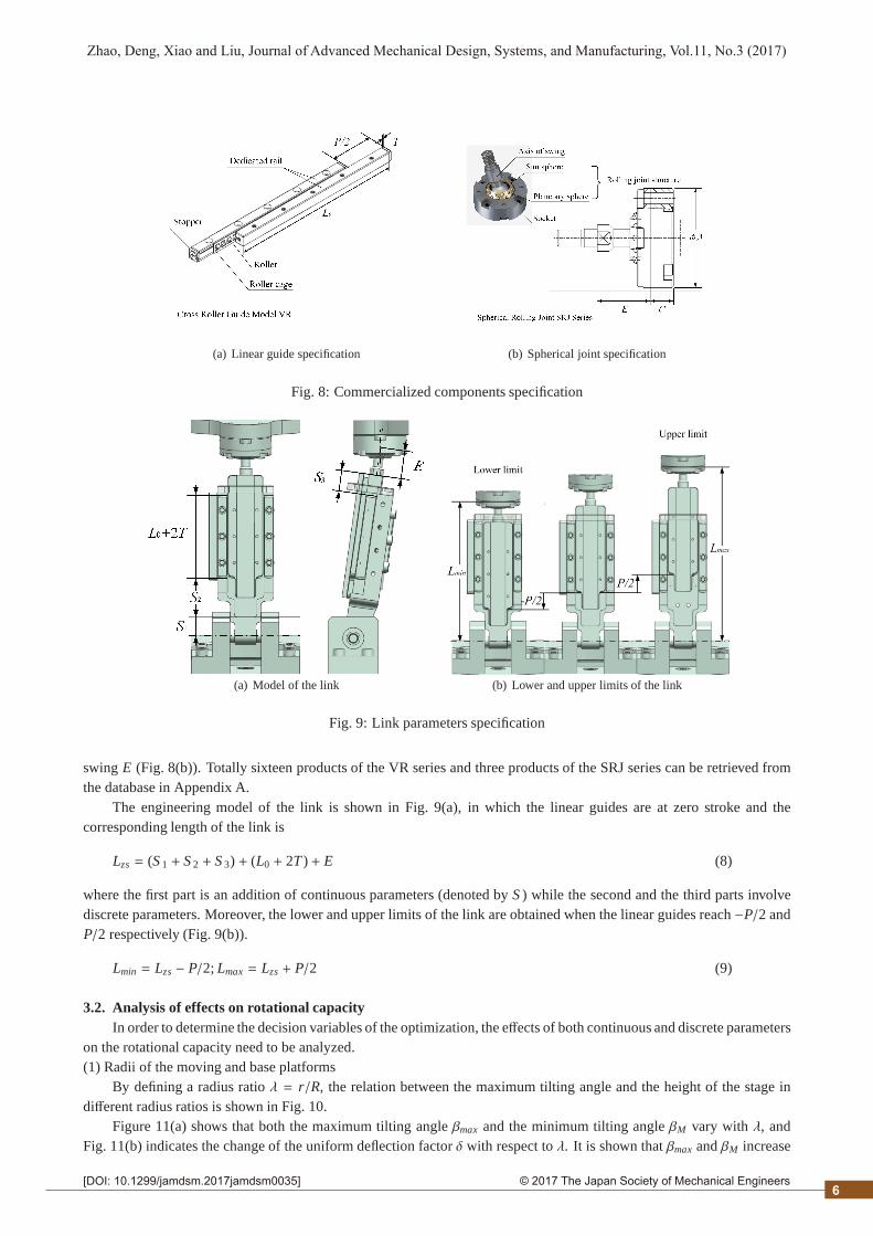
(a) Linear guide specification (b) Spherical joint specification
Fig. 8: Commercialized components specification
(a) Model of the link (b) Lower and upper limits of the link
Fig. 9: Link parameters specification
swingE (Fig. 8(b)). Totally sixteen products of the VR series and three products of the SRJ series can be retrieved fromthe database in Appendix A.
The engineering model of the link is shown in Fig. 9(a), in which the linear guides are at zero stroke and thecorresponding length of the link is
Lzs = (S 1 + S 2 + S 3) + (L0 + 2T ) + E (8)
where the first part is an addition of continuous parameters (denoted byS ) while the second and the third parts involvediscrete parameters. Moreover, the lower and upper limits of the link are obtained when the linear guides reach−P/2 andP/2 respectively (Fig. 9(b)).
Lmin = Lzs − P/2; Lmax = Lzs + P/2 (9)
3.2. Analysis of effects on rotational capacityIn order to determine the decision variables of the optimization, the effects of both continuous and discrete parameters
on the rotational capacity need to be analyzed.(1) Radii of the moving and base platforms
By defining a radius ratioλ = r/R, the relation between the maximum tilting angle and the height of the stage indifferent radius ratios is shown in Fig. 10.
Figure 11(a) shows that both the maximum tilting angleβmax and the minimum tilting angleβM vary with λ, andFig. 11(b) indicates the change of the uniform deflection factorδ with respect toλ. It is shown thatβmax andβM increase
6

2© 2017 The Japan Society of Mechanical Engineers[DOI: 10.1299/jamdsm.2017jamdsm0035]
Zhao, Deng, Xiao and Liu, Journal of Advanced Mechanical Design, Systems, and Manufacturing, Vol.11, No.3 (2017)
Fig. 10: Maximum tilting angles in different radius ratios
firstly then decrease with the increase ofλ and attend their extremes simultaneously whenλ = 0.7. And, δ is almostconstant asλ ranges from 0.8 to 1.6.
(a) Maximum and minimum tilting angles in different radiusratios
(b) Uniform deflection factors in different radius ratios
Fig. 11: Effects of radius ratio on rotational capacity
(2) Heights of the moving and base platformsWith the increase ofh and H, the points in the workspace are lifted in the positivez axis. However, the lifting
mechanism byh is different from that byH, for the latter one is an equal-distance lifting for the coordinates of all thepoints while the former one (Fig. 12) is not.
As shown in the figure, the center of the section possesses the lifting distance ofh (P0 → P′
0,∆z0 = h), and a largernutation angleβ means a smaller lifting distance (P2 versusP1, ∆z0 cosβ2 < ∆z0 cosβ1). Obviously, the mechanismdoes not change the maximum tilting angle. Furthermore, the volume of the sub-workspace formed by thejth workspacesectionV
′
j can be calculated by double integrating in the polar coordinates
∆V′
j =
"ρdρdϕcosβ
· ∆z cosβ = ∆z"
ρdρdϕ = ∆V j (10)
It is suggested that the sub-workspace is with its original volumeV j, and the volume of the whole workspace staysthe same. Thus, the mechanism does not change the uniform deflection factor either. In conclusion, bothh andH have noeffects on the rotational capacity.(3) Mounting angle of the spherical joint
Obviously, the rotation of the link about the spherical joint is constrained by the mounting angle of the joint anddetermined by the workspace. In this sense, the effect of the mounting angle on workspace can be analyzed in two steps:
7
2© 2017 The Japan Society of Mechanical Engineers[DOI: 10.1299/jamdsm.2017jamdsm0035]
Zhao, Deng, Xiao and Liu, Journal of Advanced Mechanical Design, Systems, and Manufacturing, Vol.11, No.3 (2017)
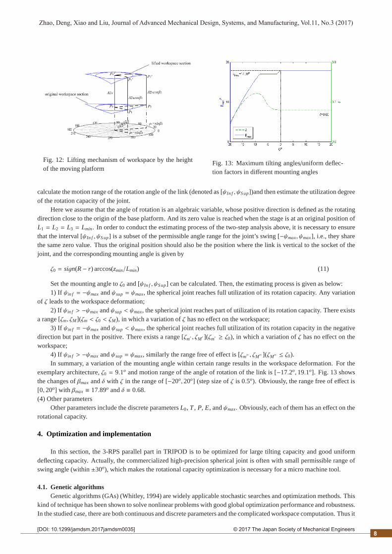
Fig. 12: Lifting mechanism of workspace by the heightof the moving platform
Fig. 13: Maximum tilting angles/uniform deflec-tion factors in different mounting angles
calculate the motion range of the rotation angle of the link (denoted as [ψIn f , ψS up])and then estimate the utilization degreeof the rotation capacity of the joint.
Here we assume that the angle of rotation is an algebraic variable, whose positive direction is defined as the rotatingdirection close to the origin of the base platform. And its zero value is reached when the stage is at an original position ofL1 = L2 = L3 = Lmin. In order to conduct the estimating process of the two-step analysis above, it is necessary to ensurethat the interval [ψIn f , ψS up] is a subset of the permissible angle range for the joint’s swing [−ψmax, ψmax], i.e., they sharethe same zero value. Thus the original position should also be the position where the link is vertical to the socket of thejoint, and the corresponding mounting angle is given by
ζ0 = sign(R − r) arccos(zmin/Lmin) (11)
Set the mounting angle toζ0 and [ψIn f , ψS up] can be calculated. Then, the estimating process is given as below:1) If ψin f = −ψmax andψsup = ψmax, the spherical joint reaches full utilization of its rotation capacity. Any variation
of ζ leads to the workspace deformation;2) If ψin f > −ψmax andψsup < ψmax, the spherical joint reaches part of utilization of its rotation capacity. There exists
a range [ζm, ζM](ζm < ζ0 < ζM), in which a variation ofζ has no effect on the workspace;3) If ψin f = −ψmax andψsup < ψmax, the spherical joint reaches full utilization of its rotation capacity in the negative
direction but part in the positive. There exists a range [ζm′ , ζM′ ](ζm′ ≥ ζ0), in which a variation ofζ has no effect on theworkspace;
4) If ψin f > −ψmax andψsup = ψmax, similarly the range free of effect is [ζm′′ , ζM′′ ](ζM′′ ≤ ζ0).In summary, a variation of the mounting angle within certain range results in the workspace deformation. For the
exemplary architecture,ζ0 = 9.1o and motion range of the angle of rotation of the link is [−17.2o, 19.1o]. Fig. 13 showsthe changes ofβmax andδ with ζ in the range of [−20o, 20o] (step size ofζ is 0.5o). Obviously, the range free of effect is[0, 20o] with βmax ≡ 17.89o andδ ≡ 0.68.(4) Other parameters
Other parameters include the discrete parametersL0, T , P, E, andψmax. Obviously, each of them has an effect on therotational capacity.
4. Optimization and implementation
In this section, the 3-RPS parallel part in TRIPOD is to be optimized for large tilting capacity and good uniformdeflecting capacity. Actually, the commercialized high-precision spherical joint is often with small permissible range ofswing angle (within±30o), which makes the rotational capacity optimization is necessary for a micro machine tool.
4.1. Genetic algorithmsGenetic algorithms (GAs) (Whitley, 1994) are widely applicable stochastic searches and optimization methods. This
kind of technique has been shown to solve nonlinear problems with good global optimization performance and robustness.In the studied case, there are both continuous and discrete parameters and the complicated workspace computation. Thus it
8
2© 2017 The Japan Society of Mechanical Engineers[DOI: 10.1299/jamdsm.2017jamdsm0035]
Zhao, Deng, Xiao and Liu, Journal of Advanced Mechanical Design, Systems, and Manufacturing, Vol.11, No.3 (2017)
is very hard to figure out the analytical expressions of the objective functions. Moreover, for other optimization techniques,only a few geometric parameters (Gosselin and Guillot, 1991) can be handled for the lack of convergence in such complexproblems. Hence, the genetic algorithm is the best candidate.
To obtain the non-dominated solutions of the current case, the NSGA-II algorithm proposed by Deb et al. (2002)which is the most preferred algorithm to solve the multi-objective problems based on the principles of GA, is adopted.
4.2. Decision variablesThe radius ratioλ, the customizable length of the linkS , the mounting angle of the spherical jointζ, the discrete
parameters (L0, T, P) from the linear guide and (E, ψmax) from the spherical joint, are chosen as the decision variables.Non-negative integers representing the products ofM1 andM2, is used to substitute (L0, T, P) and (E, ψmax) as the decisionvariables. The vector of decision variables is
x = (λ, S , ζ, M1, M2)T (12)
and their bounds or values are shown as below
Table 1: Bounds or values of the decision variables
λ S (mm) ζ(o) M1 M2
0.5 ∼ 1.5 10∼ 200 −30∼ 30 0, 1, ..., 15 0, 1, 2
4.3. GA parameters setupThe standard NSGA-II algorithm was designed for continuous variables without constraints, thus is not suitable for
the current case and cannot be directly used. The parameters and corresponding modifications are:Chromosome representation: Real number representation in the standard algorithm cannot support the coding of the
discrete variables, while binary representation and Gray code representation can. Moreover, Gray coding improves thesearch efficiency compared with binary coding. Thus, Gary code representation is employed with the coding precision setto 10−4 mm(rad);
Selection function: Tournament selection process in the standard algorithm is preserved;Genetic operators: Employ fixed-probability uniform crossover withpc = 0.9 and simple mutation withpm = 0.1 as
the genetic operators for a high efficiency in processing the Gray-coded chromosome;Population size: Population size is set to 20;Evaluation function: Each evaluation function consists of two parts, an objective function modeled by a analytic
hierarchy process (Chang, 1996), and an adaptive penalty function.In the modeling of the objective functions, two secondary criteria are considered: the radius ratioλ to ensure that the
worktable should not be too small, and the motion range of the revolute joint (denoted by∆φ) to ensure its compatibilitywith the flexible hinge. And compared with them, both the two major indexesβmax andδ are on the level of apparentlysignificant, based on which the weight vector is figured out as (0.9623, 0.1925, 0.1925)T. Thus, the objective functionsare
f1(x) = 0.9623f01(x) + 0.1925g1(x) + 0.1925g2(x) (13)
f2(x) = 0.9623f02(x) + 0.1925g1(x) + 0.1925g2(x) (14)
in which f01(x) = 1− βmax and f02(x) = 1− δ. g1(x) andg2(x) areλ related and∆φ related functions, respectively.
∆φ = acrcos(|R − r|/Lmax) − arccos(|R − r|/Lmin) (15)
The two evaluation functions are (Liu and Zhou, 2006)
fpi(x) = fi(x) +Ci(x) · p(x) (i = 1, 2) (16)
where the coefficientCi(x) is given by
Ci(x) = 1+ | fi(x)|/[1 + p(x)] (i = 1, 2) (17)
9
2© 2017 The Japan Society of Mechanical Engineers[DOI: 10.1299/jamdsm.2017jamdsm0035]
Zhao, Deng, Xiao and Liu, Journal of Advanced Mechanical Design, Systems, and Manufacturing, Vol.11, No.3 (2017)
In conclusion, the optimization is formulated as:
min fpi(x) (i = 1, 2)
subject to:• R = 100, 0.5≤ λ ≤ 1.5, 10≤ S ≤ 200,−30o ≤ ζ ≤ 30o;• M1 = {0, 1, 2, ..., 15}, M2 = {0, 1, 2};• Lmin ≥ max{R, r}, Lmax ≤ 2.5 max{R, r}, S ≥ P + S In f .
where the constraints are established to ensure a reasonable mechanism dimension and avoid components interference.
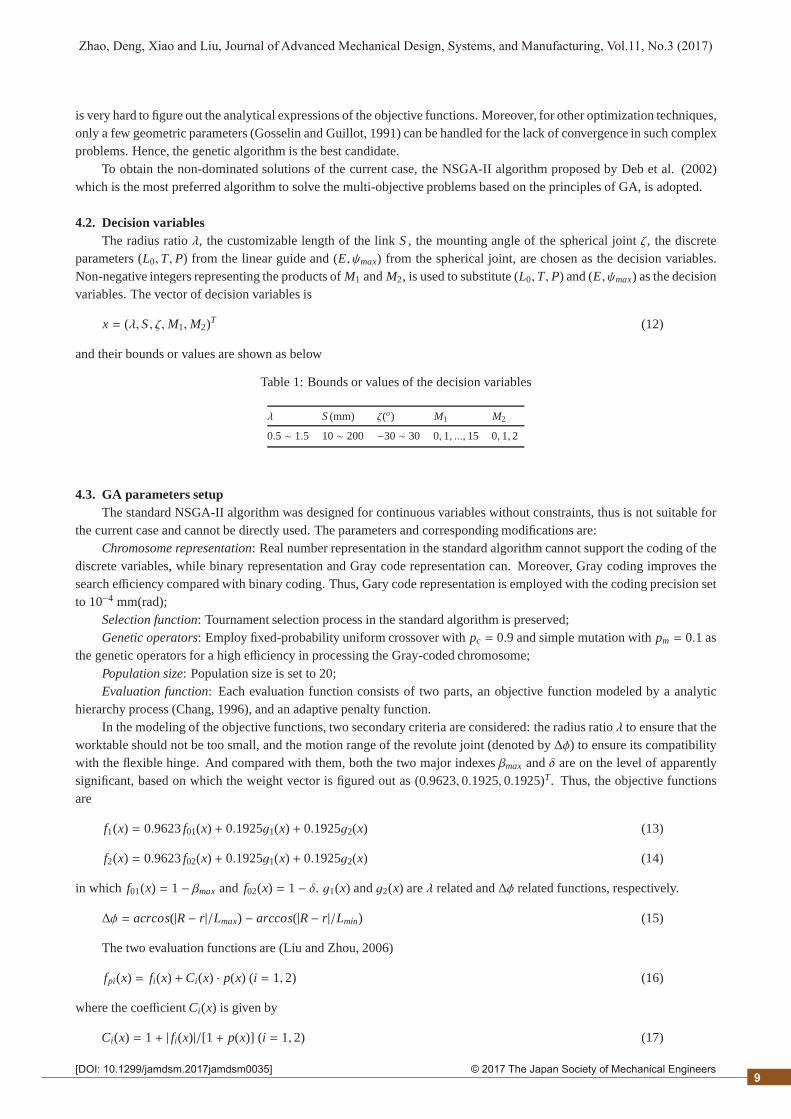
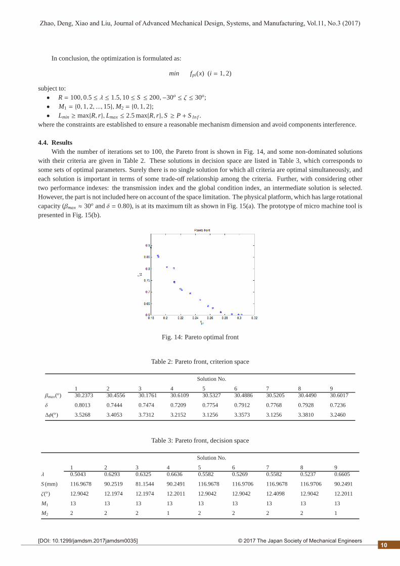
4.4. ResultsWith the number of iterations set to 100, the Pareto front is shown in Fig. 14, and some non-dominated solutions
with their criteria are given in Table 2. These solutions in decision space are listed in Table 3, which corresponds tosome sets of optimal parameters. Surely there is no single solution for which all criteria are optimal simultaneously, andeach solution is important in terms of some trade-off relationship among the criteria. Further, with considering othertwo performance indexes: the transmission index and the global condition index, an intermediate solution is selected.However, the part is not included here on account of the space limitation. The physical platform, which has large rotationalcapacity (βmax ≈ 30o andδ = 0.80), is at its maximum tilt as shown in Fig. 15(a). The prototype of micro machine tool ispresented in Fig. 15(b).
Fig. 14: Pareto optimal front
Table 2: Pareto front, criterion space
Solution No.
1 2 3 4 5 6 7 8 9βmax(o) 30.2373 30.4556 30.1761 30.6109 30.5327 30.4886 30.5205 30.4490 30.6017
δ 0.8013 0.7444 0.7474 0.7209 0.7754 0.7912 0.7768 0.7928 0.7236
∆φ(o) 3.5268 3.4053 3.7312 3.2152 3.1256 3.3573 3.1256 3.3810 3.2460
Table 3: Pareto front, decision space
Solution No.
1 2 3 4 5 6 7 8 9λ 0.5043 0.6293 0.6325 0.6636 0.5582 0.5269 0.5582 0.5237 0.6605
S (mm) 116.9678 90.2519 81.1544 90.2491 116.9678 116.9706 116.9678 116.9706 90.2491
ζ(o) 12.9042 12.1974 12.1974 12.2011 12.9042 12.9042 12.4098 12.9042 12.2011
M1 13 13 13 13 13 13 13 13 13
M2 2 2 2 1 2 2 2 2 1
10

2© 2017 The Japan Society of Mechanical Engineers[DOI: 10.1299/jamdsm.2017jamdsm0035]
Zhao, Deng, Xiao and Liu, Journal of Advanced Mechanical Design, Systems, and Manufacturing, Vol.11, No.3 (2017)
5. Conclusion
In this study, micro machine tool oriented optimization of 3-RPS PKM is presented. A RPS-XY hybrid kinematicstructure TRIPOD is proposed and designed for ultra-precision five-axis manufacturing. A newly represented orientationworkspace is analyzed and calculated. The deflecting consistency of the stage in all directions, which determines thecontinuity and efficiency of manufacturing, is quantified by a new index. Moreover, structural and dimensional param-eters of 3-RPS PKM are categorized as continuous and discrete, based on which their effects on rotational capacity areinvestigated. At last, by using a modified NSGA-II algorithm, an optimizer is established to design the stage.
(a) The physical stage (b) The prototype of micro machine tool
Fig. 15: The physical stage and prototype of micro machine tool
Acknowledgements
The authors would like to acknowledge the support of National Natural Science Foundation of China. (Project No.:51505020)
Appendix A.
The database of products of THK Cross Roller Guide (Table A1) and HEPHAIST SEIKO Spherical Rolling Joint(Table A2)
References
Chang, D. Y., Applications of the extent analysis method on fuzzy AHP, European journal of operational research, Vol.95,No.3 (1996), pp.649-655.
Deb, K., Pratap, A., Agarwal, S., and Meyarivan, T., A fast and elitist multiobjective genetic algorithm: NSGA-II, IEEETransactions on Evolutionary Computation, Vol.6, No.2 (2002), pp.182-197.
Gosselin, C. M. and Guillot, M., The synthesis of manipulators with prescribed workspace, Journal of Mechanical Design,Vol.113, No.4 (1991), pp.451-455.
Hong, K. S. and Kim, J. G., Manipulability analysis of a parallel machine tool: application to optimal link length design,Journal of Robotic Systems, Vol.17, No.8 (2000), pp.403-415.
Huda, S. and Takeda, Y., Kinematic Analysis and Synthesis of a 3-URU Pure Rotational Parallel Mechanism with Respectto Singularity and Workspace, Journal of Advanced Mechanical Design Systems & Manufacturing, Vol.1, No.1(2007), pp.81-92.
Hunt K. H., Structural kinematics of in-parallel-actuated robot-arms, Journal of Mechanical Design, Vol.105, No.4 (1983),pp.705-712.
Kim, J., Park, C., Kim, J. and Park, F. C., Performance analysis of parallel mechanism architectures for CNC machiningapplications, Journal of manufacturing science and engineering, Vol.122, No.4 (2000), pp.753-759.
11

2© 2017 The Japan Society of Mechanical Engineers[DOI: 10.1299/jamdsm.2017jamdsm0035]
Zhao, Deng, Xiao and Liu, Journal of Advanced Mechanical Design, Systems, and Manufacturing, Vol.11, No.3 (2017)
Table A1: Linear guide modelM1
M1 Product Model P(mm) L0(mm) T (mm)
0 VR1-20×5Z 12 20 1.6
1 VR2-30×5Z 18 30 1.5
2 VR1-30×7Z 22 30 1.6
3 VR1-40×10Z 27 40 1.6
4 VR2-45×8Z 24 45 1.5
5 VR1-50×13Z 32 50 1.6
6 VR3-50×7Z 28 50 2
7 VR2-60×11Z 30 60 1.5
8 VR1-60×16Z 37 60 1.6
9 VR1-70×19Z 42 70 1.6
10 VR2-75×13Z 44 75 1.5
11 VR3-75×10Z 48 75 2
12 VR1-80×21Z 52 80 1.6
13 VR4-80×7Z 58 80 2
14 VR2-90×16Z 50 90 1.5
15 VR3-100×14Z 58 100 2
Table A2: Spherical joint modelM2
M2 Product Model A,C, E(mm) ψmax(o)
0 SRJ006C 25,5.5,11.5 30
1 SRJ008C 30,7,16 30
2 SRJ012C 42,11,20 30
Koenigsberger, F. and Tlusty, J., Machine tool structures (2013), Elsevier.Lee K. M. and Shah D. K., Kinematic analysis of a three-degrees-of-freedom in-parallel actuated manipulator, Journal of
Robotics and Automation, Vol.4, No.3 (1988), pp.354-360.Li, Y. G., Liu, H. T., Zhao, X. M., Huang, T. and Chetwynd, D. G., Design of a 3-DOF PKM module for large structural
component machining, Mechanism & Machine Theory, Vol.45, No.6 (2010), pp.941-954.Li, B., Yang, X., Hu, Y., Wang, Y. and Zhao, J., Dynamic Modeling and Design for the Parallel Mechanism of a Hybrid
Type Parallel Kinematic Machine, Journal of Advanced Mechanical Design Systems & Manufacturing, Vol.1, No.4(2007), pp.481-492.
Liu, X. J., Tang, X., Wang, J., Huang, T. and Chetwynd, D. G., HANA: a novel spatial parallel manipulator with onerotational and two translational degrees of freedom, Robotica, Vol.23, No.2 (2005), pp.257-270.
Liu, Q. and Zhou, S., Hybrid genetic algorithm based on novel adaptive penalty function, Journal of Chongqing University(Natural Science Edition) (in Chinese), Vol.6, No.29 (2006), pp.78-81.
Shi, J., Wang Y. H., Zhang G., and Ding, H., Optimal design of 3-DOF PKM module for friction stir welding, InternationalJournal of Advanced Manufacturing Technology, Vol.66, No.9-12 (2012), pp.1879-1889.
Shneor, Y. and Portman, V. T., Stiffness of 5-axis machines with serial, parallel, and hybrid kinematics: evaluation andcomparison, CIRP Annals-Manufacturing Technology, Vol.59, No.1 (2010), pp.409-412.
Wang, Z., Wang, Z., Liu, W. and Lei, Y., A study on workspace, boundary workspace analysis and workpiece positioningfor parallel machine tools, Mechanism & Machine Theory, Vol.36, No.5 (2001), pp.605-622.
Whitley, D., A genetic algorithm tutorial, Statistics and computing, Vol.4, No.2 (1994), pp.65-85.
12