Micro (and Nano-) Mechanical Signal Processors · Micro (and Nano-) Mechanical Signal Processors...
6
Micro (and Nano-) Mechanical Signal Processors Sunil A. Bhave OxideMEMS Lab, Electrical and Computer Engineering, Cornell University, Ithaca, NY 14853 ABSTRACT With quality factors (Q) often-exceeding 10,000, vibrating micromechanical resonators have emerged as leading candidates for on-chip versions of high-Q resonators used in wireless communications systems. However, as in the case for transistors, extending the frequency of MEMS resonators generally entails scaling of resonator dimensions. Unfortunately, smaller size often coincides with lower-power handling capability and increased motional impedance. In this paper we introduce novel transduction techniques which can improve the motional impedance of MEMS resonators by 1000× over traditional 'air-gap' transduced resonators, present latest results on narrow-bandwidth parametric filters for frequency-agile radio receivers, and discuss performance scaling of NEMS resonators to X-band frequencies. Keywords: RF MEMS, resonators, dielectric transduction, quality factor 1. INTRODUCTION Maturity in micro-electro-mechanical systems (MEMS) fabrication technology has opened the opportunity to design high quality factor (Q) mechanically-coupled micromechanical structures capable of implementing ultra-low-power frequency-domain signal processing functions. We endeavor to demonstrate new and high-impact micro-electro- mechanical circuits using such mechanically-linked networks. In the OxideMEMS Lab we have invented new mechanical designs and efficient transducers to manufacture MEMS resonators with high resonance frequency, low motional impedance, strong transducer coupling coefficient, low bias drift and large tuning range. We characterized and cataloged these resonators, developed and verified butterworth van-dyke (BVD) resonator models, investigated their coupling mechanisms to demonstrate channel-select filters, and explored inter-domain coupling to design merged resonant body transistors. 2. DIELECTRICALLY TRANSDUCED RESONATORS AND FILTERS Modern wireless transceivers are designed under a mandate to minimize the use of off-chip passive devices. However, the increasingly-crowded radio spectrum and the impending arrival of next generation 7-band cellular phone and the joint task force radio system (JTRS) has necessitated front-end filters capable of eliminating both out-of-band and out- of-channel interferers. Such channel-select filters will also relax the dynamic range requirements of the LNA and the phase noise requirements of the local oscillators, leading to a 10× reduction in power consumption of direct-conversion radio receivers. Building of initial pioneering work at Berkeley and Delft, we demonstrated solid-dielectric transduced thickness shear mode MEMS resonators with 807 MHz center frequency, motional impedance R X < 100: and Q’s > 7,000 [1]. We have developed ‘orthogonal frequency tuning’ technique for independently changing the series and parallel resonant frequencies of dielectrically transduced thickness shear mode resonators. Using this technique our channel-select filter array is capable of dynamically tuning center frequency and filter bandwidth, thereby reducing capacitive loading at the filter input. This enables reception of multiple waveforms, and leads to substantial reduction in the number of filters in next-generation frequency-agile transceivers [2]. The thickness shear mode resonators have high Q and low R X . However, their second-order dependence on CAD- defined dimensions severely limits the frequency design space. Contour-mode resonators can be designed across a much wider frequency range but have minimal tuning capability [3]. We have invented, designed and demonstrated a digital tuning technique for a filter consisting of mechanically coupled contour-mode resonators. By altering the polarization voltage applied to each resonator in the array we can digitally change the filter center frequency and alter the bandwidth from 1.4 MHz to 700 kHz (Figure 1) [4]. Unlike the analog voltage tunable shear-mode filters, the digitally-tunable filters are significantly less sensitive to variations and noise on the DC polarization voltage. We also proposed and demonstrated a 2D filter arraying technique to make the filters less susceptible to process variations [5]. We worked with Invited Paper Micro- and Nanotechnology Sensors, Systems, and Applications II, edited by Thomas George, M. Saif Islam, Achyut K. Dutta, Proc. of SPIE Vol. 7679, 76790J · © 2010 SPIE · CCC code: 0277-786X/10/$18 · doi: 10.1117/12.849296 Proc. of SPIE Vol. 7679 76790J-1 Downloaded from SPIE Digital Library on 11 Mar 2012 to 132.236.27.111. Terms of Use: http://spiedl.org/terms
Transcript of Micro (and Nano-) Mechanical Signal Processors · Micro (and Nano-) Mechanical Signal Processors...

Micro (and Nano-) Mechanical Signal ProcessorsSunil A. Bhave
OxideMEMS Lab, Electrical and Computer Engineering, Cornell University, Ithaca, NY 14853
ABSTRACT
With quality factors (Q) often-exceeding 10,000, vibrating micromechanical resonators have emerged as leading candidates for on-chip versions of high-Q resonators used in wireless communications systems. However, as in the case for transistors, extending the frequency of MEMS resonators generally entails scaling of resonator dimensions. Unfortunately, smaller size often coincides with lower-power handling capability and increased motional impedance. In this paper we introduce novel transduction techniques which can improve the motional impedance of MEMS resonators by 1000× over traditional 'air-gap' transduced resonators, present latest results on narrow-bandwidth parametric filters for frequency-agile radio receivers, and discuss performance scaling of NEMS resonators to X-band frequencies.
Keywords: RF MEMS, resonators, dielectric transduction, quality factor
1. INTRODUCTION Maturity in micro-electro-mechanical systems (MEMS) fabrication technology has opened the opportunity to design high quality factor (Q) mechanically-coupled micromechanical structures capable of implementing ultra-low-power frequency-domain signal processing functions. We endeavor to demonstrate new and high-impact micro-electro-mechanical circuits using such mechanically-linked networks. In the OxideMEMS Lab we have invented new mechanical designs and efficient transducers to manufacture MEMS resonators with high resonance frequency, low motional impedance, strong transducer coupling coefficient, low bias drift and large tuning range. We characterized and cataloged these resonators, developed and verified butterworth van-dyke (BVD) resonator models, investigated their coupling mechanisms to demonstrate channel-select filters, and explored inter-domain coupling to design merged resonant body transistors.
2. DIELECTRICALLY TRANSDUCED RESONATORS AND FILTERS Modern wireless transceivers are designed under a mandate to minimize the use of off-chip passive devices. However, the increasingly-crowded radio spectrum and the impending arrival of next generation 7-band cellular phone and the joint task force radio system (JTRS) has necessitated front-end filters capable of eliminating both out-of-band and out-of-channel interferers. Such channel-select filters will also relax the dynamic range requirements of the LNA and the phase noise requirements of the local oscillators, leading to a 10× reduction in power consumption of direct-conversion radio receivers.
Building of initial pioneering work at Berkeley and Delft, we demonstrated solid-dielectric transduced thickness shear mode MEMS resonators with 807 MHz center frequency, motional impedance RX < 100 and Q’s > 7,000 [1]. We have developed ‘orthogonal frequency tuning’ technique for independently changing the series and parallel resonant frequencies of dielectrically transduced thickness shear mode resonators. Using this technique our channel-select filter array is capable of dynamically tuning center frequency and filter bandwidth, thereby reducing capacitive loading at the filter input. This enables reception of multiple waveforms, and leads to substantial reduction in the number of filters in next-generation frequency-agile transceivers [2].
The thickness shear mode resonators have high Q and low RX. However, their second-order dependence on CAD-defined dimensions severely limits the frequency design space. Contour-mode resonators can be designed across a much wider frequency range but have minimal tuning capability [3]. We have invented, designed and demonstrated a digital tuning technique for a filter consisting of mechanically coupled contour-mode resonators. By altering the polarization voltage applied to each resonator in the array we can digitally change the filter center frequency and alter the bandwidth from 1.4 MHz to 700 kHz (Figure 1) [4]. Unlike the analog voltage tunable shear-mode filters, the digitally-tunable filters are significantly less sensitive to variations and noise on the DC polarization voltage. We also proposed and demonstrated a 2D filter arraying technique to make the filters less susceptible to process variations [5]. We worked with
Invited Paper
Micro- and Nanotechnology Sensors, Systems, and Applications II, edited by Thomas George, M. Saif Islam, Achyut K. Dutta, Proc. of SPIE Vol. 7679,
76790J · © 2010 SPIE · CCC code: 0277-786X/10/$18 · doi: 10.1117/12.849296
Proc. of SPIE Vol. 7679 76790J-1
Downloaded from SPIE Digital Library on 11 Mar 2012 to 132.236.27.111. Terms of Use: http://spiedl.org/terms

Professor Tom Kenny’s group at Stanford and developed an epi-silicon encapsulation process for vacuum packaging our resonators and filters in milli-Torr, clean micro-environment (Figure 2)[6].
Dielectric-transduction enables us to design high-Q, low impedance resonators and filters. However, dielectric transducers have very small bandwidth (< 0.2%), preventing them from being used for wide bandwidth IF filters. Aluminum Nitride (AlN) has been used to fabricate IF filters with 2% band-width, however these are fixed-frequency filters. We collaborated with Army Research Labs and co-developed voltage tunable ferroelectric contour-mode resonators and filters using lead zirconate titanate (PZT)-on-Silicon technology [7]. We have demonstrated resonators with 5% center frequency tuning and impedance < 100 . At MEMS 2009 we demonstrated the first monolithic, frequency-agile, channel-select filter bank integrating RF MEMS PZT switches with PZT-on-Silicon contour-mode filters (Figure 3) [8].
3. AQUEOUS TRANSDUCTION The frequencies of contour mode resonators are defined by CAD-defined lateral dimensions and can cover frequencies from 40 MHz – 2.4 GHz. But unlike shear mode resonators, the frequency expressions for contour modes and flexural vibration modes do not directly couple. It is therefore more difficult to perform orthogonal frequency tuning of contour mode resonators. BioMEMS groups have recently demonstrated that by using an LO signal that is faster than the response time of a polar fluid, it is possible to prevent electrode polarization and double-layer formation, enabling electrostatic transduction in liquid media. To determine whether the same approach enhances the performance of contour-mode RF MEMS resonators, we used an air-gap poly-SiGe disk resonator and submerged it under a water droplet. However, immersing the resonator in water caused excessive mass-loading and Q losses resulting from viscous drag. To eliminate mass-loading and viscosity effects of the water-droplet on the resonator, we coated the resonators with a hydrophobic, non-conformal self-assemble monolayer (SAM). We rolled a water droplet over the resonator such that it had enough time to wick the nano-gaps, but greatly reduced the chance of water seeping under the resonator. We were surprised to measure Q > 3,000 and motional impedance RX < 4.2 k , reduced from 510 k with air-gap transduction. Replacing air in the sub-micron transducer gap with DI water enhanced the electrostatic spring by > 50and extended the tuning range to 3%, the highest tuning-range reported for contour-mode resonators [9] (Figure 4).
4. INTERNAL DIELECTRIC TRANSDUCTION Placing the dielectric or ferroelectric transducer on top of the resonator avoids the dielectric from hindering the contour-mode resonator vibration. However, such transducers suffer from two inefficiencies – the Poisson’s effect and improper placement of the dielectric above regions of minimal strain. Both affect the effective coupling coefficient, and fractional bandwidth of the resonator. In the OxideMEMS lab we developed the concept of internal dielectric transduction, in which dielectric transducers are incorporated directly into the resonator body. With dielectric films positioned at points of maximum strain in the resonator, this transduction improves in efficiency with increasing frequency, enabling resonator scaling to previously unattainable frequencies. Using internal dielectric transduction in longitudinal-mode resonators, we have demonstrated a frequency-quality factor (f.Q) product of 5.1×10¹³ [10].
We measured these resonators by capacitively driving and sensing acoustic vibrations in the device. However, capacitive detection often requires 3-port scalar mixer measurement, complicating monolithic integration of the resonators with CMOS circuits. The internal dielectric bulk-mode resonators can be utilized in a 2-port configuration with capacitive drive and piezo-resistive detection, in which carrier mobility is dynamically modulated by elastic waves in the resonator. We demonstrated piezo-resistive sensing of silicon-based dielectrically transduced resonators with 1.6% frequency tuning and control of piezo-resistive trans-conductance gm by varying the current flowing through the device [11]. Furthermore at Transducers’09, we demonstrated selective excitation of targeted harmonics in poly-silicon dielectrically transduced bar resonators by varying dielectric position in the resonator body (Figure 5). We also showed frequency scaling behavior, with improved transduction efficiency at higher frequency. RF resonators up to 6.2 GHz were demonstrated, with f·Q products up to 3.1×10¹³ [12]. The high Qs measured in these resonators indicates the ability to scale resonators to high frequency without compromising f·Q product.
The initial calculations for optimizing internal dielectric transduction assumed the silicon and dielectric transducers had similar acoustic velocity and Young’s modulus. Recently, we refined and published a complete theoretical treatment without such assumptions and provided correction factors for optimally designing the internal dielectric transduced resonators [13]. We are in process of verifying the refined model by fabricating resonators with different dielectrics including silicon dioxide, silicon nitride, hafnium dioxide and titanium oxide.
Proc. of SPIE Vol. 7679 76790J-2
Downloaded from SPIE Digital Library on 11 Mar 2012 to 132.236.27.111. Terms of Use: http://spiedl.org/terms

5. RESONANT BODY TRANSISTOR The Resonant Body Transistor is a NEMS resonator integrating a sense transistor directly into the resonator body, geometrically similar to a suspended (HF undercut and released) split-gate FinFET, as shown in Figure 6. The region in light grey in Figure 6 represents the active region of the resonator, while the dark grey region is highly doped. The active region near the drive electrode is biased into accumulation (red), so that a large capacitive force acts across the thin dielectric film (yellow), driving longitudinal resonant motion in the body. A gate voltage is applied to the opposing electrode, generating an inversion channel (blue) which results in a DC drain current. At resonance, elastic waves formed in the resonator modulate the drain current both by physically changing the gate capacitance and by piezo-resistive modulation of carrier mobility. The internally amplified RBT has significantly lower output impedance than capacitive detection mechanisms, simplifying impedance matching with active circuits.
The RBT was designed and fabricated at the Cornell Nanoscale Science and Technology Facility (CNF). Using internal dielectric transduction for driving the resonator into acoustic resonance, the RBT uses a field-effect transistor embedded into the resonator to detect resonance. We demonstrated an 11.7 GHz RBT with a Q > 1,800 in vacuum (Figure 6) [14]. This is by far the highest frequency ever measured in silicon. Moreover, due to its use of internal dielectric transduction, the RBT promises to scale favorably to 60GHz.
REFERENCES [1] Hengky Chandrahalim, Dana Weinstein, Lih Feng Cheow and Sunil A. Bhave, “Channel-select micromechanical
filters using high-K dielectrically transduced MEMS resonators,” IEEE MEMS 2006, Istanbul, Turkey, January 22-26, 2006, pp. 894-897.
[2] Lih Feng Cheow, Hengky Chandrahalim and Sunil A. Bhave, “MEMS filter with voltage-tunable center frequency and bandwidth,” Hilton Head 2006 Workshop, Hilton Head Island, South Carolina, June 4-8, 2006, pp. 304-307.
[3] Dana Weinstein, Hengky Chandrahalim, Lih Feng Cheow and Sunil A. Bhave, “Dielectrically transduced single-ended to differential MEMS filter,” ISSCC 2006, San Francisco, California, February 4-8, 2006, pp. 318-319.
[4] Hengky Chandrahalim and Sunil A. Bhave, “Digitally-tunable MEMS filter using mechanically-coupled resonator array,” IEEE MEMS 2008, Tucson, Arizona, Jan 13-17, 2008, pp. 1020-1023.
[5] Dana Weinstein, Sunil A. Bhave, Masahiro Tada, Shun Mitarai, Shinya Morita and Koichi Ikeda, “Mechanical coupling of 2D resonator arrays for MEMS filter applications,” IEEE Frequency Control Symposium (FCS 2007), Geneva, Switzerland, May 29 - June 1, 2007, pp. 1362-1365.
[6] Kuan-Lin Chen, Hengky Chandrahalim, Andrew Graham, Sunil A. Bhave, Roger T. Howe and Thomas W. Kenny, “Epitaxial silicon microshell vacuum-encapsulated CMOS-compatible 200 MHz bulk-mode resonator,” IEEE MEMS 2009, Sorrento, Italy, Jan 25-29, 2009, pp. 23-26.
[7] Hengky Chandrahalim, Sunil A. Bhave, Ronald Polcawich, Jeff Pulskamp, Daniel Judy, Roger Kaul and Madan Dubey, “Performance comparison of Pb(Zr0.52Ti0.48)O3-only and Pb(Zr0.52Ti0.48)O3-on-silicon resonators,” Applied Physics Letters 93 233504 (2008).
[8] Jeff Pulskamp, Daniel Judy, Roger Kaul, Ronald Polcawich, Hengky Chandrahalim and Sunil A. Bhave, “Monolithically integrated piezo-MEMS SP2T switch and contour-mode filters,” IEEE MEMS 2009, Sorrento, Italy, Jan 25-29, 2009, pp. 900-903.
[9] Hengky Chandrahalim, Sunil A. Bhave, Emmanuel Quévy and Roger T. Howe, “Aqueous transduction of poly-SiGe disk resonators,” Transducers’07, Lyon, France, June 10-14, 2007, pp. 313-316.
[10] Dana Weinstein and Sunil A. Bhave, “Internal dielectric transduction of a 4.5 GHz silicon bar resonator,” IEDM 2007, Washington DC, Dec. 10-12, 2007, pp. 415-418. (Roger A. Haken Best Student Paper Award Winner).
[11] Dana Weinstein and Sunil A. Bhave, “Piezoresistive sensing of a dielectrically actuated silicon bar resonator,” Hilton Head 2008 Workshop, Hilton Head Island, South Carolina, June 1-5, 2008, pp. 368-371.
[12] Dana Weinstein, Sunil A. Bhave, Shun Mitarai, Shinya Morita and Koichi Ikeda, “Frequency scaling and transducer efficiency in internal dielectrically transduced silicon bar resonators,” Transducers’09, Denver, Colorado, June 21-25, 2009, pp. 708-711.
[13] Eugene Hwang and Sunil A. Bhave, "Acoustic mismatch and its effects on internally transduced micromechanical resonators," IEEE Frequency Control Symposium (FCS 2009), Besançon, France, April 20-24, 2009, pp. 460-465.
[14] Dana Weinstein and Sunil A. Bhave, “The resonant body transistor,” Nano Letters (2010).
Proc. of SPIE Vol. 7679 76790J-3
Downloaded from SPIE Digital Library on 11 Mar 2012 to 132.236.27.111. Terms of Use: http://spiedl.org/terms
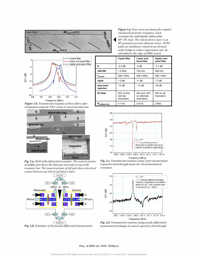
RFIN +DC2
RFOUT +DC315umFigure 1.a: Four series mechanically-coupled checkered-electrode resonators. Each resonator has individually addressable RF+DC lines. The silicon device layer is an RF ground to prevent substrate losses. All RF paths are metalized, routed on an elevated oxide bridge to reduce capacitance and de-embedded to the edge of DRIE trench.g f
4-pole filter Lower sub-band filter
Higher sub-band filter
IL -2.4 dB -2 dB -3.1 dB
3dB BW 1.4 MHz 720 kHz 660 kHz
fCENTER 508.7 MHz 508.3 MHz. 509.1 MHz
ripple < 2 dB <1 dB < 3 dB
stop band rejection
-14 dB - 14 dB -20 dB
DC Bias 50V on first and last resonators
40V and -40V on alternate resonators.
40V on all resonators
RTERMINATION 4.1 k 2.8 k 2.9kFigure 1.b: Transmission response of three filters after termination using the PNA’s pole-Z conversion function.
G Gelectrode vias
S
ground via
S
G
electrode vias
Aluminumepi-si cap
Fig. 2.a: SEM of the fabricated resonator. The zoom-in picture of middle part shows the thin poly electrode on top of the resonator bar. The zoom-in picture of left part shows electrical contact between epi-silicon and device layer
signal pathresonator
16umFig. 2.c: Transmission response using 2-port measurement. Capacitive feed-through masks the electromechanical resonance.
contact between epi-silicon and device layer.
G G
GResonator Dummy
Drive Port
0° 180°
GNDVDC BiasT BiasT
RFout RFout
-RFin+RFin
Fig. 2.d: Transmission response using pseudo-differential measurement technique to cancel capacitive feed-through.
G G
Sense Port
0° 0°
BiasT BiasT GNDVDC
Fig. 2.b: Schematic of the pseudo-differential measurement.
Proc. of SPIE Vol. 7679 76790J-4
Downloaded from SPIE Digital Library on 11 Mar 2012 to 132.236.27.111. Terms of Use: http://spiedl.org/terms

'rrrrrr'-30 :±H++H+±+irrr.TTiTTr
-50 1
I I IFf-±-Ff--
-00 4-4-
-25
1-I-5OOIvnPe,tT....à
ii- t1-i-.40
-15 4 i-4ii PutTerrru.-20 4
125 I F-+$0
-36
-40
Fig. 3.a: SEM of a monolithically integrated single pole dual throw PZT MEMS switch and two PZT contour mode filters.
Fig. 3.b: SEM and S21 data at 0 volts (OFF) and 7 volts (ON) for the PZT RF MEMS switch.
Fig. 3.c: (a) S21 response for an integrated SP2T switch and filter with the switch in the off-state (0 V), (b) S21 response for the left switch and filter with the switch on (7 V) and with 10 VDC applied to the filter, and (c) S21 response for the right switch and filter with the switch on (7 V) and with 10 VDC applied to the filter.
Water drop rolling over resonator
(a) Tuning Range: 0.1%(a)
Water left behind in gapAnchor failure. Onset of pull-in
( )
-40
ansm
issi
on (d
B)
-35
45
-30
-40
ansm
issi
on (d
B)
-35
45
-30(b) RX = 3.9kQ = 3800VP = 5V
Tuning Range: 3%
Onset of Electrolysis
(b)
Figure 4.a. (a) Schematic of water droplet rolled across the resonator, wicking the transducer gap, but minimizing the water left underneath the resonator (b) transmission response: Q of 3,800 at 42 MHz with Rx = 3.9 k
Figure 4.b. (a) 0.1% resonant frequency tuning of the air-gap transduced disk resonator before anchor failure, (b) In DI water, the resonator is tuned up to 3%, before the onset of electrolysis.
Frequency (MHz)
Tra -45
-5041.9 42.0 42.1 42.2 42.3
Frequency (MHz)
Tra -45
-5041.9 42.0 42.1 42.2 42.3
Onset of Electrolysis
Proc. of SPIE Vol. 7679 76790J-5
Downloaded from SPIE Digital Library on 11 Mar 2012 to 132.236.27.111. Terms of Use: http://spiedl.org/terms

1\1\1\I\/IvvvvFig.5.a. left: SEM of
LO signal generator
DC supplyParametric Network Analyzer
DUTBias-T
RF input
LO + DC
RF - LO
LO signal generator
DC supplyParametric Network Analyzer
DUTBias-T
RF input
LO + DC
RF - LO
dg
VDCvin iout
-L/2 L/2x = 0
u3(x)
( )
dg
VDCvin iout
-L/2 L/2x = 0
u3(x)
( )
polysilicon electrode
15 nm nitride
polysilicon inner body
polysilicon electrode
15 nm nitride
polysilicon inner body
Fig.5.a. left: SEM of 6.2 GHz polysiliconbar resonator (4.3 x 40 x 2 m). top: SEM of resonator cross section, showing 15nm solid nitride film.
Fig.5.b. Scalar mixer measurement of the 3-port MEMS resonator. The resonator (DUT) acts as a mixer for the input RF and LO signals. The resonance is detected at RF – LO.
u9(x)u9(x)
Fig.5.c. Cross section of resonator showing dielectric (yellow), with normalized mode shapes of 3rd and 9th harmonics of longitudinal resonance (1D in-plane motion).
no signalno signal
|2d/L|Fig.5.d. Motional impedance vs. position of dielectric transducer in 3rd and 9th harmonics of 8 different resonators. Selective positioning of dielectric can excite only 9th harmonic at 4.72 GHz, only 3rd harmonic at 1.55 GHz, and both 3rd and 9th harmonics.
VD > VG-VT
VG
VS = GND
inversion
excitation force
IDVD = 4.5 VVG = 5 VV CC = -0 5 V
fres = 11.72 GHz
f3dB = 6 4 MHz
Vacc > VD - VGaccumulation
force VACC = -0.5 VPin = -20 dBm
f3dB 6.4 MHzQ = 1831fres·Q = 2.1·1013
200 nm
Fig.6. Schematic, SEM and electrical transfer characteristics of an 11.7GHz Resonant Body Transistor.
Proc. of SPIE Vol. 7679 76790J-6
Downloaded from SPIE Digital Library on 11 Mar 2012 to 132.236.27.111. Terms of Use: http://spiedl.org/terms


![› oxidemems › papers › Umesh_AE.pdf Silicon acoustoelectronics with thin film lithium …bus for manipulation of spin qubits [21]. Recently, complen tary metal oxide semiconductor](https://static.fdocuments.us/doc/165x107/5e5c09584200727847628e9d/a-oxidemems-a-papers-a-umeshaepdf-silicon-acoustoelectronics-with-thin-film.jpg)