
MiCOM P40L - Grid Automationgridautomation.pl/dane/Dokumentacja PDF/1... · 3.6 Main Processor SNMP...
50
MiCOM P40L © - ALSTOM GRID. All rights reserved. Information contained in this document is indicative only. No representation or warranty is given or should be relied on that it is complete or correct or will apply to any particular project. This will depend on the technical and commercial circumstances. It is provided without liability and is subject to change without notice. Reproduction, use or disclosure to third parties, without express written authority, is strictly prohibited. Addendum Product Range: P40L Platform Hardware Version: M Platform Software Versions: 80, 81, 82, 83 Publication Reference: P40L-AD-ED2-EN-1
Transcript of MiCOM P40L - Grid Automationgridautomation.pl/dane/Dokumentacja PDF/1... · 3.6 Main Processor SNMP...
MiCOM P40L
© - ALSTOM GRID. All rights reserved. Information contained in this document is indicative only. No representation or warranty is given or should be relied on that it
is complete or correct or will apply to any particular project. This will depend on the technical and commercial circumstances. It is provided without liability and is
subject to change without notice. Reproduction, use or disclosure to third parties, without express written authority, is strictly prohibited.
Addendum Product Range: P40L
Platform Hardware Version: M
Platform Software Versions: 80, 81, 82, 83
Publication Reference: P40L-AD-ED2-EN-1

P40L
2 P40L-AD-ED2-EN-1

P40L
P40L-AD-ED2-EN-1 3
TABLE OF CONTENTS
1 INTRODUCTION 5 1.1 Scope of this Addendum 7 1.2 New ordering Information 7 1.2.1 P443 8 1.2.2 P446 10 1.2.3 P543 12 1.2.4 P544 14 1.2.5 P545 16 1.2.6 P546 18 1.2.7 P841 20
2 IEC 61850 EDITION 2 21 2.1 Backward Compatibility 21 2.2 Edition 2 Common Data Classes 22 2.3 Standby Protection Function Redundancy 23
3 SIMPLE NETWORK MANAGEMENT PROTOCOL 26 3.1 Introduction 26 3.2 SNMP Management Information Bases (MIBs) 26 3.3 Main Processor MIB Structure 26 3.4 Redundant Ethernet Board MIB Structure 27 3.5 Accessing the MIB 29 3.6 Main Processor SNMP Configuration 29
4 IEEE 1588 PRECISION TIME PROTOCOL 31 4.1 Accuracy and Delay Calculation 31 4.2 PTP Domains 32
5 NEW TESTING FUNCTIONALITY 33 5.1 Using IEC 61850 Edition 2 Test Modes 33 5.1.1 IED Test Mode Behaviour 33 5.1.2 Sampled Value Test Mode Behaviour 34
5.2 Simulated input behaviour 34 5.3 Testing examples using IEC 61850 Ed2 35 5.3.1 Procedure for testing with real values without operating plant 35 5.3.2 Procedure for Testing with Simulated Values without Operating Plant 36 5.3.3 Procedure for Testing with Simulated Values to Operate Plant 37 5.3.4 Contact Test 38
6 DATE AND TIME CONFIGURATION 39 6.1 Using an SNTP signal 39 6.2 Using an IRIG-B Signal 39 6.3 Using an IEEE 1588 PTP Signal 39 6.4 Without a Timing Source Signal 40

P40L
4 P40L-AD-ED2-EN-1
7 NEW TECHNICAL SPECIFICATIONS 41
8 SETTINGS AND RECORDS 42 8.1 Removed Settings 45 8.2 Renamed Settings 45
9 DDB SIGNALS 46
10 WIRING DIAGRAMS 47

P40L
P40L-AD-ED2-EN-1 5
1 INTRODUCTION
Major new functionality is now available for the P540D range of transmission protection products. This is focussed on digital substation applications and includes IEC 61850 Edition 2 compliance, comprehensive test mode and simulation capability, editable IEC 61850 Logical Device and Logical Node naming, PTP (IEEE 1588) time synchronisation, and SNMP.
This addendum describes these functional enhancements, which have occurred to selected products from the P540D range since the release of the last full technical manuals and subsequent addendums.
There are three streams of released software for the P540D product range, as depicted by the following diagram.

P40L
6 P40L-AD-ED2-EN-1
V00062
XCPU3Cyber-securityNew Protection functions
P445: P41P54x No Distance: M61
P841A: M61All other products: M71
New Protection functions
P445: P45P54x No Distance: M65
P841A: M65All other products: M75
Current Differential Starters for P54xOther improvements
P445: P46P54x No Distance: M66
P841A: M66All other products: M76
P446, P546, P841B: M74
Sub-cycle differential for non-distance versions
P543, P545: M63
IEC 61850 Edition 2IEEE 1588 support
P543, P545: M83
IEC 61850 Edition 2IEEE 1588 support40TE case
P446, P546, P841B: M80
XCPU3Cyber-securityNCIT (9-2LE interface)
NCIT (now obsolete)
Non-distance products: M81Distance products: M82
IEC 61850 Edition 2IEEE 1588 support
P445: J37P54x No Distance: K47
P841A: K47All other products: K57
P446, P546, P841B: M72
Conventional Stream NCIT Stream
Sub-cycle Diff Stream
Figure 1: Version tree
The latest full technical manuals covering these products are as follows:
P40L
P40L-AD-ED2-EN-1 7
P443/EN/TM/E - Software version 71
P446/EN/TM/E - Software version 71
P543&5/EN/TM/M - Software version 71 (distance) and version 61 (no distance)
P544&6/EN/TM/M - Software version 71 (distance) and version 61 (no distance)
P445/EN/TM/D - Software version 41
P547/EN/TM/C - Software version 71
P841/EN/TM/C - Software version 61 (single-CB) and version 71 (dual-CB)
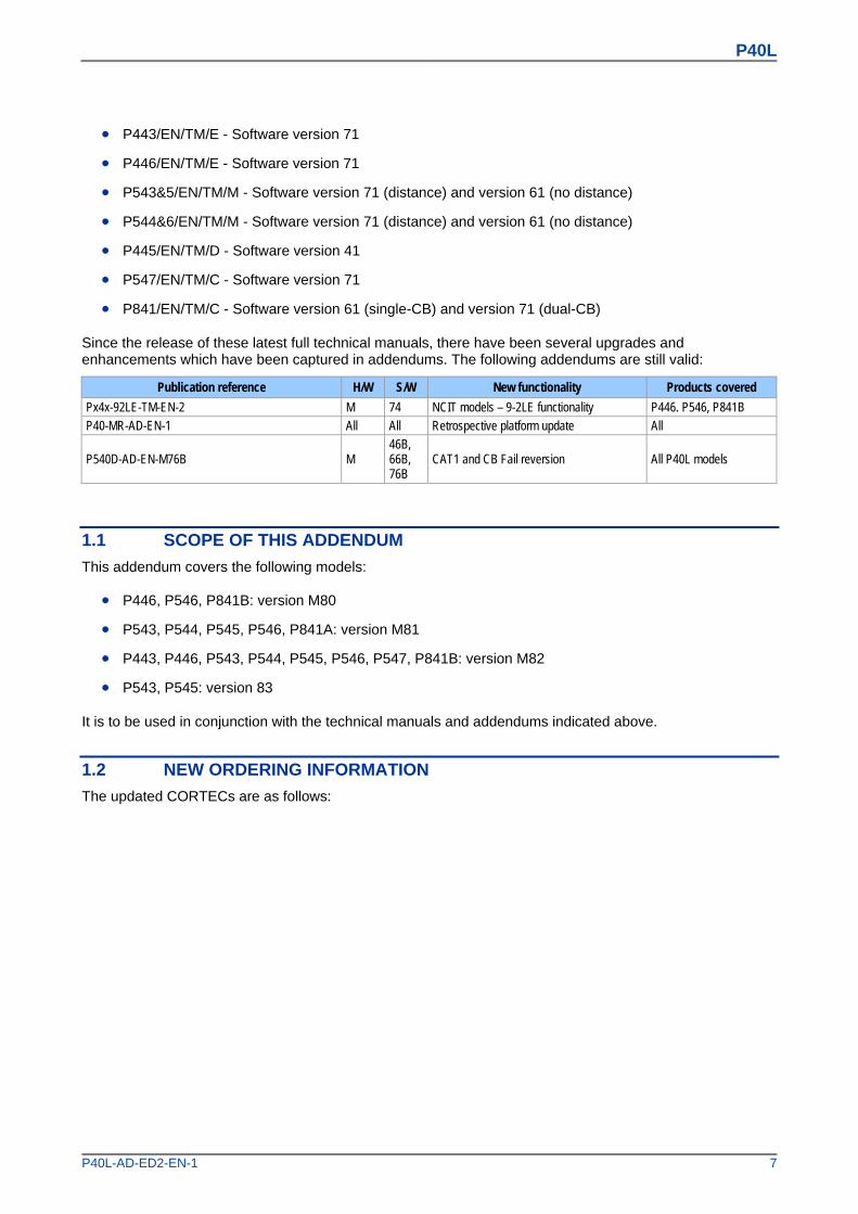
Since the release of these latest full technical manuals, there have been several upgrades and enhancements which have been captured in addendums. The following addendums are still valid:
Publication reference H/W S/W New functionality Products covered
Px4x-92LE-TM-EN-2 M 74 NCIT models – 9-2LE functionality P446. P546, P841B P40-MR-AD-EN-1 All All Retrospective platform update All
P540D-AD-EN-M76B M 46B, 66B, 76B
CAT1 and CB Fail reversion All P40L models
1.1 SCOPE OF THIS ADDENDUM
This addendum covers the following models:
P446, P546, P841B: version M80
P543, P544, P545, P546, P841A: version M81
P443, P446, P543, P544, P545, P546, P547, P841B: version M82
P543, P545: version 83
It is to be used in conjunction with the technical manuals and addendums indicated above.
1.2 NEW ORDERING INFORMATION
The updated CORTECs are as follows:

P40L
8 P40L-AD-ED2-EN-1
1.2.1 P443
V00044-1
Distance Protection P443 P443 **1 & 3 Pole tripping/reclosing MHO/Quad Distance with product options
Nominal auxiliary voltage24 - 54Vdc 748 - 125Vdc (40 - 100Vac) 8110 - 250 Vdc (100 - 240 Vac) 9
In/Vn rating Dual rated CT (1 & 5A : 100 - 120V) 1
Hardware options
Protocol Compatibilty
Standard - None 1, 3 & 4 1IRIG-B Only (Modulated) 1, 3 & 4 2Fibre Optic Converter Only 1, 3 & 4 3IRIG-B (Modulated) & Fibre Optic Converter 1, 3 & 4 4Ethernet (100Mbit/s) 6, 7 & 8 6Ethernet (100Mbit/s) plus IRIG-B (Modulated) * 6, 7 & 8 AEthernet (100Mbit/s) plus IRIG-B (Un-modulated) * 6, 7 & 8 BIRIG-B (Un-modulated) * 1, 3 & 4 CInterMiCOM + Courier Rear Port *** 1, 3 & 4 EInterMiCOM + Courier Rear Port + IRIG-B modulated *** 1, 3 & 4 FRedundant Ethernet Self-Healing Ring, 2 multi-mode fibre ports + Modulated IRIG-B ** 6, 7 & 8 GRedundant Ethernet Self-Healing Ring, 2 multi-mode fibre ports + Un-modulated IRIG-B ** 6, 7 & 8 HRedundant Ethernet RSTP, 2 multi-mode fibre ports + Modulated IRIG-B ** 6, 7 & 8 JRedundant Ethernet RSTP, 2 multi-mode fibre ports + Un-modulated IRIG-B ** 6, 7 & 8 KRedundant Ethernet Dual-Homing Star, 2 multi-mode fibre ports + Modulated IRIG-B ** 6, 7 & 8 LRedundant Ethernet Dual-Homing Star, 2 multi-mode fibre ports + Un-modulated IRIG-B ** 6, 7 & 8 MRedundant Ethernet PRP, 2 multi-mode fibre ports + Modulated IRIG-B **** 6, 7 & 8 NRedundant Ethernet PRP, 2 multi-mode fibre ports + Un-modulated IRIG-B **** 6, 7 & 8 P
* Only On K/M Suffix & later Relays)
** Only on Suffix K/M relays with 55 Software & later
*** Only on Suffix K/M relays with 57 Software & later, replaces hardware options '7' & '8'
**** Only on Suffix K relays with 55 Software & later
Product Options16 inputs and 24-standard outputs A24 inputs and 32-standard outputs B16 inputs and 16-standard plus 4-high break outputs C24 inputs and 16-standard plus 8-high break outputs D16 inputs and 24-standard outputs + 850nm dual channel E24 inputs and 32-standard outputs + 850nm dual channel F16 inputs and 16-standard plus 4-high break outputs + 850nm dual channel G24 inputs and 16-standard plus 8-high break outputs + 850nm dual channel H16 inputs and 24-standard outputs + 1300nm SM single channel I24 inputs and 32-standard outputs + 1300nm SM single channel J16 inputs and 16-standard plus 4-high break outputs + 1300nm SM single channel K24 inputs and 16-standard plus 8-high break outputs + 1300nm SM single channel L16 inputs and 24-standard outputs + 1300nm SM dual channel M24 inputs and 32-standard outputs + 1300nm SM dual channel N16 inputs and 16-standard plus 4-high break outputs + 1300nm SM dual channel O24 inputs and 16-standard plus 8-high break outputs + 1300nm SM dual channel P16 inputs and 24-standard outputs + 1300nm MM single channel Q24 inputs and 32-standard outputs + 1300nm MM single channel R16 inputs and 16-standard plus 4-high break outputs + 1300nm MM single channel S24 inputs and 16-standard plus 8-high break outputs + 1300nm MM single channel T16 inputs and 24-standard outputs + 1300nm MM dual channel U24 inputs and 32-standard outputs + 1300nm MM dual channel V16 inputs and 16-standard plus 4-high break outputs + 1300nm MM dual channel W24 inputs and 16-standard plus 8-high break outputs + 1300nm MM dual channel X32 inputs and 32-standard outputs (Only available on Design Suffix K/M devices with version "54" software and later) Y24 inputs and 32-standard outputs + 850nm MM + 1300nm SM dual channel Z24 inputs and 16-standard plus 8-high break outputs + 850nm MM + 1300nm SM dual channel 124 inputs and 32-standard outputs + 1300nm SM + 850nm MM dual channel 224 inputs and 16-standard plus 8-high break outputs + 1300nm SM + 850nm MM dual channel 324 inputs and 32-standard outputs + 850nm MM + 1300nm MM dual channel 424 inputs and 16-standard plus 8-high break outputs + 850nm MM + 1300nm MM dual channel 524 inputs and 32-standard outputs + 1300nm MM + 850nm MM dual channel 624 inputs and 16-standard plus 8-high break outputs + 1300nm MM + 850nm MM dual channel 7
Figure 2: P443 Cortec – part 1

P40L
P40L-AD-ED2-EN-1 9
V00044-2
Distance Protection P443 P443 ** 0Protocol optionsK-Bus 1IEC60870-5-103 3DNP3.0 4IEC61850 + Courier via rear RS485 port 6IEC61850+IEC60870-5-103 via rear RS485 port 7DNP3.0 Over Ethernet * 8* Available on Design Suffix K/M devices with version "54" software and laterMountingFlush/Panel Mounting with Harsh Environment Coating M19" Rack Mounting with Harsh Environmental Coating N
LanguageEnglish, French, German, Spanish 0English, French, German, Russian (Only available on Design Suffix K/M and later devices) 5English, Italian, Polish and Portuguese (Software '75' and later) 7Chinese, English or French via HMI, with English or French only via Communications port (With Suffix K/M & '52' and later software) C
Software versionDate and application dependant **
Customer specific optionsStandard version 0Customer version A
Hardware versionEnhanced Main Processor (CPU2) with hotkeys, dual characteristic optos JExtended main processor (XCPU2) With Function Keys & Tri-colour LEDs KAs K plus increased main processor memory (XCPU3), Cyber Security M
Hardware Compatibilty1, 2, 3, 4, C, E & F
6, A, B, G, H, J, K, L, M, N, P
1, 2, 3, 4, C, E & F1, 2, 3, 4, C, E & F
6, A, B, G, H, J, K, L, M, N, P6, A, B, G, H, J, K, L, M, N, P
Figure 3: P443 Cortec – part 2
P40L
10 P40L-AD-ED2-EN-1
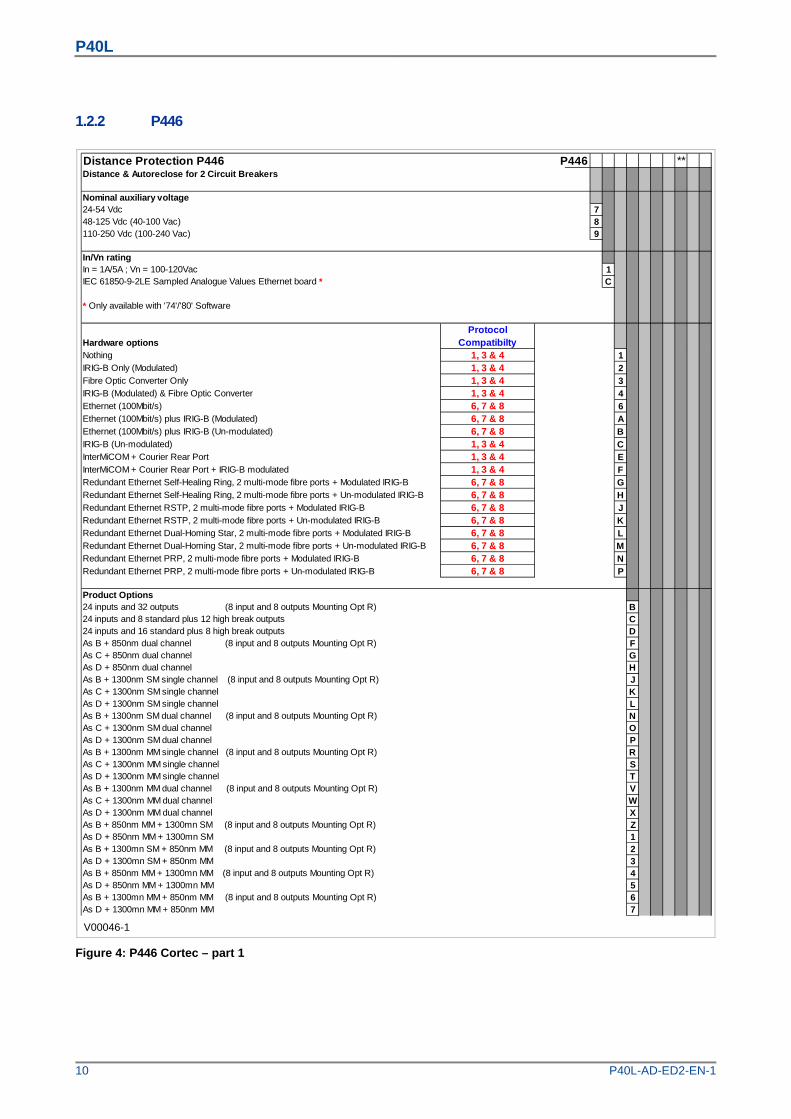
1.2.2 P446
V00046-1
Distance Protection P446 P446 **Distance & Autoreclose for 2 Circuit Breakers
Nominal auxiliary voltage24-54 Vdc 748-125 Vdc (40-100 Vac) 8110-250 Vdc (100-240 Vac) 9
In/Vn rating In = 1A/5A ; Vn = 100-120Vac 1IEC 61850-9-2LE Sampled Analogue Values Ethernet board * C
* Only available with '74'/'80' Software
Hardware options
Protocol Compatibilty
Nothing 1, 3 & 4 1IRIG-B Only (Modulated) 1, 3 & 4 2Fibre Optic Converter Only 1, 3 & 4 3IRIG-B (Modulated) & Fibre Optic Converter 1, 3 & 4 4Ethernet (100Mbit/s) 6, 7 & 8 6Ethernet (100Mbit/s) plus IRIG-B (Modulated) 6, 7 & 8 AEthernet (100Mbit/s) plus IRIG-B (Un-modulated) 6, 7 & 8 BIRIG-B (Un-modulated) 1, 3 & 4 CInterMiCOM + Courier Rear Port 1, 3 & 4 EInterMiCOM + Courier Rear Port + IRIG-B modulated 1, 3 & 4 FRedundant Ethernet Self-Healing Ring, 2 multi-mode fibre ports + Modulated IRIG-B 6, 7 & 8 GRedundant Ethernet Self-Healing Ring, 2 multi-mode fibre ports + Un-modulated IRIG-B 6, 7 & 8 HRedundant Ethernet RSTP, 2 multi-mode fibre ports + Modulated IRIG-B 6, 7 & 8 JRedundant Ethernet RSTP, 2 multi-mode fibre ports + Un-modulated IRIG-B 6, 7 & 8 KRedundant Ethernet Dual-Homing Star, 2 multi-mode fibre ports + Modulated IRIG-B 6, 7 & 8 LRedundant Ethernet Dual-Homing Star, 2 multi-mode fibre ports + Un-modulated IRIG-B 6, 7 & 8 MRedundant Ethernet PRP, 2 multi-mode fibre ports + Modulated IRIG-B 6, 7 & 8 NRedundant Ethernet PRP, 2 multi-mode fibre ports + Un-modulated IRIG-B 6, 7 & 8 P
Product Options24 inputs and 32 outputs (8 input and 8 outputs Mounting Opt R) B24 inputs and 8 standard plus 12 high break outputs C24 inputs and 16 standard plus 8 high break outputs DAs B + 850nm dual channel (8 input and 8 outputs Mounting Opt R) FAs C + 850nm dual channel GAs D + 850nm dual channel HAs B + 1300nm SM single channel (8 input and 8 outputs Mounting Opt R) JAs C + 1300nm SM single channel KAs D + 1300nm SM single channel LAs B + 1300nm SM dual channel (8 input and 8 outputs Mounting Opt R) NAs C + 1300nm SM dual channel OAs D + 1300nm SM dual channel PAs B + 1300nm MM single channel (8 input and 8 outputs Mounting Opt R) RAs C + 1300nm MM single channel SAs D + 1300nm MM single channel TAs B + 1300nm MM dual channel (8 input and 8 outputs Mounting Opt R) VAs C + 1300nm MM dual channel WAs D + 1300nm MM dual channel XAs B + 850nm MM + 1300mn SM (8 input and 8 outputs Mounting Opt R) ZAs D + 850nm MM + 1300mn SM 1As B + 1300mn SM + 850nm MM (8 input and 8 outputs Mounting Opt R) 2As D + 1300mn SM + 850nm MM 3As B + 850nm MM + 1300mn MM (8 input and 8 outputs Mounting Opt R) 4As D + 850nm MM + 1300mn MM 5As B + 1300mn MM + 850nm MM (8 input and 8 outputs Mounting Opt R) 6As D + 1300mn MM + 850nm MM 7
Figure 4: P446 Cortec – part 1
P40L
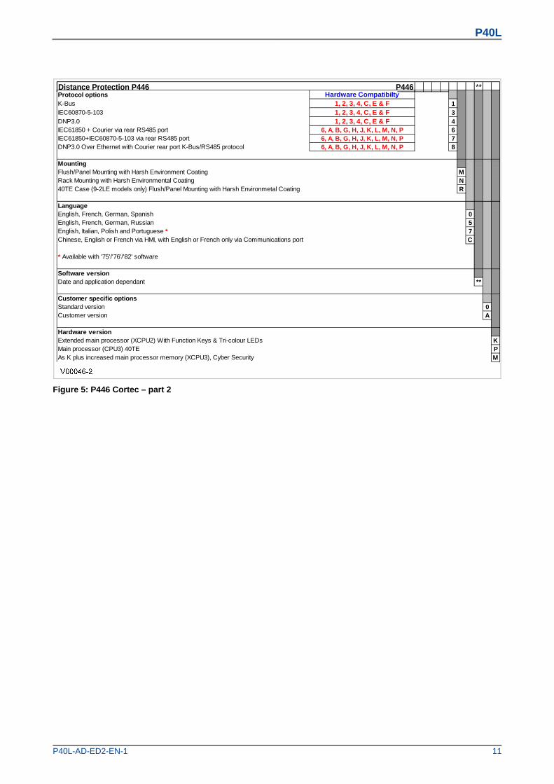
P40L-AD-ED2-EN-1 11
Distance Protection P446 P446 **Protocol optionsK-Bus 1IEC60870-5-103 3DNP3.0 4IEC61850 + Courier via rear RS485 port 6IEC61850+IEC60870-5-103 via rear RS485 port 7DNP3.0 Over Ethernet with Courier rear port K-Bus/RS485 protocol 8
MountingFlush/Panel Mounting with Harsh Environment Coating MRack Mounting with Harsh Environmental Coating N40TE Case (9-2LE models only) Flush/Panel Mounting with Harsh Environmetal Coating R
LanguageEnglish, French, German, Spanish 0English, French, German, Russian 5English, Italian, Polish and Portuguese * 7Chinese, English or French via HMI, with English or French only via Communications port C
* Available with '75'/'76'/'82' software
Software versionDate and application dependant **
Customer specific optionsStandard version 0Customer version A
Hardware versionExtended main processor (XCPU2) With Function Keys & Tri-colour LEDs KMain processor (CPU3) 40TE PAs K plus increased main processor memory (XCPU3), Cyber Security M
6, A, B, G, H, J, K, L, M, N, P6, A, B, G, H, J, K, L, M, N, P
6, A, B, G, H, J, K, L, M, N, P
Hardware Compatibilty1, 2, 3, 4, C, E & F1, 2, 3, 4, C, E & F1, 2, 3, 4, C, E & F
Figure 5: P446 Cortec – part 2

P40L
12 P40L-AD-ED2-EN-1
1.2.3 P543
Current differential - With distance backup, 1/3 pole autoreclose and check synchronising P543 **Nominal auxiliary voltage24-54 Vdc 748-125 Vdc (40-100 Vac) 8110-250 Vdc (100-240 Vac) 9
In/Vn ratingIn = 1A/5A ; Vn = 100-120Vac 1
Hardware optionsProtocol
CompatibiltyStandard - None 1, 2, 3 & 4 1IRIG-B Only (Modulated) 1, 2, 3 & 4 2Fibre Optic Converter Only 1, 2, 3 & 4 3IRIG-B (Modulated) & Fibre Optic Converter 1, 2, 3 & 4 4Ethernet (10Mbit/s) * 5 5Ethernet (100Mbit/s) 5, 6, 7 & 8 6Ethernet (100Mbit/s) plus IRIG-B (Modulated) ** 6, 7 & 8 AEthernet (100Mbit/s) plus IRIG-B (Un-modulated) ** 6, 7 & 8 BIRIG-B (Un-modulated) ** 1, 2, 3 & 4 CInterMiCOM + Courier Rear Port **** 1, 2, 3 & 4 EInterMiCOM + Courier Rear Port + IRIG-B modulated **** 1, 2, 3 & 4 FRedundant Ethernet Self-Healing Ring, 2 multi-mode fibre ports + Modulated IRIG-B *** 6, 7 & 8 GRedundant Ethernet Self-Healing Ring, 2 multi-mode fibre ports + Un-modulated IRIG-B *** 6, 7 & 8 HRedundant Ethernet RSTP, 2 multi-mode fibre ports + Modulated IRIG-B *** 6, 7 & 8 JRedundant Ethernet RSTP, 2 multi-mode fibre ports + Un-modulated IRIG-B *** 6, 7 & 8 KRedundant Ethernet Dual-Homing Star, 2 multi-mode fibre ports + Modulated IRIG-B *** 6, 7 & 8 LRedundant Ethernet Dual-Homing Star, 2 multi-mode fibre ports + Un-modulated IRIG-B *** 6, 7 & 8 MRedundant Ethernet PRP, 2 multi-mode fibre ports + Modulated IRIG-B *** 6, 7 & 8 NRedundant Ethernet PRP, 2 multi-mode fibre ports + Un-modulated IRIG-B *** 6, 7 & 8 P
* Only on Suffix G or J Relays** Only on Suffix K or M relays*** Only on Suffix K or M relays with 45/55 Software and later**** Only on Suffix K or M relays with 47/57 Software, replaces hardware options '7' & '8'
Product OptionsCh1=850nm multi-mode, Ch2=850nm multi-mode ACh1=1300nm single-mode, Ch2=not fitted (2 Terminal only) BCh1=1300nm single-mode, Ch2=1300nm single-mode CCh1=1300nm multi-mode, Ch2=not fitted (2 Terminal only) DCh1=1300nm multi-mode, Ch2=1300nm multi-mode ECh1=1550nm single-mode, Ch2=not fitted (2 Terminal only) FCh1=1550nm single-mode, Ch2=1550nm single-mode GCh1=850nm multi-mode, Ch2=1300nm single-mode * HCh1=850nm multi-mode, Ch2=1300nm multi-mode * JCh1=850nm multi-mode, Ch2=1550nm single-mode * KCh1=1300nm single-mode, Ch2=850nm multi-mode * LCh1=1300nm multi-mode, Ch2=850nm multi-mode * MReserved for future single channel NReserved for future single channel PCh1 1550nm single-mode, Ch2 850nm multi-mode * RCh1=850nm multi-mode, Ch2=850nm multi-mode + High Break ** SCh1=1300nm single-mode, Ch2=not fitted (2 Terminal only) + High Break ** TCh1=1300nm single-mode , Ch2=1300nm single-mode + High Break ** UCh1=1300nm multi-mode, Ch2=not fitted (2 Terminal only) + High Break ** VCh1=1300nm multi-mode, Ch2=1300nm multi-mode + High Break ** WCh1=1550nm single-mode, Ch2=not fitted (2 Terminal only) + High Break ** XReserved - was used for RWE special YCh1=1550nm single-mode, Ch2=1550nm single-mode + High Break ** ZCh1=850nm multi-mode, Ch2=1300nm single-mode + High Break ** 0Ch1=850nm multi-mode, Ch2=1300nm multi-mode + High Break ** 1Ch1=850nm multi-mode, Ch2=1550nm single-mode + High Break ** 2Ch1=1300nm single-mode, Ch2=850nm multi-mode + High Break ** 3Ch1=1300nm multi-mode, Ch2=850nm multi-mode + High Break ** 4Ch1 1550nm single-mode, Ch2 850nm multi-mode + High Break ** 5Reserved for future single channel 6Reserved for future single channel 7
* Design Suffix G, J, K & M only** Design Suffix K & M only
Figure 6: P543 Cortec – part 1
P40L
P40L-AD-ED2-EN-1 13
V00047-2
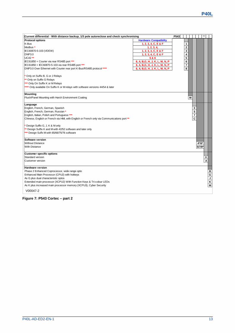
Current differential - With distance backup, 1/3 pole autoreclose and check synchronising P543 **
Protocol optionsK-Bus 1Modbus * 2IEC60870-5-103 (VDEW) 3DNP3.0 4UCA2 ** 5IEC61850 + Courier via rear RS485 port *** 6IEC61850 + IEC60870-5-103 via rear RS485 port *** 7DNP3.0 Over Ethernet with Courier rear port K-Bus/RS485 protocol **** 8
* Only on Suffix B, G or J Relays
** Only on Suffix G Relays
*** Only On Suffix K or M Relays
**** Only available On Suffix K or M relays with software versions 44/54 & later
MountingFlush/Panel Mounting with Harsh Environment Coating M
LanguageEnglish, French, German, Spanish 0English, French, German, Russian * 5English, Italian, Polish and Portuguese *** 7Chinese, English or French via HMI, with English or French only via Communications port ** C
* Design Suffix G, J, K & M only** Design Suffix K and M with 42/52 software and later only*** Design Suffx M with 65/66/75/76 software
Software versionWithout Distance 4*/6*With Distance 5/7/8*
Customer specific optionsStandard version 0Customer version A
Hardware versionPhase 2 Enhanced Coprocessor, wide range opto BEnhanced Main Processor (CPU2) with hotkeys GAs G plus dual characteristic optos JExtended main processor (XCPU2) With Function Keys & Tri-colour LEDs KAs K plus increased main processor memory (XCPU3), Cyber Security M
Hardware Compatibilty1, 2, 3, 4, C, E & F
1, 2, 3, 4,1, 2, 3, 4, C, E & F
6, A, B,G, H, J, K, L, M, N, P
1, 2, 3, 4, C, E & F5 & 6
6, A, B,G, H, J, K, L, M, N, P6, A, B,G, H, J, K, L, M, N, P
Figure 7: P543 Cortec – part 2
P40L
14 P40L-AD-ED2-EN-1
1.2.4 P544
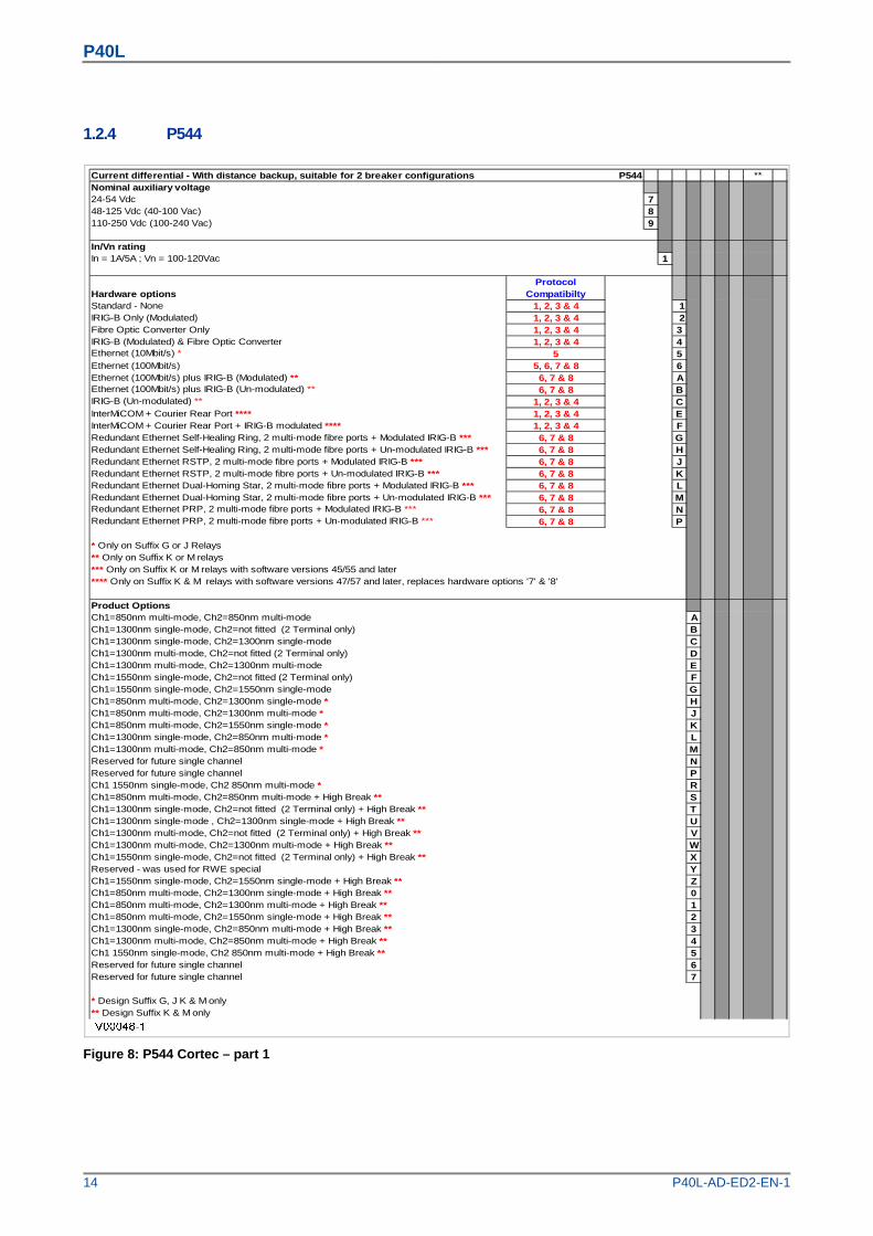
Current differential - With distance backup, suitable for 2 breaker configurations P544 **Nominal auxiliary voltage24-54 Vdc 748-125 Vdc (40-100 Vac) 8110-250 Vdc (100-240 Vac) 9
In/Vn ratingIn = 1A/5A ; Vn = 100-120Vac 1
Hardware optionsProtocol
CompatibiltyStandard - None 1, 2, 3 & 4 1IRIG-B Only (Modulated) 1, 2, 3 & 4 2Fibre Optic Converter Only 1, 2, 3 & 4 3IRIG-B (Modulated) & Fibre Optic Converter 1, 2, 3 & 4 4Ethernet (10Mbit/s) * 5 5Ethernet (100Mbit/s) 5, 6, 7 & 8 6Ethernet (100Mbit/s) plus IRIG-B (Modulated) ** 6, 7 & 8 AEthernet (100Mbit/s) plus IRIG-B (Un-modulated) ** 6, 7 & 8 BIRIG-B (Un-modulated) ** 1, 2, 3 & 4 CInterMiCOM + Courier Rear Port **** 1, 2, 3 & 4 EInterMiCOM + Courier Rear Port + IRIG-B modulated **** 1, 2, 3 & 4 FRedundant Ethernet Self-Healing Ring, 2 multi-mode fibre ports + Modulated IRIG-B *** 6, 7 & 8 GRedundant Ethernet Self-Healing Ring, 2 multi-mode fibre ports + Un-modulated IRIG-B *** 6, 7 & 8 HRedundant Ethernet RSTP, 2 multi-mode fibre ports + Modulated IRIG-B *** 6, 7 & 8 JRedundant Ethernet RSTP, 2 multi-mode fibre ports + Un-modulated IRIG-B *** 6, 7 & 8 KRedundant Ethernet Dual-Homing Star, 2 multi-mode fibre ports + Modulated IRIG-B *** 6, 7 & 8 LRedundant Ethernet Dual-Homing Star, 2 multi-mode fibre ports + Un-modulated IRIG-B *** 6, 7 & 8 MRedundant Ethernet PRP, 2 multi-mode fibre ports + Modulated IRIG-B *** 6, 7 & 8 NRedundant Ethernet PRP, 2 multi-mode fibre ports + Un-modulated IRIG-B *** 6, 7 & 8 P
* Only on Suffix G or J Relays** Only on Suffix K or M relays*** Only on Suffix K or M relays with software versions 45/55 and later**** Only on Suffix K & M relays with software versions 47/57 and later, replaces hardware options '7' & '8'
Product OptionsCh1=850nm multi-mode, Ch2=850nm multi-mode ACh1=1300nm single-mode, Ch2=not fitted (2 Terminal only) BCh1=1300nm single-mode, Ch2=1300nm single-mode CCh1=1300nm multi-mode, Ch2=not fitted (2 Terminal only) DCh1=1300nm multi-mode, Ch2=1300nm multi-mode ECh1=1550nm single-mode, Ch2=not fitted (2 Terminal only) FCh1=1550nm single-mode, Ch2=1550nm single-mode GCh1=850nm multi-mode, Ch2=1300nm single-mode * HCh1=850nm multi-mode, Ch2=1300nm multi-mode * JCh1=850nm multi-mode, Ch2=1550nm single-mode * KCh1=1300nm single-mode, Ch2=850nm multi-mode * LCh1=1300nm multi-mode, Ch2=850nm multi-mode * MReserved for future single channel NReserved for future single channel PCh1 1550nm single-mode, Ch2 850nm multi-mode * RCh1=850nm multi-mode, Ch2=850nm multi-mode + High Break ** SCh1=1300nm single-mode, Ch2=not fitted (2 Terminal only) + High Break ** TCh1=1300nm single-mode , Ch2=1300nm single-mode + High Break ** UCh1=1300nm multi-mode, Ch2=not fitted (2 Terminal only) + High Break ** VCh1=1300nm multi-mode, Ch2=1300nm multi-mode + High Break ** WCh1=1550nm single-mode, Ch2=not fitted (2 Terminal only) + High Break ** XReserved - was used for RWE special YCh1=1550nm single-mode, Ch2=1550nm single-mode + High Break ** ZCh1=850nm multi-mode, Ch2=1300nm single-mode + High Break ** 0Ch1=850nm multi-mode, Ch2=1300nm multi-mode + High Break ** 1Ch1=850nm multi-mode, Ch2=1550nm single-mode + High Break ** 2Ch1=1300nm single-mode, Ch2=850nm multi-mode + High Break ** 3Ch1=1300nm multi-mode, Ch2=850nm multi-mode + High Break ** 4Ch1 1550nm single-mode, Ch2 850nm multi-mode + High Break ** 5Reserved for future single channel 6Reserved for future single channel 7
* Design Suffix G, J K & M only** Design Suffix K & M only
Figure 8: P544 Cortec – part 1
P40L
P40L-AD-ED2-EN-1 15
V00048-2
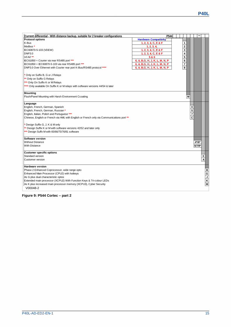
Current differential - With distance backup, suitable for 2 breaker configurations P544 **Protocol optionsK-Bus 1Modbus * 2IEC60870-5-103 (VDEW) 3DNP3.0 4UCA2 ** 5IEC61850 + Courier via rear RS485 port *** 6IEC61850 + IEC60870-5-103 via rear RS485 port *** 7DNP3.0 Over Ethernet with Courier rear port K-Bus/RS485 protocol **** 8
* Only on Suffix B, G or J Relays
** Only on Suffix G Relays
*** Only On Suffix K or M Relays
**** Only available On Suffix K or M relays with software versions 44/54 & later
MountingFlush/Panel Mounting with Harsh Environment Ccoating M
LanguageEnglish, French, German, Spanish 0English, French, German, Russian * 5English, Italian, Polish and Portuguese *** 7Chinese, English or French via HMI, with English or French only via Communications port ** C
* Design Suffix G, J, K & M only** Design Suffix K or M with software versions 42/52 and later only*** Design Suffx M with 65/66/75/76/81 software
Software versionWithout Distance 4*/6*With Distance 5/7/8*
Customer specific optionsStandard version 0Customer version A
Hardware versionPhase 2 Enhanced Coprocessor, wide range opto BEnhanced Main Processor (CPU2) with hotkeys GAs G plus dual characteristic optos JExtended main processor (XCPU2) With Function Keys & Tri-colour LEDs KAs K plus increased main processor memory (XCPU3), Cyber Security M
Hardware Compatibilty1, 2, 3, 4, C, E & F
1, 2, 3, 4,1, 2, 3, 4, C, E & F
6, A, B,G, H, J, K, L, M, N, P
1, 2, 3, 4, C, E & F5 & 6
6, A, B,G, H, J, K, L, M, N, P6, A, B,G, H, J, K, L, M, N, P
Figure 9: P544 Cortec – part 2

P40L
16 P40L-AD-ED2-EN-1
1.2.5 P545
Current differential - With distance backup, P545 **1/3 pole autoreclose and check synchronising, with 24 or 32 inputs, 32 outputs, GPS input.Nominal auxiliary voltage24-54 Vdc 748-125 Vdc (40-100 Vac) 8110-250 Vdc (100-240 Vac) 9
In/Vn ratingIn = 1A/5A ; Vn = 100-120Vac 1
Hardware optionsProtocol
CompatibiltyStandard - None 1, 2, 3 & 4 1IRIG-B Only (Modulated) 1, 2, 3 & 4 2Fibre Optic Converter Only 1, 2, 3 & 4 3IRIG-B (Modulated) & Fibre Optic Converter 1, 2, 3 & 4 4Ethernet (10Mbit/s) * 5 5Ethernet (100Mbit/s) 5, 6, 7 & 8 6Ethernet (100Mbit/s) plus IRIG-B (Modulated) ** 6, 7 & 8 AEthernet (100Mbit/s) plus IRIG-B (Un-modulated) ** 6, 7 & 8 BIRIG-B (Un-modulated) ** 1, 2, 3 & 4 CInterMiCOM + Courier Rear Port **** 1, 2, 3 & 4 EInterMiCOM + Courier Rear Port + IRIG-B modulated **** 1, 2, 3 & 4 FRedundant Ethernet Self-Healing Ring, 2 multi-mode fibre ports + Modulated IRIG-B *** 6, 7 & 8 GRedundant Ethernet Self-Healing Ring, 2 multi-mode fibre ports + Un-modulated IRIG-B *** 6, 7 & 8 HRedundant Ethernet RSTP, 2 multi-mode fibre ports + Modulated IRIG-B *** 6, 7 & 8 JRedundant Ethernet RSTP, 2 multi-mode fibre ports + Un-modulated IRIG-B *** 6, 7 & 8 KRedundant Ethernet Dual-Homing Star, 2 multi-mode fibre ports + Modulated IRIG-B *** 6, 7 & 8 LRedundant Ethernet Dual-Homing Star, 2 multi-mode fibre ports + Un-modulated IRIG-B *** 6, 7 & 8 MRedundant Ethernet PRP, 2 multi-mode fibre ports + Modulated IRIG-B *** 6, 7 & 8 NRedundant Ethernet PRP, 2 multi-mode fibre ports + Un-modulated IRIG-B *** 6, 7 & 8 P
* Only on Suffix G or J Relays** Only on Suffix K or M relays*** Only on Suffix K or M relays with software versions 45/55 and later**** Only on Suffix K or M relays with 47/57 Software, replaces hardware options '7' & '8'
Product Options: Basic Configuration of Ch1=850nm multi-mode, Ch2=850nm multi-mode ACh1=1300nm single-mode, Ch2=not fitted (2 Terminal only) BCh1=1300nm single-mode, Ch2=1300nm single-mode CCh1=1300nm multi-mode, Ch2=not fitted (2 Terminal only) DCh1=1300nm multi-mode, Ch2=1300nm multi-mode ECh1=1550nm single-mode, Ch2=not fitted (2 Terminal only) FCh1=1550nm single-mode, Ch2=1550nm single-mode GCh1=850nm multi-mode, Ch2=1300nm single-mode * HCh1=850nm multi-mode, Ch2=850nm multi-mode + 32 Inputs *** ICh1=850nm multi-mode, Ch2=1300nm multi-mode * JCh1=850nm multi-mode, Ch2=1550nm single-mode * KCh1=1300nm single-mode, Ch2=850nm multi-mode * LCh1=1300nm multi-mode, Ch2=850nm multi-mode * MCh1=1300nm single-mode, Ch2=not fitted (2 Terminal only) + 32 Inputs *** NCh1=1300nm single-mode, Ch2=1300nm single-mode + 32 Inputs *** OCh1=1300nm multi-mode, Ch2=not fitted (2 Terminal only) + 32 Inputs *** PCh1=1300nm multi-mode, Ch2=1300nm multi-mode + 32 Inputs *** QCh 1 1550nm single-mode, Ch 2 850nm multi-mode * RCh1=850nm multi-mode, Ch2=850nm multi-mode + High Break ** SCh1=1300nm single-mode, Ch2=not fitted (2 Terminal only) + High Break ** TCh1=1300nm single-mode, Ch2=1300nm single-mode + High Break ** UCh1=1300nm multi-mode, Ch2=not fitted (2 Terminal only) + High Break ** VCh1=1300nm multi-mode, Ch2=1300nm multi-mode + High Break ** WCh1=1550nm single-mode, Ch2=not fitted (2 Terminal only) + High Break ** XReserved - was used for RWE special YCh1=1550nm single-mode, Ch2=1550nm single-mode + High Break ** ZCh1=850nm multi-mode, Ch2=1300nm single-mode + High Break ** 0Ch1=850nm multi-mode, Ch2=1300nm multi-mode + High Break ** 1Ch1=850nm multi-mode, Ch2=1550nm single-mode + High Break ** 2Ch1=1300nm single-mode, Ch2=850nm multi-mode + High Break ** 3Ch1=1300nm multi-mode, Ch2=850nm multi-mode + High Break ** 4Ch 1 1550nm single-mode, Ch 2 850nm multi-mode + High Break ** 5Reserved for future single channel 6Reserved for future single channel 7Ch1=1550nm single-mode, Ch2=not fitted (2 Terminal only) + 32 Inputs *** 8Ch1=1550nm single-mode, Ch2=1550nm single-mode + 32 Inputs *** 9
* Design Suffix G, J, K or M only** Design Suffix K & M only*** Design Suffix K or M and software versions 44/54 and later
Figure 10: P545 Cortec – part 1
P40L
P40L-AD-ED2-EN-1 17
V00049-2
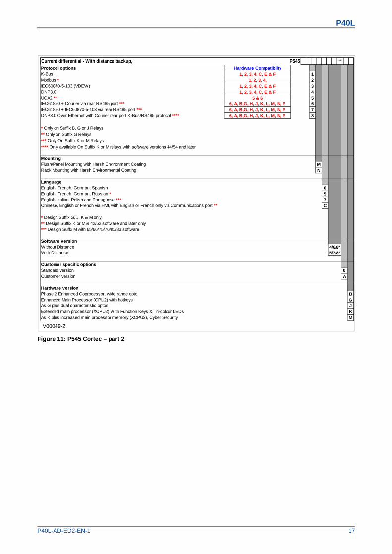
Current differential - With distance backup, P545 **Protocol optionsK-Bus 1Modbus * 2IEC60870-5-103 (VDEW) 3DNP3.0 4UCA2 ** 5IEC61850 + Courier via rear RS485 port *** 6IEC61850 + IEC60870-5-103 via rear RS485 port *** 7DNP3.0 Over Ethernet with Courier rear port K-Bus/RS485 protocol **** 8
* Only on Suffix B, G or J Relays
** Only on Suffix G Relays
*** Only On Suffix K or M Relays
**** Only available On Suffix K or M relays with software versions 44/54 and later
MountingFlush/Panel Mounting with Harsh Environment Coating MRack Mounting with Harsh Environmental Coating N
LanguageEnglish, French, German, Spanish 0English, French, German, Russian * 5English, Italian, Polish and Portuguese *** 7Chinese, English or French via HMI, with English or French only via Communications port ** C
* Design Suffix G, J, K & M only** Design Suffix K or M & 42/52 software and later only*** Design Suffx M with 65/66/75/76/81/83 software
Software versionWithout Distance 4/6/8*With Distance 5/7/8*
Customer specific optionsStandard version 0Customer version A
Hardware versionPhase 2 Enhanced Coprocessor, wide range opto BEnhanced Main Processor (CPU2) with hotkeys GAs G plus dual characteristic optos JExtended main processor (XCPU2) With Function Keys & Tri-colour LEDs KAs K plus increased main processor memory (XCPU3), Cyber Security M
Hardware Compatibilty1, 2, 3, 4, C, E & F
1, 2, 3, 4,1, 2, 3, 4, C, E & F
6, A, B,G, H, J, K, L, M, N, P
1, 2, 3, 4, C, E & F5 & 6
6, A, B,G, H, J, K, L, M, N, P6, A, B,G, H, J, K, L, M, N, P
Figure 11: P545 Cortec – part 2
P40L
18 P40L-AD-ED2-EN-1
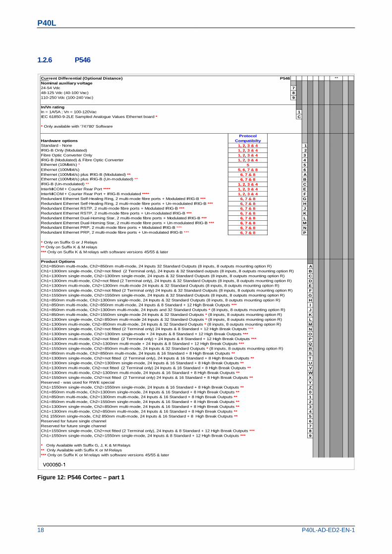
1.2.6 P546
Current Differential (Optional Distance) P546 **Nominal auxiliary voltage24-54 Vdc 748-125 Vdc (40-100 Vac) 8110-250 Vdc (100-240 Vac) 9
In/Vn ratingIn = 1A/5A ; Vn = 100-120Vac 1IEC 61850-9-2LE Sampled Analogue Values Ethernet board * C
* Only available with '74'/'80' Software
Hardware optionsProtocol
CompatibiltyStandard - None 1, 2, 3 & 4 1IRIG-B Only (Modulated) 1, 2, 3 & 4 2Fibre Optic Converter Only 1, 2, 3 & 4 3IRIG-B (Modulated) & Fibre Optic Converter 1, 2, 3 & 4 4Ethernet (10Mbit/s) * 5 5Ethernet (100Mbit/s) 5, 6, 7 & 8 6Ethernet (100Mbit/s) plus IRIG-B (Modulated) ** 6, 7 & 8 AEthernet (100Mbit/s) plus IRIG-B (Un-modulated) ** 6, 7 & 8 BIRIG-B (Un-modulated) ** 1, 2, 3 & 4 CInterMiCOM + Courier Rear Port **** 1, 2, 3 & 4 EInterMiCOM + Courier Rear Port + IRIG-B modulated **** 1, 2, 3 & 4 FRedundant Ethernet Self-Healing Ring, 2 multi-mode fibre ports + Modulated IRIG-B *** 6, 7 & 8 GRedundant Ethernet Self-Healing Ring, 2 multi-mode fibre ports + Un-modulated IRIG-B *** 6, 7 & 8 HRedundant Ethernet RSTP, 2 multi-mode fibre ports + Modulated IRIG-B *** 6, 7 & 8 JRedundant Ethernet RSTP, 2 multi-mode fibre ports + Un-modulated IRIG-B *** 6, 7 & 8 KRedundant Ethernet Dual-Homing Star, 2 multi-mode fibre ports + Modulated IRIG-B *** 6, 7 & 8 LRedundant Ethernet Dual-Homing Star, 2 multi-mode fibre ports + Un-modulated IRIG-B *** 6, 7 & 8 MRedundant Ethernet PRP, 2 multi-mode fibre ports + Modulated IRIG-B *** 6, 7 & 8 NRedundant Ethernet PRP, 2 multi-mode fibre ports + Un-modulated IRIG-B *** 6, 7 & 8 P
* Only on Suffix G or J Relays** Only on Suffix K & M relays*** Only on Suffix K & M relays with software versions 45/55 & later
Product OptionsCh1=850nm multi-mode, Ch2=850nm multi-mode, 24 Inputs 32 Standard Outputs (8 inputs, 8 outputs mounting option R) ACh1=1300nm single-mode, Ch2=not fitted (2 Terminal only), 24 Inputs & 32 Standard outputs (8 inputs, 8 outputs mounting option R) BCh1=1300nm single-mode, Ch2=1300nm single-mode, 24 inputs & 32 Standard Outputs (8 inputs, 8 outputs mounting option R) CCh1=1300nm multi-mode, Ch2=not fitted (2 Terminal only), 24 Inputs & 32 Standard Outputs (8 inputs, 8 outputs mounting option R) DCh1=1300nm multi-mode, Ch2=1300nm multi-mode 24 Inputs & 32 Standard Outputs (8 inputs, 8 outputs mounting option R) ECh1=1550nm single-mode, Ch2=not fitted (2 Terminal only) 24 Inputs & 32 Standard Outputs (8 inputs, 8 outputs mounting option R) FCh1=1550nm single-mode, Ch2=1550nm single-mode, 24 Inputs & 32 Standard Outputs (8 inputs, 8 outputs mounting option R) GCh1=850nm multi-mode, Ch2=1300nm single-mode, 24 Inputs & 32 Standard Outputs (8 inputs, 8 outputs mounting option R) HCh1=850nm multi-mode, Ch2=850nm multi-mode, 24 Inputs & 8 Standard + 12 High Break Outputs *** ICh1=850nm multi-mode, Ch2=1300nm multi-mode, 24 Inputs and 32 Standard Outputs * (8 inputs, 8 outputs mounting option R) JCh1=850nm multi-mode, Ch2=1550nm single-mode 24 Inputs & 32 Standard Outputs * (8 inputs, 8 outputs mounting option R) KCh1=1300nm single-mode, Ch2=850nm multi-mode 24 Inputs & 32 Standard Outputs * (8 inputs, 8 outputs mounting option R) LCh1=1300nm multi-mode, Ch2=850nm multi-mode, 24 Inputs & 32 Standard Outputs * (8 inputs, 8 outputs mounting option R) MCh1=1300nm single-mode, Ch2=not fitted (2 Terminal only) 24 Inputs & 8 Standard + 12 High Break Outputs *** NCh1=1300nm single-mode, Ch2=1300nm single-mode + 24 Inputs & 8 Standard + 12 High Break Outputs *** OCh1=1300nm multi-mode, Ch2=not fitted (2 Terminal only) + 24 Inputs & 8 Standard + 12 High Break Outputs *** PCh1=1300nm multi-mode, Ch2=1300nm multi-mode + 24 Inputs & 8 Standard + 12 High Break Outputs *** QCh1=1550nm single-mode, Ch2=850nm multi-mode, 24 Inputs & 32 Standard Outputs * (8 inputs, 8 outputs mounting option R) RCh1=850nm multi-mode, Ch2=850nm multi-mode, 24 Inputs & 16 Standard + 8 High Break Outputs ** SCh1=1300nm single-mode, Ch2=not fitted (2 Terminal only), 24 Inputs & 16 Standard + 8 High Break Outputs ** TCh1=1300nm single-mode, Ch2=1300nm single-mode, 24 Inputs & 16 Standard + 8 High Break Outputs ** UCh1=1300nm multi-mode, Ch2=not fitted (2 Terminal only) 24 Inputs & 16 Standard + 8 High Break Outputs ** VCh1=1300nm multi-mode, Ch2=1300nm multi-mode, 24 Inputs & 16 Standard + 8 High Break Outputs ** WCh1=1550nm single-mode, Ch2=not fitted (2 Terminal only) 24 Inputs & 16 Standard + 8 High Break Outputs ** XReserved - was used for RWE special YCh1=1550nm single-mode, Ch2=1550nm single-mode, 24 Inputs & 16 Standard + 8 High Break Outputs ** ZCh1=850nm multi-mode, Ch2=1300nm single-mode, 24 Inputs & 16 Standard + 8 High Break Outputs ** 0Ch1=850nm multi-mode, Ch2=1300nm multi-mode, 24 Inputs & 16 Standard + 8 High Break Outputs ** 1Ch1=850nm multi-mode, Ch2=1550nm single-mode, 24 Inputs & 16 Standard + 8 High Break Outputs ** 2Ch1=1300nm single-mode, Ch2=850nm multi-mode, 24 Inputs & 16 Standard + 8 High Break Outputs ** 3Ch1=1300nm multi-mode, Ch2=850nm multi-mode, 24 Inputs & 16 Standard + 8 High Break Outputs ** 4Ch1 1550nm single-mode, Ch2 850nm multi-mode, 24 Inputs & 16 Standard + 8 High Break Outputs ** 5Reserved for future single channel 6Reserved for future single channel 7Ch1=1550nm single-mode, Ch2=not fitted (2 Terminal only), 24 Inputs & 8 Standard + 12 High Break Outputs *** 8Ch1=1550nm single-mode, Ch2=1550nm single-mode, 24 Inputs & 8 Standard + 12 High Break Outputs *** 9
* Only Available with Suffix G, J, K & M Relays** Only Available with Suffix K or M Relays*** Only on Suffix K or M relays with software versions 45/55 & later
Figure 12: P546 Cortec – part 1
P40L
P40L-AD-ED2-EN-1 19
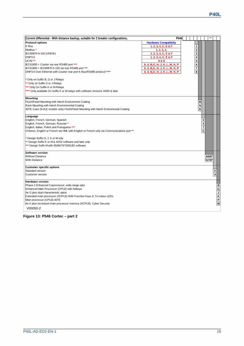
V00050-2
Current differential - With distance backup, suitable for 2 breaker configurations, P546 **Protocol optionsK-Bus 1Modbus * 2IEC60870-5-103 (VDEW) 3DNP3.0 4UCA2 ** 5IEC61850 + Courier via rear RS485 port *** 6IEC61850 + IEC60870-5-103 via rear RS485 port *** 7DNP3.0 Over Ethernet with Courier rear port K-Bus/RS485 protocol **** 8
* Only on Suffix B, G or J Relays
** Only on Suffix G or J Relays
*** Only On Suffix K or M Relays
**** Only available On Suffix K or M relays with software versions 44/54 & later
MountingFlush/Panel Mounting with Harsh Environment Coating MRack Mounting with Harsh Environmental Coating N40TE Case (9-2LE models only) Flush/Panel Mounting with Harsh Environmetal Coating R
LanguageEnglish, French, German, Spanish 0English, French, German, Russian * 5English, Italian, Polish and Portuguese *** 7Chinese, English or French via HMI, with English or French only via Communications port ** C
* Design Suffix G, J, K or M only** Design Suffix K or M & 42/52 software and later only*** Design Suffx M with 65/66/75/76/81/82 software
Software versionWithout Distance 4/6/8*With Distance 5/7/8*
Customer specific optionsStandard version 0Customer version A
Hardware versionPhase 2 Enhanced Coprocessor, wide range opto BEnhanced Main Processor (CPU2) with hotkeys GAs G plus dual characteristic optos JExtended main processor (XCPU2) With Function Keys & Tri-colour LEDs KMain processor (CPU3) 40TE PAs K plus increased main processor memory (XCPU3), Cyber Security M
6, A, B,G, H, J, K, L, M, N, P6, A, B,G, H, J, K, L, M, N, P6, A, B,G, H, J, K, L, M, N, P
5 & 61, 2, 3, 4, C, E & F1, 2, 3, 4, C, E & F
1, 2, 3, 4,1, 2, 3, 4, C, E & F
Hardware Compatibilty
Figure 13: P546 Cortec – part 2
P40L
20 P40L-AD-ED2-EN-1
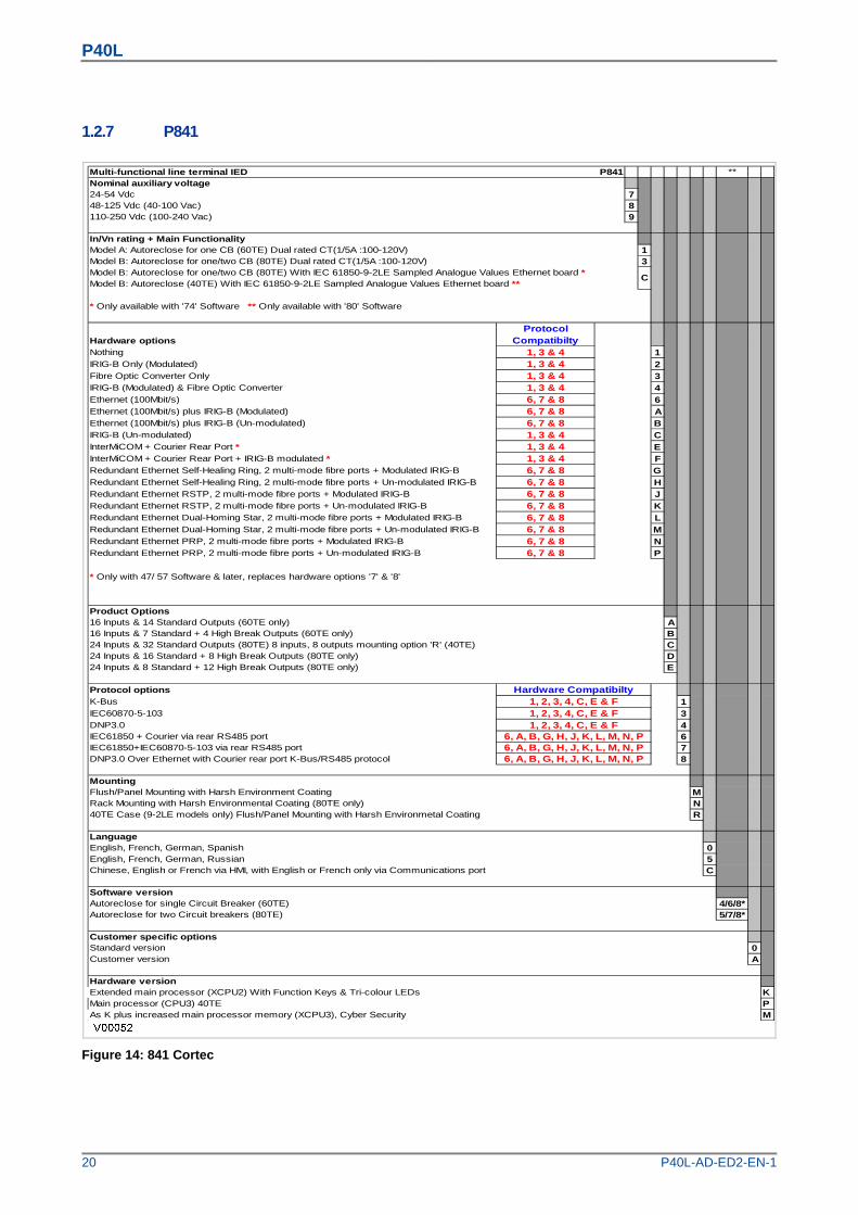
1.2.7 P841
Multi-functional line terminal IED P841 **Nominal auxiliary voltage24-54 Vdc 748-125 Vdc (40-100 Vac) 8110-250 Vdc (100-240 Vac) 9
In/Vn rating + Main FunctionalityModel A: Autoreclose for one CB (60TE) Dual rated CT(1/5A :100-120V) 1Model B: Autoreclose for one/two CB (80TE) Dual rated CT(1/5A :100-120V) 3Model B: Autoreclose for one/two CB (80TE) With IEC 61850-9-2LE Sampled Analogue Values Ethernet board *Model B: Autoreclose (40TE) With IEC 61850-9-2LE Sampled Analogue Values Ethernet board **
* Only available with '74' Software ** Only available with '80' Software
Hardware options
Protocol Compatibilty
Nothing 1, 3 & 4 1IRIG-B Only (Modulated) 1, 3 & 4 2Fibre Optic Converter Only 1, 3 & 4 3IRIG-B (Modulated) & Fibre Optic Converter 1, 3 & 4 4Ethernet (100Mbit/s) 6, 7 & 8 6Ethernet (100Mbit/s) plus IRIG-B (Modulated) 6, 7 & 8 AEthernet (100Mbit/s) plus IRIG-B (Un-modulated) 6, 7 & 8 BIRIG-B (Un-modulated) 1, 3 & 4 CInterMiCOM + Courier Rear Port * 1, 3 & 4 EInterMiCOM + Courier Rear Port + IRIG-B modulated * 1, 3 & 4 FRedundant Ethernet Self-Healing Ring, 2 multi-mode fibre ports + Modulated IRIG-B 6, 7 & 8 GRedundant Ethernet Self-Healing Ring, 2 multi-mode fibre ports + Un-modulated IRIG-B 6, 7 & 8 HRedundant Ethernet RSTP, 2 multi-mode fibre ports + Modulated IRIG-B 6, 7 & 8 JRedundant Ethernet RSTP, 2 multi-mode fibre ports + Un-modulated IRIG-B 6, 7 & 8 KRedundant Ethernet Dual-Homing Star, 2 multi-mode fibre ports + Modulated IRIG-B 6, 7 & 8 LRedundant Ethernet Dual-Homing Star, 2 multi-mode fibre ports + Un-modulated IRIG-B 6, 7 & 8 MRedundant Ethernet PRP, 2 multi-mode fibre ports + Modulated IRIG-B 6, 7 & 8 NRedundant Ethernet PRP, 2 multi-mode fibre ports + Un-modulated IRIG-B 6, 7 & 8 P
* Only with 47/ 57 Software & later, replaces hardware options '7' & '8'
Product Options16 Inputs & 14 Standard Outputs (60TE only) A16 Inputs & 7 Standard + 4 High Break Outputs (60TE only) B24 Inputs & 32 Standard Outputs (80TE) 8 inputs, 8 outputs mounting option 'R' (40TE) C24 Inputs & 16 Standard + 8 High Break Outputs (80TE only) D24 Inputs & 8 Standard + 12 High Break Outputs (80TE only) E
Protocol optionsK-Bus 1IEC60870-5-103 3DNP3.0 4IEC61850 + Courier via rear RS485 port 6IEC61850+IEC60870-5-103 via rear RS485 port 7DNP3.0 Over Ethernet with Courier rear port K-Bus/RS485 protocol 8
MountingFlush/Panel Mounting with Harsh Environment Coating MRack Mounting with Harsh Environmental Coating (80TE only) N40TE Case (9-2LE models only) Flush/Panel Mounting with Harsh Environmetal Coating R
LanguageEnglish, French, German, Spanish 0English, French, German, Russian 5Chinese, English or French via HMI, with English or French only via Communications port C
Software versionAutoreclose for single Circuit Breaker (60TE) 4/6/8*Autoreclose for two Circuit breakers (80TE) 5/7/8*
Customer specific optionsStandard version 0Customer version A
Hardware versionExtended main processor (XCPU2) With Function Keys & Tri-colour LEDs KMain processor (CPU3) 40TE PAs K plus increased main processor memory (XCPU3), Cyber Security M
Hardware Compatibilty
6, A, B, G, H, J, K, L, M, N, P6, A, B, G, H, J, K, L, M, N, P
1, 2, 3, 4, C, E & F1, 2, 3, 4, C, E & F1, 2, 3, 4, C, E & F
6, A, B, G, H, J, K, L, M, N, P
C
Figure 14: 841 Cortec

P40L
P40L-AD-ED2-EN-1 21
2 IEC 61850 EDITION 2
Many parts of the IEC 61850 standard have now been released as the second edition. This offers some significant enhancements including:
Improved interoperability
Many new Logical Nodes (LNs)
Better defined testing; it is now possible to perform off-line testing and simulation of functions
Edition 2 implementation requires use of version 3.2 of the IEC61850 configurator, which is installed with version 1.2 of MiCOM S1 Agile.
2.1 BACKWARD COMPATIBILITY
An Edition 1 IED can operate with an Edition 2 IEC 61850 system, provided that the Edition 1 IEDs do not subscribe to GOOSE messages with data objects or data attributes which are only available in Edition 2.
The following figure explains this concept:
V01056
Figure 15: Edition 2 system - backward compatibility
An Edition 2 IED cannot normally operate within an Edition 1 IEC 61850 system. An Edition 2 IED can work for GOOSE messaging in a mixed system, providing the client is compatible with Edition 2.
P40L
22 P40L-AD-ED2-EN-1
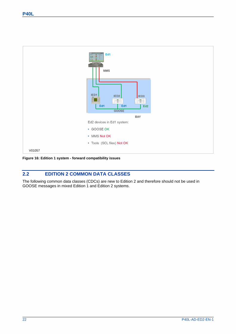
V01057
Figure 16: Edition 1 system - forward compatibility issues
2.2 EDITION 2 COMMON DATA CLASSES
The following common data classes (CDCs) are new to Edition 2 and therefore should not be used in GOOSE messages in mixed Edition 1 and Edition 2 systems.

P40L
P40L-AD-ED2-EN-1 23
Histogram (HST)
Visible string status (VSS)
Object reference setting (ORG)
Enumerated Status (ENS)
Controllable enumerated status (ENC)
Controllable analogue process value (APC)
Binary controlled analogue process value (BAC)
Enumerated status setting (ENG)
Time setting group (TSG)
Currency setting group (CUG)
Visible string setting (VSG)
Curve shape setting (CSG)
Of these, only ENS and ENC types are available from a MiCOM P40 IED when publishing GOOSE messages, so Data Objects using these Common Data Classes should not be published in mixed Edition 1 and Edition 2 systems.
For compatibility between Edition 1 and Edition 2 IEDs, SCL files using SCL schema version 2.1 must be used. For a purely Edition 2 system, use the schema version 3.1.
2.3 STANDBY PROTECTION FUNCTION REDUNDANCY
With digital substation architectures, measurements can be shared freely on the process bus across the substation and between different devices without any additional wiring. This is because there are no longer any electrical connections to instruments transformers that restrict the location of IEDs.
The new IEC 61850 Edition 2 test modes enable the introduction of standby protection IEDs at any location within the substation, which has access to both station and process buses. In the case of failure, these devices can temporarily replace the protection functions inside other IEDs.

P40L
24 P40L-AD-ED2-EN-1
V01059
Figure 17: Example of Standby IED
See the example below. If a failure occurs in the Bay 1 protection IED (MP2), we could disable this device and activate a standby protection IED to replace its functionality.
Figure 18: Standby IED Activation Process
The following sequence would occur under this scenario:
1 During the installation phase, a spare standby IED is installed in the substation. This can remain inactive, until it is needed to replace functions in one of several bays. The device is connected to the process bus, but does not have any subscriptions enabled.
2 If a failure occurs (in this example, bay 1), first isolate the faulty device by disabling its process bus and station bus interfaces. You do this by turning off the attached network interfaces.

P40L
P40L-AD-ED2-EN-1 25
3 Retrieve the configuration that the faulty device normally uses, and load this into the standby redundant IED.
4 Place the IED into the “Test Blocked” mode, as defined in IEC 61850-7-4 Edition Two. This allows test signals to be injected into the network, which will check that the configuration is correct. GOOSE signals issued by the device will be flagged as “test” so that subscribing switchgear controllers know not to trip during this testing. In this way the protection can be tested all the way up to the switchgear control merging units without having to operate primary circuit breakers, or by carrying out any secondary injection.
5 Take the standby IED out of “Test-Blocked” mode and activate it so that it now replaces the protection functions that were disabled from the initial device failure.
The standby IED reduces downtime in the case of device failure, as protection functions can be restored quickly before the faulted device is replaced.
P40L
26 P40L-AD-ED2-EN-1
3 SIMPLE NETWORK MANAGEMENT PROTOCOL
3.1 INTRODUCTION
Simple Network Management Protocol (SNMP) is a network protocol designed to manage devices in an IP network. The MiCOM P40 Modular products can provide up to two SNMP interfaces on Ethernet models; one to the IED’s Main Processor for device level status information, and another directly to the redundant Ethernet board (where applicable) for specific Ethernet network level information.
Two versions of SNMP are supported: Version 2c, and a secure implementation of version 3 that includes cybersecurity. Only the Main Processor SNMP interface supports Version 3.
3.2 SNMP MANAGEMENT INFORMATION BASES (MIBS)
SNMP uses a Management Information Base (MIB), which contains information about parameters to supervise. The MIB format is a tree structure, with each node in the tree identified by a numerical Object Identifier (OID). Each OID identifies a variable that can be read using SNMP with the appropriate software. The information in the MIB is standardized.
Each device in a network (workstation, server, router, bridge, etc.) maintains a MIB that reflects the status of the managed resources on that system, such as the version of the software running on the device, the IP address assigned to a port or interface, the amount of free hard drive space, or the number of open files. The MIB does not contain static data, but is instead an object-oriented, dynamic database that provides a logical collection of managed object definitions. The MIB defines the data type of each managed object and describes the object.
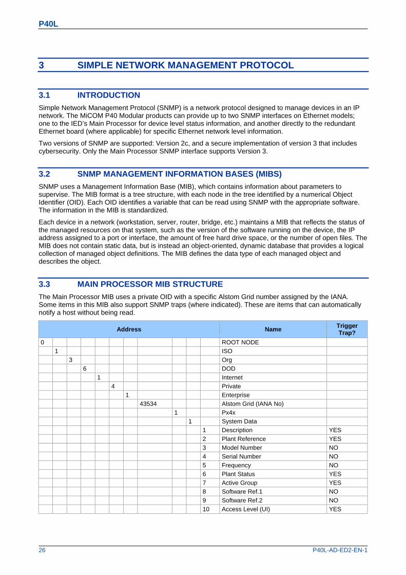
3.3 MAIN PROCESSOR MIB STRUCTURE
The Main Processor MIB uses a private OID with a specific Alstom Grid number assigned by the IANA. Some items in this MIB also support SNMP traps (where indicated). These are items that can automatically notify a host without being read.
Address Name Trigger Trap?
0 ROOT NODE
1 ISO
3 Org
6 DOD
1 Internet
4 Private
1 Enterprise
43534 Alstom Grid (IANA No)
1 Px4x
1 System Data
1 Description YES
2 Plant Reference YES
3 Model Number NO
4 Serial Number NO
5 Frequency NO
6 Plant Status YES
7 Active Group YES
8 Software Ref.1 NO
9 Software Ref.2 NO
10 Access Level (UI) YES
P40L
P40L-AD-ED2-EN-1 27
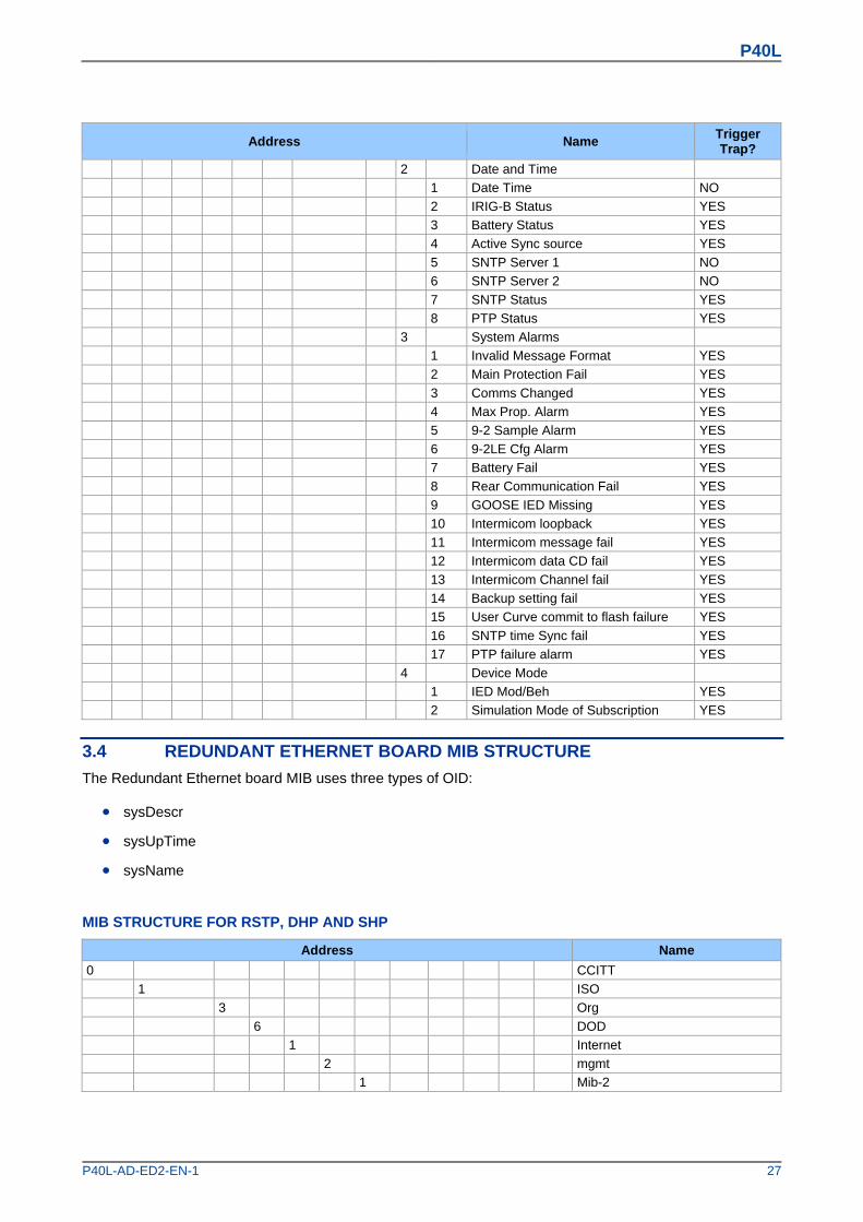
Address Name Trigger Trap?
2 Date and Time
1 Date Time NO
2 IRIG-B Status YES
3 Battery Status YES
4 Active Sync source YES
5 SNTP Server 1 NO
6 SNTP Server 2 NO
7 SNTP Status YES
8 PTP Status YES
3 System Alarms
1 Invalid Message Format YES
2 Main Protection Fail YES
3 Comms Changed YES
4 Max Prop. Alarm YES
5 9-2 Sample Alarm YES
6 9-2LE Cfg Alarm YES
7 Battery Fail YES
8 Rear Communication Fail YES
9 GOOSE IED Missing YES
10 Intermicom loopback YES
11 Intermicom message fail YES
12 Intermicom data CD fail YES
13 Intermicom Channel fail YES
14 Backup setting fail YES
15 User Curve commit to flash failure YES
16 SNTP time Sync fail YES
17 PTP failure alarm YES
4 Device Mode
1 IED Mod/Beh YES
2 Simulation Mode of Subscription YES
3.4 REDUNDANT ETHERNET BOARD MIB STRUCTURE
The Redundant Ethernet board MIB uses three types of OID:
sysDescr
sysUpTime
sysName
MIB STRUCTURE FOR RSTP, DHP AND SHP
Address Name
0 CCITT
1 ISO
3 Org
6 DOD
1 Internet
2 mgmt
1 Mib-2

P40L
28 P40L-AD-ED2-EN-1
Address Name
1 sys
1 sysDescr
3 sysUpTime
4 sysName
Remote Monitoring
16 RMON
1 statistics
1 etherstat
1 etherStatsEntry
9 etherStatsUndersizePkts
10 etherStatsOversizePkts
12 etherStatsJabbers
13 etherStatsCollisions
14 etherStatsPkts64Octets
15 etherStatsPkts65to127Octets
16 etherStatsPkts128to255Octets
17 etherStatsPkts256to511Octets
18 etherStatsPkts512to1023Octets
MIB STRUCTURE FOR PRP
Address Name
0 ITU
1 ISO
0 Standard
62439 IECHighavailibility
3 PRP
1 linkRedundancyEntityObjects
0 lreConfiguration
0 lreConfigurationGeneralGroup
1 lreManufacturerName
2 lreInterfaceCount
1 lreConfigurationInterfaceGroup
0 lreConfigurationInterfaces
1 lreInterfaceConfigTable
1 lreInterfaceConfigEntry
1 lreInterfaceConfigIndex
2 lreRowStatus
3 lreNodeType
4 lreNodeName
5 lreVersionName
6 lreMacAddressA
7 lreMacAddressB
8 lreAdapterAdminStateA
9 lreAdapterAdminStateB
10 lreLinkStatusA
11 lreLinkStatusB
12 lreDuplicateDiscard
13 lreTransparentReception
14 lreHsrLREMode
15 lreSwitchingEndNode

P40L
P40L-AD-ED2-EN-1 29
Address Name
16 lreRedBoxIdentity
17 lreSanA
18 lreSanB
19 lreEvaluateSupervision
20 lreNodesTableClear
21 lreProxyNodeTableClear
3.5 ACCESSING THE MIB
Various SNMP client software tools can be used. Alstom Grid recommends using an SNMP MIB browser, which can perform the basic SNMP operations such as GET, GETNEXT and RESPONSE.
Note: There are two IP addresses visible when communicating with the Redundant Ethernet Card via the fibre optic ports: Use the one for the IED itself to the Main Processor SNMP interface, and use the one for the on-board Ethernet switch to access the Redundant Ethernet Board SNMP interface. See the configuration chapter for more information.
3.6 MAIN PROCESSOR SNMP CONFIGURATION
You configure the main processor SNMP interface using the HMI panel. Two different versions are available; SNMPv2c and SNMPv3:
To enable the main processor SNMP interface:
1 Select the COMMUNICATIONS column and scroll to the SNMP PARAMETERS heading
2 You can select either v2C, V3 or both. Selecting None will disable the main processor SNMP interface.
SNMP TRAP CONFIGURATION:
SNMP traps allow for unsolicited reporting between the IED and up to two SNMP managers with unique IP addresses. The device MIB details what information can be reported using Traps. To configure the SNMP Traps:
1 Move down to the cell Trap Dest. IP 1 and enter the IP address of the first destination SNMP manager. Setting this cell to 0.0.0.0 disables the first Trap interface.
2 Move down to the cell Trap Dest. IP 2 and enter the IP address of the second destination SNMP manager. Setting this cell to 0.0.0.0 disables the Second Trap interface.
SNMPV3 SECURITY CONFIGURATION
SNMPv3 provides a higher level of security via authentication and privacy protocols. The IED adopts a secure SNMPv3 implementation with a user-based security model (USM).
Authentication is used to check the identity of users, privacy allows for encryption of SNMP messages. Both are optional, however you must enable authentication in order to enable privacy. To configure these security options:
1 If SNMPv3 has been enabled, set the Security Level setting. There are three levels; without authentication and without privacy (noAuthNoPriv), with authentication but without privacy (authNoPriv), and with authentication and with privacy (authPriv).
2 If Authentication is enabled, use the Auth Protocol setting to select the authentication type. There are two options: HMAC-MD5-96 or HMAC-SHA-96.

P40L
30 P40L-AD-ED2-EN-1
3 Using the Auth Password setting, enter the 8-character password to be used by the IED for authentication.
4 If privacy is enabled, use the Encrypt Protocol setting to set the 8-character password that will be used by the IED for encryption.
SNMPV2C SECURITY CONFIGURATION
SNMPv2c implements authentication between the master and agent using a parameter called the Community Name. This is effectively the password but it is not encrypted during transmission (this makes it inappropriate for some scenarios in which case version 3 should be used instead). To configure the SNMP 2c security:
1 If SNMPv2c has been enabled, use the Community Name setting to set the password that will be used by the IED and SNMP manager for authentication. This may be between one and 8 characters.
P40L
P40L-AD-ED2-EN-1 31
4 IEEE 1588 PRECISION TIME PROTOCOL
The MiCOM P40 modular products support the IEEE C37.238 (Power Profile) of IEEE 1588 Precision Time Protocol (PTP) as a slave-only clock. This can be used to replace or supplement IRIG-B and SNTP time synchronisation so that the IED can be synchronised using Ethernet messages from the substation LAN without any additional physical connections being required.
4.1 ACCURACY AND DELAY CALCULATION
A time synchronisation accuracy of within 5 ms is possible. Both peer-to-peer or end-to-end mode delay measurement can be used.
In peer-to-peer mode, delays are measured between each link in the network and are compensated for. This provides greater accuracy, but requires that every device between the Grand Master and Slaves supports the peer-to-peer delay measurement.
In end-to-end mode, delays are only measured between each Grand Master and Slave. The advantage of this mode is that the requirements for the switches on the network are lower; they do not need to independently calculate delays. The main disadvantage is that more inaccuracy is introduced, because the method assumes that forward and reverse delays are always the same, which may not always be correct.
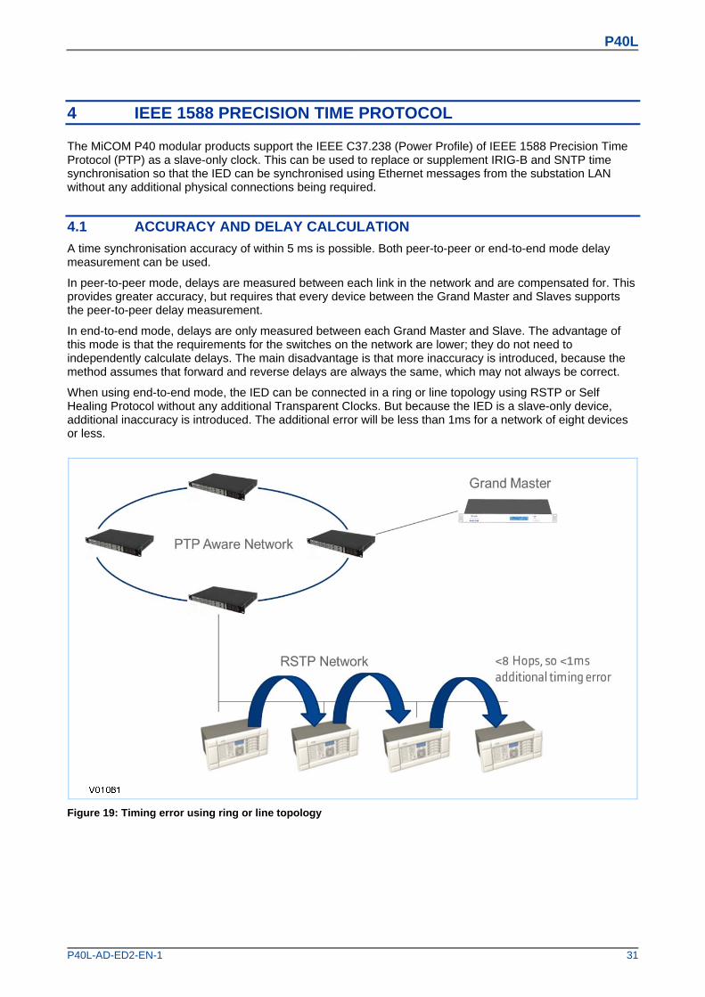
When using end-to-end mode, the IED can be connected in a ring or line topology using RSTP or Self Healing Protocol without any additional Transparent Clocks. But because the IED is a slave-only device, additional inaccuracy is introduced. The additional error will be less than 1ms for a network of eight devices or less.
Figure 19: Timing error using ring or line topology

P40L
32 P40L-AD-ED2-EN-1
4.2 PTP DOMAINS
PTP traffic can be segregated into different domains using Boundary Clocks. These allow different PTP clocks to share the same network while maintaining independent synchronisation within each grouped set.

P40L
P40L-AD-ED2-EN-1 33
5 NEW TESTING FUNCTIONALITY
5.1 USING IEC 61850 EDITION 2 TEST MODES
In a conventional substation, functionality typically resides in a single device. It is usually easy to physically isolate these functions, as the hardwired connects can simply be removed. Within a digital substation architecture however, functions may be distributed across many devices. This makes isolation of these functions difficult, because there are no physical wires that can be disconnected on a Ethernet network. Logical isolation of the various functions is therefore necessary.
With devices that support IEC 61850 Edition 2, it is possible to use a test mode to conduct online testing, which helps with the situation. The advantages of this are as follows:
The device can be placed into a test mode, which can disable the relay outputs when testing the device with test input signals.
Specific protection and control functions can be logically isolated.
GOOSE messages can be tagged so that receiving devices can recognise they are test signals.
An IED receiving simulated GOOSE or Sampled Value messages from test devices can differentiate these from normal process messages, and be configured to respond appropriately.
5.1.1 IED TEST MODE BEHAVIOUR
Test modes define how the device responds to test messages, and whether the relay outputs are activated or not. You can select the mode of operation by:
Using the front panel HMI, with the setting IED Test Mode under the COMMISSION TESTS column.
Using an IEC 61850 control service to System/LLN0.Mod
Using an opto-input via PSL with the signal Block Contacts (DDB 862)
The following table summarises the IED behaviour under the different modes:
IED Test Mode Setting Result
Disabled Normal IED behaviour
Test
Protection remains enabled Output from the device is still active IEC 61850 message output has the 'quality' parameter set to 'test' The device only responds to IEC61850 MMS messages from the client with the
'test' flag set
Contacts Blocked
Protection remains enabled Output from the device is disabled IEC 61850 message output has quality set to ‘test’ The device only responds to IEC 61850 MMS messages from the client with
the 'test' flag set
Setting the Test or Contacts Blocked mode puts the whole IED into test mode. The IEC 61850 data object Beh in all Logical Nodes (except LPHD and any protection Logical Nodes that have Beh = 5 (off) due to the function being disabled) will be set to 3 (test) or 4 (test/blocked) as applicable.

P40L
34 P40L-AD-ED2-EN-1
5.1.2 SAMPLED VALUE TEST MODE BEHAVIOUR
The SV Test Mode defines how the device responds to test sampled value messages. You can select the mode of operation by using the front panel HMI, with the setting SV Test Mode under the IEC 61850-9.2LE column.
The following table summarises the behaviour for sampled values under the different modes:
SV Test Mode Setting Result
Disabled
Normal IED behaviour All sampled value data frames received with an IEC 61850 Test quality bit set
are treated as invalid The IED will display the measurement values for sampled values with the
Simulated flag set but the protection elements within the IED will be blocked
Enabled All sampled value data frames received are treated as good, no matter if they have an IEC 61850-9-2 Simulated flag set or not
5.2 SIMULATED INPUT BEHAVIOUR
Simulated GOOSE messages and sampled value streams can be used during testing.
The Subscriber Sim setting in the COMMISSION TESTS column controls whether a device listens to simulated signals or to real ones. An IEC 61850 control service to System/LPHD.Sim can also be used to change this value.
The device may be presented with both real signals and test signals. An internal state machine is used to control how the device switches between signals:
The IED will continue subscribing to the ‘real’ GOOSE1 (in green) until it receives the first simulated GOOSE 1 (in red). This will initiate subscription changeover.
After changeover to this new state, the IED will continue to subscribe to the simulated GOOSE 1 message (in red). Even if this simulated GOOSE 1 message disappears, the real GOOSE 1 message (in green) will still not be processed. This means all Virtual Inputs derived from the GOOSE 1 message will go to their default state.
The only way to bring the IED out of this state is to set the Subscriber Sim setting back to False. The IED will then immediately stop processing the simulated messages and start processing real messages again.
During above steps, IED1 will continuously process the real GOOSE 2 and GOOSE 3 messages as normal because it has not received any simulated messages for these that would initiate a changeover.
The process is represented in the following figure:

P40L
P40L-AD-ED2-EN-1 35
Figure 20: Simulated input behaviour
5.3 TESTING EXAMPLES USING IEC 61850 ED2
These examples show how you test the IED with and without simulated values. Depending on the IED Test Mode, it may respond by operating plant (for example by tripping the circuit breaker) or it may not operate plant.
5.3.1 PROCEDURE FOR TESTING WITH REAL VALUES WITHOUT OPERATING PLANT
1 Set device into 'Contacts Blocked' Mode Select COMMISSION TESTS IED Test Mode Contacts Blocked
2 Confirm new behaviour has been enabled View COMMISSION TESTS IED Mod/Beh, and check that it shows test-blocked
3 Set device into Simulation Listening Mode Select COMMISSION TESTS Subscriber Sim = Disabled
4 If using sampled values set the sampled values test mode Select IEC 61850-9.2LE SV Test Mode Disabled
5 Inject real signals using a test device connected to the merging units. The device will continue to listen to ‘real’ GOOSE messages and ignore simulated messages received.
6 Verify function based on test signal outputs Binary outputs (e.g. CB trips) will not operate. All transmitted GOOSE and MMS data items will be tagged with the 'quality' parameter set to 'test', so that the receiver understands that they have been issued by a device under test and can respond accordingly. This is summarised in the following diagram

P40L
36 P40L-AD-ED2-EN-1
Figure 21: Test example 1
5.3.2 PROCEDURE FOR TESTING WITH SIMULATED VALUES WITHOUT OPERATING PLANT
1 Set device into Contacts Blocked Mode Select COMMISSION TESTS IED Test Mode Contacts Blocked
2 Confirm new behaviour has been enabled View COMMISSION TESTS IED Mod/Beh, and check that it shows test-blocked
3 Set device into Simulation Listening Mode Select COMMISSION TESTS Subscriber Sim = Enabled
4 If using sampled values set the sampled values test mode Select IEC 61850-9.2LE SV Test Mode Enabled
5 Inject simulated signals using a test device connected to the Ethernet network. The device will continue to listen to ‘real’ GOOSE messages until a simulated message is received. Once the simulated messages are received, the corresponding ‘real’ messages are ignored until the device is taken out of test mode. Each message is treated separately, but sampled values are considered as a single message.
6 Verify function based on test signal outputs Binary outputs (e.g. CB trips) will not operate. All transmitted GOOSE and MMS data items will be tagged with the 'quality' parameter set to 'test', so that the receiver understands that they have been issued by a device under test and can respond accordingly. This is summarised in the following diagram

P40L
P40L-AD-ED2-EN-1 37
Figure 22: Test example 2
5.3.3 PROCEDURE FOR TESTING WITH SIMULATED VALUES TO OPERATE PLANT
1 Set device into Contacts Blocked Mode Select COMMISSION TESTS IED Test Mode Test
2 Confirm new behaviour has been enabled View COMMISSION TESTS IED Mod/Beh, and check that it shows Test
3 Set device into Simulation Listening Mode Select COMMISSION TESTS Subscriber Sim = Enabled
4 If using sampled values set the sampled values test mode Select IEC 61850-9.2LE SV Test Mode Enabled
5 Inject simulated signals using a test device connected to the Ethernet network. The device will continue to listen to ‘real’ GOOSE messages until a simulated message is received. Once the simulated messages are received, the corresponding ‘real’ messages are ignored until the device is taken out of IED test mode. Each message is treated separately, but sampled values are considered as a single message.
6 Verify function based on test signal outputs. Binary outputs (e.g. CB trips) will operate as normal. All transmitted GOOSE and MMS data items will be tagged with the 'quality' parameter set to 'test', so that the receiver understands that they have been issued by a device under test and can respond accordingly. This is summarised in the following diagram:

P40L
38 P40L-AD-ED2-EN-1
Figure 23: Test example 3
5.3.4 CONTACT TEST
The Apply Test command in this cell is used to change the state of the contacts set for operation.
If the device has been put into 'Contact Blocked' mode using an input signal (via the Block Contacts DDB signal) then the Apply Test command will not execute. This is to prevent a device that has been blocked by an external process having its contacts operated by a local operator using the HMI.
If the Block Contacts DDB is not set and the Apply Test command in this cell is issued, contacts change state and the command text on the LCD changes to No Operation. The contacts remain in the Test state until reset by issuing the Remove Test command. The command text on the LCD shows No Operation after the Remove Test command has been issued.
Note: When the IED Test Mode cell is set to Contacts Blocked, the Relay O/P Status cell does not show the current status of the output relays so cannot be used to confirm operation of the output relays. Therefore it is necessary to monitor the state of each contact in turn.

P40L
P40L-AD-ED2-EN-1 39
6 DATE AND TIME CONFIGURATION
6.1 USING AN SNTP SIGNAL
When using SNTP to maintain the clock, the IED must first be connected to the SNTP server, which should be energized and functioning.
1 In the DATE AND TIME column, check that either the Primary Source or Secondary Source setting is set to SNTP.
2 Ensure that the IED is receiving valid time synchronisation messages by checking that the SNTP Status cell reads Server 1 OK or Server 2 OK.
3 Check that the Act. Time Source cell reads SNTP. This indicates that the IED is using PTP as the source for its time. Note that If IRIG-B or PTP have been selected as the Primary Source, these must first be disconnected before the device can switch to SNTP as the active source.
4 Once the IED is using SNTP as the active time source, adjust the time offset of the universal coordinated time on the SNTP Server equipment, so that local time is displayed.
5 Check that the time, date and month are correct in the Date/Time cell.
6.2 USING AN IRIG-B SIGNAL
When using IRIG-B to maintain the clock, the IED must first be connected to the timing source equipment (usually a P594), which should be energized and functioning.
1 In the DATE AND TIME column, check that either the Primary Source or Secondary Source setting is set to IRIG-B.
2 Ensure the IED is receiving the IRIG-B signal by checking that IRIG-B Status cell reads Active.
3 Check that the Act. Time Source cell reads IRIG-B. This indicates that the IED is using IRIG-B as the source for its time. Note that if PTP or SNTP have been selected as the Primary Source, these must first be disconnected before the device can switch to IRIG-B as the active source.
4 Once the IRIG-B signal is confirmed as the active time source, adjust the time offset of the universal coordinated time (satellite clock time) on the satellite clock equipment, so that local time is displayed.
5 Check that the time, date and month are correct in the Date/Time cell. The IRIG-B signal does not contain the current year so this also needs to be set manually in this cell.
6 If the auxiliary supply fails, the time and date are maintained by the auxiliary battery. Therefore, when the auxiliary supply is restored, you should not have to set the time and date again. To test this, remove the IRIG-B signal, and then remove the auxiliary supply. Leave the device de-energized for approximately 30 seconds. On re-energization, the time should be correct.
7 Reconnect the IRIG-B signal.
6.3 USING AN IEEE 1588 PTP SIGNAL
When using IEEE 1588 PTP to maintain the clock, the IED must first be connected to the PTP Grandmaster, which should be energized and functioning.
1 In the DATE AND TIME column, check that either the Primary Source or Secondary Source setting is set to PTP.
2 Set the setting Domain Number setting. The domain defines which clocks the IED will use for synchronisation. Therefore this number must match the domain used by the other clocks on the network.

P40L
40 P40L-AD-ED2-EN-1
3 Ensure that the IED is receiving valid time synchronisation messages by checking that the PTP Status cell reads Valid Master.
4 Check that Act. Time Source cell reads PTP. This indicates that the IED is using PTP as the source for its time. Note that If IRIG-B or SNTP have been selected as the Primary Source, these must first be disconnected before the device can switch to PTP as the active source.
5 Once the IED is using PTP as the active time source, adjust the time offset of the universal coordinated time on the Master Clock equipment, so that local time is displayed.
6 Check that the time, date and month are correct in the Date/Time cell.
6.4 WITHOUT A TIMING SOURCE SIGNAL
If the time and date is not being maintained by an IRIG-B, PTP or SNTP signal, in the DATE AND TIME column, ensure that both the Primary Source and Secondary Source are set to NONE.
1 Check that Act. Time Source cell reads Free Running.
2 Set the date and time to the correct local time and date using the Date/Time cell or the serial protocol.
3 If the auxiliary supply fails, the time and date are maintained by the auxiliary battery. Therefore, when the auxiliary supply is restored, you should not have to set the time and date again. To test this, remove the auxiliary supply. Leave the device de-energized for approximately 30 seconds. On re-energization, the time should be correct.

P40L
P40L-AD-ED2-EN-1 41
7 NEW TECHNICAL SPECIFICATIONS
Rear Ethernet port using CAT 5/6/7 wiring
Main Use Substation Ethernet communications
Standard IEEE 802.3 10BaseT/100BaseTX
Connector RJ45
Cable type Screened twisted pair (STP)
Isolation 1.5 kV
Supported Protocols IEC 61850 Edition 2, DNP3.0 OE, IEEE 1588 PTP, SNMP
Constraints Maximum cable length 100 m
Rear Ethernet port using fibre-optic cabling
Main Use Substation Ethernet communications
Connector IEC 874-10 BFOC 2.5 –(ST®) (1 each for Tx and Rx)
Standard IEEE 802.3 100 BaseFX
Fibre type Multimode 50/125 µm or 62.5/125 µm
Supported Protocols IEC 61850, DNP3.0 OE, IEEE 1588 PTP, SNMP
Optional Redundancy Protocols Supported
Rapid spanning tree protocol (RSTP)
Self-healing protocol (SHP)
Dual homing protocol (DHP)
Parallel Redundancy Protocol (PRP)
Wavelength 1300 nm

P40L
42 P40L-AD-ED2-EN-1
8 SETTINGS AND RECORDS
New settings for this version of the product range are as follows: MENU TEXT Col Row Default Setting Available Setting
Description
DATE and TIME 08 00 This column contains Date and Time stamp settings
Primary Source 08 80 PTP
0 = IRIG-B 1 = None 2 = PTP 3 = SNTP
Sets the primary time synchronisation source
Secondary Source 08 90 None
0 = IRIG-B 1 = None 2 = PTP 3 = SNTP
Sets the secondary time synchronisation source Domain Number 08 0F 0 0 to 127 step 1 Assigns the PTP domain number. A domain is grouping of PTP clocks that synchronise to each other on a network. This provides a way of implementing independent synchronisation of PTP clocks on a shared network
Act. Time Source 08 10
0 = IRIG-B 1 = Free Running 2 = PTP 3 = SNTP
Displays the active time synchronisation source being used. ‘Free Running’ means the IED is not synchronised with any normal time-server, including IRIG-B, PTP or SNTP. The IED relies solely on its internal clock.
IRIG-B Status 08 11 0 = Card Not Fitted, 1 = Card Failed, 2 = Signal Healthy, 3 = No Signal
Displays the status of IRIG-B
PTP Status 08 12
0 = Disabled 1 = No Master Found 2 = Illegal Master 3 = Valid master
IEC61850 or DNP3.0 over Ethernet versions only. Displays the status of PTP time synchronisation No Master Found = No PTP master can be found, the IED has not received a valid ‘Announce’ message. Illegal Master = Master clock is not valid, typically this will occur when the clock is not using the correct epoch Valid Master = At least valid one master clock is available
SNTP Status 08 13
0 = Disabled, 1 = Trying server 1, 2 = Trying server 2, 3 = Server 1 OK, 4 = Server 2 OK, 5 = No response, 6 = No valid clock
IEC61850 or DNP3.0 over Ethernet versions only. Displays information about the SNTP time synchronisation status. COMMUNICATIONS 0E 00 This column contains general communications settings
Class 0 Poll 0E 16 Running Counters 0 = Running Counters 1 = Frozen Counters
Used for DNP serial only. When set the cell to “Running Counters”, the IED will only report the static counters (object 20) in class 0 responses. Otherwise if set to “Frozen Counters”, the IED will only report the frozen counters (object 21) in class 0 responses.
Class 0 Poll 0E B5 Running Counters 0 = Running Counters 1 = Frozen Counters
P40L
P40L-AD-ED2-EN-1 43
MENU TEXT Col Row Default Setting Available Setting
Description
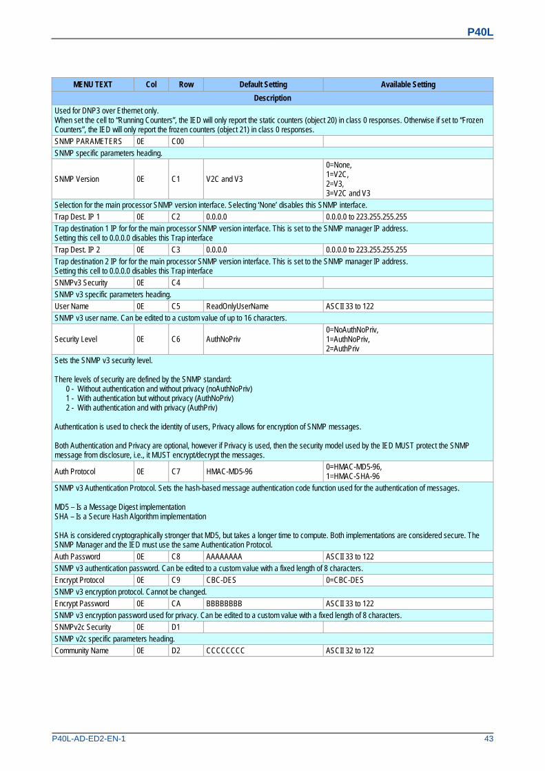
Used for DNP3 over Ethernet only. When set the cell to “Running Counters”, the IED will only report the static counters (object 20) in class 0 responses. Otherwise if set to “Frozen Counters”, the IED will only report the frozen counters (object 21) in class 0 responses. SNMP PARAMETERS 0E C00 SNMP specific parameters heading.
SNMP Version 0E C1 V2C and V3
0=None, 1=V2C, 2=V3, 3=V2C and V3
Selection for the main processor SNMP version interface. Selecting ‘None’ disables this SNMP interface. Trap Dest. IP 1 0E C2 0.0.0.0 0.0.0.0 to 223.255.255.255 Trap destination 1 IP for for the main processor SNMP version interface. This is set to the SNMP manager IP address. Setting this cell to 0.0.0.0 disables this Trap interface Trap Dest. IP 2 0E C3 0.0.0.0 0.0.0.0 to 223.255.255.255 Trap destination 2 IP for for the main processor SNMP version interface. This is set to the SNMP manager IP address. Setting this cell to 0.0.0.0 disables this Trap interface SNMPv3 Security 0E C4 SNMP v3 specific parameters heading. User Name 0E C5 ReadOnlyUserName ASCII 33 to 122 SNMP v3 user name. Can be edited to a custom value of up to 16 characters.
Security Level 0E C6 AuthNoPriv 0=NoAuthNoPriv, 1=AuthNoPriv, 2=AuthPriv
Sets the SNMP v3 security level. There levels of security are defined by the SNMP standard: 0 - Without authentication and without privacy (noAuthNoPriv) 1 - With authentication but without privacy (AuthNoPriv) 2 - With authentication and with privacy (AuthPriv) Authentication is used to check the identity of users, Privacy allows for encryption of SNMP messages. Both Authentication and Privacy are optional, however if Privacy is used, then the security model used by the IED MUST protect the SNMP message from disclosure, i.e., it MUST encrypt/decrypt the messages.
Auth Protocol 0E C7 HMAC-MD5-96 0=HMAC-MD5-96, 1=HMAC-SHA-96
SNMP v3 Authentication Protocol. Sets the hash-based message authentication code function used for the authentication of messages. MD5 – Is a Message Digest implementation SHA – Is a Secure Hash Algorithm implementation SHA is considered cryptographically stronger that MD5, but takes a longer time to compute. Both implementations are considered secure. The SNMP Manager and the IED must use the same Authentication Protocol.
Auth Password 0E C8 AAAAAAAA ASCII 33 to 122 SNMP v3 authentication password. Can be edited to a custom value with a fixed length of 8 characters. Encrypt Protocol 0E C9 CBC-DES 0=CBC-DES SNMP v3 encryption protocol. Cannot be changed. Encrypt Password 0E CA BBBBBBBB ASCII 33 to 122 SNMP v3 encryption password used for privacy. Can be edited to a custom value with a fixed length of 8 characters. SNMPv2c Security 0E D1 SNMP v2c specific parameters heading. Community Name 0E D2 CCCCCCCC ASCII 32 to 122

P40L
44 P40L-AD-ED2-EN-1
MENU TEXT Col Row Default Setting Available Setting
Description
SNMP v2c community name, used for authentication between the SNMP manager and the IED. Can be edited to a custom value of 1-8 characters. The community name setting must be the same in both the SNMP Manager and the IED. COMMISSION TESTS 0F 00 This column contains commissioning test settings IED Test mode 0F 0D The IED Test Mode menu cell is used to allow online testing to be performed on the IED without operation of the trip contacts. It also enables a facility to directly test the output contacts by applying menu controlled test signals. This setting influences the processing of GOOSE and control service frames with an IEC61850 Test mode flag. To select test mode the IED Test Mode menu cell should be set to ‘Test’, which takes the IED out of service. It also causes an alarm condition to be recorded and the yellow ‘Out of Service’ LED to illuminate. In IEC 60870-5-103 builds changes the Cause of Transmission, COT, to Test Mode. In IED Test Mode, only GOOSE messages and control service commands with a quality flat set to "test" will be processed as valid . To enable testing of output contacts the IED Test Mode cell should be set to Contacts Blocked. This blocks the protection from operating the contacts and enables the test pattern and contact test functions which can be used to manually operate the output contacts. This mode also blocks maintenance, counters and freezes any information stored in the Circuit Breaker Condition column. Also in IEC 60870-5-103 builds changes the Cause of Transmission, COT, to Test Mode. In Contacts Blocked Mode, only GOOSE messages and control service commands with a quality flat set to "test" will be processed as valid. Once testing is complete the cell must be set back to ‘Disabled’ to restore the IED back to service The following IEC 61850 Mode definitions apply for the different settings: 0 = Disabled Mod = 1 (On) 1 = Test Mod = 3 (Test) 2 = Contacts Blocked Mod = 4 (Test/blocked) Note: The cell ‘Test Mode’ used in software prior to IEC 61850 edition 2 has been renamed as ‘IED Test Mode’ IED Mod/Beh 0F 1E Indicates the current Mod/Beh status of whole IED Subscriber Sim 0F 1F Disabled Used to enable/disable the 'subscriber simulation' feature, for Sampled Values and GOOSE subscriptions IEC 61850-9.2LE 18 00 This column contains all the configure/setting measurement parameters relative to IEC61850-9-2LE. SV Test Mode 18 04 Disabled Disabled, Enabled This setting is used for processing Sampled Value frames with an IEC 61850 Test mode flag. This setting is common to all SV Logical Nodes configured in the IED. Disabled: all channel data frames received with an IEC 61850 Test flag are treated as invalid. The IED blocks relevant protection functions Enabled: all channel data frames received with an IEC 61850 Test flag are treated as good so all protection functions remain active. Note: The cell ‘9.2 Mode’ used in software prior to IEC 61850 edition 2 has been renamed as ‘SV Test Mode’ LN1 FramesRcvd 18 61 1 Count of 9-2LE frames received by the LN LN2 FramesRcvd 18 62 0 Count of 9-2LE frames received by the LN LN3 FramesRcvd 18 63 0 Count of 9-2LE frames received by the LN LN4 FramesRcvd 18 64 0 Count of 9-2LE frames received by the LN LN5 FramesRcvd 18 65 0 Count of 9-2LE frames received by the LN LN6 FramesRcvd 18 66 0 Count of 9-2LE frames received by the LN
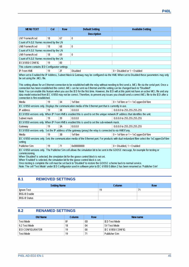
P40L
P40L-AD-ED2-EN-1 45
MENU TEXT Col Row Default Setting Available Setting
Description
LN7 FramesRcvd 18 67 0 Count of 9-2LE frames received by the LN LN8 FramesRcvd 18 68 0 Count of 9-2LE frames received by the LN LN9 FramesRcvd 18 69 0 Count of 9-2LE frames received by the LN IEC61850 CONFIG 19 00 This column contains IED Configurator settings IP From HMI 19 2F Disabled 0 = Disabled or 1 = Enabled When set to Enabled the IP Address, Subnet Mask & Gateway may be configured via the HMI. When set to Disabled these parameters may only be set using the .MCL file. This setting allows for an Ethernet connection to be established with the relay without needing to first send a .MCL file via the serial port. Once a connection has been established the correct .MCL can be sent via Ethernet and this setting can be changed back to “Disabled”. Note: You can enable this feature when you use the IED for the first time. However, the IED will at this point not have an active MCL file and any data model extracted from IEC 61850 may not be correct. Therefore, to prevent any issues you should send a correct MCL file to the IED after a connection is first established. Media 19 34 1xFibre 0 = 1xFibre or 1 = 1xCopper/2xFibre IEC 61850 versions only. Displays the communication media of the Ethernet port that is currently in use. IP address 19 38 0.0.0.0 0.0.0.0 to 255.255.255.255 IEC61850 versions only. When IP From HMI is enabled this is used to set the unique network IP address that identifies the unit. Subnet mask 19 39 0.0.0.0 0.0.0.0 to 255.255.255.255 IEC61850 versions only. When IP From HMI is enabled this is used to set the sub-network mask. Gateway 19 3A 0.0.0.0 0.0.0.0 to 255.255.255.255 IEC61850 versions only. Set the IP address of the gateway (proxy) the relay is connected to via HMI if any. Media 19 3B 1xFibre 0 = 1xFibre or 1 = 1xCopper/2xFibre IEC 61850 versions only. Sets the communication media of the Ethernet port. For products with dual redundant fibre select the 1xCopper/2xFibre setting Publisher Sim 19 71 0x00000000 0 = Disabled, 1 = Enabled IEC 61850 versions only. The Publisher Sim cell allows the simulation bit to be sent in the GOOSE message, for example for testing or commissioning. When ‘Disabled’ is selected, the simulation bit for the goose control block is not set. When ‘Enabled’ is selected, the simulation bit for the goose control block is set. Once testing is complete the cell must be set back to ‘Disabled’ to restore the GOOSE scheme back to normal service. Note: The cell ‘Test Mode’ under IED Configurator used in software prior to IEC 61850 Edition 2 has been renamed as ‘Publisher Sim’
8.1 REMOVED SETTINGS
Setting Name Column Row
Ignore Test 19 71 IRIG-B Enable IRIG-B Status
8.2 RENAMED SETTINGS
Old Name Column Row New name
Test Mode 0F 0D IED Test Mode 9.2 Test Mode 18 04 SV Test Mode IED CONFIGURATOR 19 00 IEC 61850 CONFIG Test Mode 19 71 Publisher Sim

P40L
46 P40L-AD-ED2-EN-1
9 DDB SIGNALS
There are some new DDB signals for P546 version 80. These are as follows: Ordinal English Text Description
289 Prot'n In Test Protection in test mode 339 Prot'n Disabled Protection disabled 374 PTP Failure IEEE 1588 PTP time synchronisation failure alarm
862 Block Contacts
Input DDB signal used to drive IED to be contacts blocked If the device has been put into 'Contact Blocked' mode using this input signal then the Apply Test command will not execute. This is to prevent a device that has been blocked by an external process having its contacts operated by a local operator using the HMI. If the Block Contacts DDB is not set and the Apply Test command in is issued, the contacts will change state.
863 Contacts Blocked Indicates contacts blocked mode enabled. Can be mapped in PSL and sent via InterMiCOM/IM64 to block contacts at the remote end.
991 VABC Select x Switch Main VT input between two designated Logical Node on Ethernet for 9-2LE. 992 Vsc1 Select x1 Switch Vsc1 input signal 1 among three designated Logical Node on Ethernet for 9-2LE. 993 Vsc1 Select 1x Switch Vsc1 input signal 2 among three designated Logical Node on Ethernet for 9-2LE. 994 Vsc2 Select x1 Switch Vsc2 input signal 1 among three designated Logical Node on Ethernet for 9-2LE. 995 Vsc2 Select 1x Switch Vsc2 input signal 1 among three designated Logical Node on Ethernet for 9-2LE. 1717 Intlock CB1 CLS CB1 close enabled (interlock) 1718 Intlock CB1 OPN CB1 open enabled (interlock) 1719 Intlock CB2 CLS CB2 close enabled (interlock) 1720 Intlock CB2 OPN CB2 open enabled (interlock) 1721 Aided 1 Echo Indicates Echo signal in Aided channel 1 1722 Aided 2 Echo Indicates Echo signal in Aided channel 2 1723 Channel Fail Indicates that the communication channel has failed 1724 No signal Rec. Indicates that the communication channel has not received a signal

P40L
P40L-AD-ED2-EN-1 47
10 WIRING DIAGRAMS
There are some new wiring diagrams for the Sampled Value devices. These are as follows:
CO
NN
EC
TIO
N
OP
TO
5
CO
MM
ON
OP
TO
8
OP
TO
7
OP
TO
6
OP
TO
4
D1
3
D1
8
D1
5
D1
7
D1
6
D1
4
+-+-+
D1
2
D1
1
D1
0
D9
+-+-
D8
D7
-
D6
+
D4
D5
-+
D3
D2
-+
D1
-
OP
TO
2
OP
TO
3
OP
TO
1
MiC
OM
P44
6(P
AR
T)
MiC
OM
P44
6(P
AR
T)
NO
TE
3
x+
F2
AC
OR
DC
SE
E D
RA
WIN
G
-F
1
EIA
485
/
PO
RT
KB
US
F16
SC
N
+F
18
*
10P
x40
01.
-F
17
CO
MM
SN
OT
E 2
.
CA
SE
EA
RT
H
PO
WE
R S
UP
PL
YV
ER
SIO
N 2
4-4
8V(N
OM
INA
L)D
.C.O
NLY
*
7 82 4 5 631
RJ4
5
RX
-
RX
+
TX
+T
X-
RX
TX
SK
6
PIN
TE
RM
INA
L(P
.C.B
.TY
PE
)1.N
OT
ES
.
2. F
OR
CO
MM
S O
PT
ION
S S
EE D
RA
WIN
G 10
Px4
001
RX
2
CO
MM
UN
ICA
TIO
N
FIB
RE
OP
TIC
TX
2
RX
1
TX
1
E11
RE
LAY
8E
18
RE
LAY
7
RE
LAY
6
E16
E17
E15
E13
E14
E12
E5
RE
LAY
4
RE
LAY
5
E8
E10
E9
E7
E6
RE
LAY
3
RE
LAY
2
E2
E4
E3
E1
RE
LAY
1
F1
2
F1
3
F1
1
F1
4W
ATC
HDO
GC
ON
TA
CT
CO
NT
AC
TW
ATC
HDO
G
100
BAS
E-T
X 10
0 B
AS
E-F
X
IEC
6185
0-9
-2LE
IEC
6185
0-9-
2LE
(SA
MP
LE A
NA
LOG
UEV
ALU
EON
LY)
(SA
MP
LE A
NA
LOG
UEV
ALU
EON
LY)
SL
OT
C
SL
OT
C
SLO
T A
SLO
T B
10P
4460
7-1D
W02470
Figure 24: P446 Line Protection IED - Sampled Value model

P40L
48 P40L-AD-ED2-EN-1
CO
NN
EC
TIO
N
OP
TO
5
CO
MM
ON
OP
TO
8
OP
TO
7
OP
TO
6
OP
TO
4
D1
3
D1
8
D1
5
D1
7
D1
6
D1
4
+-+-+
D1
2
D1
1
D1
0
D9
+-+-
D8
D7
-
D6
+
D4
D5
-+
D3
D2
-+
D1
-
OP
TO
2
OP
TO
3
OP
TO
1
MiC
OM
P54
6 (P
AR
T)
MiC
OM
P54
6 (P
AR
T)
x+
F2
AC
OR
DC
SE
E D
RAW
ING
-F
1
EIA
485
/
PO
RT
KB
US
F1
6S
CN
+F
18
*
10P
x40
01.
-F
17
CO
MM
SN
OT
E2.
CA
SE
EA
RT
H
PO
WE
R S
UP
PL
YV
ER
SIO
N 2
4-4
8V(N
OM
INA
L) D
.C.O
NLY
*
7 82 4 5 631
RJ4
5
RX
-
RX
+
TX
+T
X-
100
BAS
E-T
X 10
0 B
AS
E-F
X
RX
TX
IEC
61
850
-9-2
LE
IEC
61
850
-9-2
LE
SK
6
(SA
MP
LE A
NA
LO
GU
EVA
LU
EON
LY)
(SA
MP
LE A
NA
LO
GU
EVA
LU
EON
LY)
PIN
TE
RM
INA
L(P
.C.B
.TY
PE
)1
.
NO
TE
S .
2. F
OR
CO
MM
S O
PT
ION
SS
EE
DR
AW
ING
10P
x400
1
CO
NN
EC
T T
OP
594
RX
1
RX
2
CO
MM
UN
ICA
TIO
N
FIB
RE
OP
TIC
CU
RR
DIF
FT
X2
RX
1
TX
1
E1
1
RE
LA
Y 8
E1
8
RE
LA
Y 7
RE
LA
Y 6
E1
6E
17
E1
5
E1
3E
14
E1
2
E5
RE
LA
Y 4
RE
LA
Y 5
E8
E1
0E
9
E7
E6
RE
LA
Y 3
RE
LA
Y 2
E2
E4
E3
E1
RE
LA
Y 1
F1
2
F1
3
F1
1
F1
4W
AT
CH
DO
GC
ON
TA
CT
CO
NT
AC
TW
AT
CH
DO
G
SL
OT
C
SL
OT
C
SL
OT
A
SL
OT
B
10P
5461
0-1D
W02471
Figure 25: P546 Line Protection IED - Sampled Value model

P40L
P40L-AD-ED2-EN-1 49
CO
NN
EC
TIO
N
OPT
O 5
CO
MM
ON
OPT
O 8
OPT
O 7
OPT
O 6
OPT
O 4
D1
3
D1
8
D1
5
D1
7
D1
6
D1
4
+-+-+
D1
2
D1
1
D1
0
D9
+-+-
D8
D7
-
D6
+
D4
D5
-+
D3
D2
-+
D1
-
OPT
O 2
OPT
O 3
OPT
O 1
MiC
OM
P84
1 (P
AR
T)
MiC
OM
P84
1 (P
AR
T)
x+
F2
AC
OR
DC
SE
ED
RA
WIN
G
-F
1
EIA
485
/
PO
RT
KB
US
F1
6S
CN
+F
18
*
10
Px4
001
.
-F
17
CO
MM
SN
OT
E 2
.
CA
SE
EA
RT
H
PO
WE
R S
UPP
LY
VE
RS
ION
24-
48V (
NO
MIN
AL
)D.C
. ON
LY
*
7 82 4 5 631
RJ4
5
RX
-
RX
+
TX
+
TX
-
10
0 B
AS
E-T
X 10
0 B
AS
E-F
X
RX
TX
IEC
61
85
0-9
-2L
E
IEC
61
85
0-9
-2L
E
SK
6
(SA
MP
LE
AN
AL
OG
UE
VA
LU
EO
NL
Y)
(SA
MP
LE
AN
AL
OG
UE
VA
LU
EO
NL
Y)
PIN
TE
RM
INA
L (
P.C
.B.TY
PE
)1.N
OT
ES
.
2. F
OR
CO
MM
S OP
TIO
NS
SEE
DR
AW
ING
10P
x400
1
E1
1
RE
LA
Y 8
E1
8
RE
LA
Y 7
RE
LA
Y 6
E1
6
E1
7
E1
5
E1
3
E1
4
E1
2
E5
RE
LA
Y 4
RE
LA
Y 5
E8
E1
0
E9
E7
E6
RE
LA
Y 3
RE
LA
Y 2
E2
E4
E3
E1
RE
LA
Y 1
F1
2F
13
F1
1
F1
4W
ATC
HDO
GC
ON
TA
CT
CO
NT
AC
TW
ATC
HDO
G
SL
OT
C
SL
OT
C
SL
OT
A
10P
8411
1-1D
W02472
Figure 26: P841 Line Protection IED - Sampled Value model

P40L
50 P40L-AD-ED2-EN-1
Alstom Grid
© - ALSTOM 2013. All rights reserved. Information contained in this document is indicative only. No representation or warranty is given or should be relied on that it is complete or correct or will apply to any particular project. This will depend on the technical and commercial circumstances. It is provided without liability and is subject to change without notice. Reproduction, use or disclosure to third parties, without express written authority, is strictly prohibited.
Alstom Grid Worldwide Contact Centre
www.alstom.com/grid/contactcentre/
Tel: +44 (0) 1785 250 070
www.alstom.com


