
MHl FM 5-15 42opy3 - ibiblio · FM 5-15, Engineer Field ... Drainage- _----- ----- 36 87 Revetments...
303
FM 5-15 s.Ct47qJ /fon- WAR DEPARTMENT ENGINEER FIELD MANUAL FIELD FORTIFICATIONS ,_ ! MHl 42 opy3 .
Transcript of MHl FM 5-15 42opy3 - ibiblio · FM 5-15, Engineer Field ... Drainage- _----- ----- 36 87 Revetments...
FM 5-15
s.Ct47qJ /fon-
WAR DEPARTMENT
ENGINEERFIELD MANUAL
FIELD FORTIFICATIONS,_ !
MHl42opy3 .

FM 5-15
ENGINEER FIELD MANUAL
FIELD FORTIFICATIONS
Prepared under direction of theChief of Engineers
UNITED STATES
GOVERNMENT PRINTING OFFICE
WASHINGTON: 1940
For sale by the Superintendent of Documen s, Washington D. C. - Price 45 cents
WAR DEPARTMENT,WASHINGTON, October 1, 1940.
FM 5-15, Engineer Field Manual, Field Fortifications, ispublished for the information and guidance of all concerned.
[A. G. 062.11 (730-40).1BY ORDER OF THE SECRETARY OF WAR:
G. C. MARSHALL,Chief of Staff.
OFFICIAL:E. S. ADAMS,
Major General,The Adiutant General.
IT

TABLE OF CONTENTS
SEOUrON I. GENERAL. Paragraph PageDefinitions _ 1_ 1Employment _ ._.____ __. _ _.___-. 2 1Execution .-_-_-- __I__-__......__ .__ 3 2Nature of work ---_-___.-_-__-_-_-_-. 4 2Effectiveness against projectiles and
bombs- -__.. ...... _._._________ - 3Natural conditions affecting design
and location- -. _.__._.__.__-__. 6 4Use of existing terrain features ...-. 7 5
11. TERRIN APPRECIATION.General _____-- _-- _-- _-- _-- ___-_- __- 8 6Factors ,_..........______ .... - 9 6Compartments ---- -_---- ------ -_. 10 8Influence of corridors . . . ....... 11 12Influence of cross compartments --- 12 20Aids to study of terrain.....--.------ 13 20
m. ORGANIZATION OF THE GROUND.General --.... _. .._ ____ __ _.__ 14 21Use of hasty fortifications------------ 15 23Use of deliberate fortifications _____.- 16 25Battle position -------------------- 17 25Platoon defense area -_._.. ...... 18 29Company defense area -.------------ 19 30Battalion defense area … . ..... ..... 20 31Regimental sectors -.. . ............. 21 35Additional organization -.-.-- __.____ 22 36Artillery support __-____ ___._ .__-. 23 36Outpost area _---------------------- 24 37Reserve battle position .- . ........... 25 41Switch positions .---------------__._ 26 42
IV. EFFECT OF PROJECTILES.General- _----_----___--______ 27 42Infantry weapons .-............__. 28 43Artillery and aircraft -.- . ........... 29 45
V. TENCHESGeneral -___---- __-- _-__ 30 60Trace, tracing, and profile_ -I-_ __:__ 31 60Necessity for standard types_ -_.---. 32 61Classification ---.-. __.…___... . . ___ 33 61Hasty ------------------------------ 34 63Deliberate- .-............ 35 68Drainage- _--------- --------------- 36 87Revetments .-..............._._ 37 92Breastworks- .------ 38 103Accessories… ------------------------ 39 105
m

TABLE OF CONTENTS
SECTION VS. OnSTACLES. Paragraph PageClassification .--.............. 40 117Basis of location, design, and con-
struction . .................... 41 117Barbed wire ------------ - 42 118Abatis ------------------ - 43 149Inundations --------------------- 44 152Underwater ------------- - 45 153Tank ------------------- - 46 157Summary ---------------- - 47 157
VII. EMPLACEMENTS.Infantry weapons... . . ..---.-. . .... 48 158Artillery --------------- - 49 188Antiaircraft mat6riel ........... 50 201
V111. PaOTmCTED S-ELTERS.Classification ------------.-------. 51 206Choice of type -..---. ---. 52 209Overhead cover -----------.------. 53 213Standard construction materials -_ 54 219Surface ---------------- - 55 220Artillery ammunition -------- . 56 225CUt-and-cover .----------------- 57 226Cave ------------------- - 58 240Drainage ---------------- - 59 276Ventilation .. ... ......- 60 278Circulation of fresh air .--------. 61 278Gasprooling ---------------..--. 62 279Air supply during gas attack .----. 63 282Floor space ------------- - 64 283Time for construction ----------. - 65 284
IX. SUMMARY.General ----------------- - 66 286T'errain appreciation -------------. 67 286Organization of the ground ------. 68 287Effects of projectiles ---------.---- 70 287Trenches ------------ -7--------.. 71 287Obstacles ---------------- 7--- 2 - 289Emplacements. ... ......----.. .... 73 290Protected shelters .-------------- . 69 291.General rules for execution of field
works -..--.--..-.-..... .. 74 292
IV

FM 5-15
ENGINEER FIELD MANUAL
FIELD FORTIFICATIONS
(The matter contained herein supersedes chapter 2, part two,Engineer Field Manual, volume II (tentative), June 25, 1932; TR195-5, October 1, 1926;: TR 195-50, February 20, 1929; and TR1195-65, January 28, 1926.)
SECTION I
GENERAL
U 1. DErNITIONS.-Field /ortiflcations are works constructedby military forces in combat operations to increase naturaldefensive strength of a locality. They are of two generalclasses-
a. Hasty, constructed when in contact or about to makecontact with the enemy and consisting generally of such foxholes, open weapon emplacements, and simple obstacles asthe situation permits.
b. Deliberate, constructed out of presence of the enemy ordeveloped gradually from hasty fortifications as a result oflong occupation, and consisting generally of such standardtrenches, covered emplacements, obstacles, etc., as the situa-tion requires.
* 2. EMPLOYMENT.-a. Defense,-Field fortifications are usedin defensive operations to-
(1) Fortify any position not protected by permanent forti-fications.
(2) Supplement permanent fortifications.(3) Provide local security for isolated installations such as
coast defense guns.b. Offense.-In offensive operations they are used by-(1) Any portions of the force assigned defensive missions,
thus increasing their defensive strength and thereby releas-ing other troops for the offensive.
(2) Attacking troops making a temporary halt, therebyIncreasing their resistance to counter attacks.
I

2-4 ENGINEER FIELD MANUAL
c. In general, any occupied position should be protected byfield fortifications whether in preparation for defensive or inconnection with offensive combat. However, the primary useis in defense.
· 3. ExtcuTroN.--a. In general, field fortifications are laidout and constructed by the troops occupying them.
b. In divisions, corps, and armies the unit engineer assistsin preparation of plans and in technical inspections to insurecarrying out such plans. It is seldom that small units haveengineer assistance in the planning or laying out.
c. Primary duties of engineer troops in execution are-(1) Supply of tools and materials.(2) Execution of works of general use such as command
and observation posts, aid stations, etc., for higher units, maincommunications for supply and evacuation, and water supplyfacilities. Engineer troops may also assist other units inexecution of works for which engineers are better trainedand equipped than are the other troops, such as large shelters,obstacles of special nature, special works for drainage, anddemolitions.
d. Rear positions usually are planned and laid out by theunit engineer under general instructions from the com-mander. Engineer troops assisted by reserve unit and labortroops, and civilian labor if available, usually execute theseworks.
* 4. NATURE OF WORK.-a. Work of fortifying a locality con-sists generally of the following tasks, listed in the order ofimportance most frequently applicable:
(1) Hasty.-The general rule is first to concentrate the bulkof the force on those things which most increase defensivestrength of the position.
(a) Providing camouflage, limited generally to selection ofpositions affording natural cover or ease of concealment.
(b) Clearing reasonable fields of fire for flat trajectoryweapons.
(c) Digging open emplacements for machine guns.(d) Digging fox holes (small pits for individual soldier).(e) Erecting obstacles, principally wire entanglements.(i) Digging shallow trenches connecting fox holes when
time permits.2

FIELD FORTIFICATIONS 4-5
(2) Deliberate.-The general rule is first to concentrate asmuch of the force as is necessary on those things which re-quire the longest time.
(a) Adequate communications.(b) Providing shelter for those working on the position.(c) Providing camouflage of important installations.(d) Constructing splinterproof or shellproof observation
posts.(e) Constructing protected shelters for troops, command
'posts, aid stations, etc.(f) Constructing splinterproof or shellproof emplacements
for infantry supporting weapons.(g) Constructing standard fire and communication
trenches.(h) Constructing artillery emplacements.(i) Constructing obstacles of all types, including antitank
obstacles.b. In both hasty and deliberate fortifications, the above
tasks are undertaken concurrently so that the position isfairly well coordinated for defense at all times. Provisionfor camouflage must be made before work is commenced.Camouflage is then carried on continuously throughout thework so that as much of the position as possible is concealedfrom the enemy no matter when he observes it.
c. Hasty fortifications are developed into deliberate forti-fications by deepening and extending trenches, strengtheningobstacles, adding protected shelters, etc. This developmentnormally is a continuing process, its extent depending prin-cipally upon length of time the position is occupied. As engi-neers may have to assist in development work, they should befamiliar with both hasty and deliberate fortifications.
d. Breastworks and surface shelters are used in place oftrenches, dugouts, etc., where natural conditions such as highground water level or rock prohibit normal excavation.
· 5. EFFECTIVENESS AGAINST PROJECTILES AND BOMBS.-a.Trenches and open emplacements properly constructed pro-vide effective protection against all small-arms fire, artilleryprojectiles up to 4 inches in caliber, and fragmentation bombs(usually 20 pounds), except direct hits. Such works can be
3

5-6 ENGINEER FIELD MANUAL
destroyed by fire from larger caliber guns or bombing withdemolition bombs of 50 pounds or heavier.
b. Protected shelters and shellproof covers can be madeeffective against the heaviest shells or bombs, but such com-plete protection is limited to the most important installationsonly, because of excessive labor and materials involved. Mostinstallations are protected only against light or medium shellsand bombs. Degree of protection to be provided for anygiven installation depends on type, amount, and accuracy offire or bombing which the enemy is likely to bring to bear onit. The enemy normally will conserve ammunition and savewear and tear on guns and airplanes by directing his heaviestfire and bombing against those installations the destructionof which is most important to him, and which he can shellor bomb with reasonable accuracy and effectiveness. Henceconcealment which makes accurate fire against a single in-stallation more difficult, dispersion which makes effective fireagainst a group of installations more difficult, and defiladewhich masks flat-trajectory fire should all be used to thegreatest extent practicable in order to lessen need for exten-sive protective works.
* 6. NATURAL CONDITIONS AFFECTING DESIGN AND LOCATION.-a. Surface water resulting from the run-off of rainfall shouldbe kept out of excavated works by-
(1) Siting them so that natural drainage lines drain awayfrom rather than into them.
(2) Using drainage ditches to divert surface water whichwould otherwise run into them.
(3) Providing internal drainage to dispose of surface waterwhich enters them.
b. Ground water is free water contained in pervious soil.Its upper level is roughly parallel to the ground surface, andis nearest the surface at drainage lines and deepest under hillcrests. Its level at any point is the same as the level of waterin a shallow well or test hole at the point. It is generallyimpracticable to excavate for field fortifications below groundwater level because of the difficulty of providing adequatedrainage (see par, 36).
4

FIELD FORTIFICATIONS 6-7
c. Rock or hardpan prohibits excavating for hasty fortifi-cations, and ordinarily requires too much labor to permit ex-cavation for deliberate fortifications.
d. Sand or similar material lacking cohesion is very goodfor hasty fortifications because it is easy to dig, but is poorfor deliberate because it requires excessive revetment to makethe works reasonably permanent.
e. Terrain is the most important feature to be consideredin locating field fortifications. A detailed discussion of ter-rain is given in section II.
E 7. USE OF EXISTIN TERRAIN FEATURES.-a. Field fortifica-tion work may be. reduced by taking full advantage of allexisting terrain features such as woods, cities or towns, brickor stone walls, railroad or highway embankments and ditches,small gullies or folds in the ground, and many others. Suchfeatures often may be used in their natural state to provideeither concealment or protection from fire or both. In manycases a little labor can convert them into strong defensiveworks. Such features as houses and walls of brick or stonesometimes assist indirectly by providing a source of materialsfor field works, thus reducing need for supplies from the rear.
b. Large woods have great defensive value because theyafford concealment from enemy observation and are developedreadily for protection from hostile fire. On the other hand,small patches of woods draw artillery fire, are particularlysubject to gassing, and should be avoided. In defense ofwoods, concealment offered should be used to take the enemyunder fire by surprise. The strongest resistance should belocated 100 yards or more in rear of the forward edge of thewoods. Major irregularities in the edge of the woods areused to develop flanking fire sweeping it. When clearingwoods to develop fields of fire, care should be taken not todestroy concealment, especially from aerial observation.Such clearing should generally be limited to underbrush andlower branches of trees.
c. A large town or city containing masonry buildings maybe very strongly organized for defense; however, provisionmust be made for protection against heavy shell fire andaerial bombs, and against gas because of the excellent targetprovided. Buildings provide concealment and protection for
5

7_9 ENGINEER FIELD MANUAL
riflemen and machine guns, cellars and heavy walls provideshelter which can be reinforced against artillery, and higherbuildings afford means of observation. Thus an excellentcombination of fire and obstacles may be obtained. Becausethey are easily set on fire wooden buildings are of little de-fensive value. Small villages or isolated buildings draw con-centrated artillery fire and should therefore be avoided.
SECTION II
TERRAIN APPRECIATION
* 8. GENERAL.--. Terrain is an area of ground considered asto its extent and topography in relation to its use for a par-ticular military operation. Prom either direct observation orstudy of maps and aerial photographs the eye gets a pictureof the ground with its drainage systems, commanding eleva-tions, wooded and open areas, and works of man. Terrainappreciation is the evaluation of this picture to determineeffect of the terrain on lines of action open to opposing forcesin the area.
b. By reason of his specialized training the unit engineeris the terrain specialist on the unit commander's staff. Assuch he must understand effect of terrain upon militaryoperations and must be prepared to make recommendationsthereon at all times, particularly in defensive operations.The purpose of this section is to describe means of evaluatingand to show effects of terrain on tactical dispositions.
i 9. FAcToRs.-a. Terrain is always evaluated in terms of fivefactors: observation, fields of fire, cover and concealment,obstacles, and communications.
(I) Observation of the battle area is necessary for effectivecombat. Points of commanding elevation form the frafe-work for fire-control systems, and observation is essential tohave effective fire. It is of great importance to artillery infire adjustment, and is important not only because it makeseffective fire possible, but also because it enters largely intoinfluence of the four other terrain factors. Fields of fireobviously need local observation for effective use; value ofcover is based on denial of observation to the enemy; obstaclesshould be observed so that fire may be brought to bear on
8

FIELD FORTIFICATIONS
any enemy stopped by them; and routes of communicationare the more useful the more the enemy can be denied obser-vation thereof. Hence, observation and denial of observationare used as the basis for the method of studying terrain de-scribed in paragraphs 10-12 below.
(2) Fields of ire are essential to defense. An ideal situa-tion exists where terrain offers an open stretch of groundover which the advancing enemy may be brought undereffective fire of infantry weapons. Fields of fire may be im-proved by cutting or burning weeds, grass, and crops; byclearing brush and trees; by demolishing buildings; and bycutting lanes through woods, but concealment must be con-sidered in each instance. Time and labor available for suchimprovement should be considered in evaluating terrain.
(3) Cover and concealment includes protection from fireprovided by accidents of terrain, and that provided by othernatural or artificial means. Concealment from view, fromboth air and ground, affords cover only so long as the enemydoes not know that the natural or artificial features areoccupied. Cover is important to both attack and defense.
(4) Obstacles aid defense by hindering the attacker'smovements, preferably by halting him under effective fire.Rivers, streams, ponds, gullies and steep banks, and lakes aresome of the common natural obstacles which may be utilizedto advantage. A stream with a depth over five feet is par-ticularly effective against mechanized vehicles. No oppor-tunity for providing obstacles to mechanized attack shouldbe overlooked. Where natural obstacles are lacking artificialones usually can and should be prepared.
(5) Communications (that is, roads, railroads, waterwaysand airway facilities) are important to both offense anddefense. Small bodies of troops may move off roads, but insome situations, especially in operations of large bodies oftroops, the means of communication may be of vital im-portance.
b. Every line of tactical action in a given situation is an-alyzed with respect to pertinent terrain features. Advantagesand disadvantages of each such feature upon any particularline of action constitute as a whole the relative effect of ter-rain in comparison with its effect on other possible lines of
7
9

9-10 ENGINEER FIELD MANUAL
action. Modification of the situation may completely changeinfluence of terrain features and so affect plan of action whichshould be adopted. Therefore, effect of terrain must alwaysbe studied in connection with the mission and the situationof the enemy and of our own forces.
* 10. CoMpAaTENrrs.-a. Defnition.-Based on observationas the decisive factor, a basic unit called "terrain compart-ment" is considered in studying terrain. A terrain compart-ment is an area inclosed on at least two sides (opposite sides)by critical terrain features which prevent ground observationinto the area. The limiting features are usually ridges orhigh ground, but may be woods, cities, towns, or wide bodiesof water.
b. Form,--Compartments may be of any size or shape.They may be simple or complex with the interior subdividedinto smaller compartments. Limiting features at the edgesmay be high or low, continuous or discontinuous. A compart-ment may be screened on only two sides or on all sides. Theillustrative examples in this section are based on the simplestforms but the fundamentals discussed apply to all types.
(1) A terrain compartment in its simplest form is shown infigure 1iG. The figure shows three ridges, ABC, DEF, GHI,separated by two valleys, JK and LM. Based on the defini-tion, the area ACFD is a terrain compartment. The bound-aries are selected so that from outside them no portion ofthe compartment can be observed. Therefore the boundaryruns along the topographic crest of the adjacent ridges.
(2) In figure 1 () boundaries of the compartments areridges. In figure 1 (D there are no ridges but there are stripsof woods along the general lines AC and DP, and a town alongGI. They form two terrain compartments since the woodsand town limit observation just as effectively as the ridges.Actual boundaries of the compartments, that is, the limitinglines of observation, lie not at the edge of the woods or townbut far enough back from the edge to shut off observationover the open ground beyond.
c. Signiflcance.-(1) While division of terrain into com-partments is based upon observation, the real significance isthat from points outside their boundaries it is difficult tobring effective fire to bear upon forces within the compart-
8

FIELD FORTIFICATIONS 10
DPormed by ridges
FPormed by woods and town.
FIGURE 1.-Terrain compartments.
.9

ENGINEER FIELD MANUAL
CONTOURS ",
N'4T P }P \0
DOWNWARD SLOPE O R K
DOWNWARD SLOPE TO RIVER
FIGURE 2.-Absence of terrain compartments.
I K MC i \E G
FlcGae 3--Common terrain condition.
10
G
r

FIELD FORTIFICATIONS
ments. In figure I (3 and ( machine guns at P. Q, R, or Scan fire upon any forces within compartment ACPD, butthey cannot fire effectively with direct laying upon any forcesIn the adjoining compartment DFIG, because machine gunpersonnel cannot see such forces. For the same reason, ar-tillery observers at T or U can bring observed fire to bearupon any forces within compartment ACFD, but not uponforces in adjoining compartment DFIG. Similarly, machinegunners and artillery observers within DFIG are obliged toconfine their observed fire to forces within that compartmentsince they cannot see beyond it. Hence the fundamentalcharacteristic of terrain compartments is that they limitobservation and thereby decrease possibility of observed firesfrom outside compartments.
(2) Figure 2 represents the same sized area as figure I Obut instead of the two stream valleys and three ridges offigure 10 there is a fairly uniform slope from the line ADGdownward to the river. The contours are nearly straight,parallel, and at about equal intervals. No longer is the firepower within the area ACIG divided into two groups byterrain compartments. With terrain conditions as shown infigure 2 there are no compartments and all of the fire powerwithin the area ACIG can be brought to bear upon any partof the area. Machine gunners at P, Q, R, and S and artilleryobservers at T and U can observe and hence place their fireanywhere within the area ACIG. Therefore a better organ-ized, more flexible system of fire is possible where there areno terrain compartments than is possible where they breakfire power up into groups to support each other. This is thefundamental idea underlying influence of terrain compart-ments upon tactical operations.
(3) A common terrain condition is that shown in figure 3.A main ridge, the top of which is along the line AB, is cutby the gullies IJ, KI, and MN, leaving ridges CD, EF, andGH. These ridges form the boundaries of two compartments,CEFD and EGHF, ending at about the line CM. Above thatline a defender can organize his fires for mutual supportacross the entire area ABMC; below the line CM he is lim-ited in the lateral organization of his fire by the compart-ments CEPD and EGHF. These compartments are subdivi-
11

10-11 ENGINEER FIELD MANUAL
sions of a larger compartment, ABND, bounded by the ridgeAB and the woods DN.
d. Classification.--(1) Terrain compartments are classifiedwith respect to direction of movement of forces operatingtherein as-
(a) Corridors, when the longer dimension lies generally inthe direction of movement or leads toward an objective.
(b) Cross compartments, when the long axis of the com-partment lies across the direction in which a force is moving,or is parallel to the front.
(c) Oblique compartments, when the compartment isoblique to such direction or front.
(2) To illustrate:(a) In figure 1 0( a force advancing westward from the
vicinity of the point K calls compartment ACFD a corridor.A force advancing north from the valley LM would call thesame compartment ACFD a cross compartment. These twoterms, corridor and cross compartment, do not define com-partments that differ in a physical sense; the compartmentis the same in both cases, namely, the area ACFD. Thedifference lies in the direction of the main axis of attack anddefense with respect to the main axis of the compartment.If attack comes from east or west, both attacker and de-fender would call ACFD a terrain corridor; if attack comesfrom north or south, both attacker and defender would callACFD a cross compartment.
(b) In figure 3, with the direction of attack as shown,CEFD and EGHF are corridors within the cross compartmentABND.
· 11. INFLUENcE oF CORRDORs.-a. In attack.-(1) In general,a corridor favors attack because it limits lateral organiza-tion of the defender's fire. This does not mean that itgives the attacker an advantage over the defender: it merelymeans that it gives the attacker an advantage that he wouldnot have if there were no terrain corridors since he will besubjected to a lesser density of fire than otherwise would bethe case. Therefore, the attacker seeks to utilize corridorswherever they exist.
(2) Where terrain is the decisive factor, boundaries be-tween tactical units in attack should coincide with boundaries
12
FIELD FORTIFICATIONS
of corridors. The reasons for this fundamental are illustratedby the following example:
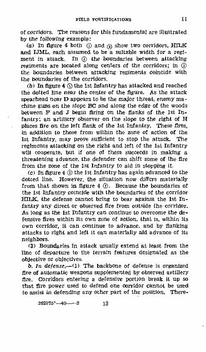
(a) In figure 4 both (D and ( show two corridors, HILKand IJML, each assumed to be a suitable width for a regi-ment in attack. In ( the boundaries between attackingregiments are located along centers of the corridors; in othe boundaries between attacking regiments coincide withthe boundaries of the corridors.
(b) In figure 4 @ the ist Infantry has attacked and reachedthe dotted line near the center of the figure. As the attackspearhead near D appears to be the major threat, enemy ma-chine guns on the slope BC and along the edge of the woodsbetween F and J begin firing on the flanks of the Ist In-fantry: an artillery observer on the slope to the right of Hplaces fire on the left flank of the Ist Infantry. These fires,in addition to those from within the zone of action of theIst Infantry, may prove sufficient to stop the attack. Theregiments attacking on the right and left of the ist Infantrywill cooperate, but if one of them succeeds in making athreatening advance, the defender can shift some of the firefrom the zone of the Ist Infantry to aid in stopping it.
(c) In figure 4 ® the Ist Infantry has again advanced to thedotted line. However, the situation now differs materiallyfrom that shown in figure 4 (D. Because the boundaries ofthe Ist Infantry coincide with the boundaries of the corridorHILK, the defense cannot bring to bear against the Ist In-fantry any direct or observed fire from outside the corridor.As long as the Ist Infantry can continue to overcome the de-fensive fires within its own zone of action, that is, within itsown corridor, it can continue to advance, and by flankingattacks to right and left it can materially aid advance of itsneighbors.
(3) Boundaries in attack usually extend at least from theline of departure to the terrain features designated as theobjective or objectives.
b. In defense.--() The backbone of defense is organizedfire of automatic weapons supplemented by observed artilleryfire. Corridors entering a defensive portion break it up sothat fire power used to defend one corridor cannot be usedto assist in defending any other part of the position. There-
262375 °140-2
11
13

ENGINEER FIELD MANAIUA
fore the defender seeks a positionf without corridors becausethey weaken his defense by decreasing flexibility of his fire.
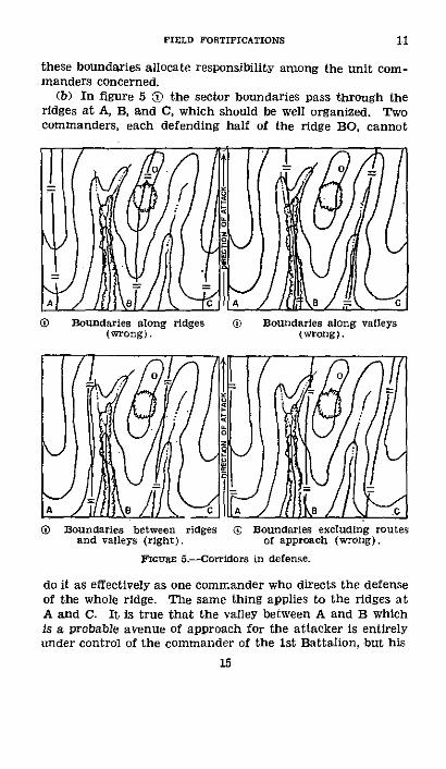
(2) In general, from the standpoint of the most advan-tageous use of terrain, boundaries between units in defenseshould neither follow the edges of corridors nor the lines ofprobable enemy approach, but should be situated somewherebetween the two in such a manner as to secure unity of com-mand along the most dangerous avenue of approach. Thereasons for this are illustrated by the following example:- (a) Figure 5 (),O , and (, shows three different methodsof assigning boundaries, the terrain being the same in allfigures, Figure 5 (D shows sector boundaries coinciding with
~A S L AS E&
( Boundaries in centers of cor- ® Boundaries at edges of cor-ridors (wrong). ridors (right).
FGrmr 4.-Corridors in attack,
boundaries of corridors as is proper in attack. Figure 5 O'shows sector boundaries following lines of probable enemyapproach within the corridors. Figure 5 (O shows sectorboundaries placed between those shown in (D and (6. Ineach case it is assumed that the boundaries mark off frontageswhich can be defended by an infantry battalion. Properdefense of the area requires that the ridges through A, B,and C be organized for strong all around defense; the valleysbetween the ridges being defended by flanking fire fromthe ridges and by frontal fire from the rear portions of theposition. Location of sector boundaries is important because
14
11
FIELD FORTIFICATIONS
these boundaries allocate responsibility among the unit com-manders concerned.
(b) In figure 5 (D the sector boundaries pass through theridges at A, B, and C, which should be well organized. Twocommanders, each defending half of the ridge BO, cannot
0 Boundaries along ridges (D Boundaries along valleys(wrong). (wrong).
LA0
/ 11tl \8 /1. 911 A / ItIIkA / /I / / \ -.Boundaries between ridges X Boundaries excluding routes
and valleys (right), of approach (wrong).FIGURE 5.-Corridors in defense.
do it as effectively as one commander who directs the defenseof the whole ridge. The same thing applies to the ridges atA and C. It is true that the valley between A and B whichis a probable avenue of approach for the attacker is entirelyunder control of the commander of the 1st Battalion, but his
15
t11
11 ENGINEER FIELD MANUAL
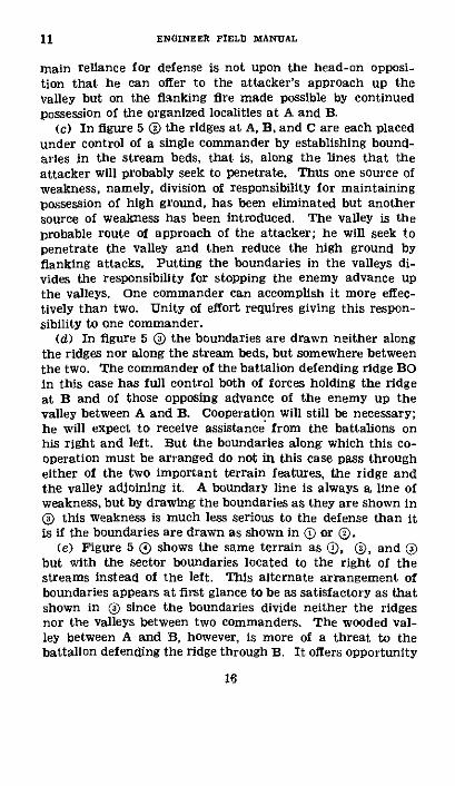
main reliance for defense is not upon the head-on opposi-tion that he can offer to the attacker's approach up thevalley but on the flanking fire made possible by continuedpossession of the organized localities at A and B.
(c) In figure 5 () the ridges at A, B, and C are each placedunder control of a single commander by establishing bound-aries in the stream beds, that is, along the lines that theattacker will probably seek to penetrate. Thus one source ofweakness, namely, division of responsibility for maintainingpossession of high ground, has been eliminated but anothersource of weakness has been introduced. The valley is theprobable route of approach of the attacker; he will seek topenetrate the valley and then reduce the high ground byflanking attacks. Putting the boundaries in the valleys di-vides the responsibility for stopping the enemy advance upthe valleys. One commander can accomplish it more effec-tively than two. Unity of effort requires giving this respon-sibility to one commander.
(d) In figure 5 () the boundaries are drawn neither alongthe ridges nor along the stream beds, but somewhere betweenthe two. The commander of the battalion defending ridge BOin this case has full control both of forces holding the ridgeat B and of those opposing advance of the enemy up thevalley between A and B. Cooperation will still be necessary:he will expect to receive assistance from the battalions onhis right and left. But the boundaries along which this co-operation must be arranged do not in this case pass througheither of the two important terrain features, the ridge andthe valley adjoining it. A boundary line is always a line ofweakness, but by drawing the boundaries as they are shown ino this weakness is much less serious to the defense than itis if the boundaries are drawn as shown in (i or 0(.
(e) Figure 5 0( shows the same terrain as (D, (D, and (but with the sector boundaries located to the right of thestreams instead of the left. This alternate arrangement ofboundaries appears at first glance to be as satisfactory as thatshown in (3 since the boundaries divide neither the ridgesnor the valleys between two commanders. The wooded val-ley between A and B, however, is more of a threat to thebattalion defending the ridge through B. It offers opportunity
16

FIELD FORTIFICATIONS
for an attacker to advance up the Valley by using the woodsfor cover, capture the woods on the top of the ridge near 0,and then capture the entire ridge from 0 to B by attackingdownhill from the rear. The commander of the battaliondefending BO therefore has the greater interest in defense ofthis approach, and its defense should consequently be as-signed to him by drawing the boundaries as they are shownin ( rather than as shown in (.
(3) The preceding considerations apply particularly tothose portions of the boundaries within the position and at theshorter ranges to the front. It may be found that their con-tinuation to the front at the longer infantry ranges involvesuse of terrain differing from that in the close-in defense. Forexample, in figure 6 the boundary AB is properly located forclose-in defense. In extending this boundary to the front inorder to place responsibility for longer range fire it would.following the same considerations that led to establishmentof boundary AB, extend forward through F, G, and H. Thenenemy machine guns at X and Y are in the sector of the 2dInfantry and should be covered by the fire of that unit. How-ever, the defilade provided by the ridge CDE prevents the 2dInfantry from firing on X and Y, and also prevents guns at Xand Y from firing into the sector of the 2d Infantry. Theguns at X and Y can fire into the sector of the 1st Infantry,and can be covered by fire from the Ist Infantry. If theboundary is shifted to CDE instead of FGH, responsibility fortaking care of these machine guns is placed where it belongs,namely, on the ist Infantry. The ridge CDE is utilized prop-erly from the standpoint of terrain when the boundary linebetween the Ist Infantry and 2d Infantry is drawn along thetop of the ridge, thus giving to the Ist Infantry the east slopein which it has a paramount interest, and to the 2d Infantrythe west slope in which it has a paramount interest.
(4) The same considerations apply when boundaries ofterrain compartments are formed by villages or woods insteadof by ridges. In figure 7 the village and woods are importantfeatures of the terrain. Responsibility for their defenseshould therefore not be divided as it is in ( but should beplaced under a single commander as shown in C(). (An at-
17
11

ENGINEER FIELD MANUAL
tacker would locate his boundaries as shown in (DQ, that is,along edges of the corridor formed by the village and woods.)
c. Extension of boundaries.-At longer ranges to the front,boundaries are intended primarily to coordinate artillery firesand will be influenced by location of possible hostile assemblyareas and routes of approach. Such boundaries extending
Z
fouGs 6.--Extension of boundaries.
sectors to the limits of artillery fire in front of defensive posi-tions frequently are placed along the crests of ridges. Theextension of boundaries to the rear in both attack and de-fense is influenced largely by the location of routes of com-munication essential to supply and movement within thesector.
18
-PROBABLE DIRECTION
lm < ..
11
OF ATTACK--

FIELD FORTIFICATIONS 11
CD Wrong. ( Right.
FIrone 7.-Corridors between woods and villages in defense.
FloGu 8.-Cross compartment.
19
IC
4ti
0
-
I

ENGINEER FIELD MANUAL
U 12. INFLUENCE OF CROSS COMPARTMENTS.---. On defense-In figure 8 the ridge AB is one bourdary of cross compart-ment ABDC. The observation available to the defender fromthis boundary is very valuable; consequently he should disposehis forces well to the front of it in order that local successesby the attacker may not result in loss of so valuable anasset. The cross compartment as a whole is a valuable assetto defense because mutually supporting fires can be organ-ized across its entire length from AC to BD. Until the de-fender is actually driven from the line AB he retains hisobservation over the entire area. In general therefore across compartment favors the defense and handicaps theattack.
b. On attack.--Boundaries of cross compartments formnatural objectives for attack or limited objectives along theline of attack. Until the entire area ABDC has been cap-tured and the defender driven beyond the ridge AB, theattack or at any rate this particular phase is not complete.When the ridge has been taken the attacker may have. abreathing spell in which to reorganize his forces, move hisobservers forward to points from which they can see intothe adjoining cross compartment, and make his plans forthe next phase of the attack which will be capture of thenext cross compartment in its entirety.
c. Unit boundaries.-From a terrain standpoint, the bound-aries between attacking units may be located with equaleffect anywhere between AC and BD. There will of coursebe other factors such as knownr disposition of defendingforces that will influence location of boundaries betweenattacking units, but the terrain is so uniform over this par-ticular area that its influence on boundaries is negligible.The boundaries between sectors in the defense can also beplaced anywhere, as unit commanders can cooperate alongone line just as well as along another. In other words, thereare no terrain features that limit lateral visibility so locationof boundaries between units would be determined by factorsother than terrain.* 13. AIDS TO STUDY OP TERRAIiN.-a. Drainage lines andridge lines form the natural basis for the study of terrainwith respect to shape of the ground. When such study of
20
12-13

FIELD FORTIFICATIONS
ground forms is made on a map or aerial photograph it canbe aided materially by-
(1) Emphasizing drainage lines by marking heavily (fig.9@).
(2) Drawing in heavy lines along crests of ridges, called"ridge-lining" (fig. 9 0 ).
(3) (On contoured maps.) Emphasizing certain contourswith heavy lines (fig. 9 ()) or coloring map areas betweencontours with different colors to make ground forms and com-manding elevations more apparent. (See TM 5-220.)
b. Drainage lines always form a connected system or sys-tems of branching lines. Ridge lines form similar systemsof branching lines since spurs and the smaller ridges branchoff from large main ridges just as small streams and gulliesbranch off from the main streams. Drainage lines and ridgelines thus form two interlocking, branching systems whicheither singly or together indicate clearly the general shape ofthe ground. When both systems are emphasized on a map orphoto, different colors should be used, preferably blue fordrainage lines and brown for ridge lines to conform to usualmap colors. The more important ridge or drainage lines maybe given special emphasis by drawing them in heavier lines.
c. It will occur frequently that ridge lines and drainagesystems are not the only terrain features of outstanding im-portance in a tactical situation. There may be forests, towns,railroads, etc., to which particular attention must be paid.In such cases these features may be emphasized in muchthe same ways as described above for ridge lines and drainagesystems.
d. Further details regarding tactical study of terrain, to-gether with a form therefor, are given in FM 101-5.
SECTION m
ORGANIZATION OF THE GROUND
* 14. GENnRAL.--a. Organization of the ground is the devel-opment of a defensive position to its full strength by-
(1) Providing fields of fire for all flat trajectory infantryweapons.
21
13-14

ENGINEER FIELD MANUAL
O Emphasizing drainage.
( Ridge-lining.
® Emphasizing contours.FIomE 9.-Map aids to terrain studies.
22
14
FIELD FORTIFICATIONS
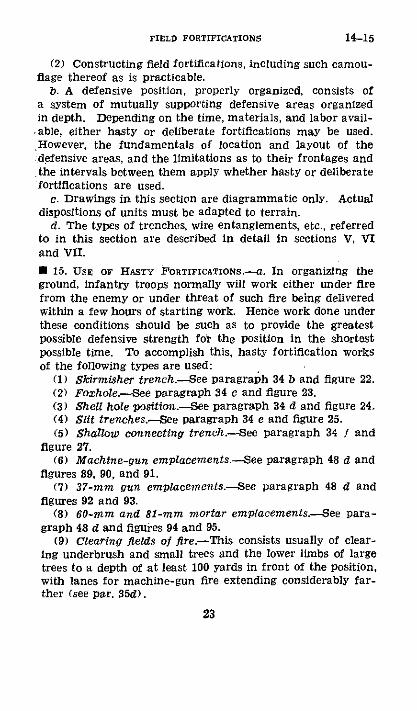
(2) Constructing field fortifications, including such camou-flage thereof as is practicable.
b. A defensive position, properly organized, consists ofa system of mutually supporting defensive areas organizedin depth. Depending on the time, materials, and labor avail-,able, either hasty or deliberate fortifications may be used.However, the fundamentals of location and layout of thedefensive areas, and the limitations as to their frontages andthe intervals between them apply whether hasty or deliberatefortifications are used.
c. Drawings in this section are diagrammatic only. Actualdispositions of units must be adapted to terrain.
d. The types of trenches, wire entanglements, etc., referredto in this section are described in detail in sections V, VIand VII.
· 15. USE OF HASTY FORTIFICATIONS.-a. In organizing theground, infantry troops normally will work either under firefrom the enemy or under threat of such fire being deliveredwithin a few hours of starting work. Hence work done underthese conditions should be such as to provide the greatestpossible defensive strength for the position in the shortestpossible time. To accomplish this, hasty fortification worksof the following types are used:
(1) Skirmisher trench.-See paragraph 34 b and figure 22.(2) Foxhole.-See paragraph 34 c and figure 23.(3) Shell hole position.-See paragraph 34 d and figure 24.(4) Slit trenches.-See paragraph 34 e and figure 25.(5) Shallow connecting trench.-See paragraph 34 f and
figure 27.(6) Machine-gun emplacements.-See paragraph 48 d and
figures 89, 90, and 91.(7) 37-mm gun emplacements.-See paragraph 48 d and
figures 92 and 93.(8) 60-mm and 81-mm mortar emplacements.-See para-
graph 48 d and figures 94 and 95.(9) Clearing fields of fRre.-This consists usually of clear-
ing underbrush and small trees and the lower limbs of largetrees to a depth of at least 100 yards in front of the position,with lanes for machine-gun fire extending considerably far-ther (see par. 35d).
23
14-15

15 ENGINEER PIELD MANUAL
(10) Obstacles.-Barbed wire entanglements form themajor obstacles against foot troops. The double-apron fence(see par. 42c (4) and figs. 75 and 76) is the most efficienttype, but where time is short or materials lacking, the four-strand fence (see par. 42c (6) and fig. 80) may be used.Provision of antitank obstacles will ordinarily be limited toimprovement of natural obstacles as streams, ditches, etc.,'and laying antitank mine fields.
(11) CamoulJage.-Camouflage to be effective must beexecuted simultaneously with the defensive works. Spoilshould be properly disposed of as soon as dug; parapetsshould be sodded as fast as they are finished; emplacements
A Tem ATe R RTea R Toamr
SIt $ ud .squad
-'a> BAR Squad ---- quad leader 5leaderquad leader sii L eont BAR quadL-A~~SS;t leaer ! Se squad leader leader
O P, plato" 0 P seMdqrleader
FicuRE 10.--Rifle platoon in fox holes with connecting trenches(12-man squads).
should be concealed under fishnets or natural materials fromthe start, and paths pointing to defensive works should beavoided (see FM 5-20).
b. Clearing fields of fire is of first priority; however, inmost instances a small detail can complete the clearingwhile some of the men dig fox holes, others prepare emplace-ments, etc. It usually will be advisable to start placing obsta-cles early in the work. Thus an enemy attack will encountera fairly well-organized position. As more time becomes avail-able, the initial hasty fortifications are gradually developed
24

FIELD FORTIFICATIONS
into deliberate fortifications. Fox holes and shallow connect-ing trenches are converted into standard fire and communi-cation trenches; open emplacements are changed to coveredtypes; existing obstacles are strengthened and new obstaclesadded; protected shelters for personnel are provided, etc.
U 16. USE OF DELIBERATE FORTIFICATIONS.-a. In the case ofdefensive positions organized in rear areas out of contactwith the enemy, the fortifications constructed normally willbe' of the deliberate type with no attempt being made firstto provide hasty fortifications and then develop these intodeliberate fdrtifications. The initial work will consist atleast of standard fire trenches, open-standing or splinterproofweapon emplacements, complete double-apron entanglements,adequate antitank obstacles, and clearing extensive fieldsof fire.
b. Description of various defensive areas given in the fol-lowing paragraphs is based on use of deliberate fortificationsin a rear position. The work indicated is the minimum con-sistent with an adequate defense. These descriptions maybe applied to defensive areas utilizing hasty fortifications byallowing for the fact that fox holes will be used in place offire trenches, that the belts of obstacles will be comparativelyincomplete, and that weapon emplacements will all be ofthe open shallow or standing types.
i 17. BATTLE POSITION.-a. Definition.-In defense of a posi-tion, troops are distributed along the front within a zonewhich is called the battle position. This is the position ofprincipal resistance in defense consisting of a system ofmutually supporting defensive sectors and areas disposed inbreadth and depth. Each sector and area has a definiteassignment of troops and a definite mission.
b. Organization.-(1) Depth.-A battle position should beorganized in depth for two reasons:
(a) A single line of defense could be penetrated easily andthe attacker would then be able to destroy vital installationsin rear on which defending troops depend in order to fight.Instead of a single line the defense must present a seriesof resisting areas which the attacker will have to penetratesuccessively with increasing resistance before he can reachthese installations.
25
15-17
ENGINEER FIELD MANUAL
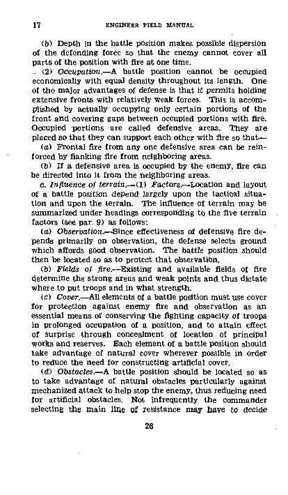
(b) Depth in the battle position makes possible dispersionof the defending force so that the enemy cannot cover allparts of the position with fire at one time.. (2) Occupation.-A battle position cannot be occupied
economically with equal density throughout its length. Oneof the major advantages of defense is that it permits holdingextensive fronts with relatively weak forces. This is accoim-plished by actually occupying only certain portions of thefront and covering gaps between occupied portions with fire.Occupied -portions are called defensive areas. They areplaced so that they can support each other with fire so that-
(a) Frontal fire from any one defensive area can be rein-forced by flanking fire from neighboring areas.
(b) If a defensive area is occupied by the enemy, fire canbe directed into it from the neighboring areas.
c. Influence of terrain.-(l) Factors.-Location and layoutof a battle position depend largely upon the tactical situa-tion and upon the terrain. The influence of terrain may besummarized under headings corresponding to the five terrainfactors (see par. 9) as follows:
(a) Observation.--Since effectiveness of defensive fire de-pends primarily on observation, the defense selects groundwhich affords good observation. The battle position shouldthen be located so as to protect that observation.
(b) Fields of fire.--Existing and available fields of firedetermine the strong areas and weak points and thus dictatewhere to put troops and in what strength.
(c) Cover.-All elements of a battle position must use coverfor protection against enemy fire and observation as anessential means of conserving the fighting capacity of troopsin prolonged occupation of a position, and to attain effectof surprise through concealment of location of principalworks and reserves. Each element of a battle position shouldtake advantage of natural cover wherever possible in orderto reduce the need for constructing artificial cover.
(d) Obstacles.-A battle position should be located so asto take advantage of natural obstacles particularly againstmechanized attack to help stop the enemy, thus reducing needfor artificial obstacles, Not infrequently the commanderselecting the main line of resistance may have to decide
26
17

FIELD FORTIFICATIONS
whether a natural obstacle or observation is the most im-portant consideration.
(e) Routes of communication.-A battle position should belocated so as to use existing roads, railroads, and other routesof communication as far as possible to meet its supply andevacuation requirements, and thus reduce need for new con-struction.
(2) Critical features.-Whether it is a point affording com-manding observation or whether some other element of ter-rain, there may be some terrain feature whose possession byus or denial to the enemy will result directly or indirectly inaccomplishment of an important step in the plan of opera-tions. Such a feature is termed a critical point. For ex-ample, a critical point may be a feature which is especiallyimportant for subsequent parts of the maneuver, or it maybe a sensitive point the capture of which by the enemy maylead to breaking up our whole defense.
(3) Features vital to success of mission.-If a critical pointis of such outstanding importance that its possession by usor denial to the enemy will result in accomplishment of themission or its loss in failure of the mission, then it may besaid to be vital or essential to success of the mission. Such atactical locality is termed a key point, The importance ofsuch a feature may result from its having been named in themission or in orders, or the importance may be deduced from astudy of the terrain. On the other hand, there may be nosuch feature. When there is such, it is frequently a logicalobjective of the enemy's main attack either directly or byoutflanking, or it may be the terrain feature which is theobject of the main effort of the defense.
d. Composition.-A battle position is subdivided into de-fensive areas in such a way as to conform to subdivision ofthe defending force into tactical units. This permits eachdefensive area to be occupied by a single tactical unit ofappropriate size, and provides for unified control of groupsof defensive areas through the normal chain of command(see fig. 11).
(1) The platoon defense area is usually the smallest de-fensive area. The company defense area, the next largestdefensive area, is a group of platoon or smaller defense areas
27
17

ENGINEER FIELD MANUAL
under control of the company. A battalion defense area is adefensive area composed of a group of company defense areasunder control of the battalion commander. A regimentaldefensive area is a group of battalion defense areas underregimental control, and is called a regimental sector.
(2) A line at the forward boundary of the battle positiondesignated to coordinate the defensive fires of all units andsupporting weapons is called the main line of resistance(MLR) (see fig. 11). In rear of company defense areas
rGuItE 11.-Composition of battle position.
on or near the main line of resistance may be companydefense areas forming battalion reserves. A line designatedto coordinate the locations and actions of the regimentalreserves in the battle position is term the regimental reserveline (RRL).
(3) The defense areas assigned units in defense will varywith mission of the command, natural defensive strengthof the ground, importance of the sector to the defense as a
28
17

FIELD FORTIFICATIONS 17-18
whole, degree of control required, and number and strengthof units available for the whole defense.
* 18. PLATOON DEFENSE AREA.-a. A platoon defense area isorganized for all around defense. It may consist of one firetrench for each squad in the area and a belt of obstacles,usually wire entanglements, entirely surrounding the area.It is not normally organized in depth, the squad trenchesbeing roughly in line rather than one in rear of the other(see fig. 12).
b. The frontage which can be defended depends on manyfactors including mission, size of the unit assigned thereto,and terrain. See Table I which is furnished as a generalguide only.
TABLE .--Frontage (in yards)
Minimum (heavily woodedterrain)
Sire of unit defenseareas Interal Total
beteena actually frontdefese occupied defended
1 quad (12 meo)_ 25 30 55Platoon, less 1
squad (2squads) .. 50 75 125Full platoon (3
squads) 100 100 200
Intbetdela'
Maxrimum (fiat, openterrain)
erval n Frontage Totalense actually frontcas occupied defended
100 50 150
150 100 250
200 200 4(0
c. Each defense area should be able to cover by fire its ownfront, the fronts of adjacent defense areas, and the unoccu-pied intervals between them. Hence, squad trenches on theflanks of a platoon defense area may be faced partly towardadjacent areas to facilitate such flanking fire. Each squadtrench should provide at least 5 lineal feet per man. Thesimple standing fire trench, preferably with the octagonaltrace, represents minimum protection to be provided bysquad trenches when time and conditions permit.
d. The purpose of the belt of obstacles surrounding aplatoon defense area is to prevent the trenches being rushedor surprised by foot troops. Such an obstacle must be close
292623751--0 -3

18-19 ENGINEER FIELD MANUAL
enough to the trenches to be under observation and fireat all times, especially at night, but must not be so closeas to permit an enemy to approach within hand grenaderange of the trenches. A distance of from 30 to 100 yardsfrom the trenches generally will be suitable. The obstaclesshould at a minimum consist of the four-strand fence orits equivalent. When the interval between defensive areas issmall the obstacles on the flanks will be less than 30 yardsdistant from the trenches. Obstacles should be concealedso that the enemy is surprised by them.
e. Squad trenches should be provided with clear fields offire throughout the width of their assigned sectors at leastas far forward as the belt of obstacles and preferably to agreater distance.0 19. COMPANY DEFENSE AREA.-a. The platoon defense areasof a company defense area are located with a view to resist-ance to the front and flanks and if necessary to the rear. Acompany defense is normally organized for a protracted allaround defense.
b. A company can defend a front of from 400 to 600 yards,depending on terrain. The portion of this front which isactually occupied is generally not less than 200 yards inwidth by 100 yards in depth in order to minimize losses fromenemy fire, and not greater than 400 yards in width by 300yards in depth in order to avoid undue dispersion.
c. Supporting weapons.-(1) Light machine guns areplaced within platoon defense areas in accordance with thebattalion plan of fire (see par. 20 e.) The guns may be sitedindividually for employment on separate missions. Theyshould be provided with open standing type emplacementscarefully concealed, with alternate emplacement for eachgun from which its primary fire mission can be accomplished.
(2) The 60-mm mortars may be located in a single groupwithin a company defense area far enough forward to haveobserved fire and at a point where they have natural defiladefrom the front, or they may be placed in platoon defenseareas in accordance with the battalion plan of fire. Whereno natural defilade exists, they should be put in open em-placements and provided with an approach trench for am-munition supply. In any case they should be concealed. It
30
FIELD FORTIFICATIONS 19-20
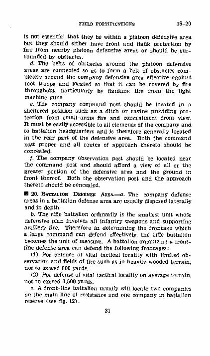
is not essential that they be within a platoon defensive areabut they should either have front and flank protection byfire from nearby platoon defensive areas or should be sur-rounded by obstacles.
d. The belts of obstacles around the platoon defensiveareas are connected so as to form a belt of obstacles com-pletely around the company defensive area effective againstfoot troops and located so that it can be covered by firethroughout, particularly by flanking fire from the lightmachine guns.
e. The company command post should be located in asheltered position such as a ditch or ravine providing pro-tection from small-arms fire and concealment from view.It must be easily accessible to all elements of the company andto battalion headquarters and is therefore generally locatedin the rear part of the defensive area. Both the commandpost proper and all routes of approach thereto should beconcealed.
f. The company observation post should be located nearthe command post and should afford a view of all or thegreater portion of the defensive area and the ground infront thereof. Both the observation post and the approachthereto should be concealed.
U 20. BATTALION DEFENSE AREA.-. The company defenseareas in a battalion defense area are usually disposed laterallyand in depth.
b. The rifle battalion ordinarily is the smallest unit whosedefensive plan involves all infantry weapons and supportingartillery fire. Therefore in determining the frontage whicha large command can defend effectively, the rifle battalionbecomes the unit of measure. A battalion organizing a front-line defense area can defend the following frontages:
(1) For defense of vital tactical locality with limited ob-servation and fields of fire such as in heavily wooded terrain,not to exceed 800 yards.
(2) Por defense of vital tactical locality on average terrain,not to exceed 1,500 yards.
c. A front-line battalion usually will locate two companieson the main line of resistance and one company in battalionreserve (see fig. 12).
31

ENGINEER FIELD MANUAL
(1) Companies on the main line of resistance organizecompany defense areas capable of mutual support.
(2) The function of the battalion reserve is to expel theenemy by fire and movement from any portion of the bat-talion area which may have been occupied by the enemy.Should the tactical situation prevent counterattack, the re-serve must stop or delay further advance of the enemy andmust accordingly be prepared for defense to the front, flanks,and rear.
d. A battalion defense area on the regimental reserve lineordinarily must cover the combined frontages of two battalionareas on the main line of resistance. A battalion in regi-mental reserve usually prepares positions for its companiesabreast along the regimental reserve line: any organizationin depth of the regimental reserve position must be accom-plished by the companies in their dispositions of rifle platoons,light machine guns, and 60-mm mortars.
e. Supporting weapons.-A battalion plan is drawn up foruse of all supporting weapons.
(1) Heavy machine guns.-(a) The heavy machine gunsare disposed in width and depth throughout the battaliondefense area. Their fire forms the framework with which allother fire directed against foot troops is coordinated, otherweapons being used to fill in any gaps in such fire. Theyshould be able to cover the front of the position with con-tinuous interlocking bands of grazing fire, and to cover themost likely avenues of enemy approach with enfilading fire.Other weapons are used to fill in any gaps in fire of machineguns. The primary mission for each gun normally includesplacing an extended band of grazing fire along the wire orother obstacle on the front or flank of a defensive area, suchfire to be delivered under any conditions of visibility. The linealong which this fire is delivered is called the final protectiveline.
(b) It is necessary to provide depth to machine-gun de-fense so that the guns will be in position both to preventenemy penetration to the rear part of the position and tosupport counterattacks.
(c) Heavy machine guns are sited in pairs, the guns ofeach pair having identical sectors of fire. They are located
32
20

FIELD FORTIFICATIONS
either within or under protection of platoon defense areas.Each gun should have primary and alternate emplacementsfrom which their primary mission can be accomplished, anda supplementary emplacement from which a secondary mis-sion can be accomplished. The guns in a pair should bespaced 20 to 50 yards apart, close enough for control byone man but far enough apart so that one shell burst can-not put both guns out of action. Primary and alternateemplacements should be at least 50 yards apart so that firedirected on one location will not through natural dispersioncover both. All emplacements should provide splinterproofshelter and should have covered routes of approach orapproach trenches for supply and communication.
(2) Mortars.-The 81-mm mortars are assigned a posi-tion area within the battalion defense area far enough tothe rear of the main line of resistance so that they candirect fire into platoon defense areas on that line withoutdisplacing to the rear. Within the position area each mor-tar is provided with primary and alternate emplacementsso located that from them fire can be directed on any gapsin fire of the flat trajectory weapons. Each mortar requiresan observation post and a covered route of approach. Allemplacements should be the open standing type carefullyconcealed from air and ground observation. They shouldpreferably be located in defiladed positions.
(3) Antitank guns.-The mission of the battalion anti-tank guns is to provide protection for the battalion sectorfrom tank attacks. The guns should therefore be located soas to cover probable routes of approach for tanks. Theyshould be far enough forward to engage a tank attack be-fore it reaches the main line of resistance, but in any caseshould not be forward of the front line of platoon defenseareas. The guns are distributed laterally rather than indepth, and where possible should be able to fire in supportof each other. They should be provided with primary, alter-nate, and supplementary positions, all of the open stand-ing type, well concealed. As the guns operate by directobserved fire only, all emplacements must be located andconstructed to permit this.
33
20

ENGINEER FIELD MANUAL
f. A battalion defense area is organized for all arounddefense against both foot troops and tanks.
(1) Belts of obstacles surrounding the company defenseareas are connected so as to form a continuous belt effectiveagainst foot troops around the battalion defense area locatedso that all points can be covered by fire. Particular atten-tion must be paid to siting of obstacles so they can beenfiladed by fire of heavy machine guns. Wire entangle-ment placed primarily for this purpose is called tacticalwire, as distinguished from wire entanglement used primarilyto protect a platoon defense area from being rushed, whichis called protective wire. Wherever possible, both functionsshould be performed by one belt of wire or other obstacle inorder to conserve materials and labor.
(2) Tank obstacles should be provided to block all possibleavenues of approach for tanks into the battalion defense area.Locations of tank obstacles and battalion antitank guns shouldbe coordinated so that the guns can cover the obstacles by fire,if possible. Otherwise the antitank guns are located to coverthe most favorable approaches for tanks not covered byobstacles.
g. Battalion command and observation posts are located inaccordance with provisions enunciated for the company, thecommand post usually being in the battalion reserve area.
h. Company and platoon defense areas should be assignedsectors or positions which will most effectively protect the keypoint of the battalion defense area by covering routes of ap-proach to the key point with planned fire. Development ofthe fire plan involves siting weapons and assignment of sectorsand areas of fire so that all area in front of the position can becovered by some type of destructive fire, and that fire can bedelivered against the enemy if and when he succeeds in pene-trating any part of the position. It is essential to coordinatefire of subordinate units to avoid and eliminate duplication, toassure that all areas are covered, to see that fire gives mutualprotection to adjacent units and weapons, to assure maximumdevelopment of flanking fires, and to see that fires arecapable of being switched and shifted to meet unexpecteddevelopments.
34
20

FIELD FORTIFICATIONS
* 21. REGIMENTAL SEcTORS.--. A regimental sector is the larg-est defensive area in a battle position and is the only one whichcompletely covers the battle position in depth. It normallyconsists of three battalion defense areas, of which two are onthe main line of resistance and one on the regimental reserveline. They are disposed so as to occupy and defend keypoints
FICuE 12.-Battallon defense area.NoTr.-Locations and fires of all weapons of the battalion to in-
clude light machine guns of rifle companies and locations of their60-mm mortars are shown. Primary target areas for the 81-mmmortars and normal barrages of supporting artillery are shownNote that some of the 60-mm mortars are attached to front-lineplatoons and that the caliber .30 light machine guns are employedin the defense in the same manner as heavy cal. .30 machine guns.
within the regimental sector, and so as to protect keypoints inrear of the regimental sector, especially those affording obser-vation to the supporting artillery. Their fire must be coordi-nated both within the regimental sector and with that ofadjoining sectors.
35
21

21-23 ENGINEER FIELD MANUAL
b. 37-mm antitank guns.-(1) Antitank defense of a regi-mental sector consists of two coordinated echelons, the bat-talion antitank guns for defense of forward areas and the regi-mental 37-mm antitank guns to give depth to the defense andto protect the flanks. They should either be placed within orunder protection of company defense areas or be assignedtroops to furnish local protection.
(2) Due to its low mount, the antitank gun cannot be dugin at its firing position. When not in action the guns areusually held in positions of readiness near their firing posi-tions in areas defiladed from flat trajectory fire, shelter orconcealment being provided for gun and crew. Firing posi-tions should be located on commanding ground with wide,clear sectors of fire covering probable routes of tank approach.They are not prepared except for providing fox holes for oper-ating crew and digging in ammunition.
c. In organizing the regimental sector, no obstacles againstfoot troops are ordinarily provided beyond those included inthe battalion defense area. However, additional antitank ob-stacles normally will be necessary. They usually will includethe more readily constructed types such as mine fields andheavy abatis. Their location should be coordinated with fireof antitank guns and caliber .50 machine guns so that all suchobstacles are covered by fire.
d. Antiaircraft protection within the regimental sector islimited to prescribing areas of air responsibility for the vari-ous subordinate units and assigning antiaircraft fire missionsas primary missions to certain units or weapons, principallyto heavy machine guns.
* 22. ADDITIONAL ORGANIZATION-The preceding paragraphsdo not describe a complete organization of the ground;rather, they indicate the minimum that should be done for arear position. The defensive strength of a position can beincreased materially by connecting squad trenches, provid-ing approach trenches, strengthening tank obstacles, pro-viding shellproof weapon emplacements and protected shel-ters for personnel, and such other additional work as thesituation demands or time and labor permit.
* 23. ARTILLERY SUPPORT.-In addition to organic weapons.the infantry normally receives direct support from artillery
36

FIELD FORTIFICATIONS 23-24
in the form of barrages and concentrations covering suchareas and delivered at such times as the Infantry desires.Pertinent data on such fire are given in table II.
TABLE II.-Placing of barrage fired by a battery of fieldartillery
hIinimum safe dist-Area of barrage Dim anc from in-
Call- Burst eter of fantry in-ber TyPO 1 teron-
(mm) she'aslllNormal Eer- traio pen Trenches
75 G --un--. S--l x 3O 100 x 200 100x 30 100-300 200500 200-400
105 Bow - . 9x 40 100 x 300 1x 40 200-400 300-40 200-400
155 ow 90 200-40 600-700 300-400n ........fow
Non.--All dimensions given are in yards. Safe distances will varywith ranges and nature and efficiency of observation. In general,barrages should be placed at distances of 300-500 yards from infan-try. If protection furnished is exceptionally good, minimum dis-tances given may be reduced by about 50 yards.
* 24. OTrposT AREA-a. The enemy situation permitting,every battle position should.be covered by an outpost to thefront. The area in front of the main line of resistance ofthe battle position occupied by the outpost is called theoutpost area.
b. When the outpost troops have only the usual outpostmissions, that is, to protect troops in rear against surprise,to prevent an attack upon them before they can be preparedto resist, and to prevent or restrict enemy reconnaissance andground observation, little effective resistance to a generalattack is expected. The outpost consists of squads, platoons,companies, or battalions, depending on depth of the outpostarea, sent forward by units holding the battle position. Littleground organization is contemplated. An outpost line ofresistance (OPLR) should be designated along which theoutpost is disposed so as to carry out its mission. The firesof elements of the outpost and its supporting artillery arecoordinated along this line.
37

ENGINEER FIELD MANUAL
c. When in addition to the above missions the outpost ischarged with absorbing shock of an attack, depriving it ofmomentum and breaking up the enemy organization, battleensues over a zone of considerable depth. The outpost areais organized as thoroughly as conditions will permit, andbattle positions and organized outpost area collectively arecalled a defensive zone (see fig. 13).
eft, I.
x Oca/ Secanty
L-. -Mai_ n line ores'rnce- ,1._ rnnezed 0
-_ Pty Rgirrien eserve Lttc- ___.… iPsiton >
Arlill cry Xi
and I idI C~~
PIGurE 13.--efensive zone (square division).
38
24

FIELD FORTIFICATIONS
d. Organization of the outpost area is coordinated by des-ignation of a line of resistance for the outpost which shouldbe located not less than 1,500 nor more than 4,000 yards infront of the main line of resistance in order to give sufficientdepth to the outpost area and in order that artillery locatedbehind the battle position can support the outpost and placefire from 1,500 to 2,000 yards beyond the front line. A lineof observation is established in front of the outpost line ofresistance. Outpost forces generally consist of battalions orcompanies with attached machine guns sent forward by regi-ments or brigades holding sectors of the defensive zone. Theorganization consists of mutually supporting tactical locali-ties similar to those heretofore described for the battle posi-tion. Units of the outpost usually are required to covermore extensive fronts than similar units on the battle position.This results in greater intervals between tactical localities.Companies may be required to cover 800 to 1,500 yards offront and a battalion 2,000 to 2,500 yards. The importanttactical localities in an outpost area are those which furnishimportant observation into the enemy territory and controlprobable routes of enemy advance into the defensive system.These are organized usually as company defense areas orif their importance warrants as battalion defense areas.Intervals between these important localities should not exceed3,000 Yards. Where necessary, intervals between these de-fense areas are covered by the organization of detachedplatoon defense areas. Because of the longer time they canhold out and the greater effect of larger organizations inbreaking up enemy attack formations, provision should bemade in case of a general attack for withdrawal of garrisonsof small organized localities into the larger and moreimportant ones.
e. In some situations in zone defense the importance of thefront held and quantity and power of enemy artillery requirethat the main line of resistance be placed far enough in rearof the OPLR to be beyond effective range of the bulk of thehostile guns, 6,000 to 8,000 yards. This depth of outpostarea is too great to permit adequate support of the outpostfrom the battle position, and some troops (infantry and ar-tillery) must then be located between the front line and the
39
24

24 ENGINEER FIELD MANUAL
battle position to support the forward outpost elements andsupplement their action in delaying and disorganizing hostileattacks. Such an outpost area is in effect a delaying area(fig. 14).
Enemy
7 -c:~P ~f1 C .... X 0 tr/es-
to og fR"'JD AREA
A Adevanced1 ArtLlery
velo n of or o tto o o t o t
nf o tion R the … lininon
Local ResaNs
' Division Se'or
FIuarE 14.-Defensive zone with deep outpost area (square division).
f. Continued occupancy of a defensive zone results in de-velopment of organized tactical localities of the outpost areainto a more or less well-organized position consisting of-
(1) A line of observation (the front line) in front of theline of resistance occupied by outguards to provide observa-tion and defense of the foreground.
40
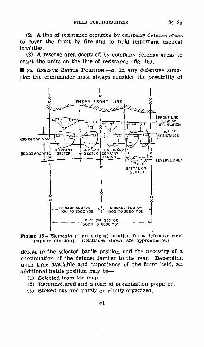
FIELD FORTIFICATIONS
(2) A line of resistance occupied by company defense areasto cover the front by fire and to hold important tacticallocalities.
(3) A reserve area occupied by company defense areas toassist the units on the line of resistance (fig. 15).
* 25. RESERVE BATTLE POSITION.-a. In any defensive situa-tion the commander must always consider the possibility of
I I IENEMY FRONT LINE
·. ~~~ · · ~~~~~FRONT LINELINE OF
OBSERVATION
tio R SISTANCE
CTOOOYDSOPy CTOMPR E TEMPANY \TOFSaoTOR >SECTOR TCOMPrNY,
IGAE SECTTO1500 TO 3000 Y05 1500 TO 3000 YOS.
ODJVSION SECTOR5000 TO 6000 YOS
FIGURE 15,-Elements of an outpost position for a defensive zone(square division). (Distances shown are approximate.)
defeat in the selected battle position and the necessity of acontinuation of the defense farther to the rear. Dependingupon time available and importance of the front held, anadditional battle position may be-
(1) Selected from the map.(2) Reconnoitered and a Plan of organization prepared.(3) Staked out and partly or wholly organized.
41
24-25

ENGINEER FIELD MANUAL
b. Such a position is designated as the "reserve battle posi-tion" (fig. 16). On highly important fronts additional posi-tions in rear of the reserve battle position may be selected,reconnoitered, and staked out. Selection of the reserve battleposition and other positions in rear is based on placing themat such a distance in rear of the battle position next in frontthat the enemy after having successfully attacked a forwardposition would have to advance the bulk of his artillery be-fore undertaking attack of the next battle position. Therequirement calls for a distance of at least 6,000 yards; con-figuration of the terrain may require some modification ofthis rule.* 26. SWITCH POSITIONS.-In addition to the several positionsor organized areas of a defensive zone paralleling the front,additional positions are provided oblique to the front and con-necting the forward position or areas with those in rear.These oblique positions, designated "switch positions" (fig.16), are established on the flanks of localities in the defensivesystem where due to lack of natural defensive strength orfor other reasons there is a probability of an enemy penetra-tion. Attacks against a defensive zone in order to breakthrough the defensive organization on a front broadenough to insure success must be exploited to the flanks asthe advance progresses to counteract narrowing of the initialfront of attack by resistance of the defense. Switch positionsare planned to resist exploitation by the enemy to the flanksof a penetration, to insure continuity of the front whenforward defenses have been broken through, and finally toprovide a line from which general counterattacks against theflank of a penetration may be started.
SECTION IV
EFFECT OF PROJECTILES
I 27. GENERAL.-Penetration and effect of small-arms, ar-tillery projectiles, and aircraft bombs are extremely variable.Fortifications must therefore be designed with large safetyfactors. However, maximum probable penetration and effectmust be kept in mind so that works may be strong enoughto resist projectiles without unnecessary expenditure of laborand material.
42
25-27

zLoal PeseesI
(~ t -e iv it S ronriwion eDivision Sector
-.. . . _______________----------_______ ___---- __ Reserivet/tPosition
FIGURE 16.-Defensive system showing battle position, outpost area,reserve battle position, and switch positions (square division).
262375-44) (Falce p. 42)

FIELD FORTIFICATIONS
* 28. INFANTRY WEAPONS.-a. Penetration of cal. .30 rifle,automatic rifle, and machine-gun nonarmor-n'iercing bul-lets.(l) The United States Army rifle, M1903, the new Mlsemi-automatic rifle, cal. .30 Browning automatic rifle, andthe cal. .30 machine gun all fire the same ammunition andmay be taken as a fair example of the small arms of thevarious nations. The 174-grain boat-tail bullet fired by theseweapons has a flat trajectory and wide danger zone at allprobable ranges.
(2) Table III below gives approximate maximum penetra-tions in various materials of the 174-grain nonarmor-pierc-ing bullet fired from the rifle at range of about 200 yards,together with thickness of armor necessary to give adequateprotection. Prolonged concentrated fire (for example, froma machine gun) will penetrate these thicknesses. Thoughthis effect is not likely to occur often, it may be necessaryin special cases to provide extra thickness for protection.
TABLE III.-Safe thickness of material to protect against the174-grain, nonarmor-piercing bullet
Maximum ThicknessMaterial penetr,- to be pro- Remarks
tion Tided
Inches InchescArmor plate -...... . 0.3 0.5Concrete (plain).. 2.0 3. 0Brick masonry ..-.... ...... 5.
07.0 Greater penetriation when
bullets strike in soft mortar.Gravel ...-... ... 8.0 10. 0Sand:
Dry - ..... .. .12.0 14.0Moist --------- 14. 5 18 0
Solid oak -... 2........ . 20.0 24.0Earth loam--- 30.0 30Greasy clay . 2............ . 2 Vari0esreatly. Thisim.axl-
murnm.
b. Armor-piercingt caliber .30 and caliber .50 bullets-(1) Table IV below gives some of the characteristics ofspecial armor-piercing caliber .30 and caliber .50 bullets.
43
28
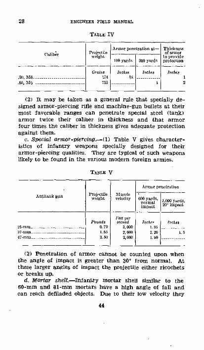
ENGINEER FIELD MANUAL
TABLE IV
Caliber Iwejight
.20, M6 ---- --- ---- 1-,4.30, M6 -...... 3..... i 174.50, M O ----- ------ ------- --- 75
Armor penetration at- Thicknes... __.. _______ Iof armor
to provide100 yards 30 yards Proteetion
Inches hIhes Inches
1 2
(2) It may be taken as a general rule that specially de-signed armor-piercing rifle and machine-gun bullets at theirmost favorable ranges can penetrate special steel (tank)armor twice their caliber in thickness and that armorfour times the caliber in thickness gives adequate protectionagainst them.
c. Special armor-piercing.-(l) Table V gives character-istics of infantry weapons specially designed for theirarmor-piercing qualities. They are typical of such weaponslikely to be found in the various modern foreign armies.
TABLE V
25-mm37-mm --------------47-mm --- ----------
(2) Penetration of armor cannot be counted upon whenthe angle of impact is greater than 30 ° from normal. Atthese larger angles of impact the projectile either ricochetsor breaks up.
d. Mortar shelt.-Infantry mortar shell similar to the60-mm and 81-mm mortars have a high angle of fall andcan reach defiladed objects. Due to their low velocity they
44
28

FIELD FORTIFICATIONS 28-29
have little penetrative power. On the other hand, they carryheavier bursting charges than artillery projectiles of corre-sponding weight and caliber. They are consequently espe-cially effective when used against light obstacles. and produceserious destructive effects when they fall within trenches.They are effective against surface and light shelters butare relatively ineffective against shell-resisting or bomb-resisting structures.
U 29. ARTILLERY AND AIRCRAFT-a. General.--(1) This para-graph covers penetration and crater effect of projectiles innatural earth and their effect upon various types of fortifi-cations. Effect of single artillery shells or bombs is statedwith a view to establishing in the mind of the engineer aconception of what constitutes safe construction and theresistance to fire various type of fortifications will present.
(2) Penetration and crater effect of projectiles are highlyvariable. Fortifications intended to resist continued bom-bardment must be designed with very large safety factors.Probability of such continued bombardment and probablepower and direction of projectiles likely to be used by theenemy must be fully considered.
b. Shell or bomb.-(l) If the projectile has an instanta-neous fuse, the detonation of the filling and bursting of thecase will occur so quickly that the projectile will not have timeto penetrate the object it strikes to any great extent anddepth of penetration will be indeterminate. If a fuse withsufficient delay is used and the angle of impact is not suchas to produce a ricochet, the projectile will penetrate theobject it strikes and detonate at a depth dependent on sev-eral factors, among which are nature of materials penetrated,terminal velocity of projectile, weight and cross section ofprojectile, strength of projectile case, and type of delay fuseused. Deep penetration in connection with long delay fuseswhere the projectile has attained its full penetration beforeit explodes serves to place the projectile where it is welltamped and the explosion probably does the most damage,that is, deep in parapets of trenches, inside casemates, andnearer chambers of underground shelters than the surface.Destructive effect is due to impact of the unexploded shell,
262375---40- 45

29 ENGINEER FIELD MANUAL
impact of the explosion, and shattering or disruptive effectof the explosion, including fragmentation and cratering.
(2) It is emphasized that these several factors whichproduce destructive effect of projectiles are defined only forgeneral information purposes. Sufficient experimental dataare not available to conclude that in any given case the vari-ous effects are cumulative or selective, and it is not possibleto state against which effect or combination of effects pro-tection must be provided. It is important to realize thelimitations imposed both by inherent uncertainties of warfareand difficulties surrounding research.
c. Ricochets,-The course followed by a projectile afterimpact on level ground depends on angle of impact, terminalvelocity, weight and dimensions of the projectile, its rota-tional motion (if any), and resistance of the ground. Ingeneral, action is as follows:
(1) If angle of impact is less than 7', projectile ricochets.(2) If angle of impact is between 7' and 25', shell either
ricochets after traveling a short distance in the ground, orremains in the ground at slight depth. Long pointed shellsusually show a greater tendency to come out of the groundthan short pointed ones.
(3) If angle of impact is between 25' and 40', projectilehas a tendency to turn toward the surface and deep pene-trations are not generally secured.
(4) If angle of impact is greater than 40', projectile fol-lows a straight course and reaches maximum depth consistentwith its terminal velocity, weight, form, and hardness of theground. This is the class of fire against which protectedshelters must be designed, and is in general characteristicof aircraft bombs on horizontal surfaces.
d. Penetratons.-(1) Formula.-Experimental data withrespect to penetration are inadequate.' The following em-pirical formula has been developed to give maximum pene-tration of projectiles in various materials, impact beingnormal. It applies both to artillery and aircraft projectiles.
46

FIELD FORTIFICATIONS 29
Results given by the formula will be considered only asapproximations.
p=0.23 W A KD2
in which P=Penetration of projectile in feet.W=Weight of projectile in pounds.D=Diameter of projectile in inches.A=A constant depending on striking velocity ac-
cording to the following table:
Velocity, feet per Velocity, ee per A Velocity, feet Asecnd - second second
130 ......... .3 657 ...... 77 1,180 -.......... .7190.7 ------ --- 7--20.-.........72 - 5.34 1,250.....-- --- 9.15
62 ....... 2.. 1 781 8 -........ 5.89 1,320 ........ 9. 54328 ---. 7------ L.6 854 -.......... .6.41 1,375 -........ 9.92
394 -............ 2.3690 -0-........ 6.92 1,445 ........ 10.29
460 ......... 7 985..........- 7.40 1,510 ......- 10. 6
525 ......... 58 1,050 7......... 87 | 1,575 -........ 10. 98592-- -------- 4.17 1,113 --........ 8.31 140...... 11.20
K=A constant depending upon nature of resistance shown inthe following table:
Mlaterial K _Material K
Concrcte masonry ......... 0.64 Sandy earth 2.. 94Stoe ........ O 94 louhed earth..... 3. 8
Brickwork .3 Clay soil ...............- 5.87
W and D are obtained from characteristic tables of theprojectile under consideration.
(2) Field artillery projectiles.-The following table givespenetration of field artillery projectiles in ordinary compactsoil:
47

29 ENGINEER FIELD MANUAL
TABLE VI-Penetration of field artillery projectiles
PenetrationCaliber striking Angle ofvelocity impact
Vertical Horizontal
Feet persecond Degrees Fed Feet
7-ramm ........- ----.......-------------... .. 730 45 4 4105-mm................. So 45 5 5155-mm-n.............. 770 45 7 78-inch.......... 790 45 9 9240-mm.... .......- -806 45 14 14
(a) Figures 17 and 18 give data secured by firing sand-loaded shell, observing point of fall, and then digging up theshell. These illustrations, together with the more extensiveexperiments upon which they are based, indicate that whenangle of impact is greater than 40° the projectile movesin a straight line until a considerable proportion of itsvelocity is lost. Then, particularly if it meets a somewhatharder stratum of material, it tumbles forward and comesto rest with its nose to the rear.
(b) To secure deep penetrations, large caliber howitzerprojectiles which strike the target with an angle of impactin excess of 40° are required. Weapons smaller than the155-mm howitzers and flat trajectory weapons are in generalineffective against heavy fortifications. Large howitzers ormortars are required to destroy well-constructed cut-and-cover and cave shelters.
(c) For thickness of cover required to provide protectionagainst various artillery projectiles see table XXVI, para-graph 53.
(3) Airplane bombs-(a) Data-Experimental data per-taining to the penetrations of airplane bombs in earth areinadequate.
(b) Strikingf velocity.-The trajectory of a bomb is a curvewhich would be a parabola in vacuo but in air is somewhatsteeper. The bomb loses speed in its initial direction butgravity gives it velocity toward the earth which increasesto a certain maximum limited by air resistance. Maximum
48
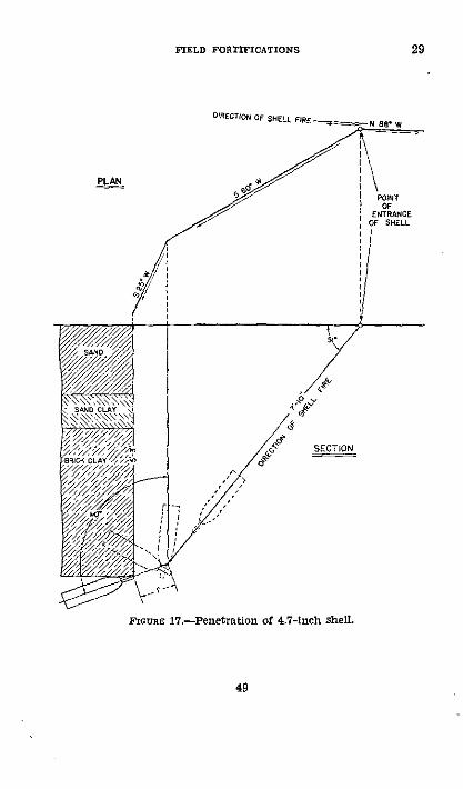
FIELD FORTIFICATIONS 29
N BES W
PLAN
POINTOF
ENTRANCEOF SHELL
SECTION
FrouRE 17.-Penetration of 4,7-inch shell.
49
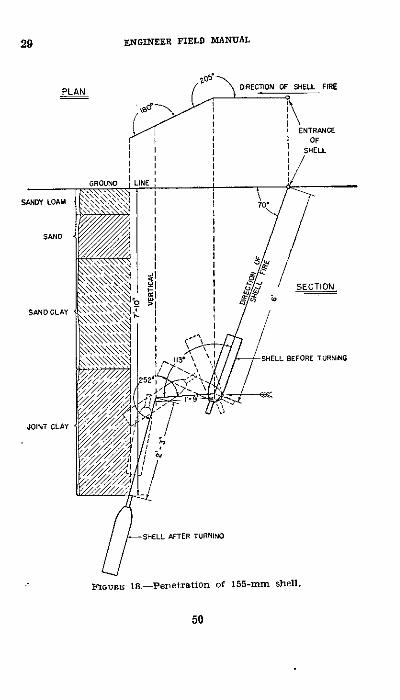
29 ENGINEER FIELD MANUAL
DIRECTION OF SHELL FIRE
SECTION
BEFORE TURNING
-SHELL AFTER TURNING
FIGURE 18.-Penetration of 155-mm shell.
50
PLAN
SAND CLAY
JOINT CLAY

FIELD FORTIFICATIONS
striking velocity depends on weight, shape, and dimensionsof the bomb, and prevailing atmospheric conditions. Fromthe point of view of structural protection, angle of impact,that is, the angle which the bomb makes with the verticalat the moment of impact, is important. Table VII givesapproximate striking velocity and angle of impact for bombsheavier than 100 pounds released from an aircraft flyinghorizontally at 200 miles an hour.
TABLE VII
Ang[l ofhteight of irp)a.t S rikingrele-sse with ,re- 'elofty
Feet perPerl Degrees srRcid1, 0(1) 46 3103, (XI0 33 52o5,009) 28 6107. 500 22 710
10. 0K) 19 80312. 500 17. 88015, lOd) 16 9O)
Taking all factors into consideration, it is safe to assumethat the maximum striking velocity of a high-explosivebomb that need be taken into account in structural defenseis 1,000 feet per second. The corresponding velocity for a2-pound incendiary bomb is about 400 feet per second.
(c) Types and dimensions.-For convenience types of HEbombs are classified with reference to weight of the containeras heavy-case, medium-case, light-case, and antipersonnel, asnoted in table VIIL
TABLE VIII
,tf r olllh tae Gross weightt___ _ _ _ -~~~~~~~~nlr
51
eay-se --------.............-.....-- .... Small --..... - 250 to 2,aO.Mediu-cll-rase......................2; S to 1000.Light- - --- --.............--............ ,23 to C) -0 to 2000.Antperasouul - ... .................... . 2t,
29

29 ENGINEER FIELD MANUAL
Table IX gives typical dimensions for a few bombs. Thefigures in brackets in the second column give the length ofbomb-carcass, that is, the part enclosing the charge. Thetail portion is often only a stream lining designed to givegood ballistics and to carry the fins.
TABLE IX-Typical dimensions of aircraft bombs
Bomb Length Diameter essure i
Pounds perFeet Inches square inch
2,000-pound, light-case ....-...... 14 (9) 24 4.4s,100-pound, heavy-case- ............ (4) 12 9.7550-pound, medium-as - ............ - 5 (4) 15 3.1220-pound, medium-case ..--........ 4pi(2) 10 2.8100-pound, medium case............ 4 (2) 9 1.620-pOUd, antipersonnel .............. 2 (1) 5 1.0
I Weight-maximum cross section area.
(d) Depth.--igure 19 gives approximate depth of pene-tration at zero angle of impact, for unit sectional density ofaircraft bombs. To obtain total penetration multiply valuefor penetration taken from the figure, by sectional pressuregiven in table IX. The formula in paragraph 29d conformsin general to the curves in figure 19.
(e) Referring to the formula given in paragraph 29d, thefollowing computations are made:
550-pound bomb, D=15 inches (from table IX).W=550 pounds (approximate).Assume sandy earth, K=-2.94: conditions giving 1,000
feet per second velocity of impact, then let A=7.50.p_ .23WAK .23X 550X 7.50X 2.94
Ds = = 12.4 feet.De 152
These results can only be accepted as approximations of pene-trations to be expected in a sandy soil.
(f) Lighter bombs have little penetrative power, even innatural earth. Larger bombs have sufficient penetrativepower to attack successfully protected shelters and buildings,
52

FIELD FORTIFICATIONS
APPROXIMATE DEPTH OF PENETRATIONFOR UNIT SECTIONAL PRESSURE OF BOMB
53
29
17--I,
-
it\pso S
° u
Z Ow
ao
r3IQ.
8 z-
200 400 600 800 1000 1200STRIKING VELOCITYz FEET PER SECOND
FrcraE 19.-Penetration of aircraft bombs.
ENGINEER FIELD MANUJAL
TABLE X.-Penetration of high-explosive bombs, andfrom foreign
B..bs
1 2 3 4
Lbs. In. Lblin2
Lb.110 7. I 2. 78 57220 . $ 2.92 I, 14.2 4. 2 360
2,20) 21.6 6. 01,200
4, 000 25.6 7.0 2, 200
IW
Fed13. 814.4
20.29.5
o( 33
2
I
f¢d
6
12. 519. S
Depth of pelletration
Slab sllpported ocrwhole of its srface
tl
Pi 0I ca ot S
7 o 9 10 11 12 13 14
_ _ _ = U= I'_
S. 69. 3
14.2
F]et5.66. 39.5
---
F 6t4.65.0
/:--
Fed1.31.3
2.0
2,200 83,00 5,700Lb/in' Lb1ica Feet Lb/in
2.0 1.3 1.2 0.S82.0 1.3 1.3 1.03.0 2.0 1. 1.5
-- -. 2.6 .= 3.3 =.
NOTES
All figul.r are feet anlli tItiis Of fele. cxclpt where sluown otherwise.
Figtlres in ctlumns 5.1, 1and 15- I19 ar applicable o an average striting elocity of820 feet ier seconll.
and the largest bombs may even penetrate heavy concreteand armored structures.
(g) Table X gives penetrations of bombs of various sizes inearth, gravel, concrete, etc., as well as thicknesses required tobe proof against them. These data are compiled chieflyfrom foreign sources and are, in general, based on theoreticalanalysis, since there is very little experimental informationon the subject.
e. Crater dimensions-(1) Light artillery proiectiles makerelatively small and ineffective craters for destruction of
54
29

FIELD FORTIFICATIONS
proof thickness to perforation and explosion, compiledsources
Thiekness just per-forated by pone-tration withoutexplosion
15 16 17
=L2,800 =2 2
Lb/in N Lb/il' Feet2.8 1.8 0.1..6 2.3 0.45.1 3.3 0.7. 5.1 0.,
1. 6.3 1.
Thicknessiustperforated,explosion
only
_ a
_ I 19
Feet Feet2.0 1. 2
3.6 2.654 4.16. 4.9
Froof thickness penetration and explosion
519526. 539. 0
.l 60
1'----
E
21
Feet18.0
24.6
22
Feet11.516.5
23 24 2i.
_=R.,00 o =3,5r u =5,700Lbin' Lb/in' Lblin
5.5 4.3 287.4 5. 6 379.0 I.o 4.0
12.0 6 6
Columns 18 and 19 apply to thickness of slab just "prforable" by explosion of abomb placed on the slab.
1. =Minimum crushing strength of oncrete, at age of 28 lays, in pounds per squareinch.
trenches and shelters. These projectiles are effective how-ever against exposed personnel and light obstacles designedto stop foot troops.
(2) Medium and heavy artillery projectiles are used fordestruction of shelters, trenches, and other types of fortifi-cations. Table XI below gives some idea of their relativeeffectiveness but it must be borne in mind that craters varygreatly with nature of the soil and depth to which theshell penetrated before explosion. This penetration is de-pendent upon both kind and setting of fuse and also uponthe soil. Tabular dimensions must be considered as average.
55
29

29 ENGINEER FIELD MANUAL
TABLE XI.-Probable size of craters in ordinary compactvirgin soil
(Light loam may double, loose soil triple these values)
Slighlt penetration AIedinm penetraionCalliber
Dhiameter Depth Diameter Depth
Fee Feet Feet Feet75-mm ......--........ . 4 1.5 5 3105-mm - -.............. 6. 5 2.5 7.5 3.75155-m . ............... 0 4 12 58-inch .--....... 11 5 4 13.5 5240-.mi ....-- ...... 14 4 15.5 5. 5
(3) Table XII gives average crater dimensions for aircraftbombs with instantaneous and delay-action fuses fallingon sandy loam.
TABLE XI.-Crater dimensions, sandy loam
Btoohl l Dtpth of Diameter Earth dis-crater at surfaee placed
IlitSh installtie 'oUs litse: Feet rlt Cbi ey ards)-pOld .. ................... 9 4
30-ound ................- ----- - 3 13 10MO-1poulld ................. 5 17 11,500--lound .............. 20 282,000-pond ---- -......... -----......... - - 22 47
1ith delay ation fuse:o 100pnd ......- ....--- 30
30-und- .........-------- 7 27 70t)-potd-.--- ------------ 10 37 170
1,100-pound 13 .....-------- i 3202,000-pound ................. 17 50 600
1. Trenches--Artillery fire upon trenches can overthrowparapets and interior slopes, obstruct loopholes, and displaceearth to the extent that the trenches are filled up or ob-structed. Only direct hits by light artillery shells, 75-mm to105-mm, produce appreciable results and fire of these gunsis effective only when single hits can be observed, or when
56
FIELD FORTIFICATIONS
the trenches are crowded with troops. Calibers of 155-mmand greater are normally required for destruction of trenches;155-mm or 6-inch howitzers usually available in large num-bers are the most important weapons used for such purposes.
g. Shelters.-(1) By use of protected shelters, it is pos-sible to maintain the physical condition and morale of troopsheld near their combat positions. Modern artillery fire,especially that of howitzers which can destroy troops in opentrenches, makes protected shelters an essential and possiblythe most important element in a stabilized fortified battleposition.
(2) Projectiles fired against protected shelters cause themost damage when they have penetrated deeply and explodeeither against or near the structure itself, the overlying ma-terial serving as a tamping so that the full force of theexplosion is expended upon the shelter. Conversely, if deeppenetrations are not secured and the projectile explodesnearer the ground surface than the shelter, this tampingeffect is decreased and the force of the explosion escapesupward. Damage to the shelter is thereby greatly reduced.Howitzers and mortars are very effective weapons for attackof shelters as their fire produces few ricochets and nearlyvertical impact with deep penetration.
h. Obstacles and entanglements.-(1) Light and mediumartillery and trench mortars are sometimes employed to cutgaps in wire entanglements. The object would be to adjusta beaten zone of fire upon the entanglement so that enoughshells will actually fall within its limits to effect destructionat the point desired.
(2) Requirements in rounds of 75-mm caliber to open agap about 25 yards in width and 30 yards deep are approxi-mately as follows:
2,500 .............3,000 ...............4,000 ......... ..
57
29

ENGINEER FIELD MANUAL
These requirements apply only to bands of wire not greaterthan 30 yards in depth located on practically level ground.Expenditure of such great amounts of ammunition on such arelatively nonremunerative target would rarely be justified.More ammunition must be expended to destroy deeper en-tanglements. Forward slopes increase and reverse slopes de-crease accuracy of fire and respectively decrease and increaseammunition requirements. In particular, reverse slopes serveto make cutting entanglements by gunfire a difficult and ex-pensive operation.
(3) Successive bands of wire should be sufficiently separatedso that artillery fire must be adjusted on each band. A seriesof separate bands are much more difficult for artillery to cutthan the same amount of material in a single band.
(4) Artillery firing upon entanglements uses high-explosiveshell with instantaneous fuses except when the angle of fallresults in ricochets. Then short delay fuses are used to securebursts as the projectiles rise.
(5) Types of obstacles other than wire entanglements areattacked by artillery in the same manner but in general donot resist fire as well. Antitank obstacles however requiretremendous expenditures of artillery ammunition for effectivedestruction and except in the case of fire against mine fieldson hard ground, such fire may leave the ground as difficult fortanks to traverse as before.
i. Concrete-1) Existing information on resistance of con-crete to shell fire has been assembled from observations madeduring the World War and from experiments in the case ofheavy, permanent fortifications and primarily from wartimeobservations alone in the case of field fortifications.
(2) When large shells are exploded against concrete forti-fications without penetration, severe vibrations are set up inthe structure. At times these vibrations cause a separationof the steel and concrete in the case of reinforced structureswhich lowers resistance to subsequent shots. The heavy ex-plosions coupled with the severe vibrations have a very ap-preciable destructive effect on morale of fortification garri-sons.
(3) Large caliber weapons firing base-fused projectiles withsolid heads and thick walls are required for destruction of
58

FIELD FORTIFICATIONS
concrete works. Against horizontal slabs or those slopingverylittle from the horizontal, high angle fire must be em-ployed.
(4) Concrete splinters badly under shell fire. Steps mustbe taken to protect the troops occupying concrete works fromflying fragments of concrete.
(5) Concrete fortifications protected by sand or earth aremuch more effective than those without such protective cov-ering. A layer of earth or sand tends to cause shells strikingat an angle of less than 40 ° to begin to turn toward the sur-face or to ricochet and hence reduces the angle of impactwith the concrete. The covering must first be blown off byshell fire before the concrete itself becomes vulnerable. Whena bomb or shell with a delay-action fuse is used however,there is danger that the earth cover will help to confine ortamp the explosion and increase its effect. A concrete burstercourse or detonating slab is valuable for this reason, since itsfunction is to detonate an instantaneous projectile or to pre-vent penetration of a projectile with a delay-action fuse.Walls which are perpendicular or nearly so are usually moreeasily destroyed by artillery fire than horizontal slabs. Notonly is it easier to secure angles of impact approaching 90'against such walls, but the sand, earth, and debris in front ofthem fall away quickly and expose the bare concrete.
(6) On the whole, concrete, either plain or reinforced, maybe considered as a most effective shell-resisting material,It is highly valuable for field fortifications whenever diffi-culties in connection with its use can be overcome. It isparticularly useful for machine-gun emplacements, observa-tion posts, shelters for machine-gun and other personnelthat fire from open emplacements, in burster courses madeup of many small, easily handled slabs, and for shelters thatmust be built above ground because of ground water or hardrock near the surface. See FM 5-10 for details of mixingand placing concrete in the field.
j. Masonry.-Stone and brick masonry show many char-acteristics similar to those of plain concrete but usuallyhave much less power of resistance. The quality and strengthof the mortar, interlocking bond used in laying courses, sizeand nature of stone or brick, all have a great deal to do withthe resistance of masonry.
59
29

29-31 ENGINEER FIELD MANUAL
k. Armor plate.-Armor has been used extensively hereto-fore only in permanent fortifications. Steel turrets havebeen found to resist even the most intense artillery bom-bardment very well. Due to their small size it is difficult tosecure direct hits on them. If they are properly designedeven direct hits by heavy shell frequently ricochet withoutdoing serious damage. Penetration is not essential to disablea turret however since it may become jammed by a direct hitor the supporting concrete so cracked or displaced that itcannot function.
i. Buildings and villages.--() Light and medium artilleryand small aircraft bombs are used against wooden buildings.White phosphorus smoke shell, incendiary bombs, and low-bursting shrapnel are effective in starting fires.
(2) Medium and heavy artillery and medium aircraftbombs are used against stone and brick buildings. Thecellars of masonry buildings are difficult to reach with artil-lery fire and frequently serve as effective shelters. The pos-sibility of being trapped or buried by debris may make suchlocations dangerous.
SECTION V
TRENCHES
· 30. GENERAL.-a. Trench construction may be consideredunder three heads, planning, tracing, and execution.
b. No work except that of the greatest urgency, notably thatin connection with hasty defenses, should be undertaken with-out careful planning. Even when some delay results from thisprocedure, the time lost is usually regained in execution ofthe project.
c. It may be enunciated as a general rule that no workshould be done at night that can be performed by day.
M 31. TRACE, TRACING, AND PROFILE.-a. The detailed locationof a trench on the ground or on a map is called its trace, andthe operation of laying out this location on the ground withsuitable marking devices is called tracing.
b. A profile is the cross section of the trench upon a verticalplane perpendicular to its direction. In order that discussionsfollowing may be clear, figure 20 shows nomenclature ofvarious trench features.
60

FIELD FORTIFICATIONS 32-33
· 32. NECESSITY FOR STANDARD TYPES.-Trenches constructedin contact with the enemy are usually the result of hasty andfrequently poorly coordinated efforts to obtain cover fromenemy fire. Such trenches except in the most mobile situa-tions must be developed into more complete and well-coor-dinated defensive systems. Both in this development and inconstruction of deliberate defenses out of contact with theenemy, a ready knowledge of certain standard trench tracesand profiles assists materially. Established standards, work-able and well-known with standardized material provided,give an objective toward which to work, though this ideal inmany cases may never be reached. Experience teaches thatpractice may be restricted to a limited number of simple forms
ire Crest /'-Ebow2est
Parapet o and _ _rada'C6roand Level HA~ ½ rzdLezeZ
Front S/a Are
Dfit
FITURE 20.-Trench nomenclature.
that will meet practically all situations. Standardization oftypes and materials and familiarity therewith by all combatpersonnel in such detail as their duties require result in uni-formity in training and practice, and economy in planning,execution, and supply of tools and materials.
· 33. CLASSIFICATION.-a. Direction (fig. 21).-With referenceto direction, trenches are classified as-
(1) Parallel, or those with general direction parallel to thefront, primarily for fire purposes but also providing for lateralcommunication.
(2) Approach, or those with general direction perpendicularto the front, for fire or communication purposes or for both,depending upon location and use in the defensive system.
262375'°-40-5 1Ova

33 ENGINEER FIELD MANUAL
(3) Switch, or those with general direction inclined to thefront; these connect two parallels for the purpose of preserv-ing continuity of the front in case of capture of a portion ofthe line. Switch trenches are primarily fire trenches but mayalso serve as communication trenches.
b. Employment.--With reference to employment, trenchesare classified as-
(1) Fire, designed primarily to provide cover for personnelwhen delivering rifle fire.
ENEMY
PARALLEL
PARALLEL
FrImua 21.-Trenches classified by direction.
(2) Communication, designed primarily to provide coverfor personnel moving from one part of an intrenched zoneto another.
c. Construction.-With reference to construction, trenchesare classified as hasty and deliberate. (See sec. I.)
(1) The principal works employed in connection with hastydefenses are hasty fox holes, trenches, and emplacements forautomatic weapons and light mortars constructed on the
62

FIELD FORTIFICATIONS
battlefield during mobile situations and usually under enemyfire.
(2) Deliberate trenches, constructed in connection withdeliberate defenses, are those not included in hasty trencheson the one hand, and not pertaining to permanent fortifica-tions on the other. Such trenches are usually more carefullydesigned than hasty types, are of stronger profile, and havegreater defensive power.
d. Sap.-A sap is a trench which is constantly prolongedin the desired direction by digging away the: earth-at itshead from within the trench itself. The earth is usuallythrown up as a parapet on the exposed flank and end,thereby giving additional protection to the working party.Construction of saps is referred to as sapping.
* 34. HASTY.-a. General.-The normal inclination of thesoldier pinned to the ground by enemy fire is to "dig in"to hold the ground he has gained. The result of his effortsis a hasty intrenchment or fox hole which he constructs withthe intrenching tools carried on the infantry pack. Thehasty trenches discussed and illustrated in this section aregiven as examples of good practice rather than as standardsto be followed rigidly. They represent excavations to gainhasty cover and to be developed eventually into forms approxi-mating deliberate trenches.
b. Skirmisher.-Figure 22 shows the simple lying-down orskirmisher trench dug by the soldier while under small-armsfire. It is ordinarily excavated from the prone position bysingle soldiers or by small groups working side by side. Insoft ground the soldier can mask himself from view fromthe front and secure appreciable protection from rifle andmachine-gun fire in from 10 to 12 minutes. The trenchshould be completed to the dimensions shown in less thanI hour when dug from a prone position with the infantryintrenching tools. It gives excellent protection against rifleand machine-gun fire, and to some extent against high-explosive shells. It is too shallow to protect satisfactorilyfrom shrapnel fire. Additional protection may be gained byplacing the pack, if carried, on the parapet.
c. Fox hole.-A more usual form of hasty intrenchment isthe fox hole shown in figure 23. It is started from a prone
63
33-34

34 ENGINEER FIELD MANUAL
or crouching position ( and may be developed successivelyto kneeling ® and standing ®, which gives satisfactory pro-tection against small-arms and light artillery fire. If en-gineer tools are used, not under harassing fire and in mediumsoil, the standing type can be completed by one man inslightly less than 1 hour. If infantry intrenching tools areused, the time to complete the standing type in mediumsoil is about 11/2 hours. If under harassing fire, time requiredfor completion will be increased, amount of increase depend-ing on degree of enemy interference.
~.9 ~' ~~~~-9
FicuaE 22.--kirmisher trench.
d. Shell hole positions.-Hasty entrenchment may take theform of an improved shell hole shown in figure 24. In thiscase the improvement consists of a recess hollowed in theforward slope to give an inconspicuous but effective firingposition with lateral protection from shell fragments andenfilade fire. In a shell-pitted area, shell holes afford quickprotection and a high degree of concealment for a smallexpenditure of labor.
e. Slit trenches.-Narrow trenches are used during mobilesituations for communication purposes and particularly forimmediate protection of personnel from artillery fire. Figure
64

FIELD FORTIFICATIONS
+ 6"
( Prone or crouching.
ENEMY
( Kneeling.
PARAPET
PROFILE@ Standing.
FIoURe 23.-Pox holes.
65
34

ENGINEER FIELD MANUAL
25 shows creeping (D and standing (D types. Figure 26 showsa deeper trench revetted with struts resting against oppositewalls and especially designed to protect against shell fire.Such a trench would be constructed only in short lengthsadjacent to the firing position; it is particularly applicablefor use as a shelter for machine-gun personnel. When spoil
FIGURE 24.-Improved shell hole.
from slit trenches is wasted at a distance from the excava-tion, the trenches become nearly invisible to ground observa-tion. Slit trenches are liable to be caved in by concentratedartillery fire thus becoming blocked as lines of communica-tion, and deeper types are more dangerous to their occupantsthan trenches of wider profile.
66
34

FIELD FORTIFICATIONS
4 Creeping.FIcGrE 25.-Slit trenches.
Material
( Standing.
MrIUs= 26.-Slit trench to protect against shell fire.
67
34

34-35 ENGINEER FIELD MANUAL
f. Shallow connecting trenches.-In order to provide forlateral communication along the line of fox holes, shallowconnecting trenches are dug. The trench shown in figure 27may be taken as typical. It has an average width of lessthan 2 feet and a depth of 1 to 11/2 feet, and requires about2 cubic feet of excavation per running foot of trench. Witha parapet about 9 inches high such a trench provides coverfor a man crawling on his hands and knees. When menare to occupy fox holes overnight, they usually extend thefox holes longitudinally, merging them with the shallowconnecting trench so as to lie prone while sleeping. Ifoccupied for several days, recesses with overhead cover maybe prepared. Care must be taken to dispose of the spoilfrom such digging so as not to attract enemy attention tothe work.
+9+ 9'
- -______ -r
FIGURE 27.Shallow connecting trench.
* 35. DELBERATE.--a. General.-In deliberate organizationof a position cohstruction of trenches is inseparably relatedto the other elements of field fortification. The entire de-fensive organization must conform to the tactical plan. Thecompleteness of the system will depend on the time,materials, equipment, and labor available.
b. Requirements.-A deliberate trench must fulfill thefollowing requirements.
(1) If a fire trench, it must have a good field of fire andpermit the maximum use of the defender's weapons. Itmust lend itself particularly to development of flank or cross-fire as well as fire to the front.
(2) It must provide protection against enfilade fire bymeans of frequent abrupt general changes in direction.Both parallels and approaches that may be enfiladed by
68

FIELD FORTIFICATIONS
observed enemy fire should make a general change in direc-tion at least once in 100 yards (see fig. 30).
(3) It must limit the effect of a bursting shell throughsubdivision by means of frequent changes of direction.
(4) In order to reduce the number of projectiles that mayfall directly into it, it must be as narrow as practicable, butit must not be so narrow as to make circulation within itunduly difficult or to render it easily blocked by caving.
(5) It must be sited to take advantage of natural drainageof the terrain and so constructed as to be adequately drained.
(6) It must be simple and easy to lay out and construct.(7) In addition to the foregoing requirements, if a com-
munication trench, it should be wide enough to permit twocolumns of men in single file to pass readily. If it is imprac-ticable to provide such a width throughout the length, itmust be widened at intervals to provide passing places.Where sharp changes of direction occur, the trench must bewidened so that a bulky piece of equipment such as an openlitter can be carried through easily.
(8) When the various platoon, company, and battalionareas of a defensive position are connected by parallelsand approaches, the defensive lines thus created should as-sume bold curves in making major changes in direction addi-tional to those prescribed in (2) above in order to increasethe enemy's difficulty of organizing bombardments and bar-rage fire.
c. Camouflage and concealment.--() All trenches shouldbe camouflaged or concealed from both air and ground ob-servation insofar as practicable or, failing that, rendered asinconspicuous as possible. It is impossible to camouflageextensive trench systems except in woods. Individual posi-tions within the trench system, for example machine-gunemplacements, shelters, and trenches approaching these posi-tions, can be camouflaged effectively and with great benefit.Such camouflage combined with continuity and uniformityin trace and profile of the uncamouflaged elements of theposition serves largely to withhold from the enemy knowledgeof the detailed location and numbers of the garrison. SeeFM 5-20.
69
35
ENGINEER FIELD MANUAL
(2) It is possible to conceal trenches from ground observa-tion to a large degree. Thus attacking infantry, althoughknowing the general location of trenches by means of air-plane observation, are confused as to their detailed locationand relative position and hampered in the attack. PFull ad-vantage should be taken of woods and brush. Freshly exca-vated earth that contrasts strongly with the surroundingsshould be covered with topsoil, sod, weeds, or brush. In gen-eral, avoid sharp or regular crest lines along parapet andparados; these lines should have the characteristics of sur-rounding terrain, and dimensions shown in illustrationsshould be modified as required to bring about this condition.Depressions in the parapet serve as firing embrasures, andthe parados should be sufficiently high to prevent the heads
FiGuaE 28.-Trench with irregular parapet and parades.
of the defenders of the trench from being seen in silhouette(see fig. 28).
d. Clearing field of fire.-(I) To comply with the con-dition that a field of fire of at least 100 yards is availablein front of each fire trench, a certain amount of clearingmay have to be done even in the most open country. Clear-ing a reasonable field of fire will ordinarily precede diggingcomplete fire trenches or will at least be done concurrentlywith such organized excavation. In areas organized forclose defense it is best to commence clearing work at thetrench and work forward. In delaying actions where fireeffect at long range is desired, any effort that can be directedtoward clearing should be employed on areas distant fromthe trench. Before commencing any work the question ofjust how much may be accomplished in the time availableshould be determined since a field of fire only partially
70
35

FIELD FORTIFICATIONS
cleared may give more cover to an attacking enemy than itdid in its original condition. It is desirable to leave a thinnatural screen to hide the position. A thin line of smalltrees or brush left standing may impede the enemy's observa-tion and at the same time not hinder fire of the defenders.
(2) Large scattered trees, if left standing, give less coverto an attacker than if cut down and are sometimes useful asrange marks. Unless they can be entirely removed or con-verted into dead abatis (see par. 43), only the lower branchesshould be cut off. Thick brushwood left standing may some-times serve as an obstacle but Infantry can usually pass withease any but the thickest growth of this kind. Therefore itis imperative to clear such growth. It is rarely possible ordesirable to undertake the wholesale clearing of woods, andthe work usually is restricted to clearing undergrowth andremoving lower branches of the larger trees. Narrow lanesrunning obliquely in front of a line to be defended may beentirely cleared through woods and swept by automaticweapon fire.
(3) The tools found useful in clearing woods are axes,brush hooks, canthooks, hatchets, machetes, mattocks, andcrosscut and power-driven saws. In situations where ex-tensive clearing is necessary those classes of the above toolsnot found in quantity in equipment of combat units shouldbe procured from the larger engineer supply establishments.Large trees may be cut down by the use of explosives butlack of large quantities of explosives for this purpose ordi-narily makes it impracticable.
(4) The following table for an area of 100 square yardswill be found useful in estimating time required for a givenclearing.
71
35
35 ENGINEER FIELD MANUAL
Description of area Mlet hod Manhours
Covered wait brash under 6 inches in di- Chopping or sawing trees 7ameter and containing 25 tecs6 inches to and clearing brush.2 feet in diahmeter (heavy clearing).
Covered with undergrowth and sonte trees .do ... 3.5not exceeding 12 inches in diameter(nmedium clearing).
Covered only withsmallbrush (light cle ar- ing brush -....... . 1.5ing).
(5) Walls should be demolished only when resultingdebris will not give more protection than the wall itself.Sufficient gaps must be made in the wall in any case to givethe defenders a clear view. Walls may be knocked down byuse of a tree trunk or rail as a battering ram, or by use ofpower machinery or explosives if available and situationpermits their use.
(6) The same principles apply to buildings as to walls.Low buildings may be knocked down. Larger buildings shouldbe burned and walls left standing. This will usually preventthe upper stories from being used as observation posts and atthe same time will not provide piles of debris in which theenemy may take shelter.
(7) Grain crops require somewhat the same treatment aswoods. If ripe and dry, they may of course be burned. Inthe absence of mowing machines or in situations where suchmachines cannot be used, lanes must be cut with scythes.
e. Standard traces.-(1) General.-Standard trench tracesmust conform to the requirements of b above. Of the fol-lowing standard types the one most suitable to the tacticalsituation and the terrain should be employed, special combi-nations and modifications being made to meet requirements ofspecial conditions. It is understood that the actual tracewill approximate only the geometrical precision shown infigure 29. Note in figure 29 that the fire bay for the octagonaltrace trench is given as 16 paces or 40 feet. This is based on

FIELD FORTIFICATIONS
an 8-man squad with allowance of 5 feet per man. If a largersquad such as one of 12 men is to occupy the trench, the firebay may be correspondingly increased to 24 paces or 60 feet.
(2) Octagonal.-The octagonal trace is an excellent typefor fire trenches in most situations. It provides excellentprotection and localizes results of bursting shells.
(a) Advantages are that it-1. Affords easy communication.2. Facilitates oblique fire along the front.3. Is an economical type to construct both as to labor
and material.4. May be provided with a continuous fire step.
(b) Disadvantages are that it-1. Lacks simplicity of detail.2. May be identified readily from the air as a fire
trench.(3) ZigZag-This trace gives less protection from enfilade
fire and shell bursts. Effectiveness may be increased by em-ployment of short tangents and by occupation of alternatetangents. Advantages are that it-
(a) Is the simplest and easiest to trace, construct, revet,and maintain of all types.
(b) May be adapted readily to terrain.(c) Is equally suitable for use as a fire or communication
trench.(d) May be provided with a continuous fire step.(e) Provides for both frontal and flanking fire.(4) Wavy.-Communication through this type is freer than
for any other type, and it is therefore specially adapted foruse for communication purposes. Advantages of the zigzagtrace largely apply to the wavy trace. Slightly more laborand material are required for its construction than for thezigzag.
(5) Echelon.-The echelon trace is used for fire trencheswhen ground must be gained either toward or away fromthe enemy without subjecting the fire bays to enfilade fire.It may also be regarded as a zigzag trace fronting obliquelytoward the enemy. It has advantages and disadvantages ofthat type of trace.
35

35 ENGINEER FIELD MANUAL
OCTAGONAL
ZIGZAG
WAVY
INH AGHLt Iit DIAGONAL HAKtSWITH THfl MOT IS VARIAILt. TOCOIIORM WITH G2000D teQOUIR'
. M 'HTS AND rtMY far.
t\
tCH tLONFloURE 29.Standard trench traces.
74

FIELD FORTIFICATIONS 35
(6) Modifications.-By modifying angles of the zigzag orechelon into curves, those traces assume characteristics of awavy trace. Such a modified or wavy trace, with the intro-duction of tangents at advantageous points, is a naturaldevelopment during hasty intrenchment.
J. Tracing.(l) General.-(a) Method.-Tracing trenchesshould always be supervised by an officer. If possible theyshould be traced with tape before arrival of digging parties.It is preferable to trace during the daytime. If enemy actionprevents daylight tracing, favorable times are twilight periodsat dusk or dawn. When a trench cannot be completely tracedduring the day it is usually possible to go over the groundduring the daytime and locate controlling points with stakes,stones, or nails to which pieces of paper or rags may befastened. This work should be done by an officer accom-panied by qualified noncommissioned officers who later willbe invaluable as guides for working parties. The salientpoints of the trench should be located with respect to easilyrecognizable landmarks, by azimuth and distance. If tape isnot available, the trace may be marked with wire, twine,stakes, or stones, or the working party may be extended alongthe line thereby indicating it. The last method is most diffi-cult to put in execution in the vicinity of the enemy andshould be used only as the final resort. In case this is at-tempted it will usually be necessary to have noncommissionedofficers pass along the line pacing off the distances and ver-ifying and correcting the position of each man.
(b) Controlling lines.-Parallels are traced along the edgenearest the enemy and approaches along the right hand edgewhen facing the enemy. Width of the trench is then meas-ured from the trace line by means of a gage stick, knownlengths of intrenching tools, or by pacing.
(c) Controlling dimensions.-Figure 29 shows dimensionsin feet and paces of the various standard traces. One paceis taken as 2.5 feet. It is habitual to trace trenches by pacingthe various distances, greater refinement in making measure-ments being unwarranted.
(d) General irregularities.-General changes in directionshould be introduced at intervals of from 75 to 125 paces as
75

ENGINEER FIELD MANUAL
indicated by figure 30 in parallels that may be enfiladed byobserved enemy fire, and in approaches.
(e) Tracing party.-The tracing party consists of 1 officer,1 noncommissioned officer, and 3 privates. It is equippedwith tracing tape, 6-inch nails or stakes, and hammers orhatchets.
(2) Octagonal.--(a) The officer lays the tape along thegeneral trace line established by the front edges of the firebays.
(b) The noncommissioned officer accompanied by one pri-vate follows the general trace established by the officer, roll-ing up the tape as he goes. At the same time he paces offdistances alternately of 16 and 6 paces and indicates to theprivate the ends of the fire bays. The private then drivesstakes at these points. The noncommissioned officer also indi-
-U -.ea iknrreula race linte
Fiou S 30.-General irregularities introduced in wavy and zigzagtraces.
cates to the private points where offsets are to be taken. Theprivate then paces 6 paces to the rear from these offset pointsand drives a stake, thus marking the ends of the rear bay.The noncommissioned officer makes minor adjustments asrequired.
(c) The two other privates stretch a tape along the linethus established, making a round turn at each corner. Theyprovide additional stakes if required.
(3) Zigag.-(a) The officer lays the tape along the generaltrace line which indicates general direction of the trench,providing slack for the zigzags.
(b) The noncommissioned officer accompanied by one pri-vate follows along the general trace pacing off distances of16 paces and. indicating these points to the private. Theprivate takes an offset of 6 paces to the rear at every otherpoint so indicated, and drives a stake. He drives a stake on
76
35

FIELD FORTIFICATIONS
the general trace at the other 16 pace points. The noncom-missioned officer makes minor adjustments as required.
(c) The two other privates stretch the tape taut betweenstakes, taking a round turn over each stake. They provideadditional stakes as required.
(4) Wavy.-(a) Duties of the officer and noncommissionedofficer are as indicated for zigzag in (3) above.
(b) One private drives a nail or stake at each corner lo-cated by the noncommissioned officer. The other two privatesdrive stakes to convert the straight portions of the zigzaginto curves, and stretch the tape along the line of stakes thusestablished. About five or six stakes are required between thecorner stakes located by the noncommissioned officer to pro-vide the requisite sinuosity,
(5) Echelon.-The echelon trench may be traced as a zig-zag trench running obliquely to the front or the officer incharge may. indicate the various corners, the detachmentthen stretching the tape between them.
(6) Tracing without tape.-The same methods may be fol-lowed when tracing without tape as when tracing with tape.corners and intermediate points being marked by stakes orstones.
(7) Variations.-Other methods may be devised by anofficer tracing trenches either with or without tape. A rigidconformity to forms and dimensions shown by figure 29 maynot always be desirable. Full utilization of the defensivevalue of terrain and of all terrain features that may serveto conceal the trenches constructed, constantly observingthe general provisions given in b above is of much greaterimportance. In case of a variation from standard dimensions,the officer specifies to the noncommissioned officer the exactlength of fire bays, traverses, or diagonals he desires to use.
9. Standard proflles.--(1) General.Trenches constructedin the face of the enemy and under difficult conditions neces-sarily vary in profile in order to meet those conditions.Standard profiles are prescribed for use except where unusualconditions require modification or do not admit completeexecution. The standard profiles shown should be used in allinstruction and training. They give a comparatively widetrench. Experience teaches that the advantage of additional
262375 -40-- 6 77
35

ENGINEER FIELD MANUAL
protection offered by a narrow trench is more than offset bythe freedom of circulation provided by the wider trench andby the fact that the wider trench is not easily blocked bycave-ins. Officers and men should familiarize themselves withthese profiles so as to avoid confusion and loss of time inconstructing trenches under difficult conditions. It is under-stood that the exact geometrical preciseness shown in theillustrations will never be attained in actual practice. Refer-ence is made to figure 20 showing terms adopted for the vari-ous parts of, a standard trench., Standard profiles are shownin figures 31 to 35. Development of a simple standing trenchinto the A or B standard type is shown by figure 35.
(2) Simple standing trenchl (fig. 31) is Unrevetted and pro-vides no room for circulation in rear of the firing line. It is
t ( t
Fowun 31-Standard profile, simple standing trench.
the first profile sought when trenches must be constructedrapidly, but should be developed to type A in order to providebetter cover and communication as soon as time, labor, andmaterial permit,
(3) Tvpe A (figs. 32 and 33) is unrevetted (except for para-pet of fire trench and fire step) and therefore is the standardfor hard ground where excavated slopes will stand withoutrevetment. In soft ground this profile should be developedto type B as soon as time, labor, and material permit.
(4) Type B (figs. 34 and 35) is deeper and wider than typeA, with lower half of the trench revetted throughout withA-frame supports and the upper half unrevetted, It haswide berms and easy slopes so as to avoid blocking of thetrench by cave-ins under shell fire.
'8
35
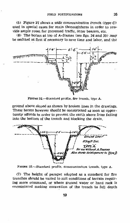
FIELD FORTIFICATIONS
(5) Figure 37 shows a wide communication trench (type C)used in special cases for main thoroughfares in order to pro-vide ample room for increased traffic, litter bearers, etc.
(6) The berms at top of A-frames (see figs. 34 and 35) maybe omitted at first if necessary to save time and labor, and the
FLour 32.-Standard profile, fire trench, type A.
ground above sloped as shown by broken lines in the drawings.These berms however should be constructed as soon as oppor-tunity affords in order to prevent the earth above from fallinginto the bottom of the trench and blocking the drain.
Ad.\ X / TS -t lc
.brWvWthoutlAnt metAlro /ho" dertopmentr to Sped
FIorUE 33.-Standard profile, communication trench, type A.
(7) The height of parapet adopted as a standard for firetrenches should be varied to suit conditions of terrain requir-ing more command, or where ground water or hard rock isencountered making excavation of the trench to full depth
79
35

ENGINEER FIELD MANUAL
frett , iO.Ssy ftfxt.
fr' Z.s Wi,t A Fr-
ror ure w11 tn 'A fi~mr
cltraS 34-Standard profile, fire trench, type B.
r; Z96fI.Exc
brwe t2hArameforCt usevitihArrawes
hors~r 35.-Standard profile, communication trench, type B.
Partds
fl7re;3D1r from Cd'tdpond o a C
.. A . -A',- ,fi ·· t *,
PIoTRE 36.-Simple standing trench showing development intostandard fire trench, types A and B.
80
35
." , te
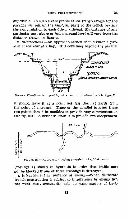
FIELD FORTIFICATIONS
impossible. In such a case profile of the trench except for theparados will remain the same, all parts of the trench bearingthe same relation to each other, although the distance of anyparticular part above or below ground level will vary from thedistance shown in figures.
h. Intersections.-An approach trench should enter a par-allel at the rear of a bay. If it continues beyond the parallel
ad,?;+ -S ~PE '(t Jiroad admmuncatiotn ten&c
FoIGer 37.-Standard profile, wide communication trench, type C.
it should leave it at a point not less than 25 yards fromthe point of entrance. Trace of the parallel between thesetwo points should be modified to provide easy communication(see fig. 38). A better solution is to provide two independent
25 YOS
FImurE 38.-Approach crossing parallel, octagonal trace.
crossings as shown in figure 39 in order that traffic maynot be blocked if one of these crossings is destroyed.
i. Intrenchment in presence of enemy.--When deliberatetrench construction is subject to interference by enemy fire,the work must necessarily take on some aspects of hasty
81
35
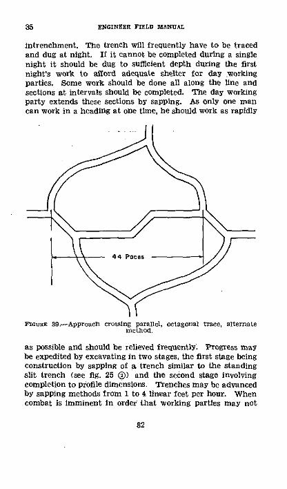
35 ENGINEER FIELD MANUJAL
intrenchment. The trench will frequently have to be tracedand dug at night. If it cannot be completed during a singlenight it should be dug to sufficient depth during the firstnight's work to afford adequate shelter for day workingparties. Some work should be done all along the line andsections at intervals should be completed. The day workingparty extends these sections by sapping. As only one mancan work in a heading at one time, he should work as rapidly
FIGURE 39.-Approach crossing parallel, octagonal trace, alternatemethod.
as possible and should be relieved frequently. Progress maybe expedited by excavating in two stages, the first stage beingconstruction by sapping of a trench similar to the standingslit trench (see fig. 25 () and the second stage involvingcompletion to profile dimensions. Trenches may be advancedby sapping methods from 1 to 4 linear feet per hour. Whencombat is imminent in order that working parties may not
82

FIELD FORTIFICATIONS 35
be too fatigued to engage the enemy with effect, reliefs ofnot more than 4 hours should prevail.
j. Planning and reconnaissance.-(I) Deliberate intrench-ments should always be carefully planned. Planning exten-sive intrenchments presupposes prior determination of theirgeneral location, extent, and mission. These points areproperly covered in orders issued from higher headquartersof combat units to the officer responsible for constructionof the works.
(2) The officer directed to take charge of construction ofintrenchments is normally an engineer for extensive orcomplicated trench systems out of contact with the enemy,and an officer from the combat unit that is to do the workfor lesser undertakings. Upon receipt of orders to proceedwith the work he should visit and reconnoiter the site by dayif possible. He should take with him a party to assist intracing the works and later to serve as guides for workingparties, if required. Preliminary reconnaissance having beencompleted, the intrenchments should be traced. When theycannot be traced completely by day it is frequently possibleto go over the ground and mark controlling points. Loca-tions of these points and length and direction of majorlengths of the trenches to be constructed should be tied in tolandmarks by azimuths and distances.
(3) Data determined as a result of reconnaissance shouldbe-
(a) Sketch or overlay on an existing map or a positionsketch showing general location, length, and azimuth of theprincipal straight stretches of the trench and relation ofcontrolling points along it to existing works.
(b) Decision as to profile to be used.(c) Estimate of nature of soil and proper proportion of
tools.(d) Estimate of total amount of material to be excavated.(e) Estimate of time, men, tools, and materials required.(f) Decision as to necessity for a covering force to protect
the laboring force.k. Estimates of time, labor and tools.-(1) If length
of the general trace of a trench line is known, actual length
83

35 ENGINEER FIELD MANUAL
of trench to be dug may be found by multiplying by theappropriate coefficient, as follows:
Type of trace Coefficient
Octagona l ........... .. 1.09Zigzag .....-...... 1.07Echelon ------- ------. s----- ----- ------- -------- 1.08Wavy - - . - 1.11
I This will vary considerably with the actual trace.
(2) Table XIII gives figures for use in estimating time,labor, and tools required for trench construction, It is appli-cable to day work by inexperienced men using pioneer tools.The figures given represent the best performance that can beanticipated from large groups of soldier labor.
TABLE XII.--Day work, single relief, using pioneer tools'
Number cubic feet of exeavation per man in-
Soillhr. 2hr. 3hr. 4br. 5hr.r. r. 7hr. Slhr
Arl a . .. .- 15 24 32 40 47 54 61 67Average 23 37 49 60 71 81 9t 100lightaa---------------- 30 50 6a6 80 94 108 121 133
I This table contemplates a rest of 10 minutes every hour after the first hour.2 All must be loosened with a pick. Requires 2 picks to I shovel.3 Requires little or no picking. Requires 1 pick to 2 shovels.
(3) Estimates must be reduced from the totals indicatedby table XIII for night work, rain or other unfavorableweather conditions, and annoyance by enemy fire, in thediscretion and based upon experience of the estimating offi-cer. Night work is about two-thirds as e/tective as daywork. Night work should be planned to take full advantageof moonlight hours and duration and phase of the moon andprobable cloud and weather conditions should be consideredcarefully when preparing estimates.
84

FIELD FORTIFICATIONS
(4) A 5-foot length of trench (measured along the frontedge of the trench) is a standard task for one man; the menshould be spaced so that they can work efficiently and safely.In special cases when speed is essential and daylight workis possible, men may be spaced at 3.5-foot intervals. Themen then should work at right angles to the axis of thetrench as much as possible.
(5) If ample tools are available each man should be issueda pick and shovel. Otherwise, picks or shovels should beissued to men in the ratios indicated by table XIII, dependingon nature of the soil.
(6) Experience teaches that soldier labor and untrainedmen in general become excessively tired after more than4 hours' continuous work, and their output thereafter dimin-ishes very rapidly. Men may be worked in one or in twoor more reliefs. In the first case men work continuouslywith 10 minutes' rest out of every hour. In the second casethere are two or more complete crews which relieve eachother at intervals of several hours. A given piece of workmay be completed more quickly using two reliefs, but com-pared to a single relief is not economical in manpower. Themethod of "doubled crews" may also be used. Here the menwork in pairs; one man works as hard as he can for 4 or 5minutes and then is relieved by the alternate man of thepair. The efficiency of a double crew is about 10 percentmore than for one relief in light soil for 1 hour's work andabout 30 percent more in hard soil for 8 hours. When work-ing without enemy interference, in a standing position engi-neer tools are about 30 percent more efficient than infantrytools.
(7) With soldier labor, assignment of a definite task andprovision for relief of the working unit upon completion ofthe task usually produce the best results. Under taskassignments the output for any given period of time usuallyexceeds that indicated by table XIm. Tasks should be as-signed by individuals, squads, platoons, or companies. As-signments should be such that each unit can return to campor quarters when its task is completed. Great care must beexercised and the best experience available utilized in assign-ing tasks; once established, they should not be altered unless
85
35

ENGINEER FIELD MANUAL
found to be extremely unfair or entirely impracticable ofaccomplishment. With soldier labor, one-relief task assign-ments requiring approximately 4 hours for their completionare recommended. Such a procedure results in a maximumvolume of excavation per man and Permits employment oftwo reliefs, for example, one in the forenoon and one in theafternoon if work can be done during daylight hours.
(8) Experienced laborers using commercial tools which arelarger and heavier than the pioneer tools can exceed by from50 to 100 percent the quantities given in table XIII. Suchlabor should be worked an 8- to 10-hour day. Trained labortroops to be used continuously for pick and shovel workshould be supplied with commercial tools and worked onan 8- to 10-hour daily schedule.
(9) While deliberate intrenchments can be constructed withthe infantry tools carried on the pack, these tools are rela-tively ineffective as compared with pioneer tools. The useof infantry tools on deliberate works should be avoided ifpossible, but they are normally employed in connection withhasty intrenchments.
(10) Table XIV gives time required for completion ofType A and B trenches. It is computed from table XIII.
TABLE XIV.-Hours required to completetasks; or if not completed, percentageof day work, using pioneer tools
31/2-foot and 5-footfinished in 8 hours
Type A unrevetted
Fire trench
One relicf Two reliefs
3a 5 3a 5feet feet feet feet
85% 60% 5. 5 7. 255.75 50% 3.5 5.0375 6.0 2.5 3. 5
Colnnlunication trench
One relief Two reliefs
334 5 3,A 5feet feet feet feet
7.0 75% 4.0 5.754.0 6.75 2.75 4.0275 4.5 2.0 30
Type B revetted
Fire and communi-cation trench
One relief Two]iefs
3' 5 33_ S:ft fet feet feet
65% 45% 7.00 8o0%s95% % 4. 6.56.00 5% S. 0
86
Nature ofso.i
Hard .Average.-Light....
35
I

FIELD FORTIFICATIONS 35-36
(11) When preparing estimates the following points shouldbe kept in mind:
(a) Do all work by daylight if possible.(b) When night work is required, do some excavation
along the entire length of the trench the first night; at leastcomplete section C, figure 36, which should require from 2to 6 hours' work for 5-foot tasks. Complete the type Aprofile the first night if possible.
(c) In general, when using soldier labor, use the one-relieftask assignment system. The tasks should require approxi-mately 4 hours for their completion and the standard 5-footassignments should be employed. Use two such reliefs withtask assignments when speed is essential and plenty of menare available.
(d) Use the 32-foot assignment only in case of emergency.(e) Increase estimates for labor and tools by at least 5
percent to allow for contingencies.(2) Request covering force, antimechanized, antiaircraft,
and gas warning personnel for protection of laboring forcewhen presence or activities of the enemy require it.
U 36. DRAIrAGE.--a. General-(I) Drainage of trenches is ofthe utmost importance. Improper drainage not only mayhave serious effects on health of the occupants but mayinterfere so much with use of trenches as to contribute ma-terially to the failure of military operations.
(2) The question of proper drainage must be consideredwhen siting trenches, during their construction, and alsoduring their occupation. A small amount of forethought maylater save a large amount of labor.
(3) Drainage plans should be prepared before constructionis commenced. If this has not been done they should beprepared by the officer commanding the occupying troopsas soon as possible. Drainage plans should be prepared andthe work these plans call for completed during dry periodsso that the trenches may be of use during wet weather.
(4) Surface water must be excluded. It is much easier toprevent its flow into the trench than to remove it once ithas gained access.
87

36 ENGINEER FIELD MANUAL
(5) Water may be disposed of by-(a) Drainage ditches that conduct the water by natural
flow into nearby drainage lines.(b) Sumps that either penetrate permeable soil and dis-
pose of the water by percolation or collect the water fordisposition by pumping, siphoning, or bailing. Combinationof sump for collecting the water over a drill hole penetratingpermeable soil, and disposing of same by percolation throughthe drill hole.
(6) Sumps should never be installed when the water can bedisposed of by drainage ditches of reasonable length.
(7) A moderate slope of 1 percent, that is, 1 foot in 100feet or 0°35', is desirable. If the slope is excessive, damageby erosion may result.
(8) The eye cannot be relied upon to determine differencesof level in connection with drainage. A carefully adjustedclinometer, spirit level, or in important cases, a surveyor'slevel should be used.
(9) Presence or absence of underground water when indoubt should be determined by digging test pits beforestarting construction of extensive field works. In some lo-talities it is so abundant or so close to the surface as torequire use of high parapets or breastworks instead oftrenches. Except in such localities ground water is unlikelyto interfere with the works discussed in this section. Withrespect to construction of deep cave shelters, however, thesubject is more important.
b. Sites.--() Trenches should not be located in marshyor boggy ground unless it is absolutely unavoidable.
(2) Communication trenches should not be located in thebottom of valleys or gullies but should be placed along theside slopes.
(3) Special care must be taken to site trenches so thatall parts can be easily drained toward naturally low pointsin the line, avoiding any unnecessary sag which will bedifficult to drain later (see fig. 40).
(4) Never site a trench exactly along a contour, but giveit enough slope to carry the water in the desired directionas shown in figure 40.
88

FIELD FORTIFICATIONS
c. Construction.-(1) Plan for drainage from the begin-ning. First, start the drainage ditch or sump, always keep-ing progress of its excavation in advance of that of thetrenches draining into it.
\ < V e'~ch n¢
FrGURE 40.-Siting trenches to eliminate low spots.
(2) Complete excavation progressively upgrade when prac-ticable so as to avoid formation of undrained pockets in thebottom of a partially completed trench.
(3) Gutters or intercepting ditches should be providedon the uphill side of trenches for collecting surface waterand conducting it to a natural watercourse. The parades
WOODEN FLUM
FiotrE 41.-Surface water carried over trench.
sometimes may be made to serve this purpose. If necessary,these surface ditches are carried over or under the trenches(see figs. 41 and 42).
d. Maintenance of system.-(1) Maintenance of the drain-age system is the duty of the troops occupying the sector.Responsibility for maintenance of drainage of all trenches
89
36

36 ENGINEER FIELD MANUAL
within a given area devolves upon the commander of thatarea., . This responsibility includes communication trenches,the drainage of which is as important as that of occupiedtrenches and is more apt to be neglected.
(2) In a sector which is to be occupied for sometime, a smallforce should be detailed to inspect and maintain the drain-age system. It should be charged with keeping all drainsand sumps clear, including the intercepting ditches forsurface drainage.
(3) -All caving surfaces must be repaired, and earth throwninto trenches by shell explosions must be removed at once.Constant attention to this matter will save a large amountof labor later, as water backing up in a trench will causeadditional caving.
FIGURE 42--Surface water carried under trench.
(4) In level country sign boards marked DRAIN and bear-ing an arrow showing direction of flow should be placed atappropriate points in trenches in order that this directionmay be known when cleaning out ditches.
(5) An excellent way to determine measures necessary formaintenance of the drainage system is to inspect it duringor immediately after a rain.
e. Flooring.-(1) Trench boards (fig. 43) when availableshould be placed in the bottom of all trenches, except onrock. In firm ground they may be laid without specialsupports, or merely with the ends supported on short boardslaid transversely across the bottom of the trench. In softground they should always be supported on trestles (fig. 44)or on the A-frames used for revetting (see figs. 47 and 48).Trench boards are lightly fastened down as they must not
90
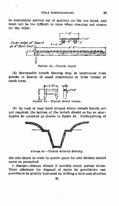
FIELD FORTIFICATIONS
be continually getting out of position on the one hand, andmust not be too difficult to raise when cleaning out drainson the other.
OuCer-edge of board 2 an _6_{6 -r 4"lQam 7n0 _ e6',-¢
FoIURE 43.-Trench board.
(2) Serviceable trench flooring may be improvised fromplanks or boards of usual dimensions or from trunks ofsmall trees.
't it'A4'
FIGURE 44-Trench board trestle.
(3) In rock or very hard ground where trench boards arenot required, the bottom of the trench should as far as prac-ticable be crowned as shown in figure 45. Undercutting of
FIGURE 45.-Trench without flooring.
the side slopes in order to secure space for side ditches shouldnever be permitted.
1. Sumps.-Sumps should if possible reach porous strata.Their efficiency for disposal of water by percolation cansometimes be greatly increased by drilling a hole and shooting
91
36
ENGINEER FIELD MANUAL
a small charge of explosive some distance below the bottomto loosen up the ground. They can be located underneaththe trench boards or in an offset.
g. Pumping and bailing.-(l) Pumps are sometimes neces-sary for removing water from sumps. Classes of pumps fur-nished complete with suction and discharge hose usuallyavailable are-
(a) Hand-force, to be operated inside the trench by oneor two men.
(lb) Hand-suction, to be operated outside the trench byone or two men; limit of suction approximately 16 feet.
(c) Gasoline-driven force, for use in special cases; limitof suction approximately 20 feet.
(2) Bailing scoops or galvanized iron buckets may be usedfor bailing out sumps.
E 37. REVETMENTS.-a. General(-) A revetment is a re-taining wall or facing for maintaining earth slopes at asteeper angle than their natural angle of repose.
(2) Revetments may be classified as-(a) Retaining wall type, which is self-supporting and acts
on the gravity principle for retaining walls. It is largelyused in connection with fills, parapets, and breastworks.
(b) Surface or superficial type, which must be supportedand acts largely by protecting revetted surface from disinte-grating and erosive effects of weather and from abrasion dueto occupation of trench. When strongly constructed it mayalso serve to retain loose materials and prevent settlement. Itis used principally in cuts.
(3) A good revetment must possess-(a) Simplicity of detail.(b) Adaptability to available materials.(c) Ease of fabrication and erection.(d) Low fragmentation under shell fire.(e) Ease of removal from obstructed trenches.(4) In general, revetments should be constructed only
when obviously required and should not be more extensivethan necessary. They require a great deal of labor andmaterial and should therefore be avoided if possible. On theother hand, during long occupation of trenches and when
92
36-37
FIELD FORTIFICATIONS
time, labor, and materials are available, extensive revetmentsmake the garrison more comfortable and reduce maintenance.
(5) If sides of the excavation are carefully sloped theamount of revetment required is greatly reduced. Unevennesscauses rain to lodge in or erode the surface, to soak into theearth, and results in rapid disintegration of the slope. Thesteeper the slopes of a trench the greater is the need forrevetment to prevent them from caving.
(6) The interior slope of the parapet of fire trenches (notthe entire front slope) is always revetted. In addition, onlythe lower 2 or 3 feet of a trench usually require revetment.Fbr standard profiles as shown in figures 32, 34, and 35, thisinvolves revetment to the level of the fire step or lower berm.Such revetment supports portions of the trench subject tothe most wear, preserves drainage, is seldom injured by theenemy's fire, and preserves the profile of the bottom of thetrench for clearing after a cave-in.
b. Retaining wall types.-As these revetments must be self-supporting they should always take the form of a properlybuilt retaining wall. The thickness at any level should beat least one-half the remaining height and the average thick-ness not less than one-third of the total height. Amount ofexcavation required for retaining wall types is considerablygreater than for surface types.
(1) Sandbag.-This type is easily and quickly constructed,does not splinter from shelling, and is especially useful foremergency work, for repairs, crowning, and revetting theinterior slopes of parapets.
(a) The standard sandbag is 14 by 261/2 inches flat, withan attached tie string 3 inches from the top of the bag.When filled three-fourths full, each bag weighs from 45 to75 pounds depending upon material and whether it is wet ordry, averaging approximately 65 pounds, and fills a spaceapproximately 43¾ by 10 by 19 inches. Thus 10 linear feetOf parapet revetment for type A fire trench, as shown infigure 32, requires 24 sandbags, and 10 linear feet of revet-ment for front slope and parapet of Type B fire trench, asshown in figure 46, requires 132 sandbags.
262375'40 7
37
93
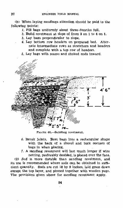
ENGINEER FIELD MANUAL
(b) When laying sandbags attention should be paid to thefollowing Points:
1. Fill bags uniformly about three-fourths full.2. Build revetment at slope of from 3 on 1 to 4 on 1.3. Lay bags perpendicular to slope.4. Lay bottom row headers on prepared bed. Alter-
nate intermediate rows as stretchers and headersand complete with a top row of headers.
5. Lay bags with seams and choked ends inward.
.- 46"'
3 t
'"*2' 5" 'FIGURE 46-Sandbag revetmnent.
6. Break joints. Beat bags into a rectangular shapewith the back of a shovel and tuck corners ofbags in when placing.
7. A sandbag revetment will last much longer if wirenetting, preferably doubled, is placed over the face.
(2) Sod is more durable than sandbag revetment, andits use is recommended where sods can be obtained in suffi-cient quantity. Sods are cut 18 by 9 inches, laid grass downexcept the top layer, and pinned together with wooden pegs.The provisions given above for sandbag revetment apply.
94
37

FIELD FORTIFICATIONS
(3) Stones and bricks may be used for revetment in theform of retaining walls laid dry, in which case a slope ofnot steeper than 4 on 1, laid at right angles to the face, andbroken joints are especially important. Due to danger fromflying splinters in case a stone revetment is hit by a shell, itsuse is not recommended where other material is available.If used in a parapet it should always be crowned with earth-filled sandbags.
c. Surface types-(1) General.-This form of revetmentconsists of two parts, the revetting material which retains
III- 3 ' O '
4'
IE 2o'0"- I STRAP IRON K: X4i'x4' 7"I I IF AVAILABLE
SIDE ELEVATION END ELEVATIONFlonaE 47.-Standard A-frame.
the earth, and the supports which hold the revetting ma-terial in place. It is most useful in retaining slopes oftrenches since little additional excavation is needed.
(2) Supports may be standard A-frames, pickets, or struts.(a) A-frames.--Standard A-frames are used in the bot-
tom third of the trench, placed 3 feet center to center andsupport material described above (see figs. 47 and 48),Methods of placing these frames around corners in octagonaltrenches are shown in figure 49.
95
37

ENGINEER FIELD MANUAL
-'~____ 4' 6"
1- .A-- ' E" 6 - 'STRAP IRON WY.Ii'i (I IF AVAILABLE
I~~~~~~~~~~~~~~~~~~~~~~~~~~~~~~~~~~~~~~~~~~~~~~~~~~~~~~~~~~~~~~~~~~~~~~~~~~~~~~~~~~~~~
SIDE ELEVATIONP'IGItE 48.-Special A-frame for Use
type C.
END ELEVATIONin communication trench.
PARAPET
STANDARD A FRAMPLACED 3 C TO C
PARADOSFIoURE 49.-Placing A-frames.
96
* I
6' 0"
37

FIELD FORTIFICATIONS
An estimate sufficiently accurate for all practical pur-poses of the number of A-frames and trench boards requiredfor any given frontage of trench may be made as follows:
1. A-frames.Octagonal trace=
[frontage (in yards) +10 percent (to convert frontage tolength of trench) +10 Percent (to provide for angles intrench) ]
Zigzag, wavy, and echelon traces=frontage (in yards) +10 percent
2. Trench boards.Single walkway=
Number A-frames2
Double walkway=Number A-frames.
Thus a frontage of 1,000 yards of octagonal fire trench typeB, using standard A-frames and single walkway requires:
A-frames = [1,000+100]!110 percent = 1,100+110 =1,210.
Trench boards= '2 1 =605.For the same frontage of wavy, communication trench, type
C (wide communication trench), using special A-frames anddouble walkway:
A-frames=1,000+100=1,100.Trench boards=1,100.
(b) Pickets.-If A-frames are not available and the soilpermits, the revetment may be supported by means of picketsdriven into the bottom of the trench and braced, as shown infigure 50. Anchored pickets are used when revetting frontslopes of fire trenches (fig. 51), or in other special cases wherehigh revetment is required. Revetting pickets should be from2 to 3I/2 inches in diameter, straight, pointed at the small end,and driven into the ground from 1 to 1'/2 feet. Light angle-iron pickets may also be used. Lateral spacing of picketsvaries with soil and character of working materials. Forexample, burlapped chicken wire requires more closely spacedsupports than sheets of corrugated iron. Similarly, sandrequires more support than firm clay. Spacing may vary
97
37

37 ENGINEER FIELD MANUAL
FFIoer 50.-Braced revetting pickets.
FIcnUE 51.-Method of wiring and anchoring revetment.
98

FIELD FORTIFICATIONS
from 1½/ to 6 feet. Anchor pickets should be driven firmlyinto solid ground 8 to 10 feet from the edge of the trench,staggered so as to avoid forming a plane of weakness parallelto the trench, and inclined so as to be perpendicular to direc-tion of pull on the anchor wire. Anchor wires, preferably No.14 American wire gage, should pass at least four or five timesbetween picket and stake. Each strand should take a roundturn around the head of the anchor picket and then thestrands should be twisted together with a short stick to tightenthem.
(c) Struts resting against opposite walls of a trench are foruse only in narrow, deep trenches in which there is little cir-culation as in shell slits for protection against shell fire asshown in figure 26.
(3) Revettilig materials may consist of expanded metal,wire netting (chicken wire), corrugated iron sheets, brush-wood hurdles, burlap, canvas, poles, brush, or lumber, or com-binations of these materials, depending on the materialsavailable and nature of the soil.
(a) Expanded metal and wire netting are used most effec-tively either alone or in combination with burlap, canvas, orsimilar materials. The burlap checks evaporation and pre-vents disintegration and erosion, and the metal or nettingsupports the burlap. If burlap or similar material is not avail-able, grass, leaves, twigs, etc., may be substituted with goodresults. In placing expanded metal or wire netting revetment(fig. 52) the following operations are necessary:
Cut vertical grooves for the anchor pickets throughoutlength of bay at spacing decided upon.
Drive the two end pickets of each bay first and anchorthem back loosely.
Stretch the metal or a double thickness of netting behindthe two end pickets, holding it taut until these pickets arepulled into their grooves by tightening the anchor wires.
Drive remaining pickets and anchor them back, thus draw-ing revetting material tight against surface to be revetted.
(b) A continuous brush revetment of the superficial typemay be constructed by driving pickets from 21/2 to 3 inches indiameter at about 1-pace intervals along the face of surfaceto be revetted and about 4 inches from it. Tops of pickets
99
37

ENGINEElR FIELD MANUAL
should project above the ground. The space behind the picketsis then packed with small straight brush laid parallel to thesurface and held in place by the pickets which are drawn backfirmly by means of wire and anchor pickets.
d. Brush work.-(1) In practically all wars brush hasbeen used extensively in revetment and improvement ofearthworks. While its value in modern warfare is not alwayscommensurate with labor and skill involved in its use, itsflexible utility and ready availability in forested areas will stillresult in its extensive use in the future. At times it may bethe only material available. It may be used as continuousrevetment already described, or as hurdles, gabions, fascinesas described below; or any combination of these.
FIoGr 52.-Constructing wire mesh revetment.
(2) Almost any kind of brush reasonably straight, tough,flexible, and free from refractory branches, dangerous thorns,or other objectionable characteristics is suitable, but willow,birch, ash, hickory, hazel, and similar woods are desirable.Split bamboo of pliable dimensions, reeds, and vines are alsovaluable. Brush for weaving should not be more than aninch in diameter at the butt. That to be used withoutweaving may be of larger size. When cut, brush should beassorted in sizes for the various uses and made up in-bundlesweighing 40 to 60 pounds, the butts in one direction. Polesof 2Yz inches diameter at the butt or larger end are notbundled but are piled together. They are used for posts,
100
37

FIELD FORTIFICATIONS
pickets, struts, binders, grillage, and similar purposes. It isfrequently best to fabricate hurdles, gabions, or fascines atthe point where the brush is cut, later transporting finishedbrush work to the point of use.
(3) A brwushwood hurdle is a woven revetment unit, usually6 feet long and of the required height (see fig. 53). It isconstructed on sharpened pickets which are driven 18 inchesinto the ground and then moved to location in the trench.
PLAIN WIRE WITHPICKETS ABOUT 2 EDIA. EACH T ICUEACH PICKST
UNTIL TIGHT/ 0 PLAIN WIRE SEWN IN afl TWISTED
,',j
8' 0"
BRUSHWOOD V TO I" DIA. BUTTS ALTERNATING
TIME TO CONSTRUCT UNIT SHOWN Ih MAN HOURS
FormE 53.-Brush hurdle.
(4) A gabion (fig. 54) is a cylindrical basket with openends made of brush woven on pickets.
(5) (a) A fascine (fig. 55) is a cylindrical bundle of brushclosely bound. The usual length is 18 feet and the diameter9 inches when compressed. Lengths of 9, 6, and 3 feet whenneeded are conveniently obtained by sawing a standardfascine into pieces.
(b) When a large number of fascines is required and brushis plentiful at one point, a portable frame as shown in figure56 may be constructed.
101
37

ENGINEER FIELD MANUAL
(6) Hurdles make an excellent surface revetment and areused extensively for that purpose. Gabions are used prin-cipally in the construction of parapets and breastworks in wetground (fig. 58) and to a limited extent in repair of caved-intrenches. Fascines may be used to advantage at the backedge of the firing step, that is, at the top of the surface revet-ment of the lower third of a standard profile. They stand
2' 2O
IItI1I' TO IV' DIA
ALTERNATING LARGEAND SMALL ENDS UP
14
TIME TO CONSTRUCT,THREE MAN HOURS
FlGoE, 54.-Brush gabion.
wear much better than sandbags. Fascines may also be usedin connection with footings for gabions and as a crown forgabion, hurdle, or other types of revetment. Figure 57 showsa gabion and fascine breastwork topped with sandbags.
e. Revetting materials carried in engineer supply establish-ments.-Sandbags, corrugated iron, expanded metal, metal
102
37

FIELD FORTIFICATIONS 37-38
lath, wire netting (chicken wire), pickets (including lightangle-iron pickets), and binding wire are normally carriedin the engineer sections of army depots, corps parks, divi-sion dumps, and division distributing points.
· 38. BREASTWORKS.-If need for additional command orpresence of water, rock, or very hard material makes con-struction of standard trenches impracticable, breastworksmust be constructed. Profile of the breastworks should ap-
BOUND WITH WIRE
FASCINE COMPRESSORTIME TO CONSTRUCTONE FASCINE-FOUR MAN-HOURS
FGlcum 55.-Brusl fascine and cradle for fabrication.
proximate the standard trench profile as nearly as possible.A parados should be constructed to protect against the backblast and fragments from shells. In some cases the entireprotection above the fire step may be constructed in fulland be revetted as shown in figure 58. Angles are providedas in standard trenches. Careful provision for drainage inwet soil may greatly reduce the height of the breastworksand consequently the labor required for their construction.
103

38 ENGINEER FIELD MANUAL
FIGURE 56.-Portable frame for compressing fasclnes.
104

FIELD FORTIFICATIONS 39
* 39. ACCESSORIES.-a. GeneralU-Any special work or facilitydesigned to increase usefulness of an intrenched position orto provide for the safety, comfort, health, or convenience ofthe garrison is called a trench accessory. Continued occupa-tion of a trench system results in a great demand for andrapid multiplication of such accessories. Types of frequently
__
FlGUr 57.-Gabion and fascine breastwork topped with sandbags.
constructed accessories are described below. Trench acces-sories are ordinarily built by the troops occupying a position.
b. Observation posts.--() Observation posts vary widelyfrom very simple ones in open warfare to rather elaboratestructures in position warfare. In any defensive positionthey also vary in simplicity, depending on their location with
105

39 ENGINEER FIELD MANIUAL
! .
2;
e _
1ag
106

FIELD FORTIFICATIONS
respect to the enemy. They may be located well forward forsurveillance of a limited portion of the enemy's position orwell to the rear where a considerable area may be kept underobservation.
(2) The first requisite of a good observation post is aclear view of the area or position it is desirable to keepunder observation. Immunity from enemy fire is the nextconsideration. This may be secured by concealment whichis always of paramount importance. If time and materialare available it may be desirable to secure additional im-munity by providing cover so that personnel may occupythe post in safety during a general bombardment. Impor-tance of nullifying the defenders' observation is so greatthat the attacker will use every means to attain this end.If an observation post is discovered it is almost sure to beshelled prior to an attack. Unless it affords sufficient coverto withstand such a shelling its usefulness ceases. Inasmuchas it will not often be practicable to provide such cover,importance of concealment becomes still more evident.
(3) In the first stages of a defense, observation Posts willgenerally be located in existing structures or terrain featureswhere concealment and as much protection as possible maybe secured. Thereafter as time is available for such work,such locations may be strengthened and shelter built toincrease the comfort and security of the personnel occupyingthe post. Suitable means of signal communication betweenobservation posts and command posts must be arranged. Ascomplete stabilization takes place, special structures for useas observation posts may be erected. These are of two generalclasses, periscope and direct view, some of which are describedbelow.
(a) Periscopes may be disguised as trees, stumps, telephoneposts, etc. For small trench periscopes advantage is takenof any natural object such as a stump or broken stick pro-jecting from the parapet to provide concealment. Periscopesshould be installed at night and all precautions must be takento prevent the enemy suspecting their existence. Serviceableperiscopes may be improvised when necessary by using twomirrors and pieces of light box material.
107
39

39 ENGINEER FIELD MANUAL
(b) Small direct view observation posts may be locatedeither in the trenches themselves or in saps leading fromthem. There are two general types, cabin and portable.A cabin observation post is shown in figure 59.
K,'"1
PLANSECTION THROUGH CABIN
SHOWING POSITION OF O.P.IN PARAPET AND APPROACH HIDDEN DOORSAP. NOTE CONOEALED DOORIN REVETMENT. TRENCH
OCTAGONAL
FIGR 59s-Cabin type observation post.
(c) Portable observation posts may be either armored orunarmored. Figures 60 and 61 show two bullet- and splinter-proof types. Unarmored types may be readily improvisedfrom various kinds of material. They are frequently made
108

FIELD FORTIFICATIONS
to be set into the parapet of a trench. Affording no protec-tion, they must be entirely inconspicuous.
(4) Observation posts are frequently located to give anoblique view to the front which makes it more difficult foran enemy observer directly opposite to locate them. Usualreasons for discovery of a post of this kind are either trailsto it or presence of a number of men in its immediate v!-
FrGumE 60.-Portable armored observation post.
cinity. It may be advisable to camouflage the entrance to aparapet observation post so that the observer will not becaught by raiding parties and will have a greater feeling ofsecurity and therefore function more efficiently.
(5) In addition to these forward observation posts, veryelaborate posts to the rear are sometimes employed in suit-
FramE 61.-Roll-top steel observation post.
able terrain. They are located so that they command an ex-tensive view of the enemy's position and are usually farenough to the rear to be safe from minor attacks. They areprovided with excellent observing instruments and have tele-phonic connection with the higher headquarters. Such em-placements are built very solidly, often in the manner of con-
262375'-40 --
39
109

39 ENGINEER FIELD MANUAL
crete machine-gun emplacements (see par. 48e (4)). Careshould be taken to prevent their location becoming knownto the enemy.
c. Command posts.-(1) In a hasty position a commandpost may consist merely of a trench to contain personnel ifshell holes, natural protection, or buildings are not available(see pars. 48d (9) and 64).
(2) A simple trench may be made splinterproof for useas a command post by covering it with a layer of logs andat least 1 foot of earth as shown in figure 62.
(3) The trench itself is not of sufficient size for continuedoccupancy as a command post and in order to facilitate
LOGS 6" DIA 9'- 0" LONG
CORRUGA/TE IRON
-//o-o")
K" 2~ NOTE- THE NEWLY TURNEDEARTH MUST BE CAMOUFLAGEDO
FrmoE 62.-Splinterproof trench for command post.
movement at the command post splinterproof compartmentsmay be constructed in the side of the trench (see fig. 63).
d. Sniper's posts.-(l) Sniper's posts are located and usedby specially detailed men. The posts should be markedplainly and all persons except snipers forbidden to use them.As a rule they are located within 400 yards of the enemy.
(2) Requirements of a sniper's post are-(a) Concealment from enemy observation.(b) Good view and field of fire over a designated section
of the enemy lines.(c) Two loopholes are desirable but not essential, one
for the rifleman and one for an observer.
110

FIELD FORTIFICATIONS 39
COMMAD POST-
MEGEACE CEN
W-0 1--f
\ COO-- '+l- ,
FIGURE 63.-Splinterproof command post with compartmentsconstructed in side of trench.
, -----4' f--i,
ISi/eel n r/cttn
/ at lo be eari/ycarr&d and ercf/ed
by .riper
Bl/c ro pp e
SECTIOrN Shorinfrf er rr/t rcrt .SA u cVW/l mr nCrpaOCCb in mound
erontaormoredpbt/c hM carmou ddcover
FtcuRe 64.-Sniper's post.
11I
39 ENGINEER FIELD MANUAL
(d) Curtain behind each loophole and a stopper or "gag"to be pushed into each loophole from the inside.
(3) Figure 64 shows a portable sniper's post which can beshifted readily from one location to another in a night.
e. Ammunition and grenade boxes.-Boxes let into thetrench walls to contain reserve ammunition and grenadesare desirable in fire trenches and machine-gun emplace-ments. Boxes should be placed in the front wall of thetrench or beside the loader of an automatic weapon, andto avoid interference with use of the trench should beflush with the surface of the ground. They should becovered with roofing paper to make them watertight andshould be provided with gasproof curtains.
/. Signs.-(l) Direction signs are as necessary in compli-cated trench systems common to stabilized situations asroad signs in unfamiliar country. The engineers are chargedwith naming trenches and preparing and posting signs. Agood system is to name works, sectors, and their subdivisionswith the names of cities in the United States and have theposition of these elements bear the same general relationto each other as these cities do.
(2) Main parallels and main approaches should bear thesame names throughout their length, and approaches shouldbe designated as IN or orr trenches.
(3) A good size for signs is 24 by 12 inches. The lettersshould be large and heavy enough to be read at a distance.A white background with black letters is most effective.
(4) For night use luminous paint should be employedwhen available. Lighting trench signs is usually imprac-ticable.
(5) Beacons and red lanterns shielded from enemy ob-servation may be used on roads or main routes of approach,but generally cannot be used in the forward areas.
g. Latrines.-(1) Latrines should be located in offsets fromtrenches, usually not more than 50 yards away from andin a place convenient of access for the men who will usethem. They should not be located in dugouts, except invery large ones where special provision is made for ventila-tion. They should not be located near points which arelikely to draw fire.
112

FIELD FORTIFICATIONS
(2) Accommodation both in latrine and urinal facilitiesshould be provided for at least 4 percent of the command.If a trench system is to be occupied a considerable time,facilities should be provided for at least 8 percent of thecommand.
c--L--ea-L -
\2-0 -- 1--,4,. tArstf ircaustcd i hur
ato used to ra' up oldlatrin e
_-4
!tat/s. Hay begtayood
FIGUae 65.-Deep latrine, straddle type.
(3) TvPes.-(a) Buclcet.-Any type of bucket or can pro-vided with a seat and cover may be used. The buckets areplaced in an excavation from which they can be removedeasily, and a routine arrangement made for emptying them.
113
39
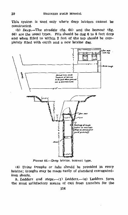
39 ENGINEER FIELD MANUAL
This system is used only where deep latrines cannot beconstructed.
(b) Deep.-The straddle (fig. 65) and the boxseat (fig.66) are the usual types. Pits should be dug 6 to 8 feet deepand when filled to within 2 feet of the top should be com-pletely filled with earth and a new latrine dug.
Fntre 66.-Deep latrine, boxseat type.
(4) Urine troughs or tubs should be provided in everylatrine; troughs may be made easily of standard corrugated-iron sheets.
h. Ladders and steps-(1) Ladders.-(a) Ladders formthe most satisfactory means of exit from trenches for the
114

FIELD FORTIFICATIONS ' 39
purpose of attack. Permanent ladders 5 feet long and insufficient numbers for patrols are ordinarily fixed to the frontwall of a trench.
(b) In preparation for attack a large number of looseladders should be placed in the parallels of departure. Whenthe attack is about to start these may be supplemented bytaking up trench boards and using them as ladders afterknocking off alternate crosspieces.
(2) Steps-To Permit travel over surface of the groundat night, ladders, steps, or ramps should be provided alongthe communication trenches throughout the position. Steps
SECTION A SECTON
rt A ._S A PLANELEVATION
( Ladder. D Steps.
FIGoRE 67--Sortie ladder and steps.
may be cut into the earth and revetted. Figure 67 showssimple types of sortie ladders and steps.
i. Telephone lines.-(1) Erection, maintenance, and repairof telephone lines other than organizational wire are dutiesof the Signal Corps. In trenches the two methods of install-ing wire generally used are-
(a) Wire trenches constructed for this purpose.(b) Installation in regular fire and communication
trenches.
115

39 ' ENGINEER FIELD MANUIAL
(2) Wire trenches vary in size from 10 inches wide by 10inches deep to 36 inches wide by 30 inches deep, a usualsize being 18 inches wide at the bottom and 30 inches deep.These trenches for stringing field telephone wire are leftopen. They offer considerable protection from shell fireand render wires easily accessible for repair. They havethe disadvantage of offering an obstacle to friendly trafficand are easily visible to the enemy. The field wire maybe fastened to cross arms on short poles or the cross armsmay rest against or project into sides of the trench withoutpoles. Instead of using cross arms the wire may be fastenedto the sides of vertical poles. Field wire may be fasteneddirectly to these supports with wire or marline but it ispreferable to use insulators.
(3) When it is impracticable to construct wire trenches,field wire may be installed in fire or communication trenches.Ordinarily wire should be kept on the side of the trenchnearest the enemy and from 10 to 30 inches from thebottom of the trench. The field wire may be fastened to theside of a trench by-
(a) Stiff wire staples about 12 inches long driven into sideof trench.
(b) Insulators mounted on boards which are fastened tosides of trench by rods or staples.
(c) Insulators on wooden stakes driven into side of trench.(d) Insulators on posts driven into bottom of trench close
to the side.(e) Attaching wire to revetment posts either directly or on
insulators.(4) Lead covered cables are laid along the bottom of
specially dug trenches and the trench filled in. Such trenchesabout 8 feet deep effectively protect against most shell firebut involve a great deal of labor. Lead covered cables mayalso be laid in communication trenches from 2 to 3 feet belowthe bottom of the trench. As a temporary measure cablesmay be strung along sides of trenches.
116
FIELD FORTIFICATIONS
SECTION VI
OBSTACLES
*40. CLASIFICATION.-a. Obstacles are natural or artificial.(1) Examples of natural obstacles are mountain ranges,
streams, lakes, swamps, thick underbrush, and tropical jungle.(2) Artificial obstacles are either-(a) Fixed, examples being high, double-apron, and low wire
entanglements. abatis, and inundations or(b) Portable, examples being concertinas, chevaux-de-frise,
and gooseberries.b. From the tactical viewpoint obstacles are either tactical
or protective.(1) Tactical obstacles may be either natural or artificial,
and are required to break up the enemy's attack formationand hold him in areas which are covered by intense defensivefires, particularly of automatic weapons. For this reason theirlocation is usually determined by the defensive fires, especiallythe final protective line of machine guns.
(2) Protective obstacles are usually artificial and preventthe enemy from delivering a surprise assault from areas closeto a position. They must be near enough for adequate sur-veillance by day or night and far enough away to preventthe enemy from lying beyond the obstacle and bombing theposition with hand grenades, Thus they should be between30 and 100 yards from the trenches. Skillful location maypermit an obstacle to serve both tactical and protectivemissions.
c. Obstacles may also be classified with respect to what theyare expected to stop, as against foot troops, horse cavalry, andtrack-laying and wheeled vehicles. Obstacles against trackand wheeled vehicles are covered in FM 5-30. This sectiondeals principally with obstacles against foot troops and horsecavalry.
· 41. BASIS or LOcATION, DESIGN, AND CONSTRUCTION.-a.Cover throughout by fire of the defense.
b. Protective obstacles under observation at all times.c. Deny enemy ground which might offer him shelter.d. Concealed by taking advantage of natural irregularities
of ground and natural growth.
117
40-41

ENGINEER FIELD MANUAL
e. Provide for all around protection.f. Avoid regular, geometric lay-out that discloses location
of position and its elements.g. Use belts from 4 to 10 yards wide separated by intervals
of from 15 to 40 yards.h. Barbed wire entanglements are the most nearly ideal
of the artificial obstacles.
* 42. BARBED WIRE.-a. Materials.-((1) Barbed wire is obtain-able in various styles. The standard is the familiar two-wiretype of No. 12, A. S. & W. gage wire with four-point barbs,spaced approximately 4 inches apart. The length on a com-mercial reel as shipped from the factory is about 420 yards,and the weight of a full reel about 100 pounds plus weight ofthe reel, about 5 pounds. Reels of about one-half the fore-going size are also obtainable, and are desirable. Hand bob-bins are usually made up at the rear from the large sizereels, contain 30 yards of wire, and weigh from 8 to 9 poundseach. They are always used when constructing entanglements.
(2) To make bobbins, secure 1-inch round or square sticksapproximately 2½/2 feet long. When necessary round off theends to facilitate handling. It is desirable to drive eight-penny or tenpenny nails through the stick about 8 inchesfrom each end. This type of bobbin stick and an alternativetype, which takes more time and material to make but iseasier to handle, are shown in figure 68. Improvise trestles,pass a pick handle, piece of pipe, or other suitable articlethrough the reel, and place in the trestle so that the wire maybe unreeled from the bottom (see fig. 68). Two men work atmaking bobbins, one at the bobbin and one at the reel, alter-nating duties from time to time. The bobbin man fastensthe end of the wire to one of the nails in a bobbin stick anddraws the wire out over a measured distance of 30 yards. Theman at the reel controls movement of the reel by hand or bybraking with a stick. The bobbin man grasps the stick at thecenter with both hands and keeps his hands in this positionwhile making the bobbin. Maintaining a constant strain onthe wire, he moves toward the reel at the same time windingthe wire on the bobbin by overhand movements so that thewire is passed alternately over and around first one end ofthe stick, then the other, coming to rest on the nails as shown
118
41-42

FIELD FORTIFICATIONS
in figure 68. When the 30-yard length of wire, about 45 turnson the bobbin, has been wound the wire is cut and the freeend marked with white rag or tape and secured. The result
I-I 12 ROUND OR SQUARET -I A hll-,CROSSPIECES NAILED OR WIREDa`'\
I \
tt- C· 12-2 ROUND OR SQ
1'i - -~ 40-46"
FREE END MARKED WITH WHITE
& ~ ~ 7 V~ W-, - ~~-
FGormE 68.-Making bobbins.
is a compact bobbin of light weight. One man can easily carryfour such bobbins, two in each hand, or six on a stick on hisshoulder.
119
42
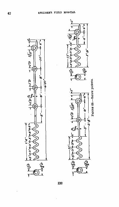
42 ZNOINUER YIELD MANUAL
49
"' 1
A~~~~
C,
N~ -t
C)
1a~~~~~~~~~~~~~~~~~0
~~ b,~~~
*2ml)~~~~~~~~(
to \
-I
120
I
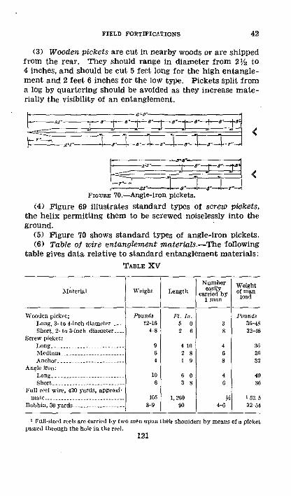
FIELD FORTIFICATIONS 42
(3) Wooden pickets are cut in nearby woods or are shippedfrom the rear. They should range in diameter from 21/2 to4 inches, and should be cut 5 feet long for the high entangle-ment and 2 feet 6 inches for the low type. Pickets split froma log by quartering should be avoided as they increase mate-rially the visibility of an entanglement.
FIGr 70I.--Angle-iron pickets.
(4) Figure 69 illustrates standard types of screw pickets,the helix permitting them to be screwed noiselessly into theground.
(5) Figure 70 shows standard types of angle-iron pickets.(6) Table of wire entanglement materials.-The following
table gives data relative to standard entanglement materials:
TABLE XV
Number WeightMaterial Weight Length eaY omcarried by ld
1 man
Wooden picket: Pounds . Ill. PondsLong, 3- to 4-inch diameter . 12-16 5 0 3 3-458Short, 2- to 3-inch diameter, 4 8 2 6 8 32-8
Screw picket:Long -......------- 9 4 10 4 36Mediu........... 6 2 8 6 36Anchor ................. I 9 8 32
Angle iron:Long --- --- --......... -- 10 6 0 4 40Short ........... 6 3 8 6 36
Full reel wire, 420 yards, approxi-rmatc ....................- 105 1,260 o¼ ' 52.5
Bobbin, 30 yards ......- - - 8-9 90 4 32 54
I Full-sized reels are carried by two men upon their shoulders by means of a picketpassed through the hole in tile reel.
121

ENGINEER FIELD MANUAL
b. Types of entanglements-The following obstacles maybe considered standard and methods for their constructionare outlined:
(1) High wire entanglement,(2) Double-apron fence.(3) Low wire entanglement.(4) Belts of barbed wire or concertinas.(5) Portable wire obstacles..c. Wire entanglement drills.--(1) General.-The following
remarks and precautions are applicable to all entanglementdrills.
(a) The line of stakes toward the enemy for high wire andthe center line for double-apron and low wire should betraced and marked in the manner described for trenches.Use of tracing tape is highly desirable for night work inpresence of the enemy.
(b) The men are given numbers in the order in which theyfirst proceed to work, each having definite, limited tasks.They start at intervals so that men doing different tasks willnot be bunched, exposed to fire, or interfere with each other.One row of pickets is set by pacing. The others are placedby eye, using the paced row as a guide. The elements nearestthe enemy should be placed first, and work continued to therear.
(c) Pickets should be carried under the left arm and placedon the ground with the right hand so that end of the screwor point of the picket faces the enemy, indicating the spotat which the picket is to be erected. For carrying, all bundlesof screw and iron pickets should be wrapped with a sandbagand secured in at least two places by a turn of plain wirewith the ends twisted together. Enough end to this wire mustalways be left so that it can be untwisted by hand withoutpliers. Bundles of long wooden pickets should be tied to-gether in at least two places with a plain wire. Short woodenpickets are carried best in sandbags, a suitable number ineach bag. Two bags are tied together and slung over theshoulder. Screw pickets must be screwed in so that the eyesare parallel to the length of the entanglement, and the eyepoints in the direction from which the men are working, thatis, toward the starting point. Compliance with this rule fa-
122
42

FIELD FORTIFICATIONS
cilitates placing wires. Wooden pickets used as hold-fasts(anchors) should be driven in approximately at right anglesto the stay wire to be attached to them, but screw anchoragepickets must be placed in prolongation of this stay wire.
(d) In running out barbed wire two men work together;one man walks out with the bobbin, unwinding as he goes,and the other stretches the wire and fastens it to the pickets.
(e) Men fastening the wires must always work facing theenemy.
(f) The carrying parties indicated in the drills can carryat one trip all the material required for 50 yards of entangle-ment. If a round trip to the dump requires more time thanconstruction of 50 yards of obstacle, strength of the carryingparty must be increased accordingly.
(2) Fastening wire to pickets.-(a) To fasten wire in topeye of screw picket (see fig. 71 (); pull the fixed wire (theone leading toward the starting point) taut and slip thewire up into the eye, turn the running end up over theeye, thus threading the wire in the eye. Then take a turnwith the running end over the standing end and aroundthe picket below the eye.
(b) To fasten the wire in a lower eye of a screw picketwhen there is already a wire in the top eye-
1. Pull the fixed end taut and slip the wire up into theeye. Then take a bight on the running end, passit around the picket above the eye, and take aturn with the bight on the running end (see fig.71 ®).
2. If one eye is on the opposite side of the pickets fromthe others, the wire must be forced down into theeye, and the bight on the running end passedaround the picket under the eye (see fig. 71 ().
(c) The foregoing rules ((a) and (b) above) apply which-ever way the wiremen are working, from right to left or leftto right, and if carried out the wire will be fixed firmly in theeye and cannot slip up or down the picket. Also, if one bayis cut the wire in the bays on either side remains taut anddoes not slip through the eyes.
(d) Wires are fastened to wooden pickets as shown infigure 72.
123
42

ENGINEER FIELD MANUAL
(D At top of picket.
0 Intermediate eye, %wire underneath.
0 Intermediate eye, wire on top.
FIGURE 1.-Proper method of fastening wire to screw pickets. .
124
42

FIELD FORTIFICATIONS
(e) To fix one wire to another a short length of smoothwire may be used or the two wires may be twisted togetherby means of a rack stick as shown in figure 73. This is thebetter method and is known as "windlassing." Each mem-ber of a wiring party is equipped with a rack or windlassstick.
(3) High wire.-(a) This entanglement consists of a se-ries of fences made of standard long pickets either wood,screw, or angle iron, spaced 10 feet apart. A sufficientlyclose approximation to the distance is 4 paces of an average
FlGmuR 72.-Proper method of fastening wire to wooden pickets.
man. The spacing in depth between successive rows is thesame; thus five rows of pickets give an entanglement 40feet in depth. In each row the pickets are placed oppositethe center of the intervals between pickets of the adjacentrows. This arrangement is shown in figure 74.
(b) On each fence or row of pickets there is a bottomhorizontal wire about 6 inches above the ground and a tophorizontal wire at or near the top of the pickets; also, ineach bay there are two diagonals. This system of top andbottom horizontals and diagonals also runs in a zigzag
262375--40-9
42
125

42 ENGINEER FIELD MANUAL
APOiH WVit
XFaOM LAST ASTErKI
TO AOBPIN -
x APaoH WIl.'
FPoM LAS
THG
T fASTElNG
TO
PFROM LAST PASTEnlNG
To BC
APMoN WIRtFROM LAST FASTENING
Q KC STICK
TO B°BOt %
'ALTtRNAT[ METHODFinour 73.-Method of fastening two wires together by
"windlassing."
126

FIELD FORTIFICATIONS
direction between rows of pickets, giving a series of tri-angular cells. All wires are strung in the order and man-ner shown in figure 74.
(c) This type of entanglement may be constructed withtwo rows of pickets, giving a complete unit. For more im-portant obstacles it is constructed in greater widths, fiverows of pickets generally being employed and being con-sidered a full belt. The full width of the entanglementneed not be built as the first operation; two or three rows ofpickets may be driven and wired across the front to becovered to develop the defensive value of the position atonce. Inclined anchorage pickets may be placed oppositeeach picket of the outside row and at a distance of about5 feet from the picket. Guy wires are attached to these,running to the head of the main pickets. This practice issometimes varied by placing the anchor pickets opposite thecenter of intervals between main pickets and guying di-agonally in both directions. At least two strands of wireshould be used on each guy, preferably barbed wire as usedin the entanglement itself.
(d) In case sufficient barbed wire is not available for thewhole entanglement, the most efficient utilization of it wouldbe for the top and bottom fence wires as it is these that thebody encounters whether the soldier attempts to go over orunder the obstacle.
(e) Drill for erecting high wire entanglement.
TABLE XVI.--50 yards high wire entanglement (two rows ofstakes)
127
Materials Wiring party Carrying party
8 bundles (total of 32) 1 noncommissioned offier 1 noncom missionedlong pickets. (carries ;pliers) officer.
32 30-yard bobbins 16 men (each carries a rack 18 men.barbed wire. stick).
I man, carrier.
I
42

42 ENGINEER FIELD MANUAL
TABLE XVI-50 yards high wire entanglement (two rows ofstakes)
Second task I Third task
Leads party to Paces front panel and indicates location ofhead of work. pickets; supervises work.
Place pickets of front String bottom hori-panel. zontal wire, zig-
zag panel.
3........ -out one bundle4.. pickets.
Each man carriesout three bhob-bins barbedwire.
Place pickets ofrear panel.
Screw in pickets oflfront panell.
Screw in pickets rearpanel.
String bottom hori-zontal wire, frontpanel.
String first diag-onal wire, zigzagpanel.
String second diag-onal wire, zig-rag panel.
String top horizon-tal wire, igziagpanel.
String bottom hori-zontal wire, rearpanel.
String first diagonal String first diago-wire, front panel. nalwire. rearpanel.
String second diag- String second diag-onal front panel. onal wire, rear
panel.
String top horiron-tat front panel.
Carry out 5 bobbinsbarbed wire.
String top horizon-tal wire, rearpanel.
128
First taskXos.
Noncomnmis-slonedofficer.
1 ......2 -- -
5 ------6 .
S .
10. -.
11
13- -14.
NOTl. Numbers I to 4 place pickets lightly in ground. In stringing, odd num.hers run out bobbins, een nunmbers fix a-ire to pickets.
__-

FIELD FORTIFICATIONS
_ _ _ _ _ _ _ _I C _ l ' oI 0I 4 PACES I
II Ip :I_-- ..... H9 :'. I a _ .
L_.3 _C C S O - Oi-
.7i , 1flOS IG R"
[,23 ETC GIVES ORDER OF STRINGING WIRE
tti
FGITRE 74.--High wire entanglement.
129
42

ENGINEER FIELD MANUAL
Each additional row of high wire entanglement
\'Tterial Wirilng party Carrying party
4 bundles (total of 16) long t nonommilsiolled ofil 1 nonormisrisloneedpickets. er. officer.
24 30-yard bobbins. 10 men, 2 men.
(4) Double-apron fence.-(a) The double-apron fence,4- and 2-pace, consists of a central row of long pickets spaced10 feet, or 4 paces, apart, upon which are strung four hori-zontal strands equally spaced from top to bottom. Parallelto and on each side of this row of pickets is placed a row ofanchorage pickets to which diagonally inclined wires formingthe apron are strung. The anchorage pickets are placedopposite the intervals, and 5 feet, or 2 paces, from the lineof the long pickets. Each of the two sets of diagonallyinclined wires carries three horizontal wires. This type ofentanglement is erected with great rapidity and resists de-struction by shell fire or bangalore torpedoes as well as anyother pattern. For very rapid work and to develop utilityof the barrier at once, the back apron is sometimes omitted.If sufficient barbed wire is not available, smooth wire may beused for the rear apron and if necessary for the diagonalwire of the front apron. Value of the entanglement lieschiefly in the front apron which should never be omitted.All wiring is done from front to rear, the diagonals in thefront apron being placed first. Three horizontal wires areplaced on the sloping apron and windlassed to the diagonalwires. The four horizontal wires of the central fence arenext strung, following which the diagonals and apron wiresof the rear apron are placed successively (see fig. 75).
(b) This entanglement is economical in labor and mate-rial and can be developed into a broad barrier by constructionof successive bands. The space between bands can be filledwith portable obstacles or loose wire in the form of spirals.As in the construction of the high wire type, the workingparties are covered by the first elements of wire placed, andthey work behind it toward their own lines.
130
42

FIELD FORTIFICATIONS
a14
1,2.3, ETC. GIVES ORDER
OF STRINGING WIRESZ PACES -2 PACES|
GUlovn 75.--Double-apron fence, 4- and 2-pace.
131
42

42 ENGINEER FIELD MANUAL
w
Q)
Id
0
0
Z.-e
,0
dd
In
w
0.4
p
132

FIELD FORTIFICATIONS
d e d· s: de ;e d .
-b ·= 8 ' a ~ ; 8 d d ·O m B Br X oW
Bg pd E d i d ;}° t I S
CC o. 00 0 oU
.o ~ ~ i 4 a C
g a a; a .Pg ) CC* Po
0.4L CC.)*) O 0
~~~a a
" E B1
Pe pl go
00 .t o .. , c~ OC) -L
COCA 00 ~n
1·- ~ ~ ~ ~ ~ 0
0.4" g "N e j o0R Bd~~~k ~p$~ C Ce
0 -, 0+C ,Cg00 ~ ~ ~ 0 0 -
.,; C) I
133
42
i .XC
I.a

42 ENGINEER FIELD MANUAL
(d) The double-apron fence, 6- and 3-pace (fig. 76), isexactly similar to the 4- and 2-pace type except that thedistance between long pickets is 6 paces instead of 4 and theanchor pickets are placed 3 paces instead of 2 from thecenter line of the obstacle. This results in a wider obstaclebut one that is probably not as strong as the 4- and 2-pacetype. As may be seen from table XXI, the number andweight of long and anchor pickets is about 30 percent less forthe 6- and 3-pace type and there is no increase in amount ofwire required. The wiring party is reduced by one man andhence the man-hours by '/2 man-hour for 50 yards of entan-glement. Also drill for erection of the 6- and 3-pace fenceis simpler, This reduction in amount and weight of materialand in man-hours required is a very important considerationin many situations. However the 6- and 3-pace fence hasnot had the benefit of actual war experience as has the4- and 2-pace.
134
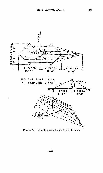
FIELD FORTIFICATIONS
WIRE
6 PACES 6 PACES 6 PACES15' O" 15'0 15 i 0"
t,3 ETC. GIVES ORDERDF STRINGING WIRES II
I_ _e3 PACES - 3 PA
FIouRE 76-Double-apron fence, 6- and S-pace.
135
IE
42

42 ENGINEER FIELD MANUAL
e cc
iE
C)a _
" .B _ _ S
o E e F i r
_ C,
I ZL -E
o - ;
E H : .E
2~~ E
C) ~
CtV
0
~H S CL
.4- ~ ~ ~ ~ ~ ~ ~ ·-
136

FIELD FORTIFICATIONS
c
2
C
C
a
I O-. S
W4
137
42

42 ENGINEER FIELD MANUAL
(5) Low wire.-(a) The low entanglement (fig. 77) con-sists of a double-apron with the fence, except the top wire,omitted. Medium pickets are used, preferably of the screwtype, spacing and arrangement being the same as for thedouble-apron fence. The wire forming the inclined diagonalstoward the enemy is strung first. Across the diagonals arethen laid the three horizontal wires in the order indicatedin figure 77. A horizontal wire is next strung along the topsof the pickets. The wire forming the rear diagonals is thenstrung, followed by the three horizontal wires which it sup-ports in the order indicated in the figure. Horizontal wiresare windlassed to inclined diagonals at points of contact.
(b) The chief advantages of the low wire type are its econ-omy of material and labor and its low visibility with respectboth to direct and terrestrial observation and to aerial pho-tography. It is preferably built in long grass where it becomesalmost entirely invisible. Its chief disadvantage is the obviousone that a man with reasonable ability can pick his waythrough it without much trouble. As a surprise entanglementit is unquestionably effective.
(c) Low wire entanglement of either 6- and 3-pace or 4-and 2-pace types may be constructed. Advantages and dis-advantages of the two types of double-apron wire (see (4)(d) above) apply to low wire entanglements. Figure 77 andtable XIX give details and drill for the 6- and 3-pace type.The 4- and 2-pace type is exactly similar except for substitu-tion of 4 and 2 paces for the 6 and 3 paces in laying out thewire and for the changes noted in the drill table XIX.
138
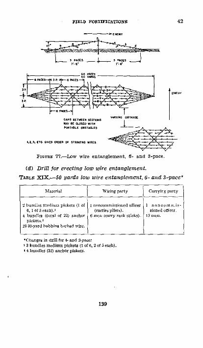
FIELD FORTIFICATIONS
- * EemY
?' . ¢
1.2,3. ETO GIVES OADSE OF S$RINiiN WIsRE
FGuRa 77.-Low wire entanglement, 6- and 3-pace.
(d) Drill for erecting low wire entanglement.
TABLE XIX.-50 yards low wire entanglement, 6- and 3-pace*
Materal Wiring party Carrying party
2bundles tnedium pickets (1 of 1 noncommissioned officer 1 n o Co 3i1 is -6, of each).' (carries pliers) sined officer.
4 bundles (total of 22) anchor 6 men cary rack sticks). 13 nee.plickets.2
20 30-yard bobbins barbed wire.
Cb Fanges in dril for 4-and 2-pace:3 bundles medium pickets (I of 6, 2 of 5 each).
O 4 bundles (32) anchor pickets.
139
42

42 ENGINEER FIELD MANUAL
TABLE XIX.-50 yards low wire entanglement, 6- and 3-Pace*-Continued.
First task Seinf th task Fit task Sixth t'sk
NoIcoImmissioned officer s pac(s oill and indicates to Nos. I and 2 location for theirickets. Supervises work.
I Carris out Carries outI hlndle I hundle1 bcundle bundile L out String anot String and String andmedium. medium and screw faslen windlass windlahspickets. pickets- in center front dag- top huri- top hori-
2 Carries out Carries out line of onal wire rontal wire zontal Wire1 trundle I bundle pikeits front apront rear apron
anchor anchorplickeus rickets
3 Carries out Carries outI bundle 1 bundle Lay out String and String and String andanchor ancor and sercrw windlass fasten hor. windlasspickets tickets in outer trip wire, izontal second hor-
anchor front apron wire, cen. irontal4 Carries out Carries out pickets ter line wire, rear
4 bobbins 4 bobbins apronharhed wire barbed wire
5 Carries out Carries out4 bobbins 2 bobbins La. ollt String and String and String and
barbed wire barbed wire and screw windlass Lasten rear windlassin inner second hor diagonal trip wire.
li Carries out Carries out anchor izontal aire rear apron4 bobbins 2 bobbins pickets ire, front
barbed wire barbed wire apron
Carries out I bundle mrediun pickets. Paces off and indicates to Nos. 1 and 2location for their pickets. Lays out own pickets. Supervises work.
Nots-No. 3 places picket at head of work. No. 5 places anchor picket at foot ofwork. Diagonal wire of rear apron and horizontal w-ire on center line of pickets arenot carried down to end anchor pickets. Low-wire entangements are slow to erectat night, owing to the difficulty of seeing the pickets.
140

FIELD FORTIFICATIONS
(6) Four-strand fence.-Under press of time or shortageof men or materials, a less effective type of entanglement canbe erected. For such purpose the four-strand fence may beused. This is the central fence of the double-apron fenceentanglement (see fig. 80). This can later be elaboratedinto the double-apron fence by addition of the aprons. Thefour-strand fence can be erected by an 8-man wiring partyand an 8-man carrying party at the rate of 50 yards in 15minutes, day work, with a carry of not more than 400yards. For longer or shorter carries, the carrying partyshould be increased or decreased proportionately. This typeof wire is usually employed as the protective wire around thedefense areas.
(7) Barbed wire concertina.-(a) This type of obstacleis prepared in advance and in the field needs only to beopened out, supported on a wire strung between posts, andstapled to the ground.
(b) Draw on the ground a circle 4 feet in diameter. Placenine posts, an odd number is essential, equally distant, ap-proximately 17 inches apart around this circle and drivethem, leaving a height of 5 feet above ground. Angle-ironpickets are much easier to work with than wooden ones.One 100-yard coil of barbed wire is required per concertina,with short lengths of plain wire for fastening. The unitparty is three men. No. 1 works inside the framework, Nos.2 and 3 run out the coil, No. 2 helping No. I if necessary(see fig, 78).
(c) Average time per concertina is 20 minutes. Take twocomplete turns around the nine posts with No. 10 plain wireor four turns with No. 16 wire, and bind these turns togetherat each interval between posts so as to form a secure endring for pulling the concertina out. Fasten the end of thebarbed wire to the plain wire and take 24 turns with it aroundthe posts in a spiral form, binding two consecutive turnstogether at every other interval, using No. 16 plain wire forbinders. Make two turns with plain wire and make fast.It assists to have a nonagonal-shaped framework to fit insidethe top of the pickets so as to keep them properly spread out.It is easily removed when the concertina is finished.
262375'140 10
42
141

42 ENGINEER FIELD MANUAL
(d) The easiest method of carrying is to wire a slat toeach face of the closed roll, the slats parallel to each other.The points 90' from the slat fastenings are then lightly tiedwith tape. The concertina can easily be carried by two men,or with reasonable ease by one man if in the open.
(Element collapsed ®Method of making concertinaand prepared for element with either plain orcarrying. barbed wire.
®Concertina extended.IPIGURE 78.-Concertina.
(8) Concertina.-(a) Concertinas open out to a length ofabout 20 feet and are formed into an entanglement by tyingend to end. The elements are supported between posts spaced20 feet apart and carrying a taut top horizontal wire to whichthe elements are secured. Each coil should also be stapledin at least three places to the ground. The entanglement
142

FIELD FORTIFICATIONS
may be thickened in depth as desired by adding successivelines. Figure 79 shows the manner in which concertinaelements are arranged to form an entanglement.
PA CES2o' 0'
TAUT TOP HORIZONAL WIE BARBEDI
STAPLEfS iNTO1 RO.D
CONCERTINA EXTENDEDFicuRE 79.-Double-belt concertina entanglement.
(b) The entanglement has the advantages of low visibility,rapidity and ease of construction once the elements areprepared, and difficulty of destruction by artillery owing toits strength and resiliency. Being stapled to the ground itis difficult to pass, and in double lines with a top horizontalwire it forms an exceedingly efficient barrier.
(c) Drill for erecting concertina entanglement.
TABLE XX.-50 yards double-belt concertina
slaterials
4 bundlcs (total of i'i) longpickets.
4 anIchor pickets. ...14 coils concertin,.2 50-yard coils barbed 'irr.
o0 ;s ire staples.248 inch pieces No. 16 plain
ire.
Wiring party Carrying party
I nnellcinlissionel oEfcerr I noncomnmis-(carries pliers). sitned officer.
10 nlen (Nos. I and 2 each 20 men.carry 12 pieces plain wire;9 and 10 each carry 15staples; all carry racksticks).
143
42

42 ENGINEER FIELD MANUAL
TABLE XX-50-yards double-belt concertina-Continued
Nos.I Firsttask ISecondt ask Third tak I Fourth task Fifth task
Noncommissioned offeer carries cut 4 anchor pickets. Paces ill distances andlocates pickets. Supervises work.
Open out andplace infront lineof pickets Iconcertina.
Opcn out andplace infront linceof pickets Iconecrtina.
Open out andplace infront lineof pickets 2coneertinas
Open out andplace infront lineof pickets 2concertinas.
Wire coils together in bothbelts, No. 1 working onenemy side, No. 2 opposite.
Open out and P un horizon-place in tel wiresecond line along topof pickets I of pickets,conecrtins. first row
Easten wireto pickets.
Open out and W in I as splace in coils tosecond line wires at aof pickets 2 points hc-concertinas. twcen each
2 pickets.
Run horizon-tal wirealong topof pickets,second row.
Openoutand Fasten wireplace in to pickets.second lineof pickets 2concertinas. V in d I a ss
coils towire at 3points be-tween each2 pickets.
I
Each laysout andscrews in4 longpickets.
Lays out andicrews in4 anchorpickets.
Carry out Iconcertinacoil andcut thetoales.
Carry out 4long pick-ets eath.
Carries outI conecr-tins a in dcuts tape.
Carry out 2conwcrtinasand cut tietapes.
P
_
144

FIELD FORTIFICATIONS 42
TABLE XX.-50-yards double-belt Concertina-Continued
Nos. First tasx Second task Third task Folart task Fifth task
9 Carry out I Open out nd Open out nd Stapl downcoil barb- place in place in both belts.ed wire. front line second line
10 ofl ticket s I of pickets 2_oncertina oncert ins.
bNOTEr-Nos. 6, 7, S,9, anld 10 place cois in inerl' als belateen liike in asksNos. 1 and 2.
(9) Table XXI, below, is a summary of material and labolrequired for 1,000 yards of various single-belt entanglements.
TABLE XXI.-Summary of material and labor required for1,000 yards of single-belt entanglement
Pickets Barbed wire Pirn .
wire . .
4- sal 2-p sce 3YG .r~o 37 52P 3, 883 o3
Type of tnrangle- =z
raent (2 c- z :
dess. Lh Lb Ls.uigh wire-....... 0 -..2- 60 2 6 q ]640 '4,20 -.. 9 12
Double apron:4- and 2-pdae ..... 320 . 40 37 520 3 885 .8...1 5 100- and3-pac_ 220 _ 40 37 520 35885 ... 41 8
Low wire --......... 220 440 29 400 3. t5. . . 51 6.25Concertina (2 cylin-
ders side by side) n _ 302 ...... 75 --.. 7875 700 9I0 100 a 1 I2Four-strand wire
fence (protectivewire around defense
areas) ......-... 1 300 I ItI 141._155 -1 -.-- 2 4
I Specially skilled crews of picked men undisturbed have e-reted entanglementsin less than 3 of times stated in this column. I For front athorge if used,
Pilus 3 if front anchorages are used. 1 Plus 315 if front anchorages are used., Erection of entanglement only; does not include making bobbins or canrying
party. Mlan-hours for carrying party varies, depending on distance and rate ofcarrying.
I Erection of fence only. Does ino inetilliude nikig of c(lindters or carrying party.
145

42 ENGINEER FIELD MANUZAL
(10) Spider wire.-Figure 80 shows a form of entangle-ment using four-strand fences identical in design to thecentral portion of the double-apron fence. Obviously theycan be developed into single- or double-apron fences whendesired. This open irregular crisscross grouping of fences isknown as spider wire entanglement. It is very useful forwiring in defense areas. The fences using wooden or angle-iron pickets can be made up in portable lengths rolled up,
4 PACES 4 PACES 4 OCCUPIEE D TRENCGL io' - ' UNO NCUPIED
A C 'U~ouar lc VWEPONA.A - ..T....
ELEVATION OF FENCE
FraozE BO.Spider wire entanglement showing use of four-strandfences as obstacles around defense area without disclosing occupiedportions of trenches.
carried to front positions, and there quickly set up by drivingthe pickets into the ground as the fence is unrolled.
d. Estimating quantity of entanglement.-(1) To estimateproperly tonnage of material (pickets, wire, etc.) for a defen-sive position, it is necessary to know approximately howmuch material is required to cover a battalion area witha reasonable amount of wire obstacle. The weight of pro-
146
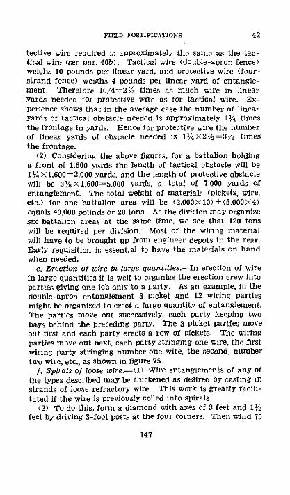
FIELD FORTIFICATIONS
tective wire required is approximately the same as the tac-tical wire (see par. 40b). Tactical wire (double-apron fence)weighs 10 pounds per linear yard, and protective wire (four-strand fence) weighs 4 pounds per linear yard of entangle-ment. Therefore 10/4=2V/2 times as much wire in linearyards needed for protective wire as for tactical wire. Ex-perience shows that in the average case the number of linearyards of tactical obstacle needed is approximately I¼1 timesthe frontage in yards. Hence for protective wire the numberof linear yards of obstacle needed is 1/4X2'/z=3/s timesthe frontage.
(2) Considering the above figures, for a battalion holdinga front of 1,600 yards the length of tactical obstacle will be1 X 1,600=2,000 yards, and the length of protective obstaclewill be 31/3 X1,600=5,000 yards, a total of 7,000 yards ofentanglement. The total weight of materials (pickets, wire,etc.) for one battalion area will be (2,000X10) +(5,000X4)equals 40,000 pounds or 20 tons. As the division may organizesix battalion areas at the same time, we see that 120 tonswill be required per division. Most of the wiring materialwill have to be brought up from engineer depots in the rear.Early requisition is essential to have the materials on handwhen needed.
e. Erection of wire in large quantities.-In erection of wirein large quantities it is well to organize the erection crew intoparties giving one job only to a party. As an example, in thedouble-apron entanglement 3 picket and 12 wiring partiesmight be organized to erect a large quantity of entanglement.The parties move out successively, each party keeping twobays behind the preceding party. The 3 picket parties moveout first and each party erects a row of pickets. The wiringparties move out next, each party stringing one wire, the firstwiring party stringing number one wire, the second, numbertwo wire, etc., as shown in figure 75.
j. Spirals of loose wire.--() Wire entanglements of any ofthe types described may be thickened as desired by casting instrands of loose refractory wire. This work is greatly facili-tated if the wire is previously coiled into spirals.
(2) To do this, form a diamond with axes of 3 feet and 1Ifeet by driving 3-foot posts at the four corners. Then wind 75
147
42

42 ENGINEER FIELD MANUAL
yards of barbed wire around this framework from the bottom,gradually working up the stakes in a spiral. Finally take thespiral off the stakes and tie it together in four places with tape.It then can be carried easily to place where it is to be used. Ifspirals are needed in large quantities a winch may be impro-vised and used to advantage.
g. Gaps in wire.-(1) It is necessary that openings in ob-stacles about a defensive position exist at frequent intervalsto permit passage of our own patrols, working parties, andassault columns. These gaps are generally formed by cuttingzigzag passages through the wire after its construction iscompleted. By echeloning gaps in successive belts, it is pos-sible to render them invisible to direct observation. In thecase of operations involving a general advance it is necessaryto cut many such passages in the wire, but these are preparedthe night preceding the attack so that the preparations maynot be observed by enemy observers. In order to deny passagethrough gaps to the enemy, the openings are normally closedby portable obstacles which can be removed readily for passageof friendly troops.
(2) Enemy entanglements may be breached by artilleryconcentrations, by tanks, by specially trained men using wirecutters or by heavy charges of high explosives extendingcontinuously through the belt to be breached (see FM 5-25).
h. Knife rest or cheval-de-frise.-The knife rest consists ofa framework of wood or iron upon which is strung barbed wire.It is sometimes called a cheval-de-frise. The framework,if the iron type, may be made collapsible and hence easierto transport, as well as being more difficult to see and strongerthan the wooden type. In shape, the framework of the kniferest is of the same appearance as a common sawbuck. Figure81 shows its construction. Chevaux-de-frise (plural ofcheval-de-frise) are frequently used to stop temporary gapsin entanglements, to barricade trenches leading toward theenemy, to barricade roads and streets, and may be used as anunderwater obstacle in beach defense.
i. Gooseberry and hedgehog.-() The gooseberry consistsof barbed wire balls connected by spirals of the same material.It is used principally to block trenches. For this purposethe balls should be made with a diameter slightly greater
148
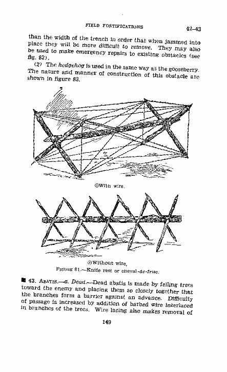
FIELD FORTIFICATIONS 42-43
than the width of the trench in order that when jammed intoplace they will be more difficult to remove. They may alsobe used to make emergency repairs to existing obstacles (seefig. 82),
(2) The heldgehog is used in the same way as the gooseberry.The nature and manner of construction of this obstacle areshown in figure 83.
®Witn wire.
(Without wire.IGOmE 81.-Knife rest or cheval-de-frlse.
D 43. ABATIS.--a. Dead.-Dead abatis is made by felling treestoward the enemy and placing them so closely together thatthe branches form a barrier against an advance. Difficultyof passage is increased by addition of barbed wire interlacedin branches of the trees. Wire lacing also makes removal of
149

43 ENGINEER FIELD MANUAL
The fin;ssedGooseterrev Olt ndspirally withbarh)twlre, lstfened atpqints with smooth
oire.Connected to
another berry ya spiral coil.
arnd opened upforming a sphere rlO s around
the peSs, fastenecd
at two places withsmal smooth wire
FIcURE 82.-Gooseberry.
FiCGRE 83.-Hedgehog.
150
FIELD FORTIFICATIONS
the barrier more difficult. This type of barrier is highly effi-cient as a rapid means of blocking a road lined with trees.In the case of a road between two rows of trees, the trees onboth sides are so felled that their tops interlock, making thebarrier as dense as possible. Trees are preferably only par-tially cut through when felled so that their removal may bemore difficult. Dead abatis has the disadvantages of beingconspicuous and inflammable when dry. For these reasonsit is often worth while to go to the greater labor of buildinglive abatis for defenses in a wood.
b. Live.-(1) In the organization of woods where the growthis suitable, it is possible to form a barrier by bending down,interlacing, and tying the easily bent saplings and lowerbranches of adjacent trees in such a way that the obstacle isinvisible to both ground and air observers (see fig. 84). Thistype of barrier is usually constructed in extended depth andis practically impassable to advancing Infantry unless cir-cumstances are such that trench knives or axes can be used.
t2) It is sometimes the practice in connection with use oflive abatis to augment its impassability by addition of a num-ber of plain or barbed wires strung from sapling to sapling ortree to tree. Use of pickets in this situation should be avoidedas they increase visibility of the barrier.
(3) In the organization of fairly dense woods abatis is notalways continuous; gaps are left at points which would nat-urally be the avenue of approach of advancing elements.These lanes of access are directed toward lines of supple-mentary barriers of double-apron or high wire entanglement,there being definite lanes cut through the woods along theenemy side of these barriers, and bounded by them and theabatis. These lanes are under fire from well-placed flankingweapons and are under good observation, The object of thistype of organization is to herd the enemy into zones fromwhich he cannot easily find an exit and which are swept byfire of automatic weapons.
(4) Lanes should not be too wide as they then become vis-ible from the air. It is possible in fairly dense woods to clearlanes 6 to 20 feet wide and to bring together the branchesoverhead, thus concealing their position.
151
43

44 ENGINEER FIELD MANUAL
t 44. IJuNnAnoNs.-Inundations form serious obstacles tothe attacker. They also may seriously limit counterattacksand this must be kept in mind before deciding to createinundations. They are created by building dams at suitablepoints. An extensive survey is frequently a necessary pre-
DDead abatis protecting hasty trench in woods.
( Dead abatis blocking road with live abatis on its flank.
FIGUE 84.-Abatis.
liminary step to determine the area and depth to be inun-dated and height and best location of the dam. However,these data can often be obtained from civil officials andagencies in the vicinity. In a stream with a firm bottom itrequires at least 4 feet of water to be a serious obstacle
152
IIAM�-�C-'� , I

FIELD FORTIFICATIONS
to infantry and 6 feet as a minimum should be sought. Ifthe bottom is soft or if the inundation is combined withother obstacles, a lesser depth suffices. Barbed wire entangle-ments prepared in advance, trees cut 1 to 2 feet below waterlevel, and post or rail obstacles are examples which wheninundated form most formidable obstacles. Inundations aremore difficult to cross when ditches are cut chequerwisethrough the ground to be inundated and deep pits dug beforedamming up the stream. Use of explosives for this purposeis discussed in paragraph 54, FM 5-25. Inundations are veryeffective obstacles against tanks or any form of vehicle.
* 45. UNDERWATER.-a. Underwater obstacles will be ex-tensively used in beach defense against landing operationsand in river line defense against river-crossing operations.The objects of beach and river line defense can be accom-plished best by defeat of attacking forces before they suc-ceed in placing any men on the beach or shore. Normally,defense of a beach or shore against an attempted landing inforce is provided by an organized infantry defense supportedby artillery and all auxiliary arms. This defense alone how-ever with all its fire power and land obstacles may notprevent enemy landings, especially at night or under heavyfog or smoke screens, unless obstacles are placed out beyondthe water's edge. This work is normally carried out byengineer troops and if not completely done by engineertroops the engineers should be called on for technical adviceand assistance in any beach or river line defense.
b. Obstacles in beach and riverline defense will consist ofany and all means available to delay the enemy's advance toto the shore, break up the orderly, methodical procedure ofhis landing operation, and hold him in the most adverse con-ditions under the maximum developed fire of the defense,These obstacles may include any or all of the followingbelts of-
(1) Small, sensitive contact mines in deep water but closeenough to the shore to be under protection of the shoredefense.
(2) Wire entanglement and other suitable obstacles underthe water to interfere with movement of enemy after disem-
153
44-45

4NGINEER FIELD MANUAL
barking from landing boats or to interfere with movementof landing boats.
(3) Wire on shore arranged to delay the enemy and holdhim under flanking fires of the defense.
e. (1) In general, the character of beaches and river linessuitable for landings may be divided into two classes, thosewhere the bottom drops away rapidly from the water's edge.and those having a gradually sloping bottom for a greater orlesser distance from the edge. Each type has its advantagesand disadvantages for the defense. The steep slope preventsdisembarkation until boats reach the beach, but it rendersplacing underwater obstacles more difficult. The gentle slopefacilitates placing obstacles, but it also allows the attackingtroops to disembark while still afloat.
(2) For those beaches and riverlines of the first type(steeply sloping bottom) provision should be made for stop-ping the landing boats and barges before they reach theshore. For this purpose the defense may utilize small, sen-sitive, contact mines anchored so as to be just below surfaceof the water; heavy logs anchored or tied to shore as floatingbooms either on the surface or just below the surface; andheavy cables or chains stretched between pilings. In all thesemethods the ideal solution would be to have all obstacles outof sight just below the surface, but a compromise must bemade with the amount of tide variation, and/or variationdue to flood conditions encountered. At the periods of high-est water level the obstructions should be near enough to thesurface to prevent the free passage of landing boats andbarges. This means that at low-water levels the obstructionsmay be in sight on surface of the water. However wheneverpossible provision should be made for adjusting obstaclessuch as log booms, cables, and chains to take care of fluctu-ations in the water level.
(3) For beaches and river lines of the second type (gradu-ally sloping bottom) the defense must not only guard againstthe boats reaching the beach, but must endeavor to stop thembefore they reach such depths that the personnel can debarkand wade ashore, and once wading has begun to render it asdifficult as possible. However, in addition to the obstaclesmentioned above, the shallow depth can be covered thor-
154
45

FIELD FORTIFICATIONS
oughly by underwater wire entanglements of all kinds an-chored or securely fastened to the bottom.
d. At certain places where water level variation is great,the situation shown in figure 85 may present itself, In thisfigure, the water level variation is assumed to be about 5 feet.Conceding that personnel can debark in 4 to 5 feet of waterand wade ashore, it is necessary to provide for two possiblestages of debarkation (at high and low water) and constructsufficient bands of obstacles to hold up landing at all stages.The figure shows a gradually sloping beach; a sharper slopewould decrease the amount of entanglement while a lesserslope might increase the number of bands. No definite rulecan be laid down.
e. (1) In figure 85, the obstacles shown at A and B can beconstructed during periods of low water. They may consist
F E HIGH WATER A
FroaE 85.--Underwater obstacles.
of any of the standard types of entanglements and obstaclesbut must be anchored more securely. Where heavy surfis encountered railroad rail sharpened and driven into thebeach is recommended for anchoring.
(2) The obstacles shown at C and D must be constructedon shore and then sunk in position. They may be eitherchevaux-de-frise made with angle-iron pickets, concertinasor any of the various barbed wire obstacles securely anchoredor picketed to the bottom, or a construction similar to thelow-wire entanglement. For the latter, a raft-like structuresimilar to the lobster pot shown in figure 86 is built, in orderto provide a means of weighting it down when it is sub-merged. All the elements in such a belt or band of obstaclesmust be securely anchored in position. Heavy anchors andsharpened railroad rail driven into the bottom are recom-
155
45

ENGINEER FIELD MANUAL
mended for this purpose but various expedients will have tobe adapted in the field to meet conditions.
(3) The heavy booms, cables, or chains shown at S andF (see fig. 85) tend to protect the entire installation. Ifbooms are used it will be necessary to anchor them from twodirections in order to avoid the possibility of their driftingover and damaging the wire entanglements at low water.Barbed wire may be used in connection with the booms,cables, or chains by stringing barbed wire obstacles on andbetween them.
As,- s /A
FlG-RE 86.-Lobster pot obstacle.
/. Underwater wire entanglements will require more wireand much more secure anchorages than those not con-structed under water, This is to prevent strong surfs orcurrents from carrying the entanglements away and so thatthe effect of enemy bombardment will be to tear the en-tanglements into nests of refractory wire rather thanclearing passageways.
g. Spaces must be left between anchored entanglementsso that enemy dragging operations will not clear a largearea at one time and also to provide channels for passageof friendly small boats for repair purposes. Concertinas will
156
45

FIELD FORTIFICATIONS
be found useful for such repair work. When desired, spacesbetween anchored entanglements can be closed effectivelyby heavily weighted spirals of refractory wire.. h. Other expedients that might be employed in beach orriverline defense are-
(1) Where shoreline is heavily wooded, fell trees into thewater's edge forming a thick impenetrable tangle (waterabatis).
(2) Spread gasoline or oil on the water and ignite it.This may be done in the case of rivers by dumping the gaso-line or oil on the water above the landing spot to be defendedor releasing barges or boats with drums of gasoline aboard,setting them afire and depending on them exploding amongthe attackers' landing boats.
(3) Boats containing charges of TNT with time fuse maybe released upstream and allowed to float downstream sotimed as to explode among the attackers' landing boats. Ifdrums of gasoline are also placed aboard such boats, a watersurface fire will result.
(4) Sunken hulks, floating mines, piles, nets, booms,chains, and demolished locks and bridges might be used invarious situations.
* 46. TANC.-For treatment of subject of tank, mechanized,and motorized obstacles see FM 5-30.
* 47. SuMmARY.-Maximum use should always be taken ofany natural obstacles which can be employed in the defenseplan. In some instances it may even be advisable to adjustthe entire plan of defense in order to take full advantage ofan effective natural obstacle. Barbed wire is the most effec-tive artificial obstacle (per ton of material) against person-nel on foot or horseback. Of the various types of barbedwire obstacles, the double-apron fence is the most effective,pound for pound, and can be erected quickly. It is thestandard tactical obstacle for use in organization of theground.
262375'--40-11
4547
157

ENGINEER FIELD MANUAL
SECTION VII
EMPLACEMENTS
* 48. INFANTRY WEAPoNS.-a. Necessity for protection.-Because of their relatively short ranges and advanced posi-tions in the combat zone, infantry weapons, including themachine gun, 37-mm antitank gun, 60-mm and 81-mm mor-tars, will often require emplacements for protection of thegun and crew. Heavy shellproof emplacements greatlyincrease effectiveness of these weapons, but because of thegreat amount of time and labor involved in their construc-tion they seldom will be found except in highly organizedpositions and even then only at key points. In mobile war-fare, open emplacements will be the general rule.
b. Automatic rifle.-Automatic rifles are habitually usedin trenches or fox holes. They do not require a special em-placement, though such an emplacement increases their effec-tiveness particularly in maintaining direction of fire at night,in smoke, or in a fog. Figure 87 shows typical positions forautomatic rifles. These positions should provide for-
(1) Piring recess in the parapet approximately of dimen-sions shown.
(2) Box for the rifle, 48 by 12 by 8 inches, with gas curtain.(3) Box for ammunition, 20 by 20 by 12 inches, with gas
curtain.c. Machine gun.-Machine-gun emplacements are classi-
fied as hasty and deliberate.(1) Hasty.-Due to the great fire power of machine guns
and their importance in battle, they must be effectively con-cealed from enemy ground and air observation, and as timepermits, effectively protected against effects of enemy fire.Concealment is of paramount importance but position of theweapon will be disclosed when it opens fire. Hence it isnecessary to provide additional protection and overheadcover. In open warfare, time will generally permit only hastyemplacements to be prepared and immunity from enemyfire is secured mainly through concealment. However, evenin open warfare the gun crew may secure some protectionfrom shell fire while not actually operating the gun by occu-pying concealed slit trenches constructed near the emplace-
158
48

FIELD FORTIFICATIONS 48
4~~~~~~~.
r'9 .
- 0
' t;
13
e 4
,. ~ ~~~~ 4,E, A e
159

48 ENGINEER FIELD MANUAL
ment. As time permits, splinterproof or light shellproof coverover the emplacement will be provided, thereby securingprotection additional to that furnished by concealment.A portable steel machine-gun emplacement that can beerected quickly where needed has been designed and is under-going tests.
(2) Deliberate.-When position warfare develops, deliber-ate emplacements become the rule. In these, protection issecured at the gun position by cover of varying degree suchas splinterproof, light, light shellproof, or massive concreteshelters, or by deep dugouts for the crew in connection withopen emplacements. Concealment is always desirable.
(3) Site and type.-Considerations governing siting ofmachine guns and choice of type of emplacement to beemployed are-
(a) Site and type of emplacement must be such that firemission of the gun as demanded by the tactical situationmay be fulfilled.
(b) Emplacement must be well concealed from ground andair observation.
(c) Protection for the gun and personnel in the form oftrenches, shelter, or dugouts against fire not specially directedat the position should be provided.
The foregoing considerations are given in the order of theirimportance. In many cases it will be impossible to fulfill allthese conditions, and choice of site and type of emplacementwill be a compromise.
(d) The type of emplacement for a particular site dependson mission of the gun, time, material, and labor available,natural cover afforded by the site, character of the soil, andproximity of the enemy. It follows that in a defended area asingle type of emplacement will not be found suitable for allthe machine-gun positions. In a hastily organized defensiveposition where time and material are limited, emplacementsnecessarily will be of the simplest type that can be improvisedquickly from local resources. On the defensive both thelight and the heavy machine guns will usually be fired fromemplacements. Hasty types will have to be based on a com-promise between speed of construction and safety. Twostandard types are in general use, open shallow and open
160

FIELD FORTIFICATIONS
standing. Open emplacements are preferred because they canbe constructed rapidly, require little revetting material, permitall around fire, can be adapted readily from shell holes, andare more easily concealed than the elaborate types. Theirdisadvantages are that they can be destroyed easily by lightartillery fire and are exposed to air observation.
(4) Standard dimensions and data.-(a) For firing, the ma-chine gun is set up in one of two positions known as the"normal sitting" and the "low" position. In the former, dis-tance from the ground or firing platform to the muzzle of thegun is about 21 inches, and in the latter about 15 inches,
aPjo
PIGURE 88.-Detail of T-base.
(b) When the gun is set up on open ground the low posi-tion is generally used. It may also be used in a shallow openemplacement.
(c) T-bases for machine guns when needed for use in softground are made of two pieces of 2-by-6-inch lumber, each4 feet long, lap-jointed together to form a symmetrical T(see fig. 88). Wooden cleats may be nailed at each end of theT-base to prevent tripod leg from slipping.
(d) Space around firing platform in open emplacementsshould be at least 1 foot wide. The floor for standing em-placements is not less than 3 feet below the top of theT-base. The over-all height between the floor and ceilingof a covered emplacement is 6 feet (see figs. 96, 97, 100 and101).
161
48

ENGINEER FIELD MANUAL
(e) The embrasure or opening through which the gunis fired in covered emplacements should be 10 inches highand wide enough to permit an are of fire of 45'. A greaterarc may be necessary, but some protection must be sacrificedto attain it.
(U) Headroom from top of embrasure to ceiling, 6 inches.(5) Establishing height of gun-(a) The machine gun
is always sited with its muzzle as close to the ground aspossible. It is merely necessary that the zone of fire clearthe ground and that the line of sighting which may beseveral inches above the barrel clear the vegetation. Themuzzle is kept low by setting up the gun in the low posi-tion. In emplacements since excavating is done, the muz-zle may be at any height. The height depends entirely onthe configuration of the ground over which the weaponmust fire.
(b) In preparing any emplacement it is first necessary todetermine the height at which the muzzle of the gun mustbe placed. This immediately fixes elevation of the gun plat-form, depth of excavation, and whether or not a parapetshould be thrown up around the open emplacement.
(c) Because of the considerable labor involved in con-struction of any covered emplacement and the difficulty ofmaking any changes after the emplacement is built, it isimperative that the exact position of the embrasure be de-termined before work is started. If there is any doubt asto the accuracy of the determination it is well to set up agun in position before work is begun and from time to timeduring the progress of construction to see that no mistakeis being made. To verify ability of the gun to cover thefield of fire desired, trenches should be cut through anyobstruction in at least two places in the arc of fire and asight taken from the proposed location of the muzzle overthe field of fire.
d. Hasty emplacements.-(l) General-(a) In general,hasty emplacements will be open or at least with a minimumof cover. They depend for protection on concealment. Dis-advantages of open emplacements may be reduced by conceal-ing the emplacement as thoroughly as possible, by providingalternate emplacements, and by providing shelter for the gun
162
48

FIELD FORTIFICATIONS
crew in connection with the emplacement, preferably with di-rect, covered communications between the shelter and an ob-servation post so that timely notice may be given to man theemplacement. This step taken to reduce disadvantages of anopen emplacement will ordinarily require considerable laborand material and the emplacement becomes a deliberate one.
(b) When time is available, a light cover may be con-structed over the emplacement to give protection from theweather. If more than the lightest roof for weatherproofingis placed over the emplacement, the occupants will be buriedand the gun put out of action when a shell bursts near it.
(2) Heavy machine-gun open, shallow.-(a) 'igure 89shows a standard, open, shallow emplacement for the heavymachine gun. If it has been determined that the muzzle ofthe gun can be placed close to the original ground level, anexcavation of not to exceed 18 inches in any case is required.The water jacket must of course clear the ground, and allow-ance must be made in certain cases for depressing the muzzleas, for example, when the gun must fire down a slope. Noparapet will be required when the muzzle is placed low. Sur-plus earth from the excavation may be placed at the sidesand rear, but since the gun may have to fire over a wide arc,possibly even to the rear, the elevation of the parapet thusformed should not be so great as to prevent this. If theexcavated earth is spread over a large area near the emplace-ment concealment becomes difficult. It is better at the ex-penditure of considerable labor to carry the earth fromvicinity of the emplacement unless there is a convenientshell hole nearby where it may be dumped.
(b) The emplacement shown in figure 89 accommodatesthe gun and two men with water and ammunition boxes.The dimensions shown are those of the bottom of the pit.The sides may be vertical if the earth will stand, or sloped asnature of the soil demands. No revetment is necessary. Theentire floor is at the same level, the maximum depth beingabout 16 to 18 inches. If height of the gun permits use of alow parapet, the depth of excavation is correspondingly re-duced. By widening the pit about 1 foot on each side asshown by the broken line it may be made to resemble a shellhole. If the gun is set relatively high it is advantageous to
163
48

ENGINEER FIELD MANUAL
GENERAL LAYOUT
EM PLACEMENT
SKIRMISHER'S 6 ABOUTTRENCH FOR 6' O
GUN COMMANDER
- 0
t--- 7'9"'.. ---
DETAILS OF EMPLACEMENTTlcuvm 89.-Open, Shallow emplacement for heavy machine gun.
164
48

FIELD FORTIFICATIONS
EMPLACEMENT
GENERAL.LAYOUT
INDIV¥DUAL PIT
6'6" .1:- ' 23"
DETAILS
OFEMPLACEMENT
heavy machine gun
165
SECTION AATCcnE: 90.-Open, standing emplacement for
(T-base may be omitted).
48

ENGINEER FIELD MANUAL
deepen that portion of the pit occupied by the men a fewinches to provide more cover. Sandbags built up under thepintle so that the gun rests on these sandbags rather than onthe legs with additional sandbags placed on the legs will pro-vide good support when the T-base is not available. Shortsticks of proper diameter placed in the cleat and at rightangles to the legs, and tying the legs together when in firingposition also assist in steadying the gun when the T-base isnot available. The ammunition is habitually placed in frontof the T-base or in the same relative position if the T-baseis not available.
(c) To construct an emplacement of this type, place theT-base in its correct tactical position or otherwise mark thecorrect tactical position of the gun. Mark the outline of thepit, rounding the corners if desired. Dig the pit to the de-sired depth, sloping the sides if necessary. Set the T-baseflush with the bottom of the pit. This emplacement if ofmaximum depth (16 to 18 inches) requires about 60 cubicfeet of excavation and in soft soil requires about 3 man-hoursof labor to construct. If the soil is disposed of otherwisethan as a parapet more time is required. A skirmisher trenchshould be dug opposite the right rear of the pit at a distanceof about 6 feet for the gun commander if he cannot findnatural-cover nearby.
(3) Heavy machine-gun open, standing.-(a) The emplace-ment described above in figure 89 may be converted into astanding type as indicated in figure 90 by deepening thatpart of the pit occupied by the personnel.
(b) The gun platform should be revetted as shown toprevent caving under the shock of firing. Revetment of theplatform should be vertical. The extra width of 12 inchesof the platform on the left side is to accommodate the ammu-nition box in use. This emplacement allows slightly morethan 180' traverse, permits personnel to stand while firing,and provides better cover for personnel than the shallowtype. As this pit accommodates but two men there shouldbe an individual rifle pit for the gun commander as forthe shallow type emplacement. If a skirmisher trench hasalready been dug for the gun commander it will be necessarymerely to deepen it.
166
48

FIELD FORTIFICATIONS
(c) To convert a shallow type emplacement in light earthinto a standing type and to deepen the gun commander's pitrequires about 3 man-hours of work for the digging. Revet-ting requires about 3 man-hours.
(4) Shell hole, machine gun.-It will often be feasible toconvert a shell hole into a shallow type emplacement. Thesides of the shell hole should be broken down and the bottomfilled in level to the proper elevation. The final result shouldconform to the shallow type as illustrated. By expenditureof extra labor in building up and revetting a firing platforma shell hole may be converted into a standing type emplace-ment. A shell hole should not be selected'for conversioninto an emplacement merely because of saving labor, if thegun as so sited cannot completely fulfill its tactical mission.
(5) Light machine gun-The light machine gun can befired from either a shallow or a standing type emplacementas in the case of the heavy machine gun. The dimensionsare indicated in figure 91. The gun platform for the lightmachine gun must be wider than for the heavy machine gun,and a different type of base must be provided. This is dueto the fact that there are two rear legs of the tripod restingon the gun platform in the case of the light machine gunwhile there is but one rear tripod leg in the case of the heavymachine gun. The gun platform for the light machine gunis much shallower than that for the heavy. The open, shallowtype involves excavation of only 15 cubic feet of earth; theopen, standing type requires about 85 cubic feet.
(6) Caliber .50 machine gun.-This is similar to the em-placement for the heavy machine gun except that it is slightlylarger due to the larger size of the machine gun. Insteadof the over-all length of approximately 8 feet for the heavymachine gun emplacement a total length of 10 feet is re-quired. Total excavation required is about 75 cubic feet forthe shallow type and 150 cubic feet for the standing type.The T-base must of course conform to the construction ofthe caliber .50 gun.
(7) 37-mm gun (MD1916).-(a) The 37-mm gun usuallyfires with sight defilade using indirect laying methods withobservation at or near the gun position. When possiblethe gun is Placed in a position affording sight defilade justbehind a crest or parapet.
167
48

48 ENGINEER FIELD MANUAL
PLAN
[1 --SHA LLOW DAPLACEVENT =o-
168
SECTIONFIGrEn 91.-Light machine-gun emplacement.

FIELD FORTIFICATIONS
(b) In providing emplacements for it, the 37-mm gunmay be considered similar to the machine gun. In open war-fare there is usually no time for construction of elaborateemplacements, and concealment is the best protection. Thesimple, open emplacements built under these conditions maybe concealed in a clump of bushes or in any small terrainfeatures. It is always well to prepare alternate emplace-ments at least 100 yards apart laterally so that fire directedon one will not destroy the other.
(c) Figure 92 illustrates a shallow, open emplacement con-vertible into standing type for the 37-mm gun, M1916, similarto the open type emplacement for the machine gun. Inthis emplacement the gun may be traversed by means ofmovement of the trail as well as by means of the traversingmechanism. The emplacement allows with the traversingmechanism an arc of fire of 90' which may be increased bywidening the rear part of the pit. The shallow emplacementrequires about 55 cubic feet of excavation. To convert theshallow to the standing requires about 63 cubic feet additionalexcavation.
(d) The 37-mm antitank gun weighs about 950 pounds.Its total crew consists of only 5 men. It cannot thereforebe moved quickly by hand from one emplacement to another,especially over rough ground. For that reason it usuallywill be fired without special emplacement and from an openposition taking maximum advantage of sight defilade. Theshield with which the gun is equipped offers some protectionto its crew. Figure 93 shows a type of emplacement whichmight be used for the 37-mm antitank gun in exceptional cir-cumstances such as in stabilized or semistabilized warfare.This emplacement requires from 175 to 200 cubic feet ofexcavation.
(8) Mortars.-(a) The mortar being a high angle fireweapon, natural concealment may often be obtained easily.Fences, houses, woods, and ravines offer excellent conceal-ment. Defiladed positions are the rule. The emplacementsshould have naturally covered approaches such as woodedravines in order that communications and supply of ammu-nition may be maintained easily.
169
48
ENGINEER FIELD MANUAL
Iofe Fprount o'f pt er od nrcado onfrpoad mot'nt sowrn by dofth'd r.
FIGURE 92.-Open emplacement for 37-mm gun, M1916 (shallow andconverted to standing type).
170
48

FIELD FORTIFICATIONS 48
I _ ' al
RAMP TO ROLL GUN INTO EMPLACEMENT
PROFILE
\'
\ s\¾ ' l'
RAMP
/
I /
PLANFIGnr 93.--Emplacement for 37-mm antitank gun.
171
Li
48 ENGINEER FIELD MANUAL
(b) In mobile situations emplacements seldom are occu-pied for any great length of time. Preparation of the positionis usually limited to digging pits for the base plate. Instabilized situations emplacements may be occupied for aconsiderable length of time and should be made correspond-ingly more complete.
(c) 81-mm.-The 81-mm mortar, being a battalion hightrajectory weapon, is usually located in the rear part of thebattalion area. If suitable defiladed firing positions cannotbe found it will be necessary to prepare emplacements. Fig-ure 94 shows a typical emplacement. This emplacement re-quires excavation of about 150 cubic feet, including thatnecessary for ammunition niches. The crew squat in theemplacement.
TO PREVENTINTERFERENCE WITH l
SHELL
FxoGRE 94.-Emplacement for 81-mm mortar (ammunition nichesto be dug into side of pit).
(d) 60-mmi-The 60-mm mortars of the front-line com-panies are usually emplaced well forward in the battalionarea. Except in rough terrain they will usually requireemplacements. The 60-mm mortars of the unit in battalionreserve are located farther to the rear. Emplacements willbe prepared for them if no suitable defiladed firing positionscan be found. Figure 95 shows a typical emplacement forthe mortar. The crew squat in the pit. The bottom of theemplacement should be at least 3 feet below the groundsurface in order that the mortar shell may be inserted inthe muzzle without being exposed to the enemy. This ernm-
172
FIELD FORTIFICATIONS 48
placement requires excavation of about 60 cubic feet of earth,including that necessary for ammunition niches.
(9) Command and observation posts, and aid stations.-Table XXII gives approximate time and labor estimates forthese works. Plans for the same are not given as the natureof the work will vary considerably depending on the terrainfeatures, material available, etc. The working parties andman-hours given are the minimum required in order toprovide protection comparable to that given other elementsof the defense in a hasty organization of the ground. Seeparagraphs 39c, and 64. For other types of command postssee paragraphs 57e and 58].
4.
FIounE 95-Emplacement for 60-mm mortar (ammunition nichesto be dug into side of pit).
TABLE XXII.-Approximate time and labor estimates forhasty works
Work
Company command post, hasty.........Company observation post, hastY...Light 2-man shelter in trench l..Aid station, local, hasty......Battalion observation post, hastyBattalion command post, hasty............Battalion aid station, hasty
rumbeor of oman-totlrsNum- in-her of __men
Soft Average Hardsoioil Sil soil
2-3 12 18 212 7 10 122 7 10 12
2 4 12 18 2424 10 I5 2A-16S 50 75 1D
816 50 75 10
I For plans see figure 128.
262375°-40--12
I
II
173

48 ENGINEER FIELD MANUAL
e. Deliberate emplacements.--() General.-(a) Deliberateemplacements are any which require considerable expenditureof time, labor, and material for their construction. Such em-placements may be of covered or open form. In the latter,protection is provided for personnel in shelters separate fromthe emplacement itself. The essential difference betweenhasty and deliberate emplacements is that in the latter, actualphysical protection for personnel from fire is provided eitherat the gun position or nearby, while in the former concealmentgenerally is the principal dependence for protection. This doesnot imply that concealment is not also of great importance indeliberate emplacements. It is essential if for no other reasonthan to secure maximum benefit from the surprise element.
(b) Because deliberate emplacements are constructed underconditions where time, material, and labor are not the con-trolling elements, it is possible to standardize on several types,one of which or a combination of which will be found suitablefor almost every infantry weapon position. These types aredescribed in considerable detail below. Reference should alsobe made to section VIII.
(2) Three grades of protection in covered emplacements,with variations in each grade, might be provided (see par. 53and table XXVI, section VIII, which give details of thicknessof protective materials required):
(a) Splinterproo/.-Proof against shrapnel, machine-gunbullets, and small splinters but not proof against light artilleryor 37-mm gunfire. Can be provided easily.
(b) Light shellproo.--Proof against shells from artilleryguns, howitzers, and mortars up to and including 6-inch(155-mm). Requires considerable time and special materialsfor construction.
(c) Heavy shellproof.-Proof against 8-inch (200-mm)shell and against single hits of heavier shell. Requires greatexpenditure of time, labor, and material. Provided only in aprotracted defense.
(3) Machine-gun emplacement with splinterproof cover.-A simple type of machine-gun emplacement with splinterproofcover for guns and crew, accommodating a section of twoheavy machine guns, is shown in figure 96. This type maybe used in connection with existing trenches or in an isolated
174

FIELD FORTIFICATIONS 48
position with or without concealed approaches. This emplace-ment can be adapted readily to fire the light machine gun orcaliber .50 machine gun.
TABLE XIII.-Material list and work data for two-gunheavy machine-gun emplacement (flg. 96)
Itenl Unit Quantity
Logs:5-inch diameter, 8 feet long .. :...............-- 24-inch diameter, 10 feet long -....................-......... 220
Poles, 2 inch dianeter, 6 feet long .. .........-......- ..... 40Timbers, 6 by 8 inches, 3 feet long - -............ .... 4Boards, 1 by 12 inches, 2 feet long .......... ............-- 5Stakes, 12 inches long -. 2................... ------ 1--------200T-baases standard .... --................ ........... 2Corrugated iron or roofing paper .. .......- Square feet .... 50Camouflageo material- ....... ............. .do -..... 1,900Sandbags - ................. ........-....... .... 240Wire, smooth, No. 10 .......................... Feet .......- 500Brush for revetting steps ..... ndes........ 1Excavation ........................... Cubic eet .... 1, 00
Work:Excavation, 12 men -...................... ours_- 10
Revetting, roofing, etc., 12 men ........-........ do...... 14
Total, 12 men ...... .............-.... do- : 24Total man-hourn-s ...................... ......... 289
8-hour shifts, 12 ment ............................ 3
(4) Covered emplacements with shellproof protection.-(a)General.-Covered emplacements with shellproof protectionhave the great advantages that the crew may remain at alltimes in comparative safety at their battle positions and thatthe gun is at all times ready to go instantly into action andmay even remain in action during a barrage. Such emplace-ments are also practically immune from attacks by tanks.They are therefore desirable for important positions whichare to deliver the most essential defensive fire. They alsoare especially suited to some forms of terrain. The masonrypill box type for instance is suited to positions in woods andvillages and on hillsides where a limited field of fire suffices.
175

Kane/JO vlde braced to n i Cow
f Camouft Cover
* JSpports spaced
V4oapart
SectiorAA
Corruplted iro Or Tar ap fl
i secfioattDO
atjud level
FhuRE 96.-Two-gun heavy machine-gun emplacement withsplinterproof shelter.
176
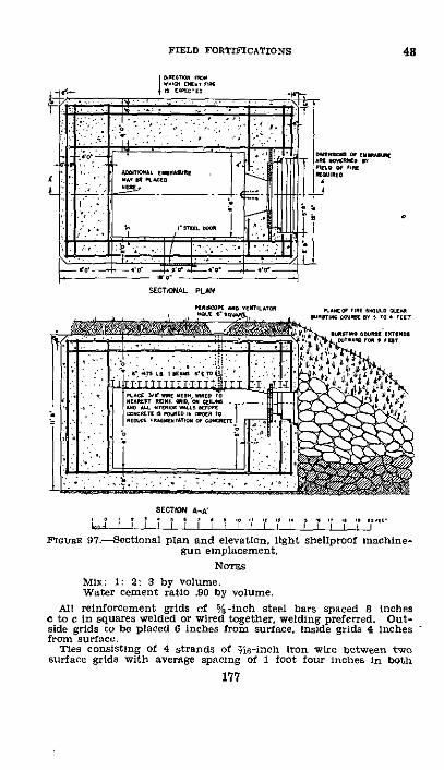
FIELD FORTIFICATIONS 48
4 ne r > ,. rar r·
r~~~~ou .1 tZ _lr40 -d~N -~
' tqL i : n32wuf
AO1CA .NNSN .. , .'-I' i EO
_ <o_
ksn
SCTEWAL PLN
:A N.OTN C, X TON D SC
: . '·. . ,'r EI. ' t 1
1X0 YT,..N , OI=N
SECTION A-A
FiGRmE 97.Sectional plan and elevation, light shellproof machine-gun emplacement.
NoDEs
MiX: 1: 2: 3 by volume.Water cement ratio .90 by volume.
All reinforcement grids of %-inch steel bars spaced 8 inchesC to c in squares welded or wired together, welding preferred. Out-side grids to be placed 6 inches from surface, inside grids 4 inchesfrom surface.
Ties consisting of 4 strands of $i6-inch iron wire between twosurface grids with average spacing of 1 foot four inches in both
177

ENGINEER FIELD MANUAL
directions: stirrups of %-inch metal between inner front andrear surface grids with average spacing 3 feet O inches horizontallyand 8 inches vertically.
Concrete faces not protected by earth or bursting courses maybe faced with '/,-inch to 1-inch steel plates if attack by infantryweapons at close range is anticipated.
The design should be regarded as typical and a guide for em-placements to meet tactical needs of a locality. Additional firingports may be provided and shape of the emplacement modified.Emplacements should be sited normally in groups for enfiladingfire and should be mutually supporting within groups.
The disadvantages of covered emplacements are that they re-quire considerable time for their construction, they seldomcan be constructed in near presence of the enemy, and it ispractically impossible to render them invisible in open terrainto hostile observation. The view and the field of fire are alsonecessarily greatly restricted. In order to reduce risk ofshell fragments or rifle bullets entering the embrasure thefield of fire is generally limited to about 60 °.
(b) Light shellproof reinforced concrete-Figures 97, 98,and 99 show an emplacement providing protection against155-mm shells. A shelter of the same dimensions but withoutloopholes may be used for sheltering two gun crews to operatemachine guns from nearby open emplacements. In this caseit should be lowered so as to be concealed more easily, andthe thickness of the floor may be reduced to 12 inches. Dueto the large amount of material and more or less elaborateconstruction plant required, use of concrete emplacements isrestricted to positions not under direct observation of theenemy and provided with good transportation facilities, pref-erably near a railway line.
A minimum period of 2 weeks must be allowed for harden-ing of portland cement so that the emplacement may beconsidered effective, and 1 month for it to attain practicallyfull strength. High early strength cement attains an effec-tive strength in 24 hours. In soft ground in order to pre-vent shells from penetrating and exploding under the floor,a course of broken rock as indicated in the figure, or con-crete bursters (see fig. 121) should be placed protecting theexposed sides. The embrasure is fitted with a pair of armorsteel doors set in the concrete. The steel doors are sufficientlythick to withstand armor-piercing caliber .50 machine-gunfire. Table XXIV gives material list and work data.
178
48

SECTIONAL PLAN OF EMBRASURE
orDill z dio.I*' di RiletsU. ma in
I I
I
Ietriing
5 67'- O"
STRUCTURAL STEEL EMBRASURE PLATEI o0 1 3 4 5 FEET
.L ,,Il 1 I P I-
PORT
Iu mr 3d 4 5 FEET-irj, , .... I I I I I
PLAN
NOTE- FIRING TESTS INDICATE THATDIAGONAL BRACES (S) ARE NOT RE-
QUIRED WHEN FIRING CAL. 30 AND CAL.
D50 M.G. DESIRABLE, BUT NOT ESSEN-
TIAL WHEN FIRING 37 MM. GUN.
aITRIPOD MOUNT
I 0 I 4 5 6 7 T a s 10 II 1 FEETl F I I I I I
I 0 1 2 3 4 5 FEET1,,1 ,1 1 1 I i I
' rF-- ..... = wr r.'. ',I
ARhOR-PLATE OOORS
sIgs: I 1 8 bnci. i tfo
I r * ILS l. S . NAE
t-.^l "'
PORT COVER ASSEMBLY
T,,,,,,,,p i.Er
10 ilLEFT CLAMP RIHT CLAMP
_ w I ird '
T WO D ..s .. ...BOLT FOR OOOR CLAMP
FIGN 9g.--Section and dietails of embrasure and tripod mount, light shellproof machine-gun emplacement.
26237540 (Face p. 179)
I
O d..M ml, 7 h.I
`3 -6d(mot
I

FIELD FORTIFICATIONS 48
40 0
22~r
CR 0
z~~~~
0 0 5~~~~~~~~~~~0
4 , 0~~~~~~~~~~~~ a ~ 0
,j~ .-
jo~
z'e
r " - ~ x~ f --
a, m
;I5-I
on['- .
0
;~~~:o T~~~~~~ 4: ~~~~~-:O E~~~~~~'r L___j~~~~~
179

48 ENGINEER FIELD MANUAL
TABLE XXIV.--Material list and work data for light shell-proof machine-gun and 37-mm gun emplacement (figs.
. 97, 98, 99)
Item
Cement ............-........
SandBroken stone or gravel (for cement)...Water.
I-beams, 6-inch .....--
Round iron bars for reinforcing grids3-inch.
Iron wire for stirrnps, 3 s-inch..Angles for embrasure corner armor....
3 each 4 by 4by 9y inch by 6 feet 4inches.
I each 4 by 4 by if6 inch by 5 feet8 inches.
2 each 4 by 4 by 94a inch by 2 feetI 1 inches.
2 each 4 by 4 by 9lo inch by 1 foot7 inches.
Wire mesh, 3t-inch for ceiling and walls.-Embrasuro panels complete, consisting
of-I armor steel plate 1 inch by 3 feet 6
inches by 5 feet 6 inches.1 armor steel plate 2 inches by 2 feet
10 inches by 7 feet.1 armor plate door 3 feet 2½ inches by
1 foot 2i inches by 4 inches thick,with hinges, door clamp assembly,and port cover assembly.
6 angles 2 by 2 by 3t inch by 9½jinches long.
Steel door for port complete, consistingof-
I steel plate 2 feet 6 inches by 6 fcetby 1 inch thick.
2 angles 2 by 2 by 3 inch by 5 feet6 inches.
Unit
Barrels (approxi-mately 4 cubicfeet per barrel).
Cubic yards.do ....
Gallons .
Pieces 9 feetinches long.
6
Linear feet .....
. do.....
Square feet ......
180
Quantity
143
4364. 5
3, 800(approxi-mately)
24
6, 900
1,60052
263
I
Weight(tons)
26. S
538816
1.7
3.6
.08.40
.201.6
.35
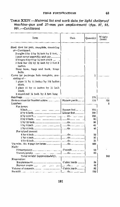
FIELD FORTIFICATIONS 48
TABLE XXV.--Material list and work data for light shellproofmachine-gun and 37-mm gun emplacement (figs. 97, 98,99) .- Continued
Item
Steel door for port, complete, consistingof-Continued.
2 angles 2 by 2 by 3t inch by 2 fect1 port cover assembly and cap...2 hinges 4 by 6 by i inch thick..I lock bar 1½ by M inch by I foot 3
inches.Door hook, hasp and book, hinge
bolts.Cover for pcriscole hole complete, con-
sisting of1 plate 11 by 11 inches by lt inches
thick.I plate 11 by 1I inches by 16 inch
thick.I round rod ti inch by 3 feet long
Sandbags -- - -.................Broken stone for burster course..Lumber:
For formn:2-inch - ------ ---------2 by 6 inch ........... --2by4inch2 byl inch ................1 by 12 inch.1 by 6 inch - ------1 by 4 inch .
For tripod mount:4 by 4inch.Ihby4inch2by 6inch
Tie w ire. No. 9 gage for forms - -.... --Nails:
Sixteenpcneny.Twoentype nny
Total weight (approximately) -.Excavation:
EmrplacementBurstercourse ...
Unit
Square yards. .-
Square feet.....Linear feet.
--. do,.. -- --..........
. do ...
do
.. do .....
_do.. do.....
Pounds ....o...._ do ..
Cubic yards ...do..
Volunle of concrete Cubic yards ...Backfill do...........
181
Weight(tons)
1655
363
Quantity
1
174110
07570033036604040
223731
800
6060
584982
120

ENGINEER FIELD MANUAL
TABLE XXIV.-Material list and work data for light shellproofmachine-gun and 37-mm gun emplacement (figs. 97, 98,99) .- Continued
Item Unit
_
Work:Excavation and fill Man-hours 320Erecting forms, placing burstcr .....do........ 350
course, etc.Concrete, placing reinforcing, mixing, - do ..--..... 450
placing, and stripping forms.
Total .....................-... do....... 1, 120Total, 8-hour shifts, 20 men - - 7
Period for hardening (minimum):Portland cement .............. Days........- - 14High early strength cement -..... l..ours ........ 2
(5) Additional types.-(a) Figure 100 shows a light shell-proof emplacement connected with an underground shelter.
(b) Figure 101 shows a machine-gun emplacement insidea ruined house.
(c) Protection and concealment for covered emplacementsmay be obtained in a variety of ways, depending on proximityof the enemy, local resources in material, and amount oflabor available.
f. Ventilation of covered emplacementsVentilation ofcovered emplacements is most important due to the quanti-ties of carbon monoxide liberated during firing of machineguns. The gas is highly toxic, odorless, and colorless. Venti-lation of covered machine-gun emplacements in order to freethem of this gas takes precedence over protection againstenemy gas. It is desirable to have on hand in emplacementsdifficult to ventilate by ordinary means a hand-operated port-able blower similar to that on a blacksmith's forge. In addi-tion a gas curtain placed between the muzzle of the gun andthe firer will exclude a large proportion of the gas.
A removable metal sleeve slightly larger than the jacketof the gun may be made to fit over the outside of the barreland jacket and to project a few inches beyond the muzzle.
182
48
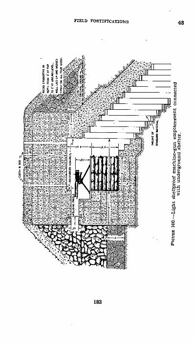
FIELD FORTIFICATIONS
t
0
C
aC)
183
48

ENGINEER FIELD MANUAL
1 M
184

FIELD FORTIFICATIONS 48
It is not necessary that this sleeve project outside the loop-hole. Action is that firing of the gun causes a vacuum insidethe sleeve which draws in air from the rear. The powerfulforward blast of air so caused blows all gases out of theloophole. Use of this device has been found highly satisfac-tory in exclusion of gases. It should always be providedwhen thickness of walls of the emplacement is such as tomake it difficult or even impossible to project the muzzle ofthe gun outside the edge of the loophole.
g. Time and labor estimates for emplacements.-See tableXXV below.
TABLE XXV.-Time and labor estimates for emplacements,using pioneer tools
Emplacementdescription
Automatic rifle ..Machine gun:
Light:Shallow...Standing.....
Heavy:Shallow .Standing
Caliber .50:Shallow-.......Standing.. -
Splinterplroof,double.
Reinforced con-crete.
37-umm gun.M 1916:
Shallow .-- -
Standing....-..AntitankMortar:
81-mm ...--am .....
Cubic feetexcavationrequired
37 -..
15 ....5 .
60 -120.
75 ....150 -......
Man-hours .
(approxi-n; e,
Reference itthis manual
1½f to 4.. I Fig. 87._
tol _ I Fig. 916 to 10. -- Fig. 91 -.
3to7 _.7 to 132.
3, to 9 t
1,1208 _
1,120 -
Fig. 89Fig. 90
Par. 4d (
Fig. 96..
Figs. 97,. i
(6)
Remarks
- - Materialatsite.
)8, 99 Do.
--. --. 5 . 21 ito 6 Fig. 02.118 7 to 13 Fig. 9 2175to
2 0.. 10to24. Fig 93
.------60 - .-- -
9 to 18- F;..;3 to .... I Fig. 943P-ig, 95
First figur is for soft earth, the second for hard earth.Do-s not ineludo revetments.
185
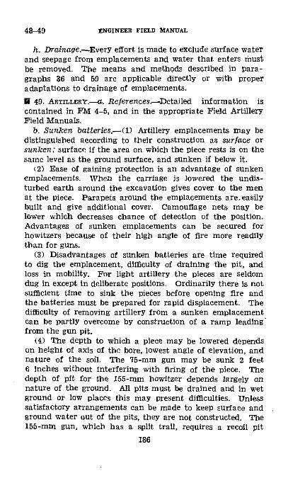
48-49 ENGINEER FIELD MIANUAL
h. Drainage.-Every effort is made to exclude surface waterand seepage from emplacements and water that enters mustbe removed. The means and methods described in para-graphs 36 and 59 are applicable directly or with properadaptations to drainage of emplacements.
E 49. ARTLLERY.-a. References.-Detailed information iscontained in FM 4-5, and in the appropriate Field ArtilleryField Manuals.
b. Sunken batteries.-(1) Artillery emplacements may bedistinguished according to their construction as surface orsunken; surface if the area on which the piece rests is on thesame level as the ground surface, and sunken if below it.
(2) Ease of gaining protection is an advantage of sunkenemplacements. When the carriage is lowered the undis-turbed earth around the excavation gives cover to the menat the piece. Parapets around the emplacements are.easilybuilt and give additional cover. Camouflage nets may belower which decreases chance of detection of the position.Advantages of sunken emplacements can be secured forhowitzers because of their high angle of fire more readilythan for guns.
(3) Disadvantages of sunken batteries are time requiredto dig the emplacement, difficulty of draining the pit, andloss in mobility. For light artillery the pieces are seldomdug in except in deliberate positions. Ordinarily there is notsufficient time to sink the pieces before opening fire andthe batteries must be prepared for rapid displacement. Thedifficulty of removing artillery from a sunken emplacementcan be partly overcome by construction of a ramp leadingfrom the gun pit.
(4) The depth to which a piece may be lowered dependson height of axis of the bore, lowest angle of elevation, andnature of the soil. The 75-mm gun may be sunk 2 feet6 inches without interfering with firing of the piece. Thedepth of pit for the 155-mm howitzer depends largely onnature of the ground. All pits must be drained and in wetground or low places this may present difficulties. Unlesssatisfactory arrangements can be made to keep surface andground water out of the pits, they are not constructed. The155-mm gun, which has a split trail, requires a recoil pit
186

FIELD FORTIFICATIONS
approximately 2 feet 6 inches deep for high angle fire. Thesecharacteristics in addition to the great weight and difficultyof maneuver preclude lowering this gun below the ground sur-face. Emplacement of the 240-mm howitzer requires excava-tion of a large pit for its platform which is located at thecenter of a cleared level space. It is therefore impracticableto sink the upper level of the platform below the groundsurface.
(5) The 75-mm gun in a sunken position and with para-pets is shown in figure 102 (D and ®. As shown in O anembrasure is cut in the ground surface to permit furtherlowering the piece. This embrasure and all excavated ma-
/4 i'•KI' 7:'111l 7^'1K ' I ' I64 ?' i*GROUMN LEEVEL' :/11 //r
(D Without embrasure.4 ,.,. ~ .. ." .- .- O-as ;o'
Cfha
cGwrE 102-75-mm gun in sunken position.
terial must be included under the camouflage net or other-wise concealed. Before deciding upon the depth of the pit,it must be ascertained whether the embrasure will requirean excessive amount of work or extend too great a distancein front of the gun. The platform for the piece should notbe given its final depth until the embrasure is completed.Where no embrasure is to be cut, depth of the pit is readilyobtained from height of the bore and elevation of thepiece. In all sunken batteries a suitable ramp leads to theplatform for the piece. Slope of this ramp is approximately1 vertical to 5 horizontal.
187
49

49 ENGINEER FIELD MANUAL
PlGroat 103.-75-mm gun in bank along edge of road.
IoGrEa 104,-155-mm howitzer in bank along edge of road.
FIGuRE 105-155-mm howitzer in bank in edge of woods along road.
188
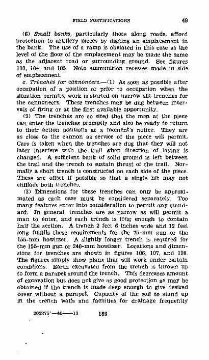
FIELD FORTIFICATIONS 49
(6) Small bancs, particularly those along roads, affordprotection to artillery pieces by digging an emplacement inthe bank. The use of a ramp is obviated in this case as thelevel of the floor of the emplacement may be made the sameas the adjacent road or surrounding ground. See figures103, 104, and 105. Note ammunition recesses made in sideof emplacement.
c. Trenches for cannoneers.--() As soon as possible afteroccupation of a position or prior to occupation when thesituation permits, work is started on narrow slit trenches forthe cannoneers. These trenches may be dug between inter-vals of firing or at the first available opportunity.
(2) The trenches are so sited that the men at the piececan enter the trenches promptly and also be ready to returnto their action positions at a moment's notice. They areas close to the cannon as service of the piece will permit.Care is taken when the trenches are dug that they will notlater interfere with the trail when direction of laying ischanged. A sufficient bank of solid ground is left betweenthe trail and the trench to sustain thrust of the trail. Nor-mally a short trench is constructed on each side of the piece.These are offset if possible so that a single hit may notenfilade both trenches.
(3) Dimensions for these trenches can only be approxi-mated as each case must be considered separately. Toomany features enter into consideration to permit any stand-ard. In general, trenches are as narrow as will permit aman to enter, and each trench is long enough to containhalf the section. A trench 2 feet 6 inches wide and 12 feetlong fulfills these requirements for the 75-mm gun or the155-mm howitzer. A slightly longer trench is required forthe 155-mm gun or 240-mm howitzer. Locations and dimen-sions for trenches are shown in figures 106, 107, and 108.The figures simply show plans that will work under certainconditions. Earth excavated from the trench is thrown upto form a parapet around the trench. This decreases amountof excavation but does not give as good protection as may beobtained if the trench is made deep enough to give desiredcover without a parapet. Capacity of the soil to stand upin the trench walls and facilities for drainage frequently
26235'---40 13 189

ENGINEER FIELD MANUAL
determine which method may be adopted. Should it befound necessary, the trench may be braced as shown infigure 26.
d. Parapets.-(1) After the piece is in firing position andthe narrow trenches have been dug for the cannoneers, para-
FGcuRE 106.-Emplacement for 75-mm gun (French 75-mm, highspeed rubber-tired wheels).
pets are thrown up around the piece or piece and caisson toprotect matdriel and personnel. In addition to giving actualcover the parapet gives the men a greater sense of securityand has a certain moral effect that increases efficiency ofthe cannoneers under fire.
190
49

FIELD FORTIFICATIONS
(2) Location and size of the parapet depend largely onground, tactical situation, and type of piece. The parapetis as close to the piece as will permit necessary movement atthe emplacement. The inner slope is close to the piece
'v 'Tl'" ~*'~- " "~' ~ P~ *'*"uzt-?-.7.-- ,- r :6s
e.2 ection A-.C-P
Founs 107.-Emplacement for 155-mm howitzer, M1918 (highspeed).
wheels. Height of the parapet is such as to give maximumcover to the cannoneers, not less than 4 feet, approximatelyheight of the wheels. For complete cover the height is 6 feet6 inches above the platform or surface on which the carriagerests.
191
49

49 ENGINEER FIELD MANUAL
(3) When lower angles of fire are used for a gun an open-ing may be left in the parapet, the width of which is depend-ent on traverse necessary. The parapet is made splinter-proof, requiring thickness at the top of at least 2 feet 6 inches.A greater thickness is obtained whenever possible.
4 ~ ~ ~ ~ ~ 4Ua,~~~el \SSI ,IC \
Ii\
I I
/
Secion. A-DiFGUcRE 108.-Emplacement for 155-mm gun.
(4) Earth is not borrowed close to the foot of the exteriorslope since future enlargement of the parapet may be de-sirable. Unless revetted, the exterior slope should not besteeper than 1 on 1.
(5) Parapets erected around surface batteries are shownin Figures 106, 107, and 108. Location and dimensions of theelements shown in these figures are given as a guide and not
192
\

FIELD FORTIFICATIONS
as a standard. With necessary modifications in shape anddimensions similar emplacements can be constructed for alltypes and models of weapons. In a deliberate type of defensethe caisson is not included within the parapet. Also in thiscase, when the nature of the ground permits, the piece maybe sunken to give cover without building up the parapet. Inall cases precautions are taken to conceal the position beforeany work is done. It is useless to conceal a position whichhas been built within view of the enemy.
(6) If the space occupied by the piece and caisson is exca-vated to a depth of approximately 1V/2 feet, sufficient earthis obtained to construct the parapet to give 4 feet of cover.This method usually reduces difficulties of concealment.
e. Concrete emplacement for 155-mm guns.-(1) A specialcase arises in Permanent emplacement of tractor-drawn ar-tillery for fire at naval targets. The principal considerationin such cases is to get a wider traverse than 600. The gunsare placed on concrete foundations on which there is a cen-tral platform, an annular recoil pit, and a 180 ° traversingcircle for the trails as shown in figure 109. Wheel shoes andspades are removed and spades replaced by steel guide platesbolted to the trails. These plates fit over the curved railroadiron which is imbedded in the semicircle of reinforced con-crete and which is anchored by steel hooks. A steel curb bandsurrounds the raised concrete inner circle and serves as aguide for the wheels of the carriage, thus preventing the trailplates from binding on the guide rail in traversing. Theguide rail and curb band are kept lubricated and the trailsmoved by hand as necessary. The gun is traversed in thenormal manner, the trails being moved only when necessaryto keep the target within the 60 ° traverse limit of the gun.Mobility of the gun remains the same.
(2) Slit trenches for the protection of personnel manninga gun on this type of emplacement must of course be placedoutside the concrete semicircle. A parapet having its insidewall along the diameter of the semicircle may be erectedand continued around the sides and rear of the emplacementso as to include the slit trenches. An embrasure must beleft in the front large enough to permit the piece to be firedfrom all positions throughout its 180 ° of traverse.
193
49
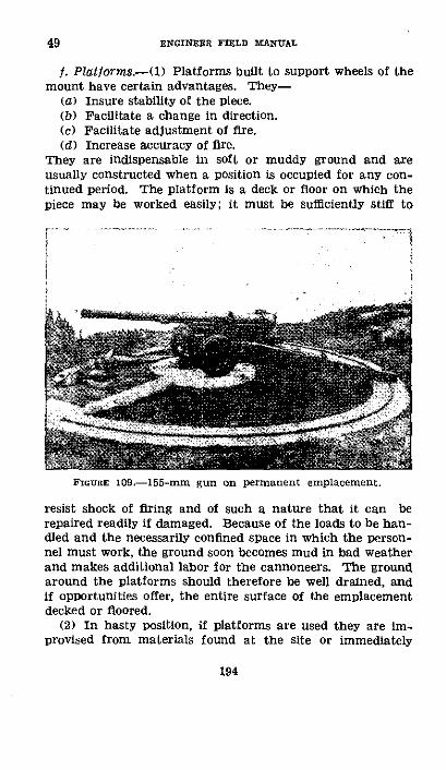
ENGINEER FIELD MANUAL
f. Platforms.-(1) Platforms built to support wheels of themount have certain advantages. They-
(a) Insure stability of the piece.(b) Facilitate a change in direction.(c) Facilitate adjustment of fire.(d) Increase accuracy of fire.
They are indispensable in soft or muddy ground and areusually constructed when a position is occupied for any con-tinued period. The platform is a deck or floor on which thepiece may be worked easily; it must be sufficiently stiff to
FIGURE 1-1- g oprn elmn
FIGURE 109.-155-mm gun on permanent emplacement.
resist shock of firing and of such a nature that it can berepaired readily if damaged. Because of the loads to be han-dled and the necessarily confined space in which the person-nel must work, the ground soon becomes mud in bad weatherand makes additional labor for the cannoneers. The groundaround the platforms should therefore be well drained, andif opportunities offer, the entire surface of the emplacementdecked or floored.
(2) In hasty position, if platforms are used they are im-provised from materials found at the site or immediately
194
49

FIELD FORTIFICATIONS
available. Brush, logs, planks, or broken stone can be usedfor this purpose. An improvised log platform may be con-structed quickly by burying three or four sills in the groundparallel to direction of fire and laying a row of logs uponthem at right angles. They can be held in place by wiringor spiking the top layer to the sills or by covering the entireplatform with about 6 inches of earth (fig. 110). In anycase, the completed platform should not be higher than theground on either side of it. If broken stone is available, abetter bearing surface for the gun may be made by excavat-ing and filling with stone.
(3) In deliberate positions wooden platforms are constructedand may be made of standard dimensioned timber obtainedfrom the supply service. Due to their weight it is not feasible
LARGC L$GSLAI PARALLEL 1O LIE: OF RS
FGiaR 110.-Improvised log platform.
to have the platforms made up in the rear and brought forwardassembled. Concrete platforms are not recommended forpieces not specially designed to be fired from concrete basesas they are not sufficiently resilient to take up the shock of therecoil without injury to the piece. Wooden platforms aresimple in design, made of standard size lumber, and sufficientlystrong to support the weight. It is desirable to make themlarge enough to provide space for the men loading the piece.
(4) The 75-mm guln platform shown in figure 111 consistsof sills, posts, and deck. It is given as a guide for constructionof similar platforms to accommodate the various types andmodels of field artillery, it being necessary only to vary the sizeof the platform for the particular weapon.
195
49
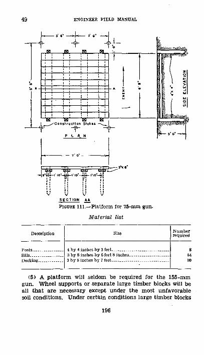
49 ENGINEER FIELD MANUAL
,*' " .-
*"4 -, - : I I-I- 3'044,
I , 4IV 'V % V
SECTION AA
ioGURE 111.-Platform for 75-rm gun.
Material list
Size
4 by 4 inches by 3 feet......3 by inchebs by 6 feet 8 iaches3 by 8 inches by 7 feet .........
196
Description
Posts....Sills ........Decking...........
Numberrequired
(5) A platform will seldom be required for the 155-mmgun. Wheel supports or separate large timber blocks will beall that are necessary except under the most unfavorablesoil conditions. Under certain conditions large timber blocks

FIELD FORTIFICATIONS
placed under the wheels suffice. By use of these less diggingis involved both for the recoil pit and in the use of jacksthan when the piece rests on the wheels or track shoesalone. Moreover, the gun can be placed in position in slightlyless time. The specially prepared wheel support is madeof two runners wide enough to give full bearing to the wheels,strong enough to support the load, and braced to preventtwisting or movement out of line (see fig. 112).
Material list
Description Size Numberrequired
Crosspieces ....... 3 by 8 inches by 8 feet 7 inmbes ........-..Runners .....-.. 14 by 14 inches by 14 feet -2Bolts ............- by 15 inches ...-............... 12
g. Trail supports.-(1) A trench for the trail spade of the75-mm gun or the 155-mm howitzer is dug immediately uponoccupation of the position. For continuous firing additionalsupport must be given spades. The trail supports preventdisplacement in traversing, assist in shifting the trail, andfacilitate rapid change of target.
(2) In a hasty position, the support consists of a log ortimber set in the earth behind the spade to distribute theforce of the recoil transmitted through the trail. A logat least 6 inches in diameter and 4 feet long should be usedfor the 75-mm gun; it is held in place by a strong picketnear each end. The bottom of the log is at least 1 foot belowthe ground surface. Broken stone or similar material placedin rear of the log will assist in holding it in position. Asupport built of sandbags will hold for a limited time pro-vided the spade does not rest directly against the bags. Afascine used in place of the log will adjust itself to the spadeand give a better cushion. For the 155-mm howitzer a log atleast 8 inches in diameter and 6 feet long is used. Due tothe heavy blow delivered by the spade the log must beheld firmly in place by strong pickets and a cushion of
197
49

ENGINEER FIELD MANUAL
Pl anFIOtGE 112.-Wheel
Sectiorsupport for 155-mm gun.
198
49

FIELD FORTIFICATIONS 49
broken stone or similar material placed in rear of the log.Sandbags are of little use for the trail of this howitzer.
(3) In a deliberate position, particularly where platformsare used, a more permanent support is built. Such a trailsupport for the 75-mm gun made of 8- by 10-inch timbersand 4 by 4 posts is shown in figure 113. The timbers are cutto shape in rear areas and furnished as shown in the figure.
spade
Secthon A-AFiGmuR 113.-Trail support for 75-mm gun.
A wooden block shaped to the arc of travel is fastened tothe spade. The timber supports are held in place by stakesand by a backing of broken stone in a trench. When in-creased ranges and high angle fire are required, an additionaltrail support is constructed in a similar manner inside ofand lower than that shown in figure 113. The depth belowthe surface depends on elevation to which the gun is to beraised. If no dimension timber is available, a support of thistype may be built of fascines and 3- or 4-inch round pickets.The fascines are cut to 4-foot lengths. No wooden block
199
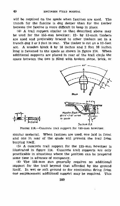
ENGINEER FIELD MANUAL
will be required on the spade when fascines are used. Thetrench for the fascine is dug deeper than for the timberbecause the fascine is more difficult to keep in place.
(4) A trail support similar to that described above maybe used for the 155-mm howitzer; 12- by 12-inch timbersare used and preferably braced to other timbers set in atrench dug 2 or 3 feet in rear. The timber is cut on a 12-footarc. A wooden block 8 by 16 inches and 2 feet 10 incheslong is fastened to the spade as shown in figure 114. Whenadditional supports are placed in rear of the trail circle thespace between the two is filled with broken stone, brick, or
Wooden §lockrx8I,:g.?:ow7r ed 'l ,
5eclioO AAFIGURE 114.-oncrete trail support for 155-mm howitzer.
similar material. When fascines are used, one laid in frontand one in rear of the spade will prevent the trail fromburying itself.
(5) A concrete trail support for the 155-mm howitzer isillustrated in figure 114. Concrete trail supports are onlypracticable in situations where the position can be preparedsome time in advance of occupancy.
(6) The 155-mm gun generally requires no additionalsupport for the trail beyond that afforded by the grounditself. In wet or soft ground or for continuous firing fromone emplacement additional support may be required. This
200
49

FIELD FORTIFICATIONS 49-50
can be provided easily by placing a large log or timber underthe shoe normal to the trail. The timber preferably shouldbe about 12 inches square in section and 12 feet long, extend-ing 6 feet on each side of the center of the trail, and placedflush with the ground surface. If smaller timbers or logs areto be used, they are placed one on top of the other in a trenchof the proper depth.
hI. Drainage.-See paragraphs 36, 48h, and 59.
* 50. ANTIAIRCRAFT MATfRIEL.-a. Concealment and camou-flage will provide the most effective protection for antiaircraftguns, searchlights, power plants, and accessories. When infiring and operating positions, antiaircraft materiel is some-times difficult to conceal and, whenever the situation permits,protection for mat6riel and personnel will be provided. Thiswill normally consist of sunken emplacements or parapetsbuilt up around the unit of materiel or perhaps a combinationof the two. In the case of parapets splinterproof protectionshould be provided as a minimum. Suggestions for suchprotection are given below, These suggestions should notbe considered as definite methods for the various units ofmateriel shown since field conditions will require modi-fications or changes for each case. Dimensions shown willnot necessarily be correct for all equipment but are givenwith the idea of providing minimum protection without limit-ing capabilities of the materiel.
i. The most effective protection for searchlights againstenemy gunfire or air attack is afforded by concealment ofthe lights when not in action, and by concealment of thepower plants. Mobile lights should be kept in concealedpositions during daylight hours, and their operating positionsshould be changed frequently. When the time is availablea limited amount of protection should be provided for materieland personnel by digging circular pits or erecting parapetsof such depth or height, respectively, as will not interferewith the beam or obstruct the field of view in any direction.Mobile power plants for searchlights should be located in awood, ravine, or other depression, and defiladed from enemyfire, The distance between the light and the power plantshould be the maximum consistent with length of the cable.
201
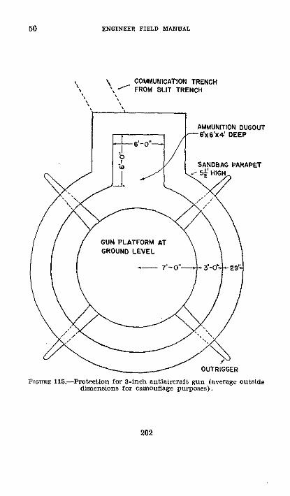
ENGINEER FIELD MANUAL
COMMUNICATION TRENCH
FrormE 115.-Protection for 3-inch antiaircraft gun (average outsidedimensions for camouflage purposes).
202
50
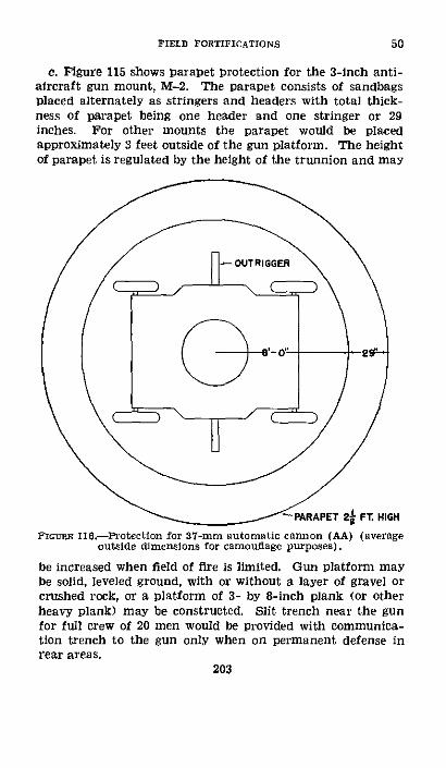
FIELD FORTIFICATIONS
c. Figure 115 shows parapet protection for the 3-inch anti-aircraft gun mount, M-2. The parapet consists of sandbagsplaced alternately as stringers and headers with total thick-ness of parapet being one header and one stringer or 29inches. For other mounts the parapet would be placedapproximately 3 feet outside of the gun platform. The heightof parapet is regulated by the height of the trunnion and may
PARAPET 2 FT. HIGH
FIGnrE 116.-Protection for 37-mm automatic cannon (AA) (averageoutside dimensions for camouflage purposes).
be increased when field of fire is limited. Gun platform maybe solid, leveled ground, with or without a layer of gravel orcrushed rock, or a platform of 3- by 8-inch plank (or otherheavy plank) may be constructed. Slit trench near the gunfor full crew of 20 men would be provided with communica-tion trench to the gun only when on permanent defense inrear areas.
203
50

ENGINEER FIELD MANUAL
d. For complete details see FM 4-105.e. Figure 116 shows similar parapet protection for 37-mm
automatic cannon (AA). The height of the parapet is basedon trunnion height of 33 inches. The height of the parapetmay be increased when field of fire is limited but must alwayspermit maximum possible field of fire. No slit trenches or
'"PARAPET 3FT. HIGHFrounE 117.-Protection for antiaircraft searchlight (average outside
dimensions for camouflage purposes).
communication trenches are provided as camouflage must bechief protection. Wheel supports may be provided in wetor soft soil.
f. Figure 117 shows similar parapet protection for anti-aircraft searchlights. The parapet height of 3 feet permits
204
50

FIELD FORTIFICATIONS 50
100 elevation and this height of parapet may be increasedwhen field of fire is limited. Wheel supports may be providedin wet or soft soil. One-man slit trench alongside light foroperator is shown.
FIGURE 118.-Protectlon for director, gun battery (ramp or othermeans of emplacing instruments are not shown).
g. Suggestions for protection of other matdriel are asfollows:
(1) Searchlight unit.-(a) Control station.-Dig circularpit about 21 feet in diameter and 4 feet deep,
262375 ' 0-- 14 205
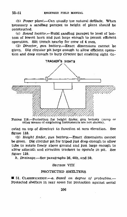
50-51 ENGINEER FIELD MANUAL
(b) Power plant.--Can usually use natural defilade. Whennecessary a sandbag parapet to height of plant should beconstructed.
(c) Sound locator.-Build sandbag parapet to level of bot-tom of lowest horn and just large enough to permit efficientoperation. Slit trench nearby for crew of 4 men.
(2) Director, gun battery.-Exact dimensions cannot begiven. Dig circular pit large enough to allow efficient opera-tion and deep enough to bury director but enabling sight (lo-
TRACKER'S SIGHTS
FiGURE 119.-Protection for height finder, gun battery (ramp orother means of emplacing instruments are not shown).
cated on top of director) to function at zero elevation. Seefigure 118.
(3) Height finder, gun battery-Exact dimensions cannotbe given. Dig circular pit for tripod just deep enough to allowtube to rotate freely above ground and just large enough toallow azimuth and elevation trackers to operate in pit. Seefigure 119.
h. Drainage.-See paragraphs 36, 48h, and 59.
SECTION VIII
PROTECTED SHELTERS
* 51. CLAssrICATIoN.-a. Based on. degree of protection.-Protected shelters in rear areas for protection against aerial
206
FIELD FORTIFICATIONS
bombardment are necessary. An indication of degree of pro-tection necessary against airplane bombs is given in paragraph29. However, sufficient experimental data and experience arenot available on this subject to state that a particular airplanebomb requires the same degree of protection as a certain artil-lery projectile. Therefore protected shelters are classifiedaccording to degree of protection they afford against artilleryprojectiles, as-
(1) Splinterproof shelters protect against rifle and ma-chine-gun fire, splinters of high-explosive shell, and grenades,but not against direct hits by 3-inch shells. They require onlythat an overhead cover of compact earth of about 1 foot inthickness (or its equivalent in other material) be securelysupported. When these shelters are numerous and are care-fully located, casualties may be greatly reduced.
(2) Light shelters protect against direct hits and in somecases against a continued bombardment by 3-inch shells.
(3) Light shellproof shelters protect against continuousbombardment by all shells up to and including 6-inch.
(4) Heavy shellproof shelters protect against continuousbombardment by at least 8-inch shells. Some types may beproof against larger shells or against all types of artillery fire.
b. Based on method of construction.-Shelters may fur-ther be classified according to method of construction whichdepends on character of the ground, materials available, andprotection required as-
(1) Surface.-These structures or at least the greater por-tion of them are built at or above the surface of the ground.This type has maximum observation and exit facility andrequires a minimum of labor: on the other hand, it is rela-tively conspicuous, requires considerable cover material, andprovides the least protection. Shelter of this type is seldomused for protection of personnel in advanced lines unless itcan be concealed in woods, on a steep reverse slope, or amongthe buildings of a village, or unless the underground waterlevel is so close to the surface that the cut-and-cover typecannot be used. However, one exception to this rule may bethe reinforced concrete shelter though this type often ap-proaches cut-and-cover construction. Light shelters con-sisting of almost any type of small improvised shed covered
207
51

51 ENGINEER FIELD MANUAL
with a layer of earth may be used for protection of ammu-nition and stores. These shelters should be of small capacity,well dispersed, and carefully concealed.
(2) Cut-and-cover.-(a) This type consists of an openexcavation in which framework for the shelter is placed, afterwhich the excavation is backfilled around and over theframework to the level of the original surface, or somewhatabove. To increase resisting power of overhead cover con-crete, steel beams, broken stone, and other materials of highresistance to penetration are used in roof construction. It isa type intermediate between the surface and the cave shelter.* (b) Comparing it with the cave, the cut-and-cover shelteris adapted for use as dressing stations because it is easilycleaned, is well ventilated and lighted, and facilitates readyadmission and evacuation of casualties. Cut-and-covershelters are generally more quickly constructed but requiremuch larger quantities of material than cave shelters. Theydo not resist intensive shelling as well and are more difficultto conceal than cave.
(c) When surface and underground water or hardness ofunderlying rock makes construction of cave shelters imprac-ticable, cut-and-cover shelters may be used. They are alsoused where need for rapidity of exit prohibits use of caveshelters (as in important machine-gun shelters in or nearthe front line), in wooded areas or in buildings where con-cealment is easy and where ample material is available, andin situations requiring immediate shelter which can be mostquickly obtained by this type.
(d) A cut-and-cover shelter providing protection against6-inch shell does not usually present great difficulties, butit is generally impracticable to attempt to gain protectionby cut-and-cover methods against- heavier shell withoutconstructing the shelters partially or entirely of concrete.
(3) Concrete shelters.-With adequate plant and materialsfor aggregate and for forms, protection may be obtainedby either surface or cut-and-cover methods by constructionof concrete shelters.
(4) Cave shelters.-(a) Cave shelters are constructed en-tirely below the surface of the ground by mining methodsand have a cover of undisturbed or virgin earth. They are
208
FIELD FORTIFICATIONS 51-52
the least conspicuous of all types, afford maximum protec-tion before the shelter can be completed, and require aminimum of material. They have the disadvantages oflimiting observation, unsatisfactory living conditions, diffi-cult exit, and difficult drainage and ventilation.
(b) It is difficult if not impossible to increase overheadprotection of these shelters after completion since protectiondepends upon depth at which the chamber is built. Forthis reason it is important not to underestimate amount ofprotection needed when the depth is determined. On theother hand, it is equally important not to overestimateamount of protection needed because of time, labor, andmaterial involved in going to unnecessary depths.
* 52. CHOICE OF TYPE.-The type adopted should be suitableto the situation; each selection is a separate and distinctproblem. The more important considerations are-
a. Tactical considerations and requirements.-(1) Theprimary purpose of a protected shelter is to permit troopsto remain at or very near their combat positions in com-parative safety during hostile bombardment. Therefore useand degree of protection necessary are usually the mostimportant tactical considerations.
(2) The terrain should be considered with especial refer-ence to slope and its effect on type of entrances and rapiditywith which overhead cover can be gained and the disposalof spoil. The existence of wooded areas and buildings whichprovide materials and facilitate concealment should also in-fluence the decision. Reverse slope positions are difficultfor artillery to hit and are usually drained easily.
(3) Location.-(a) Shelters should be near the combator assembly positions of troops occupying them. This ruleof the utmost importance near the front is of relatively lessimportance toward the rear.
(b) Facilities for cover and concealment afforded by ter-rain influence the location of shelters. Steep reverse slopes,quarries, etc., can be prepared to afford excellent shelterwith comparatively little labor. Every advantage should betaken of any natural shelter in the locality, tactical con-siderations permitting,
209

52 ENGINEER FIELD MANUAL
(4) Concealment.-(a) It is important that location andnumber of shelters be concealed from hostile air and groundobservation.
(b) Surface shelters to be inconspicuous must be hiddenby existing features of terrain as in a wood or amongbuildings in a village.
(c) For concealment cut-and-cover shelters must be keptlow. The surface of the ground where disturbed must berestored to its previous appearance. Necessary measuresmust be taken to conceal the work while in progress.
(d) Cave shelters are the easiest to conceal, as they donot disturb the natural surface of the ground. However,it is difficult to dispose of the spoil without attractingattention of the enemy.
(e) It is very important during construction to concealall signs of activity. Construction materials and excavatedearth must be carefully camouflaged and strict camouflagediscipline demanded of the men carrying on the work.
(f) Concealment is facilitated by placing the entrance toa shelter in a trench, thereby providing a protected outletand inlet and avoiding overground trails or footpaths.
(5) Observation.-Shelters should if practicable be lo-cated to afford necessary observation and be provided withmeans of observation such as loopholes in a surface shelteror a periscope in the roof of a cave shelter. The upper endof the periscope should be camouflaged.
(6) Priority order of construction.-In the ideal case thereshould be a sufficient number of shelters in a position to pro-vide cover for the normal defensive garrison, but due to thetime and labor involved as well as other considerations, thisis generally impossible. Hence the question arises as topriority for shelter construction. Order of priority dependsupon local conditions and cannot be stated definitely. Ingeneral, machine guns, observation posts, and command per-sonnel should receive first consideration.
(7) Application of types.-(a) Due to time element andconstruction difficulties, the light or splinterproof shelter isthe type usually employed during early stages of organiza-tion of the ground in mobile warfare. Necessity for shelter
210
FIELD FORTIFICATIONS 52
becomes greater as a condition of stabilization develops anddetails of the position become known to the enemy.
(b) Splinterproof shelters are desirable along importantcommunication trenches for protection of carrying parties,reliefs, litter bearers, and others who may be caught in abombardment.
(c) Light shelters are of value in consolidating positions.(d) In rear parts of the defended area, larger and deeper
shelters are both permissible and economical. These usuallyaccommodate one or two squads or a platoon, but companyand even battalion shelters may be used in certain cases.They may be developed from the light or splinterproofshelters constructed in emergency. Heavy shellproof andcave shelters are used only in stabilized situations.
(8) Requirements for shelter in advanced positions-(a)Shelters in advanced lines should be-
1. Well distributed, placing the troops close to theircombat positions.
2. Constructed without going to great depths in orderto provide for ease of exit.
3. Provided with a direct and easy exit (even at somesacrifice of cover).
4. Of small capacity (from 2 to 12 men).5. Of a type that can be constructed rapidly.6. Concealed as thoroughly as possible.
These requirements limit the type to the splinterproof orthe light shelter.
(b) Construction of light shelters is usually started byInfantry holding the front lines. They are located in indi-vidual rifle pits or in trenches resulting from organizing theposition. To prevent caving they are lined with logs ortimber, depending upon material available. They shouldhave at least 4 feet of cover.
(9) Requirements for shelters in rear positions.-Sheltersin rear positions may be larger and deeper than those atthe front. The occupants have more time to emerge afterwarning of attack has been received, and can occupy theirpositions more deliberately. They can be given maximumoverhead cover in order to withstand bombardment of heavyshells, giving troops occupying them necessary rest and feel-
211

ENGINEER FIELD MANUAL
ing of security. These shelters are built entirely belowground if underground water conditions permit. They arecarefully hidden from enemy aerial observation. Dependingon the situation, construction of these shelters may be byengineers, other troops, civilians under military control,civilian contractors, or any combination of these.
b. Technical considerations and requirements.-(l) Thesubsurface conditions, such as extent and character of under-lying rock, position and thickness of impervious and water-bearing strata, and amount of water to be controlled.
(2) Facilities available, including time, personnel, tools, ma-terial, and transportation.
(3) Facility of exit.-In order that a shelter may performits proper function, it must provide means for rapid egressof its occupants. This is particularly important in the caseof shelters located near the front where troops must be ableto make their exit and occupy their fighting positions afterenemy bombardment has ceased and before assault troopsenter defensive works.
(a) Facility of exit is secured by designing shelters ofsmall capacity, a minimum depth below ground, and havingunrestricted entrances.
(b) Large shelters are provided with at least two entrancesand preferably with a third for emergency use. This sup-plementary exit should emerge in a different trench fromthe other two, or at least at some point well concealed orcamouflaged, permitting the garrison to escape and launch acounterattack on an enemy attacking the main entrance.Entrances should be spaced to avoid the danger of one shellburst blocking two of them (a minimum of 40 feet apart andseparated by an angle in the trench). Large systems of caveshelters should be constructed to provide one entrance forevery 25 men.
(4) Drainage, ventilation, and gasproolng.--(a) Drain-age.-In the case of surface shelters drainage presents fewdifficulties. In the case of deep shelters it sometimes becomesa complex problem which includes-
1. Exclusion of surface water from the entrance.2. Exclusion of seepage from the interior.3. Removal of water that has collected in the interior.
212
52

FIELD FORTIFICATIONS
For further details, see paragraph 59.(b) Ventilation.-In surface or cut-and-cover shelters
ventilation presents no great problem, but in the cave shelterwith its underground chambers it becomes of vital impor-tance. Ventilation is provided by entrances and by open-ings through the roof, all so equipped that they can beclosed to exclude gas. For further details see paragraphs60, 61 and 62,
(c) Gaproofing.-It should be possible to make all sheltersand particularly those below ground gastight. A shelter notin use should be sealed to exclude gas, otherwise casualtiesmay occur when it is again used. For details of gasproofing,see paragraph 62.
· 53. OvERHEAD COVER,--a. Thickness.-Thickness of over-head cover is governed by the-
(1) Character of covering material.(2) Artillery fire to be resisted.(3) Arrangement of successive layers.(4) Interior construction of the shelter.b. Materials employed.-Materials for overhead cover fall
into two main classes:(1) Virgin soil (in undisturbed condition) existing in the
case of cave shelters.-This is the best form of cover if suffi-cient thickness can be provided. However, particularly insoft ground, it may be reinforced by addition of a burstinglayer consisting of any of the following materials:
(a) Concrete slab bursters, described in d below.(b) Broken stone or brick, layer at least 18 inches thick.(c) Layer of I-beams, reinforced concrete beams, or rails
set on edge and firmly wired together.(2) Artificial substitutes used in all forms of cut-and-cover
and surface shelters.-Artificial substitutes in addition toearth are employed in construction of cut-and-cover and sur-face shelters. Protection is usually secured by alternatinglayers of various resisting materials, but to acquire a degree ofprotection equal to that of the deepest cave shelters wouldcause the mound to project too far above the ground andwould involve too great a quantity of material. Consequentlycut-and-cover and surface shelters (other than those of con-
213
52-53
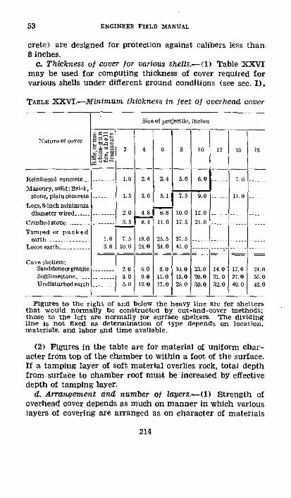
ENGINEER FIELD MANUAL
crete) are designed for protection against calibers less than8 inches.
c. Thickness of cover for various shels,-(1) Table XXVImay be used for computing thickness of cover required forvarious shells under different ground conditions (see sec. I).
TABLE XXVI.-Minimunm thickness in feet of overhead cover
Nature of cover
Reinforced concrete _Masonry, solid: Brick,
stone, plain concreteLogs, 8-inch minimum
diameter wired ....Crushedstone ...-.- -Tnamped or packedearth.........
Loose earth ....
Cave shelters:SandstoneorgroaiteSoftlimestone..Undisturbed earth
Size of projectile, inches
o° E 351 4 6 5 l0 12
1.0 2.4 3.4 5.0 .0 --
1.5 3.6 5.1 7.5 9.0
2.0 4.81 6.8 10.0 12.03.5 1. 17. 21. 0
1.0o 7.5 1s.O 25.5 37.53.0 10.0 24.0 34.0 45.0
2.0 6.0 .0 10.0 13.0 14.03.0 9.8 11.0 15.0 20.0 21.05.0 12.0 17.0 25.0 30.0 32.0
16G
711.0
15.0
17.027. 040. 0
1S
24. 036. 048.0
Figures to the right of and below the heavy line are for sheltersthat would normally be constructed by cut-and-cover methods;those to the left are normally for surface shelters. The dividingline is not fixed as determination of type depends on location,materials, and labor and time available.
(2) Figures in the table are for material of uniform char-acter from top of the chamber to within a foot of the surface.If a tamping layer of soft material overlies rock, total depthfrom. surface to chamber roof must be increased by effectivedepth of tamping layer.
d. Arrangement and number of layers.-(1) Strength ofoverhead cover depends as much on manner in which variouslayers of covering are arranged as on character of materials
214
53
---L---

FIELD FORTIFICATIONS
of which it is composed. Proper arrangement of layers isshown in figure 120.
(2) Component layers consist of the following:(a) Bursting layers must be provided for all cut-and-cover
and surface shelters and over entrances to cave shelters tocause force of the explosion to be expended upward due tolack of tamping effect. They are effective against shells withinstantaneous and short-delay fuses. The bursting layer maybe made from any of the materials listed in b above, should
' W$St- tAATH AEt10 H t GO C4CUMULAGt'
!v CO¶lfOC a-eotU T tsrttsa S IO l tSTgBA'JTt M P LAYtr'or.!- 2: D t :.:_ ' .. . .a'.a-r.
2 2,A -0 TAMOSED ARTH at. . XSKOCa ABSOR.IH1 CUSSlOS
2o'0 TA$4PtD ZflT S2:..' (VERY Ifl/ourT
; ' a..W~ ; Co ] Tir ISttlsIDIKO LArCeI
2-.. ,..,T1:0 0NTAMP:D , .. : OCK A$sOaBo. CUSNION
.a loos QIal rooeTntR I D15inH6 LSTOr~,' ."O'SROI# -. i.-.'.:.SW
T I0S OSTIB A30: KtUCAP
SHELT.STAfi6T £OUIV<tl TO?47:0 O #AQO DR viOInH ART.PAOOr AOAIHST CS IHLL
FiGrct 120.-Diagrammatic section showing name, character, and
correct manner of placing successive layers of artificial cover.
be in the form of an umbrella, and should extend to a pointwell beyond a line drawn tangent to the bottom edge of theshelter at an angle of 450 to the vertical. Bursting layersshould be covered with not more than 9 inches of earthwhich should preferably be sodded. This serves to concealthe shelter, prevents flying splinters, and reduces disintegra-tion of the burster layer by several hits in the same place.Figure 121 shows details of standard reinforced concreteburster.
215
53

53 ENGINEER FIELD MANUAL
(b) Distributing layers of logs firmly wired together, steelI-beams, rails, or concrete beams set on edge are essentialto distribute strain and to prevent penetration of shell frag-ments. These layers are placed in accordance with principlesillustrated by the example in (5) below. Weight of overhead
tade Rn lengths ofr C/t if ond 1ft.V!htf J'*erff
rear 6k:o0am bt ia rod or smirŽ
- 15'0'. - ... - ... Ie'f 2a " -- " *
Concrete Beam
I-
By ' ?~BDurster Assembly
F"r otlt4r ,
W9it. O'f , aid eora " lre
Concrete DursterGmts 121.-Standard reinforced concrete burster and beam.
cover is carried by the lowermost distributing layer whichrests on berms left in the natural soil. Thus weight of coverand shock of explosion are transmitted to these berms ratherthan to the interior framework. Details of standard rein-forced concrete beams are shown in figure 121.
216

FIELD FORTIFICATIONS
(c) Shockc-absorbing cushions are essential beneath thebursting layer, over the top of the inner framework, and be-tween the distributing layers. The one beneath the burstinglayer may be of loose or tamped earth, the others of tampedearth or broken stone, except the one immediately above theshelter which should be of tamped earth. Pacines (see par.37d) are sometimes substituted for tamped earth with satis-factory results. The omission of these shock-absorbing cush-ions is one of the most frequent causes of failure of cut-and-cover shelters. The top and bottom cushions are the mostvital and under no circumstances should they be omitted.
(3) Proper interior support is essential to secure the fullvalue of overhead cover. The clear span of the interior frame-work must not exceed 6 feet 6 inches for cut-and-cover or 8feet for cave shelters. The figures for cover are based on theuse of these spans and upon the use of standard size timbersproperly supported. If these are not used, the cover providedif based on table XXVI may be insufficient.
(4) The shock or blow of the explosion strikes the stiffdistributing layer and is spread over the cushion; the latterabsorbs part of it and further spreads its effect before it strikesthe next distributing layer, where it is again spread over awider area until finally when the blow reaches the inner shellof the shelter chamber it is so distributed and absorbed as tobe sustained without rupture.
(5) An example of the computation for cover to protectagainst 6-inch shell using several classes of material, similarto that used in figure 120, is given. It is assumed that thematerial available for cover consists of 8-inch diameter logs,standard bursters and beams, and earth, the latter to betamped or packed. With the general number and arrange-ment of layers determined, it is desired to find thicknessof earth that is to be distributed in the cover. From tableXXVI the total cover for tamped earth alone is 25.5 feet. Anyother material except loose earth reduces this figure by theratio of thickness used to thickness required if the materialwere to be used alone. Thus reinforced concrete would berequired in thickness of 3.4 feet if used alone, but, as 0.415 footonly is used in one layer of concrete bursters, the layer has a
value equivalent to '415=12.2 percent of the total thickness3.4217
53

53 ENGINEER FIELD MANUAL
for the material used alone. The following values are used inthe above manner in computation of percentage equivalenceof the whole thickness for each material used, except earth:
2 layers standard concretebeams- -_----_________.. 0.83 foot thick (or high)
1 layer standard concrete Lbursters__ .__ .________. .415 foot thick
1 layer of 8-inch diameterlogs --____---_-_____-__ .66 foot thick
Then the percent of total cover allocable to these materialsis--
PercentConcrete beams ___-. _____ (0.83-3.4) X2= 48.8Concrete bursters -_______- 0.415: 3.4= 12.2Logs ____- __-_____-_____. 0.66-:6.8- 9.7
70.7Percent of cover allocable to tamped earth -____ 29.3
100.025.5X29.3 percent=7.5 feet or three layers of 2 feet and
one of 1'/2 feet thick.e. Concrete as overhead cover.-(l) Concrete, either plain
or reinforced, is a most effective shell-resisting material.(2) There are apparent drawbacks to the use of concrete in
active warfare, but some may be more apparent than real.These drawbacks are-
(a) Too many workers concentrated in a small area.(b) Construction time is long when portland cement is
used.(c)-Cement at the front is likely to deteriorate: it is neces-
sary and difficult to keep it dry.(d) Due to interruptions, it is often impossible to obtain
a continuous pour of concrete and a truly monolithic shelter.(3) Use of high early strength cement concrete in place of
standard portland cement reduces the construction time, andis therefore especially suited to war construction because theformer attains about 75 percent of its full strength in 24 hours,against 24 days for portland cement concrete; it also permitswork at relatively lower temperatures. The final forms
218

FIELP FORTIFICATIONS
(beams, slabs, etc.) may be removed if necessary about 30hours after pouring high early strength cement concrete.
(4) Where amount of concrete to be poured is relativelylarge and other conditions, as hostile interference and obser-vation, do not control, concrete mixing should always bedone by power mixers if they can be obtained. The mixingof concrete by machinery should be made the rule even insmall batches of a few yards to reduce time of operationand number of men necessary.
(5) Construction time includes the whole period of workfrom commencement of labor to the time when the structurebecomes effective for use. The factor of transportation ofmaterials may have a delaying effect if amounts required areexcessive. Comparing shelters of equal capacity and re-sistance, necessary transportation for materials for a con-crete shelter is in most cases considerably less than for ashelter constructed of lumber, logs, rails, concrete beams, andcrushed stone.
(6) Existing conditions may cause cement to deteriorate.The ability to protect cement from deterioration increasesin proportion to the distance from the front line.
(7) Liability to interruptions in pouring increases in directproportion to proximity to the front line. The shortenedperiod of construction due to use of machinery on a well-coordinated job lessens importance of this drawback.
* 54. STANDARD CONSTRUCTION MATERIALS.-a. General.-Ex-perience has developed standard materials for use in theconstruction of protected shelters which are distributed byengineer agencies. Their use results in economy of materialand labor. The construction materials described are givenas a guide for establishing standard materials. Standardreinforced concrete beams and bursters have already beendescribed in paragraph 53 and figure 121.
b. Timbers.-Cases will often occur where round timberscut near the site will have to be used in lieu of dimensionedlumber. The following table gives a number of standardsize sawed timbers and the round timbers which should beused in lieu of them.
219
53-54

54-55 ENGINEER FIELD MANUAL
TABLE XXVII.-Equivalent timbers used as beams
Sawed Jim- Erea quivalent Areahers, width (square rdtin ,1er
X depth inches) diameter inr sL
Iby4 4 3 7.11i)y 6 9 4½ 15.9
2by4 8 4 12.62by6 12 5 19.62by8 16 6 28.32 by 10 20 7 38.53by3 9 3i 9.63hbyG 18 6 2s.33 by 10 30 8 50. 33by12 36 9 63.64 by 4 16 5 19.65 by 10 0 10 78. 56by6 36 7 38.58by8 64 10 78.58 by 12 96 13 132.78 by 14 112 14 154.08 by 16 128 15 177.0
12 by 12 144 14 154.0
Nor.-The equivalent round timbers are also safe as columns.In making up the table primary consideration was given to resist-ance to bending. However, in every case the round timber willresist more vertical shear than the timber of rectangular crosssection to which it is equivalent.
c. Corrugated steel arches-Arches are fabricated fromheavy corrugated steel (fig. 122). They are classified as toname and size as-
(1) Two-man, for splinterproof and light shelters.(2) Light elephant, for splinterproof and light shelters.(3) Elephant, for light shellproof shelter.
U 55. SURFACE.-a. From the standpoint of construction, sur-face shelters fall into the following groups:
(1) Surface shelters concealed in woods or behind reverseslopes.
(2) Shelters constructed by reinforcing buildings.(3) Reinforced concrete shelters above ground.(4) Small light shelters for protection of ammunition and
stores.220

/ VIt one4(7 \Scction ++
Crosssectior
Ec 3ato.
Eleva~tiorm
Tao Man
Cross Section Elvtiont
Light Elephartt
OS/1atYfn ackjohnt
EleptantFIGon 122.-Corrugated steel arches.
2f2375° -40-15 221

ENGINEER FIELD MANUAL
b. Surface shelters concealed in woods or behind reverseslopes.-(l) This form varies from the hasty splinterprooftype to the light shellproof type.
(2). The hasty splinterproof type is usually of an impro-vised nature built out of the materials at hand, for example,a shed built with logs and corrugated iron covered witha light layer of earth. No standard form of construction canbe specified.
(3) A form of light shelter with material list is shown infigure 123. It has a capacity of 12 men and protects against3-inch shells. Standard elephant corrugated steel (see fig.122) is used with a covering of 1 foot each of concrete andsandbags, 1,/2 feet of crushed stone, and 9 inches of tampedearth, The ends consist of wood partitions having doors,and are protected to the same extent by carrying the coveraround the ends. The bunks are made in the standard way
~ /; s Laoye Sandbags
; ~ ~ ~~7 L bikeefenere~ Iogil..,
_! _
PLANFIGcURE 123.Corrugated steel surface shelter, capacity 12 men.
222
55
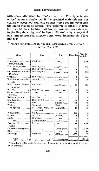
FIELD FORTIFICATIONS 55
With some alteration for roof curvature. This type is de-scribed as an example, but if the specified materials are notavailable, other material can be substituted for the cover andthe lining may be of timber. The concrete is difficult to pourbut may be done by first building the covering materials upto the line shown by x-x' in figure 123 and using a very stiffmix and improvised exterior form work immediately aboveline x-x'.
: TABLE XXVIII.--Material list, corrugated steel surfaceshelter (fig. 123)
Item
Corrugated arch se-tion, comnplete.
Post, bilnk, one cut -
Sill, feathered from 4 b0 inelles.
Sleeper ....Bulnk frame, crosswise,
3 cuts.11unk frame, length-
>ise, tolut.Batten ..........Sprag, cross, and longi-
tudinal.Nailingstrip, post. .--.End lumber ----.....Flooring ..........Wedges .......Wire netting_ _ ._- ....
Wire, bunks ...-.Staples -.. --....Nails -.....---.....
Do ...-..Cement (1-2-4 con-
crete).CrUshed stone or gravelSand ...-..-.....Sandbags ....-.....
Total -..... :
size
EleDphant .
4 by4by 13t ----......4by4by lo0 ft......4 by 10 by6t .....
Unit
Ea-ch, .
.... do.......- do
do ...
3 by 10 by lf 1 t --- I --: do,2by4 by 12 ft ----- _do ---
Standard .......-....
2x4x12 ft .......-- do ..........
2by 2by 12ft........2by6by8t -.......1 inch..Standard -....36 inches wide, 12
inch rmell.No. 12 ....
6, No ...........Tenpenny.........Twentypenny --In bags ..........
Standard
._ do-
.- do ....
.... do.,--.-
__ do.....__do.....
Quantity WeightQ (pounds)
2, 100
4 _ 2754 2153 240
4 130
12 385
64
324
Square ft 150Each ..... 2Linear ft. - 7
- do --- 320Pondo --
do --- 6
Bag _ _ 100
Cubic yard. 13-- -do ....Each. -... 1, 200
:: -. ~_L.l --
130
50-inO770;OW3020
10665
9, 800
143, 10021, 600
600
181, 142
' Incldes 15 cubic yards fir concrete. Remainder may be alternated by brick.bats if available.
223

ENGINEER FIELD MANUAL
WEIGHTS
Items Pounds Tons
Lumber....................... 3,895 1.95steel .................... . 2 100 1.05Cement ...........................-.......... 9,800 4 90Crushed stone or gravel ......-.. 143, 100 71.55Sand ..-. 21,600 10.0
-i-scel-aneous-647 ............ b7 .32
Total ........ ......---------. 181,142 90. 57
c. Shelters constructed by reinforcing buildings.-Whenprotected shelters are constructed inside of buildings theyshould generally be proof against at least 6-inch shell be-cause buildings form a favorite target for artillery. Eightfeet of artificial cover consisting of dry walls (large slabsof rock, masonry, or concrete), timbers or poles wired to-gether, and undisturbed building walls give this protection.Where possible the chamber of the shelter should be placedin an excavation below the ground level of the building andthe covering material supported on berms, in which case itbecomes a cut-and-cover type. Figure 124 shows a room ina building used as a shelter, the cover being placed on thefloor above and the floor stringers shored up. This typemay be used where conditions do not permit cut-and-coverconstruction.
d. Reinforced concrete shelters above ground.-Sheltersof this type may be used to protect personnel in relativelylarge numbers provided it is practicable to assemble thematerial necessary for construction. The design of theseshelters follows accepted practice for reinforced design sofar as placing reinforcements is concerned. Ordinarily theymay be used in connection with emplacements for protec-tion of the crew on duty at the emplacement and for obser-vation and command posts under proper conditions. Theyshould be provided with a burster course extending on allsides of the shelter to prevent penetration and explosion ofprojectiles under the structure. The whole structure shouldbe covered with sod for concealment.
224
55

FIELD FORTIFICATIONS
* 56. ARTILLERY AMMUInTIoN.-a. General.-(1) The essen-tial requirement of an ammunition shelter is that it be madewaterproof.
(2) Cover to give protection from shell fire is not essentialalthough concealment is desirable always. If overhead coverwere to be secured by depth below the surface, storage andservice of ammunition would be impracticable; if securedby building above the surface, concealment would be im-practicable.
STONE OR aCOoNCRETE SLAE6I~ LW°Ie3L~LOGS OR TIMBERSAND TIMBERS ~.bY~II~~~~~-WIRED TOGETHER
tEN-Y DD~EW~_ OLD FLOORCONSTRUCTION
6BUILDING WALL'
TRANSVERSE SECTION
- -~LOGS OR TIMBERIRED TOGETHER
LD FLOOR4%8 I-RAG I AD~A CONSTRUCTION
BUILDING WALL
GROUND LINE
LONGITUDINAL SECTION
FIGURE 124-Shelter in reinforced building.
(3) It is desirable that ammunition be stored below thelevel of surrounding ground so that if a direct hit is ob-tained destructive effect of the explosion will be minimized.In cases where ground water limits depth of excavation,irregularities in the surface of the ground are utilized toobtain a certain amount of natural cover.
(4) Amount of ammunition for which shelters are pro-vided depends on the tactical situation, the minimum being
225
56

56-57 ENGINEER FIELD MANIUAL
that amount which is normally carried in vehicles of thebattery.
b. Hasty position.--(1) In a hasty position time seldompermits construction of shelters for ammunition. Essentialrequirements are to keep ammunition dry and well concealed.
(2) It always is advisable to place some sort of platformunder ammunition. If this is not done the location shouldbe drained. The platform is made of brush, logs, planks, orsimilar material, and the piles covered with paulins or impro-vised material.
c. Deliberate position.-(1) In a deliberate position advan-tage is also taken of the materials available locally. Ammu-nition shelters do not require elaborate construction, andthose shown in the figures 125 and 126 illustrate types thatmay be used.
(2) The shelters are located in rear of the piece or at somefavorable point on the flank. Shelter for some ammunitionis constructed at the emplacement. Additional shelters areconstructed farther in rear for a reserve supply. Shell,powder charges, and fuses always are stored in separateplaces. For separate-loading ammunition the shelter forshell preferably is located to the left of the emplacement.
(3) Types.-(a) A corrugated steel arch shelter erected inthe side of a trench is illustrated in figure 125. This shelterholds 50 rounds of ammunition or 8 boxes of fuses.
(b) Elephant steel shelters preferably are used for storing155-mm or larger shell. These are waterproof, easy to erect,and the materials for them usually available. They are builtto any size by increasing number of sections. The height issufficient to enable a man to move around freely inside. Theconstruction of an elephant steel shelter for 155-mm ammu-nition is illustrated in figure 126.
U 57. CUT-AND-COVER.--a. Excavation for cut-and-cover shel-ters reaches practical limits at a depth of cut of about 12 feetbelow the surface. All shelters with a base to be placed lowerthan this should be constructed by mining methods (caveshelters).
b. Splinterproof.-(1) One of the simplest forms ofsplinterproof cut-and-cover shelters for use in mobile warfareis shown in figure 127. This type is frequently constructed
226

FIELD FORTIFICATIONS 57
by the infantry soldier in the advanced lines. He must betrained in performing the task as his natural tendency isto dig a niche in the forward interior slope of the trenchwhich is the proper location for the shelter, but the result
-P/r/cs ororr-oteo -
iNote: S TP/oce thin boards or brash bewen /loers of
/he/ or p/oce o/terote /a4ers with base andpoint to front
Tpzo of Poreoetfz
I . 50 '---- t
' D0CbOrdEL/VATION
FIGURE 125-Corrugated steel arch shelter for 75-mm ammunition.
is an unsupported recess which quickly caves under effect ofshell fire and weather conditions.
(2) Construction.-An open excavation is made closely fol-lowing dimensions given in figure 127. The ceiling shouldbe at ground level or slightly below, and the logs rest on
227

57 ENGINEER FIELD MANUAL
LONV TDO/ruNAL S$C7TV
(NO &LfVA r ON
FIcunE 126.--Elephant steel shelter for 155-mm ammunition.
228
-~""""""';`-:: 1 ~~""'w- ;" ;,

FIELD FORTIFICATIONS
berms of virgin earth which should be at least 18 incheswide. Logs should be not less than 6 inches in diameter andfirmly wired together. Earth is then backfilled and originalappearance of the parapet restored. The shelter may bemade waterproof by the use of corrugated iron or tar paper.
Y-tra pfs~l
-soZOontom ?f Trnch -
Section t Elevation
FiouRE 127,-Splinterproof shelter.
TABLE XXIX.-Material list, splinterproof shelter (fig. 127)
Item Size Unit Quantity W5ngb
Logs, roof... 6-inch diameter by 8 Each ... 13 1,feet.
Wire ---------- No. 12 Linear foot 100 3Sandbags ...-........ Standard .....-.... Eaech.... 30 15
Total weight ... 1,018
(3) Steel arch.--The two lighter types (two-man and lightelephant) of corrugated steel arch shown in figure 122 areespecially useful in consolidating captured trenches after anattack in trench warfare. Splinterproof cover can be obtainedrapidly by placing several sections in captured trenches soas to form a tunnel and shoveling earth on top and sides.At least 4 feet of loose earth cover should be provided.
c. Light shelters.-(1) Types of light shelters proof against3-inch shells with material list included are shown in figures128 and 129, and tables XXX and XXXI. These may be ofeither cut-and-cover or cave construction depending on soilconditions.
229
57
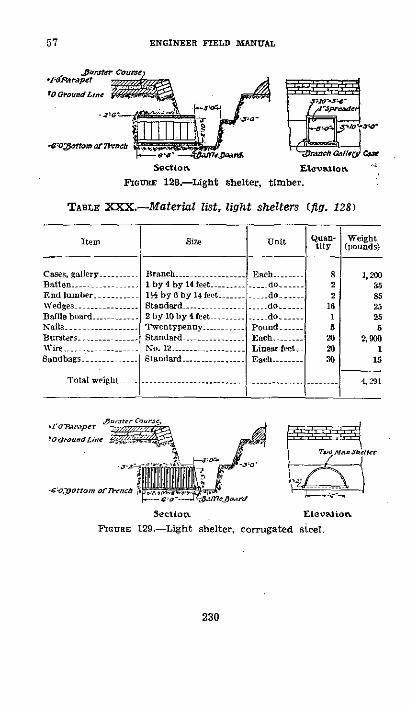
ENGINEER FIELD MANUAL
Jat-ster couru.XteAcrae, t.f
tO Gt~und Line -
O1;gpamat cg.: ro~oaor1 rWc
a -$ entet Tofh C/ca rvs CSectiot Eatevatlo
nourEs 128.-Lght shelter, timber.
light shelters (fig. 128)
Item Size
Cases, gallery ..... Branch....Batten - -............ 1 by 4 by 14 eet...End lumber ..--....- 1 by 6by 14 feetWedges --............- - Standard....Baffle board.......... 2 by 10 by 4 feetNails ........--....-.. Twentypey ........Bursters ..........- Standard..........Wir - -............ No. 12........ .....Sandbags .......... .. tandard
Total weight ll
Each....
_ _do......... do.-....... do.-..-..PoundEach .....Linear lfeetEach----
Quan-tiry
822
1616
202030
Weight(pounds)
1,200358525255
2, 9001
15
4 291
!O ound LU,,e
-c "orttom ornmeA
Sectlo.n .levietio,
F`Guns 129-Light shelter, corrugated steel.
230
TABLE XXX.-Material list,
57

FIELD FORTIFICATIONS 57
TABLE XXXI.-Material list, light shelter (fig. 129)
Item Size Unit Quan- Weighttity (pounds)
Floor -- _ ------ 3 by 10 by 6 feet - -= Eact- -- 6 360End ....--.......... do -.......---- (1do .:__ 3 180Baffe board .........- 2 by 10 by 6feet ....... do ..... 1 40Floorstrips..... 1 by 2 by 12 feet .. -- do ...Corrugated arches_ _ Two-man- -...... .... do..... 3 132Nails ...... Twenty penny ...-... Pound...... 2 2Bursters ........ Standard .......... -Each ..... 20 2,900Wire ........ No. 12 ...........- Linear foot.. 20 1Sandbags ............ Standard...........- Each 30 15
Total weight -.... ...................... . 3, 38
- (2) Construction.-In firm soil these types usually can beconstructed by digging into the face of the trench withoutcutting all the way to the surface of the ground. In loosesoil it is necessary to make an open excavation and backfill.Both types of shelter must closely fit the excavation which isaccomplished by cutting the excavation accurately to size andby ramming dirt into any space outside the frame. The floorshould slope slightly toward the trench to provide drainage,and a baffle board to exclude water entering from the trenchshould be placed as indicated in the figure. The burstercourse is placed by excavating a portion of the parapet, placingthe course, and backfilling so that original appearance of theparapet is restored.
d. Light shellproof shelters.-(I) Classes.-Cut-and-covershelters of the light shellproof type are grouped into threeclasses, according to manner of interior construction.
(a) Timbered shelters may be constructed by using stand-ard materials sent forward from engineer supply points or ofround timbers procured near the site.
(b) Standard corrugated steel arches are quickly and easilyassembled and are recommended for interior construction ofcut-and-cover shelters whenever they can be obtained. Cor-rugated steel sections when bolted together form watertightarched support.
231

ENGINEER FIELD MANUAL
(c) Concrete shelters should be constructed with reinforce-ment to obtain economy of cement and aggregates. Whentime, labor, material, and transportation are available, theyoffer superior facilities from the standpoint of protection, liv-ing conditions, and adaptability.
LONGIRINAL SEGTION
TRANMSR SECTIMON
FIGuRE 130.-Cut-and-cover, timber shelter.
(2) Cover.-Type and thickness of cover required for a cut-and-cover shelter depend on kind of material available andon location and use to be made of the shelter. Protection isprovided as described in paragraph 53 which gives thicknessof cover and arrangement of the successive layers.
232
57
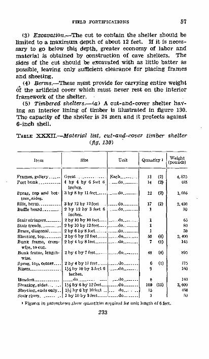
FIELD FORTIFICATIONS
(3) Excavation.-The cut to contain the shelter should belimited to a maximum depth of about 12 feet. If it is neces-sary to go below this depth, greater economy of labor andmaterial is obtained by construction of cave shelters. Thesides of the cut should be excavated with as little batter aspossible, leaving only sufficient clearance for placing framesand sheeting.
(4) Berms.-These must provide for carrying entire weight6f the artificial cover which must never rest on the interiorframework of the shelter.
(5) Timbered shelters-(a) A cut-and-cover shelter hav-ing an interior lining of timber is illustrated in figure 130.The capacity of the shelter is 24 men and it protects against6-inch shell.
TABLE XXXI -Material list, cut-and-cover timber shelter(fig. 130)
Item
Frames, gallery.....Post bunk .....-...
Sprag, top and bot-tom, sides.
Sills, berm ...-....-Baffle board ...-...
Stair stringers ....-..Stair tteads..Brace, diagonal....Sheeting, top........Bunk frame, eross-
wise, to cut.Bunk frame, length-
wise.Sprag, top, center.-Risers -.....-.--------
Headers .......---------..Sheeting, sides ....Sheeting, ends only.Stair risers..
Size
Great...........4 by 4 by 6 feet 2
inches.3 by S by t1 feet....
3 by 12 by 12feet -2 by 12 by 3 feet 6
inches.2 by 10 by 10 feet.2 by 10 by 12 feet.-2hy6by8feet --2 by 6 by 12 feet2 by 4 by 8 feet---
Unit Quantity
-arh 11 (2I.. do ....
.. do - --
..... do..- do........
do........do
2 by 4 by 7 feet ......... do......
2 by 4 by 11 feet ....-... do.....1A by 10 by 3 feet 6 ... do ...-..
Inches.do ........... do..
1I by 6 by 12 feet.. do1 by 6 by 10 feet ..... do .....1 by 10 by 3 feet .---- ...do ...--
14
12
171
111
50
6980
2
100153
(2)
(2)
(2)
(8)(1)
(8)
(1)
(15)
i Figures in parentheses show quantities required for unit length of 6 feet.
233
Weight(pounds)
4, 875485
1,055
2, 45030
658030
2, 400145
895
175160
1403, 600
45030
57

57 ENGINEER FIELD MANtUAL
TABLE XXXII.-Material list cut-and-cover timber shelter(fig. 130)-Continued
Item
Batten.......Revetting boards, to
cut.Wedges ........- .Cases, gallery .....Flooring .........Corrugated iron, gal-
vanized.Wire netting......
Wire, hunks ----Staples -. --Nails ..........---
Do .. ,Do...
Sandbags.......Bursters ...Wire, binding .Beams, concrete ...-Logs ...........Crushed stone, if
used.
Total weight.__
Size Unit
by 6 by 10 feet d...... do ... do
Standard ---...........- doComnmo..n-.... doI inch Su....-.. . iare footNo. 20, 8 feet by 24 Sheet -........
inclies.30 inches wide, 2- Linear foot -.
inch mesh.No. 12..... ..-- --- do ....--%, No. 9 ....... Pound ...-
Fortypenny ......... doTTwentypenouY -- - do ....Tepenny ------ do...Staodard ........- Each ....
.. do ....-.. do ..No. 12 ...-....... Linear footo__Standard... dS-inch diameter - do
-..................: Cubic yard_
…
1 Figures in parentheses show quantities required for unit length of 6 feet.
WEIGHTS
Item
L.umher .....Concrete beams and bursters - --------- - --------Logs -,-,-,-,-,-,-,-,-,-,-,-,-,--- ----Crushed Stone .........------------ -- ----------------Mliseellaneous ........... ----- -----...---
Total weight ......................
Pounds
23.905237, 95050.400
810,000952
1.123,207
234
Quantity t
(20)
(15)(4)
(26)
(80o)(2)
104
184279021
156
480121220101too
7503.5003,4003, 00
Weight(pounds)
20080
2605,940
360691
40
1212
20
10108, 750
tOS129, 200
50.400810,00)
1.12, 207
(2)(8)(2)
(88)(400)(gW)(380)
(20)
Tons
11.9511897
25. 20405.00
.48
561.00

FIELD FORTIFICATIONS
(b) The maximum spacing of frames is 3 feet, but wheretimber is available the spacing should be at 2-feet centers.The maximum span should not exceed 6 feet 6 inches,Where exceptional strength is more essential than largecapacity, shorter spans should be used. All frames must bebraced with distance pieces both at the top and bottom at thesides and at the top in'the center. The sprags must be placedto bear both on the posts and on the caps or sills as the case
,may be.
) Long boards i nstead of standard sheeting should beo 131.-ut-ad-coverrrugde
used in sheeting this type. The boards should be given fullbearing on the posts, and the joints should be staggered.Nails should be used where possible. With standard sheetingoverlap to the full width of the frame to get full bearing.Corrugated iron is placed on top of the chamber, and sidegutters are fastened to the outside as indicated in the figure.These may be of corrugated iron or of wood. They lead tosumps in the trenches as shown by the dotted line,
23523.t
57
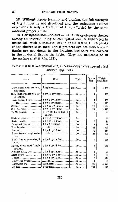
57 ENGINEER FIELD MANUAL
(d) Without proper framing and bracing, the full strengthof the timber is not developed and the resistance againstexplosions is only a fraction of that afforded by the samematerial properly used.
(6) Corrugated steel shelters -(a) A cut-and-cover shelterhaving an interior lining of corrugated steel is illustrated infigure 131, with a material list in table XXXIII. Capacityof the shelter is 24 men, and it protects against 6-inch shell:Bunks are not shown in the drawing, but they are coveredin the material list in the table. They are arranged as inthe surface shelter (fig. 123).
TABLE XXXII.-Material list, cut-and-cover corrugated steelshelter (fig. 131)
Item
Corrucated arch section,complete.
Sill, leathered ron 4 by10 inches.
Post, bunk, 1 cut ..
Sleepe ........Sills for rails ...Baffle boards ....-..
Stair tnringers......------..Stair treads .Diagonal braces .......End lumber...........Batten.........Bunk frame, lengthwise
to cut.Bunk frame, crosswise, 3
cuts.Sprag, cross and longi.
tudinal.Nailingstrip, pos t...Stair risersBattenl........Bevetting boards......Cases, gallery .........Wedges .............
Size Unit
Elephant...........
i by 10 by 6 feet...
4 by 4 by 13 Lset4 by 4 by 10 feet ...3 by 10 by 11 feet.....
byl0 by 12 feet _2 by 12 by 3 feet 6
inches.2 by 10 by l ftet-2 by 10 by 6 feet -.-2 by6 by8 feet ........... do.......2 by 4 by 12 feet....
Each .....
..... do.
do.....-- do ....
i. do.
-- - do- .-do
--do -------- do ........ do.....
I by 6 by 1o fest--....... do.
2 by 4 by 12 feet.....
2 by 2 by 12 feet... -I by 10 by 3 feet ...I by 6 by 10 feet........ do.............Common .............Standard- ....
.... do ....
.... do......... do..... do ...... Ldo........ do........... do ------
QuAn.tity
14
6
77
15241
21
241224
7
8
637
21124
Weight(pounds)
4,200
480
485375
1.6502, 880
30
65so30
770385770
225
255
9530
140
4,620175
236

FIELD FORTIFICATIONS 57
TABLE XXXIII.--Material list, cut-and-cover corrugated steelshelter (fig. 131)---Continued
Item Size
Nails- --.---------- Twetyleony .....Do e....... l Te penny
Staples, bunks- .-.... inoh, No 9......iWire netting, bunks 36 inches wide, 2-inch
mesh.Wire, hunks ..-.....- - No. 12 ......Wire, binding ............. do.......Bursters ........... Standard .......Rails, railroad ..- . 15 feet at 75 pounds
Rails, railroad, variedlengths,
Sandbags ............Cement, Lor floor iflued.Sand, for lowr if used_...Crushed stone. fIor floor
if roed.Crushed stone, or gravel,
fill.Total weight
(yard).At 75 pounds (yard) --
Standard-------------
Unit
Pound... do
.__ do....Linear eet-
- do-do
Each ,do ..--
Linear feet_
Each....Bag --------Cubic yard
do.......g
Quan- WVeightthiy pounds
15 1515 1512 . 12
156 40
640 204,000 1204, tO 170
. 0 108, 750172 64, 500
80W 22,000
100 5036 3, 5283 8.1007 s8, 9o
250 075, 000
918, 870
WEIGHTS
Item Pounds Tons
I.umber. 13.20 6.81Rasia53 -S, 500 43. 25Cement - .. 3.................-...1....3, 528 1.76Sand -_1.....................0-.. .. 8I 00 4.065Crushed stone or gravel ..........-............ - 693.900 346.95Steel arches ------------- ---- -------- - - __ . .. ---. ....... 4, 200 2.10Bursters ---- -------------------- - ..... --- 108,750 54. 38Miscellaneous 7.................. - 72 .14
Total weight - --------............... ........ ---- 918,80 45944
(b) In construction care should be taken that the founda-tion is firm and that the arches are not spread at the bottom,thus causing a depression at the top of the arch which mate-rially weakens it and forms joints through which water may
262375°--40-16
-I --------
237

ENGINEER FIELD MANUAL
·,~~~~~~~~~~~~~~~~~~~~~~~~~C
I O;
~~~~~~~~~I jj3 ¾""R-
I~W dl h
over s or-
i ORaei6 i ( :o
238
A:
I

FIELD FORTIFICATIONS 57
seep. If a concrete floor is provided it should be about 6inches thick.
e. Heavy shellproof reinforced concrete shelter.-(1) Mostreinforced concrete shelters are of the cut-and-cover type.Use of large concrete shelters is generally limited to reservepositions in stabilized situations.
TABLE XXXIV.-Material list, brigade command post(fig. 132)
Item Unit Quantity Weight(tons)
Cement, 1:2: 4 concrete (450 cubic Bags ( cubic foot) 2,700 135yards concrete).
Sand ..-................ Cubic yards-.. -200 270Crsbhed stone ..-.......-... -o ..-... . ... .400 540Reinforcing metal .. Pounds ..... 40, 20Bunters- .-------..... Each -1.L.. 600L 116Lumber forms --. Foot b. m... 2, 400 5
Total weight ................. .... 1,086
(2) Figure 132 illustrates a brigade command post of rein-forced concrete proof against 8-inch shells. It is not givenas a standard but as an example. Note particularly methodof reinforcement. Grillage of bars on 6-inch centers isusually of %-inch rods. Reinforcement spaced at greaterdistance is of larger size up to 3/a inch. On the inside ofthe chamber a layer of expanded metal or similar fabric isplaced for added protection against spalls. It is better tohave a large number of rods of small diameter than a smallnumber of large diameter. The weight of reinforcement runsabout 5 pounds per cubic foot of concrete.
(3) The structure may be built without any cover, butcover with a burster course should be added if possible tolocalize action of a bursting shell. The figure shows coverwith a course of bursters.
(4) Approximate quantities for the command post illus-trated are shown in the material list.
239

57-58 ENGINEER FIELD MANUAL
(5) For floor space requirements of command posts seeparagraph 64. For other types of command posts see para-graphs 39e and 58f.
D 58. CAvE.-a. Standard construction materials.-(1) Cases,gallery, and shaft.-(a) Cases are designed as a lining, with-out additional material for use in horizontal galleries, in-clined passages, and in shafts driven underground by miningmethods (note that frames in (2) below, require sheeting inaddition). Dimensions of lumber used in cases vary withsize of gallery or shaft (tables XXXV and XXXVI). In hori-zontal and inclined passages the cases are ordinarily placedin a vertical position and in shafts they are always horizontal.The standard common gallery case using dimensioned lumber,and improvised shaft case using round timbers are shown infigures 133 and 134.
(b) The great gallery case finds little use except in theapplication to special approaches or passages as in the first-aid shelters. When used in this way the cases may be nar-rowed to any width desired for economy in excavation with-out sacrifice of space. The common gallery case is normallyused in inclined entrances driven with cases (b (3) (d) below),and in galleries when driven with cases. The use of thebranch gallery case provides for construction of the timberedlight shelter shown in figure 128. It also fulfills the require-ment for ventilation shafts in cave shelters. The half andbranch gallery cases serve for machine-gun shafts, for emer-gency exits, or for access to observation posts.
(2) Frames, chamber, gallery, and shaft-(a) Standardtypes of frames are shown in figure 135. They are used inhorizontal or inclined passages or in shafts to support accom-panying sheeting which forms the lining of the passage orshaft. For use in shafts all timbers of a frame should be thesame size as given for frame posts. Dimensions are such asto permit a frame spacing of not over 4 feet on centers.When dimension lumber is not available frames can be im-provised from round timber.
(b) The chamber frame is designed for use in the roomsor chambers of cave shelters. The posts may be furnishedin 6- by 6-inch dimension timber or round logs at least 6inches in diameter at the small end. If the latter are used,
240

FIELD FORTIFICATIONS
they must be straight and as free from knots as possible.Caps are 3- by 5-inch steel I-beams 9 feet long, weighing9% pounds per foot. They are held on the posts by standardbeam shoes fastened to the posts by spikes or lag screws.
Common GaLeryt Case Improvised Qatlery CaseFounRE 133.-Gallery cases.
Plan Ionme ricc
Vide Elevation Corner DetailIcurE 134.-Improvised shaft case.
A 2-inch notch is cut in the floor to receive the bottom of thepost. In soft ground foot blocks of 3- by 10-inch plank 18inches long are placed under the posts. In very soft groundsuch as clay the bottoms of the posts should be sunk from
241
58
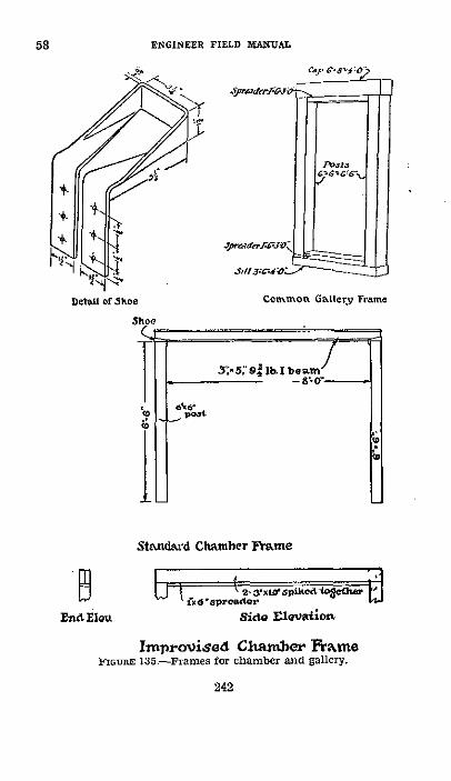
58 ENGINEER FIELD MANUAL
Detail of khoe Common Gallery Frame
Standard Chamber Frame
En ElvEnd MOV..
1s 61 .zx winikoeS h 0Side ElSeaionSide Elevation.
Improvised Chamber FrameFIGURE 135.-Frames for chamber and gallery.
242

FIELD FORTIFICATIONS
4 to 6 inches into the floor. If steel I-beams are not avail-able 6- by 10-inch timber or two 3- by 10-inch planks spikedtogether may be used for the cap.
(3) Dimensions of standard galleries and shajts.-Thefollowing tables give sizes of the various classes of galleriesand shafts driven underground by mining methods andinclude material lists for cases and frames of these classes.
TABLE XXXV.-Dimensions of standard timbered galleries
Size of galleryInside clear
Height width
Fe l mInchs led InchesChamber ....-................... 6 4 8 0Great .-................ 6 4 6 6Common ................ 6 4 a 0
alf ..-............... 4 6 3 0Brancb ................ 2 10 3 0Small branch........ 2 4 2 0
TABLE XXXVI.-Material list, gallery and shaft cases
Item Greast
Cal -. --
Sill... -.
Post ....
Spreader -
Nails Ipolnds.
Weightpounds.
1- by 10 by7 feet 2inches.
.1 by 10 by7 feet 2inches.
2-1 by 10 by6 feet 6inchIs.
2 hby IOby6 feet 6inches.
. tenpenny
385 .-.-.
Common
1-3 by 10 by3 feet 6inches.
1-3 by 10 by3 feet 6inches.
2 3 by 10 by6 feet 6inches.
2-1 by 10 by3 feet 0inches.
i tenipenny.
_ 220 ........
Half Branch
1-3 by 10 by3 feet 6inches.
1-3 by 10 by3 feet 6inches.
2-3 by 10 by4 feet 8inches.
2-1 by 10 by3 feet 0inches.
I tenpcnny.
1 ...-.....
1-3 by 10 by3 feet 6inches.
1-3 by l0 by
Smallbranch
1-2 by 10 by2 feet 4inches.
1-2 by 10 by3 fact 6 2 feet 4inches. inches.
2-3 by 10 by 2- by 10 by3 feet 0 2 feet 6inches. inches.
21 by 10 by 2-1 by 10 hy3 fcet ( 2 feet 0inches. inches.
m tenmpnny. / tenponCny
I 150 .-.... I75.
I Nails for spreaders only.
243
58
--

ENGINEER FIELD MANUAL
TABLE XXXVII.--Material list, gallery and shaft frames
It Chanmber Ch amberIteam galIery gallery
Cap, I-beam i..
Beam shoe ._-
Cap ....
Sill . l--
Post.......
Spreader --
Nails 'poundsWeight -_do ...
1-3 by 5 by 9feel 0 inchs.
2 standard .
2-6 by 6 by 6feet inches.
3 G - --- --
2-3 by 10 by 9feet Oinchos.
1-4 by 6 by 0feet 0 inches.
2-6 by 6 by 6feet 6inhebs.
2-1 by6by8feet 0 inbehs.
0.4 lb. 10.-440..
Great Comanilgallery gallery
1- by 9 by 7 1-6 by 8 by 4feet 6biohos.
1-4 by 6 by ?feet 6 inches.
2-6 by 6 by 6fet Sinchbes.
2-1 by 6 by 6flet 6inches.
0.4 lb. 10d -.375.
feet 0 inehes.;1-3 by 6 by 4
feet inches.2-6 by 6 by 6
feet 6inches.2-1 by 6 by 3
feet Oinhebs.0.2 lb. 10d.255.
ItcRl
Cap........
Sill ........ -
Post..
SPreader -.-...-.....
Nails l o...... ouds__Weight .... do_
lialfgallery I Branch gallery
I-6 by 6 by 4 feeto inches.
1-3 by 6 by 4 feetO inches.
2-6 by 6 by 4 feet8 inches.
2-1 by 6 by 3 feet0 inlchs.
0.2 lb. 10d ----1!15 .... _._..
1-4 by 6 by 3 feet8 inches.
1-3 by 4 by 3 feet8 inches.
2-4 by 4 by 3 feet0 inches.
2-1 by 4 by 3 feeto inches.
0.2 lb. led ........S-.021h.1fi
I Nails Ior spcalers only.
(4) Standard sheeting.-Sheeting is used for supportingthe ground between frames in chambers and galleries and ininclines and shafts where frames rather than cases are used.Two-inch sheeting is furnished for the roof and l/2-inch forthe sides. It is normally made in 5-foot lengths designed foruse where frame spacing is not over 4 feet center to center,varying from 4 to 10 inches in width. For frame spacing of3 feet center to center, 4-foot lengths of sheeting afford econ-omy of material and work. Boards selected from the sidesheeting should be used for head boards and stair risers which
244
Small branchgallery
feet
feet
feet
feet
1-3 by 4 by 26 inches.
1-3 by 3 by 26 inches.
2-3 by 3 by 26 inches.
2-1 by 3 by 20 inches.
02 lb, 101.35.
58
i

FIELD FORTIFICATIONS
are 1/2 by 10 inches by 3 feet 6 inches in stepped inclines.If standard sheeting is not available and ground conditionsare favorable, round poles 2/2 inches in diameter at the buttand 4 to 5 feet long may be used instead.
(5) Wedges.-Wedges are used for bracing timbers tightlyagainst the walls and roofs of excavation, holding them inplace until settling of the ground has rendered displacementimpossible. Wedges must be provided in large quantities andused freely. Dimensions of the wedge are shown in figure 136.
(6) Buank posts.-Bunk posts are 4 by 4 inches and 2 by 4inches, and are used for supporting the double tier of bunksin shelters. The 4 by 4's should be placed under the caps ofthe frames, thus providing additional support. In casestandard materials are not available, round timber 4 inchesin diameter at the small end may be substituted.
1.dedeFIoU.R 136-Standard wedge.
(7) Use of lumber.--Commercial lumber cut to properlengths is used for props, bunks, gas curtain frames, bat-tens for holding timbers in place during construction, andfor strapping incline and shaft sets together, making bombrecesses, baffle boards, etc. Scrap lumber obtained duringcutting should be used in conjunction with wedges for block-ing timbers in place.
b. Construction methods.-(l) Excavation.-In earth thepick and shovel are used to make the excavation with the aidof such accessory tools as crowbars and pick mattocks. Inadvancing an incline or gallery, care should be taken not toopen up more ground than is necessary to accommodate thetimbering. Methods of rock excavation are not discussedhere for the reason that shelter construction in rock is un-usual.
(2) Removal of excavated material-(a) In small headingsthe excavated material or "spoil" is removed from the work-
245.
58
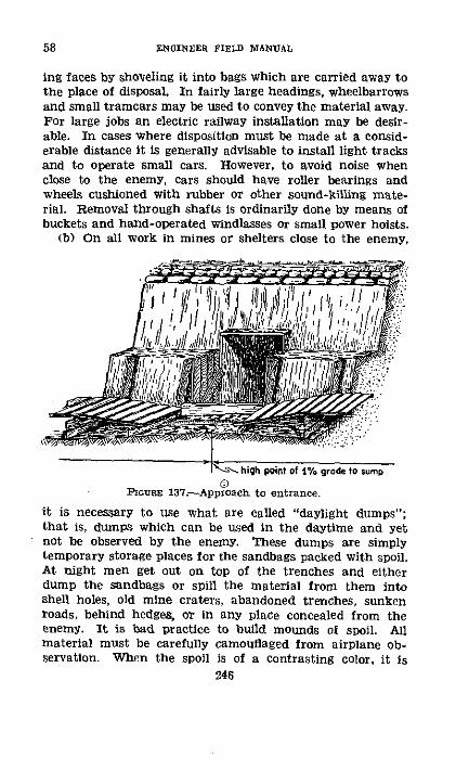
58 ENGINEER FIELD MANU1AL
ing faces by shoveling it into bags which are carried away tothe place of disposal In fairly large headings, wheelbarrowsand small tramcars may be used to convey the material away.For large jobs an electric railway installation may be desir-able. In cases where disposition must be made at a consid-erable distance it is generally advisable to install light tracksand to operate small cars. However, to avoid noise whenclose to the enemy, cars should have roller bearings andwheels cushioned with rubber or other sound-killing mate-rial. Removal through shafts is ordinarily done by means ofbuckets and hand-operated windlasses or small power hoists.
(b) On all work in mines or shelters close to the enemy,
l~ j /' 1 /0 II ,..
- -high point of 1-7 gade to sump
PiCuas 137.-Approach to entrance.
it is necessary to use what are called "daylight dumps";that is, dumps which can be used in the daytime and yetnot be observed by the enemy. These dumps are simplytemporary storage places for the sandbags packed with spoil.At night men get out on top of the trenches and eitherdump the sandbags or spill the material from them intoshell holes, old mine craters, abandoned trenches, sunkenroads, behind hedges, or in any place concealed from theenemy. It is bad practice to build mounds of spoil. Allmaterial must be carefully camouflaged from airplane ob-servation. When the spoil is of a contrasting color, it is
246
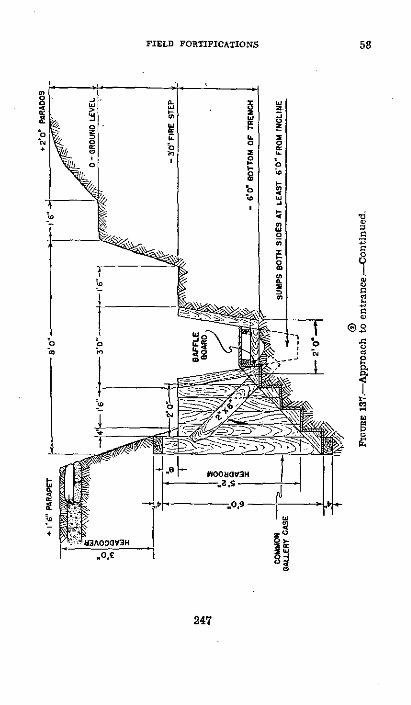
FIELD FORTIFICATIONS 58
- I
is
t i
w~~
< t G 8 O- 20
0,q Ia e
IaH 2C
_. I. S
247
-0
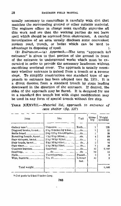
58 ENGINEER FIELD MANUAL
usually necessary to camouflage it carefully with dirt thatmatches the surrounding ground or other suitable material.The engineer officer in charge must carefully supervise allthis work and see that the working parties do not leavespoil which should be screened from observation. A carefulinvestigation of an area usually discloses some convenientsunken road, trench, or hedge which can be used toadvantage in disposing of spoil.
(3) Entrances.-(a) Approach.-The term "approach tolentrance" is given to that portion of the ground in frontof the entrance to underground works which must be ex-cavated in order to provide the necessary headroom withoutsacrificing overhead cover. The approach is usually neces-sary whether entrance is gained from a trench or a reverseslope. To simplify construction one standard type of ap-proach to entrance has been adopted (see fig. 137). It isa direct descent from a standard trench by steps leadingdownward in the direction of the entrance. If desired, thesides of the approach may be flared. It is designed for usein a standard fire trench but with slight modification maybe used in any form of special trench without fire step.
TABLE XXXVIII.--Material list, approach to entrance ofcave shelter (fig. 137)
Itern Sie U-nit Quan- Weightcity (pounds)
Gallery case l-. Common - ........... Each I1 2ToDiagonal braces, to cut_. 2 by 6 inehes by 8 feet - do. 1 32Baffle board .- .... 2 by 12 by 3 feet 6 inches_ -- do 28Revetting boards, to cut. 1 by by 10 feet...... .do. 4 80soStair stringers, to cut 2 by 10 by 10 feet do 1 60Stair treads, to cut.._Stair risers ........Concrete bursters.....Sandbags .........Nails - -.................Wire, bursters ............
2 by 10 by feet-1 by 10 by 3 feet......Standard . ...
-do....Twentypenny......No. 12 .......
Total weight ..-............
-- do -do
.- do --Pound__Linear
feet.
23
42103
40
iO30
09015a2
6, 646
I Cut posts to 6 feet 2 inches long.
248
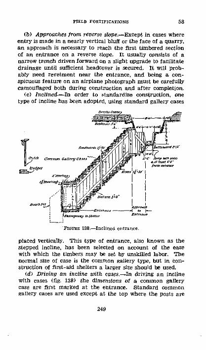
FIELD FORTIFICATIONS
(b) Approaches from reverse slope.-Except in cases whereentry is made in a nearly vertical bluff or the face of a quarry,an approach is necessary to reach the first timbered sectionof an entrance on a reverse slope. It usually consists of anarrow trench driven forward on a slight upgrade to facilitatedrainage until sufficient headcover is secured. It will prob-ably need revetment near the entrance, and being a con-spicuous feature on an airplane photograph must be carefullycamouflaged both during construction and after completion.
(c) Inclined.-In order to standardize construction, onetype of incline has been adopted, using standard gallery cases
Jk sefu~ e~ Stolter tptrlnc
FarX 138sr-Inclined entrance.
placed vertically. This type of entrance, also known as thestepped incline, has been selected on account of the easewith which the timbers may be set by unskilled labor. Thenormal size of case is the common gallery type, but in ion-struction of first-aid shelters a larger size should be used.
(d) Driving an incline with cases.-In driving an inclinewith cases (fig. 138) the dimensions of a common gallerycase are first marked at the entrance. Standard commongallery cases are used except at the top where the posts are
249
58

58 ENGINEER FIELD MANUAL
sawed to a length of 6 feet 2 inches instead of 6 feet 6 inches.This gives headroom of 5 feet 2 inches.
The excavation is carried horizontally for the length oftwo cases when the stepped incline is commenced. Excava-tion for the sill of each succeeding case is lowered 10 inches,providing for the steps. Cases are put in position as describedabove, except that headboards and risers are nailed in positionto prevent the earth from caving in between successive caps,and sills.
Attempt should never be made to excavate ahead for severalcases to be timbered later. This endangers the lives of thoseworking, and if the face or sides begin to "run" involves animmense amount of labor and leaves a weak entrance.
In very loose and caving soil the cap must be put in positionfirst and supported while the grooves for the ground sill andposts are excavated, for which purpose two "crutches" (fig.138) are used. A crutch consists of an upright piece of timbercarrying a crosspiece the length of which is equal to thewidth of two cases. The upright piece rests upon the groundsill of a case already placed and is raised to proper heightby wedges. The part of the crosspiece which projects inadvance is made 2 inches higher than the rear part to supportthe cap somewhat above its final level, and allow the poststo be easily inserted. The rear part of the crosspiece isattached to the upright by an iron rod or short chain. Whenthe case is set and adjusted to position, the crutches are takendown by removing the wedges and are replaced under thenext cap.
Each case should be temporarily tied back to the previousone immediately upon being put in, at top and bottom, bymeans of a short length of sheeting to be later replaced by1- by 6-inch battens.
The estimate of cases required for a 45' incline for any depthequals the vertical depth in inches between landings dividedby 10, plus 1. The estimate of cases for a 31° incline suitablefor a first-aid shelter entrance equals twice the difference infeet in elevation between landings. This slope provides for astairway of 6-inch risers and 10-inch treads.
(e) Sinking a shaft with cases.-Shafts are usually sunkwith cases (see fig. 134). A shaft case of the required size
250

FIELD FORTIFICATIONS
is put together and accurately placed on the site of the shaft,the dimensions of which are marked on the ground outside it.The case is then removed and the earth excavated to the depthof the case which is placed in the excavation with its top flushwith the surface of the ground. Its position is carefully veri-fied and it is secured in position by packing earth around it.The excavation is then continued for the depth of anothercase which is put in place as follows:
One end piece is placed in position, the two sides are engagedwith the end and pushed back into position; a pocket-shapedexcavation is made beyond the end of one of the side piecesand running back 3 or 4 inches into the side wall; the remain-ing end piece is inserted in this cavity far enough to allow itsopposite end to slip over the side and fall into place by drawingagainst the side pieces. The case may be toenailed and fast-ened to the higher one by short battens.
The next case is placed in the same way, care being takennot to excavate two consecutive pockets in the same corner.It is well to fill up these pockets by stuffing in from belowbefore placing the next case.
Upon reaching the level of the top of the gallery the pieceson the gallery side of the shaft are omitted if the ground isfirm, but if it needs support these pieces are put in place andsecured by cleats or braces.
(f) Sinking a shaft with frames and sheeting.-In sinkinga shaft with frames and sheeting (fig. 139), the size and posi-tion having been fixed, the top frame is laid down andstaked in place, with scores on the end pieces accurately inthe desired position. The excavation of the shaft is then be-gun, making it enough larger than the top frame to take thesheeting all around. Usually the first interval can be dugwithout driving the sheeting. It is undercut so that at thelevel of the second frame it will be larger in each directionthan at the top by twice the thickness of the sheeting. Gagerods cut to the length and width of the excavation and plainlymarked at the middle points should be provided. The incon-venience of working under the top frame may be avoided bymarking the sides carefully and digging the first intervalbefore setting the top frame.
251
58

ENGINEER FIELD MANIUAL
EGlomE 139.-Shaft with frames and sheeting.
252
58

FIELD FORTIFICATIONS
When the shaft is deep enough the second frame is put inplace and nailed together. The top and second frame areconnected by nailing to them four battens of proper length(two on each side) (fig. 139), which suspend the second fromthe top frame at the established interval. The second frameis placed vertically below the top frame by using a plumb line.
The sheeting is inserted outside the top frame, beveledend first, bevel inside, and pushed down until its top isflush with the top frame. The lower end of the sheeting isheld out from the lower frame by suitable wedges to permitinsertion of the second interval sheeting, and excavation ofthe second interval is commenced.
In ordinary soil the sides of the shaft require support.Sheeting is therefore introduced and pushed down as theexcavation proceeds, the wedges previously placed beingdriven down as the sheeting is inserted.
If the pressure of the earth becomes great enough tospring the sheeting planks inward, an auxiliary frame isadded. This is a frame similar to the shaft frames butfrom 4 to 6 inches larger in outside dimensions. The sheetingrests directly against the outside of this frame, and is thusheld out far enough to allow the third frame to be placedand wedges to be inserted as before. The auxiliary frame isthen removed and used in the next interval.
Successive frames are placed in the same manner (fig. 139)until the one directly over the gallery is reached. Care istaken to place this frame at exactly the right height, andthe shaft is then continued to the required depth. A frameis placed at the bottom with its top at the level of the floorof the gallery and the sheeting is allowed to rest directlyagainst the outside of this frame. When the soil permits it,the sheeting is omitted wholly or in part over the portionof the shaft which is to form the gallery entrance.
Precautions.-In sinking shafts, special care must be takento make the excavation no larger than is required for placingthe lining since if a vacant space is left outside the lining,the sides of the shaft may give through its entire height andfall against the lining with a blow, crushing it in. Thishas often been the cause of fatal accidents in both shaftsand galleries.
262375-430 17
58
253

58 ENGINEER FIELD MANFAL
(4 Driving a gallery with cases.-Driving a gallery withcases is the same operation as described for driving anincline with cases ((3) (d) above) except that the excavationis not stepped and headboards and risers are omitted.
(5) Driving a gallery or chamber with frames and sheet-ing.-(a) If driven from the bottom of an incline, the direc-tion of the gallery is marked by scores on the incline cases.
(b) Two gage rods are prepared, giving the extreme heightand breadth of the excavation, that is, height of the frameplus two thicknesses of top sheeting, and breadth of theframe plus four thicknesses of side sheeting. The middle ofeach gage rod is also marked plainly. A gallery frame isset up, carefully located, and fastened in position with bat-tens and braces. The top gallery sheeting is started on top
B E2EL SHEEtINl gallery construction.
of the cap 140.-and driven untail held inof gallery construction.
of the cap and driven until held in place by the earth. Itis given the proper' upward pitch by beveling the cap orby scantling laid across the ends of the sheeting and helddown by fastening to the gallery frame (see flg.-140). Thisupward pitch is necessary to make room for placing the nextframe and sheeting. The side sheeting is started in the sameway against the outer faces of the posts and given an outwardslant by bracing the outer ends slightly away from the sidesof the gallery or by use of scantling. Earth is excavatedand the sheeting advanced, keeping the front ends in solidearth to hold them steady and to give semiprotection tothe workmen.
254

FIELD FORTIFICATIONS
(c) In this way the gallery is advanced one gallery interval,Usually about 3 or 4 feet, when a second frame is placed.Its position is verified by the score marks; for direction bya line; for grade by a spirit, mason's, or field level, and forverticality by a plumb line. It is then secured in place bynailing battens to it and the preceding frame. Wedges areinserted between the second frame and the sheeting toallow room for insertion of the sheeting for the next intervaland the gallery is continued by the same methods (fig. 140).When the sheeting is advanced only by hard driving, theframes are slightly inclined to the rear at first and areafterwards driven forward until vertical.
(d) If while advancing the sheeting pressure upon itbecomes so great as to spring it, a false frame must be used(fig. 140.) This consists of a cap, a sill, and two posts con-nected by mortises and tenons. The posts have tenons, andthe cap and sill mortises at each end. The cap may berounded on top and, for facility in setting up and removing,its mortises are longer than the width of the tenons. Thelatter are held in place by key wedges when the frame is inposition. The false frame is usually made the same height asthe common frames and wider by twice the thickness of thesheeting.
(e) In using this frame, the sill is first placed accuratelyin position at a half interval in advance, the posts are setup, and the cap placed upon them and wedged. The wholeframe is then raised about 2 inches by driving wedges underthe sill, and is secured by battens. The sheeting now restsdirectly upon the cap and posts and has enough inclinationto clear the next frame by its own thickness, as is required.The next frame is then set up, the wedges driven under thesheeting, and the false frame removed, which is easily doneowing to its construction.
(I) In loose, caving ground, when pressure on the sheetingis too great for driving, bridges are used (fig. 140) whichconsist of 3-inch blocks of width and length equal to thecap or post. A frame being in position, a bridge is placedover the cap supported at each end by wedges the thicknessof the sheeting. The bridge is used to keep the rear sheetingfrom bearing hard on the cap, thereby allowing an opening
255
58

ENGINEER FIELD MANUAL
through which the forward sheeting is driven. AS the sheetsing is driven forward piece by piece, it is sometimes necessaryto pick the material away from the point of each board.In this manner the entire shield of sheeting is advanced untilin its final position. The next set is blocked into positionand the same process continued. When necessary to holdup the sheeting during the final operation of placing the
FIcuas 141.-Use or shield.
next set, a false set as described, or posts and headboardmay be put in place to be removed when the next permanentset is placed. Side sheeting is driven as for roof sheetingunder similar ground conditions.
(g) To drive the gallery in very loose soil, a shield (fig. 141)may be used to prevent the earth in front and above from
FICUE 142.-Change of slope.
caving into the gallery. When excavation at top of galleryhas advanced as far as it can go without causing the cavingto extend beyond the top sheeting, a piece of plank a footwide and in length equal to the width of the gallery is placeddirectly under the top sheeting and against the face of theexcavation and is held in place by braces at its ends securedto the gallery lining. The earth is excavated until a second
256
58

FIELD FORTIFICATIONS
plank of the shield can be placed in the same way as beforeunder the first one. This is continued until the entire faceis covered. The top and side sheeting are then driven for-ward and the top plank of the shield is removed and replacedin advance, after which each plank is removed and replacedin succession as previously described.
(h) Change of slope (fig. 142) .- To pass from a horizontalto an ascending gallery, it is only necessary to give the topsheeting the proper angle by holding down its back end witha piece of scantling placed across the gallery for that purpose,and to give the side sheeting the proper inclination, cuttingtrenches in the bottom of the gallery for the lower pieces ifnecessary.
In passing from a horizontal to a descending gallery theroof may be carried forward horizontally and the floor giventhe desired pitch by increasing the height of the consecutiveframes until enough headroom is obtained to allow the topsheeting for the descending gallery to be inserted at the properheight and in the new direction. The frame at this point ismade with a cap (upon which the sheeting rests directly),and a second crosspiece below it, serving as a cap for the de-scending gallery. From this point forward the frames maybe set perpendicular to the axis of the gallery.
If the descending gallery is very steep and the horizontalpressure of the soil great, it may be necessary to strengthenthe posts of the last two or three vertical frames bycrosspieces near their upper ends.
(i) Changing direction horizontally.-In changing direc-tion horizontally with frames and sheeting, if the soil willstand for a distance of one frame interval or even less, it isonly necessary-to place one or more frames at an angle untilthe necessary change is secured. The sheeting on the out-side is placed by running the forward end past the frame andthen inserting the rear end behind the last bay of sheeting.
If the sides require constant support (fig. 143) the outerone may be continued in the old direction until the wedge leftis thick enough to permit the sheeting to be driven in thenew direction. A short bay may be put in to reduce theamount of work to be done. Frames with extra long caps and
257
58

ENGINEER FIELD MANUAL
sills are required, and the last one used is given an extra poston the outside to take the sheeting in the new direction.
For abrupt changes of direction in large galleries it is cus-tomary to drive in the original direction entirely past theturning point and then break out a gallery in the new direc-tion. A gallery starting out from the side of another is called
FomUE 143.-Change of direction requiring constant support.
a return and is rectangular or oblique according to the anglemade by its axis with that of the original gallery, which iscalled the gallery of departure (see fig. 144).
That the return may be broken out, the interval betweenthe frames of the gallery of departure at this point must besuch as to admit between the posts a frame and the side
I!, ii i S - 4"'I
FloGtE 144.--Breaking out returns.
sheeting of the return. This part of the gallery of departureis called a landing, and its floor is made horizontal.
If the return is oblique, its width measured along the gal-lery of departure is determined by an oblique section, andmay be so great that the strength of the lining of the galleryof departure does not allow necessary length of landing. In
258
58
FIELD FORTIFICATIONS
this case a short rectangular return is first broken out fromthe side of the gallery of departure and the new gallery isbroken out from the side of this return. The latter methoddiminishes length of the landing when change of directionis less than 45° .
The floor of a return is started at the level of the floor ofits landing. In firm soil which will stand for a short timewithout support, the first frame may be set up entirely out-side the gallery of departure and may be of the same heightin clear as this gallery. When the soil is bad, however, andside sheeting is required in the gallery of departure, the firstframe of the return must be set up against this sheeting inthe interval between posts of the landing. This makes theclear height of the return at this frame less than that of thegallery of departure by a little more than the thickness ofthe sheeting. When the first frame of the return is setagainst the sheeting of the gallery of departure, the sheetingmay be pulled or cut away to permit excavation, beginningin either case with the top plank.
The first frame of an oblique return should be so setthat the sides of the posts are parallel to the side walls ofthe return, thus giving a good bearing to the side sheeting.
In very bad soil the first few frames of a return must befirmly braced by battens connecting them together and bystruts across the gallery of departure to resist the back-ward thrust of the earth. The latter are removed whenthe return is sufficiently advanced.
(6) Chambers.-(a) In carrying a wide face of groundas in chamber excavations, care must be taken to preventfalls of earth from the roof, and excavation of the wholeface in one piece should not be attempted.
(b) Earth should be excavated on sides and top, leavinga supporting bench in the center which should not beexcavated until the frame is put in place.
(c) Chambers should not be at intervals of less than 20feet.
(7) Emergency exit.-(a) An emergency exit should beadded as soon after completion of the shelter as possible.It may consist of an incline or a vertical shaft equipped witha ladder.
259
58

ENGINEER FIELD MANUAL
(b) It should emerge at some point such as a shell holewhere it is secure from observation and detection by enemytroops actually on the ground. Its purpose is to preventtrapping troops in the shelter and to permit launching acounterattack by the occupants.
(8) Lines and grades.-(a) Line.-A string stretched alongshallow saw cuts in centers of caps and sills is the simplestmethod of maintaining straight lines in timber construction.Plumb bobs hung from nails in center of caps are usedfor lining by eye. Sills should be leveled and posts plumbedwhile the frame or case is being lined and blocked into place.
(b) Grades.-The minimum grade which will insure drain-age in galleries and chambers is about 1 foot per 100 feet(1 percent). Uniform grades are difficult to maintain with-out a level and a grade board. A convenient size of gradeboard is made from a straightedge piece of 11/2- by 6-inchlumber from 6 feet to 12 feet long with a small cleat nailedon one end. The cleat is of such thickness that whenthe board is placed on a surface with a carpenter's levelon top, the desired grade will be obtained when the levelbubble is centered.
c. Plans and lay-out for cave shelters.-(1) Plans.-Be-fore starting work location sketches showing over-all di-mensions are necessary in order that proper material maybe ordered or prepared.
(2) Lay-out.-(a) Work is simplified if the shelter is soplaced that all entrances are perpendicular to the same baseline. The chamber should be perpendicular to the probabledirection of fire for the reason that the probable error ofartillery fire in deflection is less than the probable error inrange.
(b) Lay a base line parallel to the long axis of the chamberand so mark this line that it can be re-laid easily should itbe destroyed.
(ec) Mark center lines of entrances on this base line, andfrom each side of the mark at a distance equal to one-halfthe outside width of the entrance, erect perpendicular linesto the points where the first frames are to be placed. Theperpendiculars to the two ends of a frame must be of equallength so that the first frames will be set parallel to the base
260
58

FIELD FORTIFICATIONS
line. It is very important that these first frames be accu-rately set.
(d) The horizontal distance of each frame from the baseline and the difference in elevation between the various framesmust be determined: This work is usually done with a car-penter's level and square, and difficulty will be experiencedin checking accurately.
(e) The axis of the incline must be carried in a plane per-pendicular to the base line which is usually accomplished bysighting along the sides of the incline.
d. Types of cave shelters.-(1) Standardization and sim-plification of cave shelter construction facilitate use of stand-ard materials already described.
(2) There are two standard types of cave shelters, recessand gallery. Variations may occur in shelters for specialpurposes as in the case of first-aid shelters which requirewider entrances and passages, and gentler slopes for handlinglitters.
(a) The recess, 8 feet inside width, employs the chambergallery. The passage in the shelter is at the side, thus leavingthe bunk space in a recess with the bunks perpendicular tothe passage. This type is recommended for use where condi-tions do not impose another selection. It is favored by econ-omy in space, labor, and material per occupant; there are70 cubic feet of excavation per linear foot and per occupant,and 113 feet board measure of lumber per man are required.
(b) The gallery, 6 feet 6 inches inside width, employs thegreat gallery. In this type the connecting passage or entranceis central with the axis of the room, thus permitting two linesof bunks parallel with the long axis of the chamber, one oneach side of the passage. There are 62 cubic feet of excava-tion per linear foot, 93 cubic feet per occupant, and 185 feetboard measure of lumber per occupant are required. It issimpler to construct than the recess shelter, but this advan-tage is usually outweighed by the economy of the recess typein excavation and materials.
(3) In construction of shelters, the room or chamberproper, the connecting passages, the entrances which maybe by incline or not as conditions require, and the approachto entrances are to be considered. Lay-outs for several
261
58

58 ENGINEER FIELD MANUAL
requirements as to use of cave shelters are given in figures145 to 151.
(4) In addition to the classification of types given above,shelters may fall in any of the following classes:
(a) Infantry cave shelters (personnel) (figs. 145, 146, 147).
c 53o-'' ' . o'-6'
5"lnciines e
GQalety Type
-A a'cl6 - S 1"o'c 6, -4G P ---
Recess TypeFIoUREt 145.-Standard infantry cave shelters.
(b) Command posts (fig. 148).(c) Artillery cave shelters (figs. 149 and 150).(d) First-aid shelters (fig. 151).
262

FIELD FORTIFICATIONS 58
(5) In connection with the approach or connecting gal-leries between chambers, the details of gallery constructionwith frames and sheeting with standard material have beenshown in figures 140, 141, 142, 143, and 144.
e. Infantry cave shelters.-(1) Standard arrangements ofinfantry cave shelters of the recess and gallery types withconnecting passages, inclines, and entrances are shown infigure 145.
(2) An example of a lay-out for infantry cave shelters ofthe recess type is shown by figure 146 with a material list
tlk l I ti-
,. t.
263
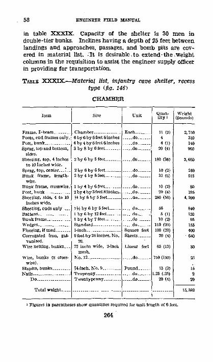
58 ENGINEER FIELD MANUAL
in table XXXIX. Capacity of the shelter is 30 men indouble-tier bunks. Inclines having a depth of 25 feet betweenlandings and approaches, passages, and bomb pits are cov-ered in material list. It is desirable~to extend the weightcolumns in the requisition to assist the engineer supply officerin providing for transportation.
TABLE XXXIX.--Material list, infantry cave shelter, recesstype (fig. 146)
CHAMBER
Item
Frame. I-beam......Posts, end frames onlyiPost, bunk ........Sprag, top and bottom,
sides.Sheeting, top, 4 inches
to 10 inches wide.Sprag, top, cente r. 'Bunk frame, length-
wise.Bunk frame, crosswise.Post, bunak ........Sheeting, side, 4 to 10
inches wide.sheeting, ends onlyBattens ..........Bunk frame .....Wedges.......Flooring, ilf sed.....Corrugated iron, gal-
vanized.Wire netting, bunks.
Wire, bunks (8 cross-wise).
Staples, bunks...-Nails -....---.-...-..-
Do ......1 - -..0 .
Size
Chamber.6 by 6 by 6 feet6inches4 by 4 by 6 feet 6inches3 by 8 by 6 feet ....
2 by6 by5feet ......... do.....
2by 6 by6 feet...2 by 4 by 6 feet......
Iby 4 by6feet ...2 by 4 by 3 feet 8inches.½ by 6 by feet....-----
1' by 6 by 6 feet.....1 by 6 byl2ftt --I by 4 by 7 feet..Standard -. --1-inch.9 feet by 24 inohes, No.
20.72 inchs wide, 2-inch
mesh.No. 12..........
-Sinch, No. 9..Tenpenny.........Twentypenny........
Total weight.....................
Unit
Eaceh....... do....__do.....__- .do -------
Quan.tity I
11 (2)44 (1)
20 (4)
ISO (36)
10 (2)32 (6)
10 (2)20 (4)
280 (56)
565 (1)
10 (2)110 (20)100 (20)
20 (4)
65 (13)
750 (150)
15 (3)1.25 (.25)
2 (4)
Weight(pounds)
2, 7503101409G0
3.600
240515
8so195
4.200
840120
95155400Ib640
30
25
220
15, 32
do....
_ do....--...do....
... do...... do....
..do......
Square feetSheets..
Linear feet
.- do -
Pound...- _ do.....
do.
I Figures in parentheses show quantities required for unit length of 6 feet.
264

FIELD FORTIFICATIONS
PASSAGES AND BOMB PITS
Gallery ces --........ Common- Eac..... 28 6,160Battens ..-...... y Iby 6by 10 feet. do 8 160Wedges- .... Standard ... o 112 160Sheeting, top, bomb 2 hy 6 by 6 eet do 14 280
pit.Sheeting, side, bomb 1f by 6 by 5 feet ---- do 48 72
pit.Furring strips, bomb 2 by 2 by 6 feet do... 12 9
lit.Nails .....- ..... Tenpenny... Pound... 8 S
Total weigbt .-........ - 7, 583
TWO INCLINES (25 FEET BETWEEN LANDINGS)
Cases, gallery ..--..... .Common- -.......... Eaheb. 62 13,640Battens ---------- 1 by 6 by 10 lfeet..... do 28 560Wedges- Stndrd....... do 248 345Fleaders and risers. 1__ bY 10 by 3 feet 6 .....do ...... 122 2,135
inches.Nails -- ....-....-... - Tenpeony.......... Pound....- 10 10
Total weigbt--. ------ -------- 16, 690
TWO APPROACHES
Cases, gallery ..-- . Comm on ..... Each..... 2 440Diagonal braces, tocut 2 by 6 by 8 feel --....... do. 2 65Baffle boards ........-- 2 by 12 by 3 feet 6 --- do 2 5f
inches.Reretting boards....: 1 by 6 by 10 feet .. do ...... 8Stair stringers ....... _. 2 by 10 by 10 feet -- do....... 2 130Stair treads .....- ,- 2 by 10 by 6 feet ...... do.... 4 160Stair risers....--..... 1 by 10 by 3 feet do 6...... 60Wedges - -.......... Standard ............ do .... 1Concrete brtrsters ..... -- do --- do.. 84 12,180Sandbag -- -........ do .....---- --- do 60 30Nails........-- Twentypenny ....... Pound 10 10Wire, bursters .....-- No. 12- --...........------- Linear feet 4
Total weight .................... ---------- 13,304
265
58

58 ENGINEER FIELD MANUAL
MATERIAL LIST CONSOLIDATED
Item
Gallery frames, I-beams, ch her size --Gallery cases, common size6 by 6 by 6 feet 6 inches ..............4 by 4 by 6 feet 6 inches ----..........----3 by 8 by 6 feet.........2 by y tfeet 6 inches......2 by 10 by 10 feet - --2 by 10 by 6 feet...................2 by 6 by 8 feet ......2 by 6 by 6 feet-----------..2 by 6 by 5 feet (or equivalent 4 to 10 inches
wide).2 by 4 by 6 feet.2 by 4 by 3 feet 8 inches............2by 2by 6 feet.. .............1½ by lO by 3 feet 6 inches....1 by 6 by 5 feet (or equivalent 4 to 10 inches
wide).I by 10 by 3 feet ...I by 6 by 12 feet ........ ----- -........1 by 6 by 10 feet.....I by 4 by 7 feet...................1 by4by6 eet ....----------..............--Wedges, standard .................1-inch flOring ....... ..Corrugated iron, galvanized, 9 feet by 24
inches, No. 20.Wire netting, bunks, 72 inches wide, 2.inch
mesh.Wire, bunks, No. 12 ................Wire, binding, No. 12 ...Staples, N-inch, No. 9--------------....................--Nails, tenpenny....................Nails, twentypenny .................Concrete bursters, standard ......Sandbags, standard ......-....-........
Total weight ........
Unit
Eachl ...._ do......... do ...........
do... do..do .....--.--do....
do....do ....
. do......
. do......... do........__ do.........do...do....
.... dodo
.... do ._ do.....- do.....
Square feet.....Shots ....
Linearfeet....
..... do....---.... do......Pound ........... do.....
do...Each .:
..do...
I Figures in parentheses show quantities required for unit length of 6 leet.
266
Quan-tity I
11 (2)
20 (4)2
2
2
10 (2)194 (36)
32 (6)20 (4)12
122a84 (56)
65 (1)
Weight(poonds)
2, 75020,240
310140960
51130160
65240
3, 880
51519595
2, 1355, 760
6120120
441010
478100
20
(2)(2)
(20)(20)(4)
65 (l3)
ga95
67dso
640
30
254
152030
12, 1803U
(150)
(3)(.25)
(4)
750
2Ognis20
3084
I 60 I
.. I ---- -1 52, 909
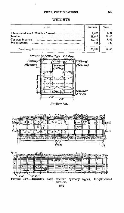
FIELD FORTIFICATIONS 58
WEIGHTS
Item Pounds Tons
I-beams and shoes (hebamber frames) ............... 1,025 0.51Lumber ...-................... 38,910 19. 45Conerete bursters....- ...... --.. ........-......- ------ 12, IO 6.09Miscel]aneous - ............ 9........ 7 4
.40
Total woeight -...-- 2, 909 26. 45
"Sr t'4
.rshettiny7 C09 3p7
sninflo t:i" ' lsader
section .
267
267

ENGINEER FIELD MANUAL
(3) An example of a gallery type infantry cave shelter withmaterial list in table XL is shown in figure 147. Materialsfor inclines, approaches, passages, and bomb pits are notincluded. Capacity of the shelter is 24 men in double-tier.bunks. Estimates for any arrangement of connecting pas-sages and entrances may be made by using propercombinations.
TABLE XL.-Material list, infantry cave shelter, gallery type(fig. 147)
for. m ~Si unit Qan- ihtIt i Ur I (pounds)
Frames, gallery --....- Great .. Each 13 (2) 4,875Post, bunk ......... 4by4byeet6inches -- do 14 (2) 485Sprag,top and bottom, 3 by 8 by 6 feet- do....... 24 (4) 1,150
sides.Sheeting, top, 4 to 10 2 by 6 by 5 feet ..... do ....... (30) 3,600
inches wide.Bunkframe,crosswise, 2 by 4 by 8 eet-------- do 7 (1) 150
to cut.Bunk frape, length-
wise.Sprag, top center....
Do.----Sheeting, side, 4 to 10
inches wide.Sheeting, ends only, 4
to 10 inches wide.Wedges -......------Flooring...........Corrugated iron, gal-
a nized.Wire netting...
Wire, bunk ...Staples ......Nails...........
Total weight. ---
2 by 4 by 7 feet.
2 by 4 by 6 feet -.. do...
1% by by 5 feet
Standard......1-inch.8 feet by 24 inches,
No. 20.36 inches wide, 2-inch
mesh.No. 12...--*W-inch, No. 9......Fortypenny.......
... do
.... do ....
do
.- do.Squore feet..Sheet.
Linear feet.
.. do---Pound.
..do -
43 (8) 895
48 (8) 89512 (2) 190
360(60) 5,400
30 450
130(20) 18090(15) 36024 (4) 69G
156(26)) 40
480(80) 1212 (2) 1212 (2) 12
19,402
268
I Figures in parentheses show quantities required for unit length of 6 feet.
58

FIELD FORTIFICATIONS
WEIGHTS
Item Pounds Tons
Luber -........................... - -8,- - - 3 9.31isellneous ..----- ------.................... ------------- 772 .39
Total .................- ......... 19,402 9. 70
C. Command posts.-(1) Several plans of command postsare shown in figure 148. The lay-out of command posts can-not be standardized as each situation will present a differentproblem in providing floor space required with least expendi-ture of labor and material. Floor space required for com-mand posts of various Units is given in paragraph 64. Forother types of command posts see paragraphs 39e and 57e.Material lists for complete work may be computed as here-tofore indicated.
(2) Note that in the suggested designs of command postsin figure 148 all passages are of the common gallery size andthe rooms are of the chamber gallery size and similar tofigure 146. In general, command posts for the larger unitswill consist of a combination of rather small chambers atright angles to the passage and long recessed chambers alongthe passage. The small chambers will normally be used forcombined offices and quarters for commissioned personnel ofthe staff while the long recessed chambers will contain bunksfor the enlisted men. Chambers built at right angles to thepassages should not extend more than 15 feet unless ventila-tion holes or shafts are constructed in the end of the room.
(3) In computing floor space of shelters to be used forcommand posts, the area of passages should not be includedsince all passages must be kept open and unobstructed.
g. Artillery.-(1) Lay-outs for artillery cave shelters areshown in figures 149 and 150. Note that the standard cham-ber gallery and the common gallery sizes are used. Estimatesfor material for arrangements shown or for any adoptedarrangement may be made as heretofore indicated.
(2) The arrangement of the four guns of a battery in lineis not essential as they may be echeloned or divided into
262375°-40--18
58
269

58 ENGINEER FIELD MANUAL
groups. Not more than 15 men per piece should be housed atthe gun, the remainder of the unit being housed in a shelter200 or 300 yards away. It is advisable in some cases toconstruct the command post away from the guns. A first-aidshelter should be located 200 or 300 yards away.
* II h e =7'bt-- ------4 1 r 51"'C-----------
L .. L ...... .l L s.a.... ...
sJiM*r Jsucnnanry dplato
C. P. for a small unit such as an infantry platoon.
C. P. for a company
C. P. for a battalion
C. P. for a regiment
FmGRE 148.-Lay-out of command posts
270

FIELD FORTIFICATIONS 55
n7 1111 t
271
a
to
0~
A
0.0
C,
.ea1

58 ENGINEER FIELD MANUAL
C
it
IA
4
272
0
Tog0
1"
I
0H
5I
,C
Ep
IY
I
w
R

FIELD FORTIFICATIONS 58
a:al
-,g
urc , ,i a l4 I C
n C jf : : _ I3F5 =
is~ i___
273

ENGINEER FIELD MANUAL
(3) Where conditions prohibit construction of cave shelter,some form of cut-and-cover shelter may be substituted. Thedesigns shown in the figures are not intended for any partic-ular gun or howitzer.
h. First-aid-(1) Figure 151 shows a shelter adapted forfirst-aid use, having ease of passage for litter bearers throughpassages, aisles, and inclines. Note that rooms are madewith standard chamber gallery frames and connecting aisleswith great gallery frames with the caps and sills shortenedto a length of 5 feet 6 inches. Estimate for material forthis arrangement may be obtained as heretofore indicated.
(2) The 45 ° incline is too steep for handling litters withease; an incline of about 31' is preferable.
i. Protection of entrances.-(l) Entrances should be con-cealed from enemy observation and protected from destruc-tive shell fire. Usually they open to the rear (out of thefront slope of a trench), occasionally to a flank, but neverto the front. They should be so far apart that more thanone cannot be blocked by a single shell burst, usually 50 feetand never less than 40 feet, There should be at least oneangle or bend in the trench between them, and they shouldbe at least 5 feet from such angle.
(2) There should be at least 3 feet initial headcover overthe top of the first frame of the entrance proper, and aburster course from 5 to 12 inches thick composed of rock,broken stone, or concrete slabs should be placed above theentrance not more than 1 foot from the surface. No attemptshould be made to strengthen the head of the incline by logs,rails, I-beams, concrete arches, extra heavy timbers, or com-plicated bracing. Amount of protection gained in this waywould be much more apt to cause a serious block in the en-trance if hit because of difficulty of clearing away brokenlogs, twisted rails, etc.
(3) No form of defense against grenades which would tendto obstruct the entrance to a cave shelter or delay rapid exitcan be permitted. The only protection allowable is a grenadeor bomb pit at the bottom of the dugout constructed by lininga shaft in prolongation of the inclined shaft to a depth of 6feet below the gallery level (see fig. 146). This is constructedafter the shelter is completed and may be used also as a
214
58

FIELD FORTIFICATIONS
sump, but must be kept clear of debris, Grenade pits areconstructed only in shelters in forward areas where raids arelikely to occur.
(4) The best protection for entrances to cave shelters isconcealment from ground observation and from discoveryby aerial photography (see FM 5-20). To avoid groundobservation, entrances should be located on reverse slopes,in old quarries, sunken roads, etc. To avoid detection byaerial photography they should be located in trenches usedfor other purposes. They should cause no visible break inparapet nor otherwise modify appearance of the trench.Rectangular notches in or projections from firing crests oftrenches are especially conspicuous and easily distinguishedon aerial photographs. Locating shelters in woods protectsthem from both ground and air observation.
i. Quantities of materials required.-(1) Material lists forany lay-out in which the standard materials are used maybe made up from the list for each type of structure includedin. the lay-out. Thus, for a cave shelter, the tables for acertain type of chamber, an entrance passage (inclined orotherwise), and an approach to entrance will ordinarily beused (see fig. 146). If several chambers are connected under-ground, the table for the proper size of gallery for the con-necting passage will also be used.
(2) The following allowances have been made in tables formaterials:
(a) Standard wedges per set:Framed gallery_ -.. ___ ..................._ 10Cased gallery_ ---- __._______-___--_________ 4
(b) Sandbags, per square foot of revetting face_______ 3(c) Bursters, per entrance (7- by 6-inch)_ … - _______ 42(d) Miscellaneous:
Wire netting, 36-inch, 2-inch mesh, per bunk,linear feet _--_________._.__.___.___-- -___ 6.5
Staples, per bunk, pound, 7/s-inch, No. 9 -____ .5k. Rate of work.-In calculating size of working parties and
rate of work, the following figures may be taken as average.
275
58

58-59 ENflNEER IEULD MnAUAL
These parties perform all work including timbering, exclusiveof disposal of spoil on the surface.
(1) Inclines.--Common gallery, size 6 feet 4 inches by 3feet inside clear dimensions.
1 man picking and timbering.1 man filling sandbags and timbering.
1 relef_ 1 man carrying for each 10 feet that workingface is from entrance.
Average progress for each shift of 8 hours about 3 feet 6inches; may vary from 1 to 7 feet, depending on all conditions.
(2) Passages.-Galleries, common gallery size.Working party same as for inclines.
Average progress for each shift of 8 hours about 4 feet.May vary from 1 to 8 feet, depending on all conditions.
(3) Chambers.-(a) Chamber gallery size, 6 feet 4 inchesby 8 feet inside clear dimensions.
2 men picking.4 men filling sandbags and timbering who relieve
pickmen as they tire.Add I man per pickman for each 10 feet of carry.
Average progress for each shift of 8 hours about 3 feet.May vary from 1 to 6 feet, depending on all conditions.
(b) Great gallery size, 6 feet 4 inches by 6 feet 6 inchesinside clear dimensions.
Working party same as (a) above.Average progress for each shift of 8 hours about 3 feet
6 inches. May vary from I to 8 feet, depending on all con-ditions.
(4) Surface carrying party:1 man can carry 100 sandbags a distance of 200 feet
in 8 hours on surface under ordinary trench con-ditions.
1 bag equals 0.5 cubic foot, about 50 pounds.(5) Labor underground can be economized by use of min-
ing cars, windlasses, etc.* 59. DrAINrAGEa. Surface and rain water.--Surface andrain water must be excluded from all shelter entrances. Ifdrainage of the trench is sluggish, two sumps must be dug
276
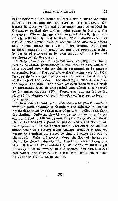
FIELD FORTIFICATIONS
in the bottom of the trench at least 6 feet clear of the sidesof the entrance, and strongly revetted. The bottom of thetrench in front of the entrance must then be graded tothe sumps so that the highest point comes in front of theentrance. Where the entrance takes off directly from thetrench baffle boards must be used. These should extend atleast 6 inches beyond sides of the entrance, and to a heightof 10 inches above the bottom of the trench. Admissionof direct rainfall into entrances must be prevented eitherby design of entrance or by construction of some form ofweatherproof shelter over it.
b. Seepage.-Protection against water seeping into cham-bers is essential, particularly in the case of cave shelters.In a cut-and-cover shelter this is accomplished by placingcorrugated iron in the roof above the sheeting (see fig. 130).In cave shelters a strip of corrugated iron is placed on topof the cap of the frame. The sheeting is then driven overthe top of the iron. The space between caps is filled withan additional piece of corrugated iron which is supportedby the sprags (see fig. 147). Seepage is thus carried to thesides of the chamber where it is collected in a gutter leadingto a sump.
c. Removal of water from chambers and galeries.-Suchwater as gains entrance to chambers and galleries in spite ofprecautions must be taken care of or it will collect and floodthe shelter. Galleries should always be driven on a i-per-cent, or 1 foot to 100 feet, grade longitudinally and all slopesshould fall toward a point or points where the water canbe disposed of. If the shelter has a level entrance such asmight occur in a reverse slope location, nothing is requiredexcept to regulate the slopes so that all water will run tothe mouth. Using a 1-percent slope, the floor of the galleryshould be sloped laterally and a gutter formed along oneside. If the shelter is entered by an incline or shaft, a pitor sump must be formed at the bottom into which watercan collect, and from which it can be raised to the surfaceby pumping, siphoning, or bailing.
277
59
60-61 ENGINEER FIELD MITNUAL
U 60. VrNqrLATIoN.-Ventilation, particularly in reference tocave shelters, is very important and should be given carefulconsideration. It includes the following problems:
a. Providing a sufficient circulation of fresh air throughthe incline, shafts, galleries, and chamber.
b. Gasproofing, or exclusion of gas from all parts of theshelter.
c. Providing a supply of pure air by means of air purifierswhen entrances and ventilation shafts are closed during aprolonged gas attack.
* 61. CIRCULATION OF FRESH AIR.-a. In the case of surfaceand cut-and-cover shelters no serious difficulties arise, andthe problem may be handled usually by keeping entrancesopen.
b. In the case of cave shelters ventilating shafts in addi-tion to entrances are usually necessary. They are in theform of small vertical shafts which may be bored from withinafter completion of the shelter. A stovepipe through oneof these shafts assists circulation of air materially. In somecases where the ventilating shaft is not provided, a smallfire near one of the entrances will create a draft and thuskeep the air purified. In very large and elaborate systemsof shelters a forced draft may be caused by means of fans.
c. A gallery should not be driven more than 60 feet withoutartificial ventilation. The only possible way of ventilatinga gallery with a single opening is to force fresh air to theworking breast which may be done through a duct of woodor metal, or canvas or other hose. A pressure blower workedby hand or power is among the essential items of miningequipment. For excavations of moderate extent a portableforge forms a convenient ventilating device. If a gallerypasses under surface cover, drill holes made through the roofand breaking the surface under protection of the cover maybe used to promote ventilation. In a system of gallerieshaving two or more outlets, air may be exhausted from oneand drawn in through the other. Screens or doors may bearranged to compel desired distribution of fresh air. Vacuumoperation is.never as satisfactory as a pressure system.
278

FIELD FORTIFICATIONS
* 62. GASPROOFING.-a. Due to their low level protected shel-ters are particularly subject to gas concentration, and in allcases protection must be provided by means of curtains inentrances. During extended gas attacks men must be enabledto work and rest inside the shelter with their gas masks off.This is most important in shelters where men are placedpending evacuation who are so wounded that they cannotwear a gas mask, in shelters used for medical dressing stations,telephone central and signal stations, observation posts, head-quarters, and other activities whose efficiency would be con-siderably reduced by wearing the gas mask.
b. Adjustable curtains made from wool or cotton blanketsand supported on a light, sloping framework are the mosteffective means of excluding gas from shelters. The curtainand framework must be assembled at the shelter site andbuilt to fit each shelter.
c. Gas curtains must be-(1) Impervious to gas.(2) Of the simplest possible construction.(3) Such as to permit rapid exit in case of a raid.(4) Readily rolled up and put out of the way when not
in use.(5) So arranged as to drop in place instantly.Ordinary blankets soaked with water or oil may be used.
A more efficient curtain than this is needed and experimentsto date indicate that a wool or cotton blanket faced with animpermeable fabric or impregnated with a suitable chemicalagent will be provided.
d. Curtain frames should be nailed securely to the sidesand top of the entrance timbers, close-timbered for thispurpose. It is sometimes necessary to place curtain frameson the steps, but they should be placed in horizontal entrancesor horizontal approaches to inclines whenever possible. Thecurtain frame for stairways (fig. 152) is similar to that usedfor horizontal entrances.
279
62

ENGINEER FIELD MAN-IAL
In ]r
Sit] td
* Ics~tad~ I. ia Leoose end fasie¢ed
l ^ronl at1¢ 'I¢. .- .
.lstkot hu.ld ctear r t , a lasa 1 LFronl £tev Setion fers El.e
Wi Gast is e
TI NMorizonal E rasre
peces shown thusm
FIGURE 152.-Gas curtain details.
280
62
,)�' ---

FIELD FORTIFICATIONS
TABLE XLI.--MateriaI list, gas curtain for protected shelters(fig. 152)
Iteom
Curtain:Blanket.......... 6by7Tacks....Nails.. TcnpSmall weights......Laths ........ by
Do-....... i bBottom strip. - by ITop cleat I by
Frame:Frame pieces, front 2 bySash -........... by'Molding ....... I by:Top and shelf ...... I by'Furring ...- 1 byNail -..... .... Tena
Do .........- Twet
Size
7 feet.................
enny .....
I by2fee t 8 inches..1 by 2 feet 2 inches ...--
2 by 2 feet 8 inches ...2 by 2 feet 11 inches -... .I-..do ......
I by 16 feet -..4 by 16 feet..l........2 by 1 feet.........S by 8 feet.........2 by 12 feet..........enny .................Itypenny ..-- ----.. . -.--
e. Front, rear, and side views of the curtain are shownin figure 152. The curtain is fastened to the frame at thetop by a cleat. Three inches of blanket material are leftprojecting above the top of this cleat to be later fastenedtightly to the underside of the cap. The 1-inch by 2-inchstrip at the bottom of the blanket must be of perfectly straightmaterial, and when it becomes warped it should be replacedimmediately. When used in an incline this cleat is allowedto rest on the floor of the steps and the curtain should clearthe side lagging by Y2 inch. Judgment should be used incutting the blanket to the proper size in an opening. Weightsmade from nuts, washers, scraps of iron, bullets, etc., arefastened along the side edges of the curtain. Gas curtainsshould clear the side lagging'by /2 inch and the floor by 1/2inches when placed in horizontal entrance approach. Whennot in use the blanket is rolled up and placed on the shelfat the top of the frame.
f. Number and position of curtains.-There should be twogas curtains in every entrance in order to make a gas trapor space between the two and permit entry and exit during
281
Unit
Each.....Package....Pound .....Each ..
do........ do
..... do....
Quantity
122
1622
222
.... do......___do...-.
_ _do .....___do ....
Pound........do...
62
I

ENGINEER FIELD MANUAL
attack without allowing an appreciable amount of the gasto get into the dugout. The curtain frame should be seton a slope of 3 on 1. Whenever possible curtain frames shouldslope in opposite directions with curtain on the outside (seefig. 152). The space between the two blankets should beas great as possible in order to secure maximum dilution ofthe gas which will inevitably get in. In first-aid stationscurtains are placed at least 8 feet apart or at top and bottomof the incline. In short horizontal entrances the curtainsare necessarily closer to oneanotheri but the space shouldbe as great as possible and never less than 4 feet at the top.
g. Other openings.-Curtains may be made for windows inthe same manner as for entrances, except that only one cur-tain need be installed. Holes made for periscopes and forventilation purposes should have blanket-covered plugs hang-ing nearby to stop up the openings in case of a gas attack.Old clothes may also be used. Any openings behind entrancetimbers should be filled with clay, old clothes, or sandbags.All crevices around the curtain frame in either the frame orentrance timbers should be calked with pieces of blanket.Unless this is done the curtains are useless. If a dugout isnot practically gastight, all pretense of protection should beremoved.
h. flooring or steps in front of a gas curtain should be keptclear of all mud or refuse. The seal between curtains andframes is more effective if the curtains and frames are keptmoist at all times. They should be sprayed daily with wateror with gasproofing solutions which should always be kepton hand. A pail or other container filled with fresh chlorideof lime should be kept on hand at all times in gasproof dug-outs. During gas attacks or when men have been exposedto gassed terrain, the chloride of lime container should beopened and placed in the gas trap between the curtains foruse of all personnel entering the dugout to destroy mustardgas on the feet or hands. Mustard gas or similar agent car-ried into a dugout soon converts the dugout into a gas trap.
l 63. AIR SrPPLY DnRING GAS ATTACK.-a. In any future useof chemical agents in war, such agents will in all probabilitybe used to maintain a continuous concentration in certainareas for comparatively long periods of time. Assuming that
282
62-63
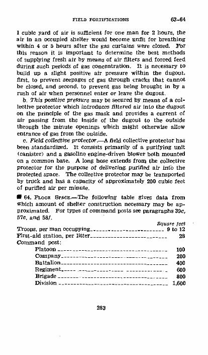
FIELD FORTIFICATIONS
1 cubic yard of air is sufficient for one man for 2 hours, theair in an occupied shelter would become unfit for breathingwithin 4 or 5 hours after the gas curtains were closed. Forthis reason it is important to determine the best methodsof supplying fresh air by means of air filters and forced feedduring such periods of gas concentration. It is necessary tobuild up a slight positive air pressure within the dugout,first, to prevent seepages of gas through cracks that cannotbe closed, and second, to prevent gas being brought in by arush of air when personnel enter or leave the dugout.
b. This positive pressure may be secured by means of a col-lective protector which introduces filtered air into the dugouton the principle of the gas mask and provides a current ofair passing from the inside of the dugout to the outsidethrough the minute openings which might otherwise allowentrance of gas from the outside.
c. Field colledtive protector.-A field collective protector hasbeen standardized. It consists primarily of a purifying unit(canister) and a gasoline engine-driven blower both mountedon a common base. A long hose extends from the collectiveprotector for the purpose of delivering purified air into theprotected space. The collective protector may be transportedby truck and has a capacity of approximately 200 cubic feetof purified air per minute.
* 64. FLOOR SPAcE-The following table gives data fromwhich amount of shelter construction necessary may be ap-proximated. For types of command posts see paragraphs 39c,57e, and 58f.
Square feetTroops, per man occupying ------------------------- 9 to 12First-aid station, per litter _________________________ 28Command post:
Platoon …_…-- - -- --__ �_…_ … - -- -- -- -- -- -- -- --__ 100Company_ __-_.___________._.__________._ 200Battalion_ ------ ______.__________________ __ 400Regiment- o.._o--__o____-____ -___---________ 600Brigade --__ --- ---__-___B__-__o______________ 800Division -__ --- - ---___-___-___-_______________ 1,600
283
63-64

ENGINEER FIELD MANUAL
* 65. TIME FOR CONSTRUCTION.--a. Table XLII gives estimatesfor construction time for various shelters as illustrated inthis section. Estimates are based on assumption of averagefirm soil, well-trained men, and material delivered at site.They include time of the labor required to dispose of exca-vated material and to handle construction material. Thearea used is that of the room providing shelter and does notinclude areas in passageways or inclines. Estimates are sub-ject to considerable uncertainty on account of the variety ofconditions encountered.
b. With men untrained in this character of work the man-hours per square foot of chamber may be increased 50 per-cent; after a period of experience, however, a detail shouldapproach the. estimate. Time of construction may beshortened by increasing size of the detail where conditionsof work make this possible.
284
65
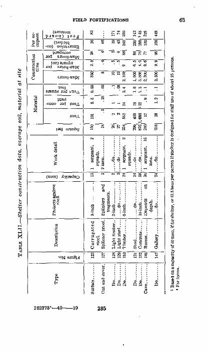
FIELD FORTIFICATIONS 65
O_ 'amse;'z /I c ro C 2
X o ,no) -onv-a|
o .d smoq-utW 5|
§ig
1.ra wnbs .~dSoL ~ ' ~i 4,
t~~~~~~~~~~~~
E ._ 100;"~Pk, e
_~o SDlioo;y 4 E ~ P "0
~'I =" :,
i~i:
.......nbg d .. _
o X Ward < e: =i if o
$ O nnoo. -d SwL o
u~ ~~·· _ %} mbs|_ wgsi|b
Ia . :o e.
' r w~~'I = e O v S " '
Z o =_ C _ W ~~~o i ;
~~~~~~~
z ~ ~~~ m° ° -1 = :zz E 8u >
"~~~~~~~~~~~~
H ~~~-N n sl _ 3__.,,,,,!. .,, , .
26235°40e--19 25
2C2375° { 1-- 9 255
66-67 ENGINEER FIELD MANUAL
SECTION IX
SUMMARY
I 66. GENERAL.-a. Field fortifications, hasty or deliberate,are generally laid out and constructed by the occupyingtroops.
b. Engineers assist field fortification work by-(1) Supply of tools and materials.(2) Execution of works of general use.(3) Lay-out and construction of rear positions.c. Field fortification works consist of fox holes, trenches, ob-
stacles against both foot and mechanized troops, weaponemplacements, protected shelters, clear fields of fire, andcamouflage.
d. Open works protect against light artillery and fragmen-tation bombs, covered works generally against medium shellsor bombs.
e. Allow for effects of surface and ground water and typeof soil to be encountered in siting and constructing field works.
f. Use existing terrain features to reduce fortification work.
* 67. TERRAIN APPRECIATION.-a. Evaluate terrain in terms ofobservation, fields of fire, cover and concealment, obstacles,and communications; of these, observation is usually the moreimportant.
b. A terrain compartment is an area bordered on at leasttwo sides (opposite sides) by terrain features which preventground observation into the area. It may form either a cor-ridor or a cross compartment.
c. Boundaries in attack should coincide with boundaries ofcorridors.
d. Boundaries in defense should fall between corridorboundaries so as to assign avenues of approach to units mostaffected thereby.
e. A cross compartment favors the defense,f. To assist terrain studies on map or photograph, one or all
of the following devices may be used: emphasize drainagelines, add ridge lines, emphasize certain contours, see TM5-220.
g. On tactical studies of terrain see FM 101-5 for details.
286

FIELD FORTIFICATIONS
* 68. ORANrZATION OF THE GROUND.-a. To develop fullstrength of a defensive position-
(1) Dispose troops so their fires are coordinated.(2) Provide fields of fire.(3) Construct field fortifications.b. Use hasty fortifications when under fire or threat of fire,
deliberate when out of contact with the enemy.c. Develop hasty fortifications into deliberate types as time
permits.d. A battle position consists of a system of mutually support-
ing defensive areas organized in depth, as follows:(1) Platoon defense area.-Smallest defensive area, garri-
son usually a platoon.(2) Company defense area.-Two or more platoon defense
areas under a company commander.(3) Battalion defense area.-Two or more company defense
areas under a battalion commander. It is the basic unit ofdefense, and can defend on average terrain a front of 800 to1,500 yards, depending on terrain and tactical situation.
(4) Regimental sector.-Front defended by a regiment,completely covering battle position in depth.
e. A battle position contains three echelons of defensiveareas, the main line of resistance (MLR), the battalion re-serve area, and the regimental reserve line (RRL). Mini-mum distance between the MLR and RRL is 700 yards,maximum, 1,800 yards.
f. A battle position should when practicable be protectedby an organized outpost area well to the front; it may bereinforced by one or more reserve battle positions connectedby switch positions.
* 69. EFFECTS OF PROJECTILES.-a. For protection against cal-iber .30 to .50 bullets, special steel or (tank) armor about fourtimes their caliber in thickness is required; they penetratesteel twice their caliber in thickness.
b. The greatest destructive effect is produced by the largerprojectiles with long delay fuses striking at angles of impactover 400 giving maximum penetration such as those droppedfrom aircraft and fired from 155-mm or larger howitzers.
* 70. TRENCHES.-a. For protection, troops may have to workat night.
287
68-70

0 ENGlINEER FIELD MANUAL
b. No night work should be performed that can safely bedone by day.
c, Hasty trenches.-(1) Skirmisher trench, protection fromsmall-arms fire only.
(2) Fox hole (when completed to standing type), pro-tection against small-arms and light artillery fire.
(3) Shell holes, quick protection with little labor.(4) Slit trenches, protection for machine-gun and artillery
personnel.d. Clearing fields of fire.-(l) Leave a thin natural screen
to hide defender's position,(2) Clear thick brushwood and undergrowth and leave
overhead cover.(3) Leave large scattered trees standing, cutting off only
the lower branches.(4) Demolish walls only when resulting debris will not
give more protection than the wall itself.(5) Buildings, knock down low ones, leave large ones
standing and burn them.e. (1) Tracing of deliberate trenches should be supervised
by an officer.(2) The octagonal trace is the best fire trench and the
wavy trace is the best communication trench. The zigzagtrace is the simplest, easiest to construct and maintain, andcan be used as a fire or communication trench or as theechelon trace in gaining ground toward or away from theenemy.
!. Standard profiles.-The simple standing trench is firstprofile sought when constructing trenches rapidly. Developit to type A which is standard for hard ground. Developtype A to type B in soft ground. Type C wide communicationtrench is used in special cases for main thoroughfares.
g. Planning and reconnaissance.-Must be careful andthorough. Data required: trench locations, profile to be used,amounts of time, labor, tools, and materials required, andcovering force, if any.
h. Trench drainage.--() Prepare drainage plans and com-plete essential drainage work before starting other work.
(2) Exclude surface water from trenches.
288

FIELD FORTIFICATIONS
(3) Dispose of water by drainage ditches, sumps, pumping,or bailing.
(4) Provide trench bottom with minimum slope of I per-cent with no low spots.
(5) Site trenches to drain toward natural drainage lines.i. Revetments may be-(1) Retaining wall type, usually of sandbags, for fills,
parapets, and breastworks.(2) Surface type, consisting of revetting material such as
wire netting, brush, etc., and its supports, and used mainlyin retaining the slopes of trenches. A-frames are standardsupports.
j. Breastworlcs are built above ground where water, rock,or very hard material makes trench excavation impracticable.
k. Trench accessories.--() Observation posts should give-(a) Maximum clear field of view.(b) Immunity from enemy fire which is best obtained by
concealment.(2) Latrines.-Provide for-(a) At least 4 percent of the command.(b) If occupied for any considerable time, for 8 percent of
the command.(3) Sign posting.--Checked or provided in new areas.
[ 71. OnsTncLEs.-a. General.-(1) Take maximum advan-tage of natural obstacles.
(2) Barbed wire most effective artificial obstacle againstfoot troops.
(3) Double-apron fence most effective pound for pound andis standard tactical obstacle.
(4) Typical protective obstacle, four-strand fence com-pletely surrounding locality.
b. Location and construction of artificial obstacles.--(1)Cover by defensive fires.
(2) Keep protective obstacles always under observationwithin 100 yards.
(3) Conceal obstacles by natural features.(4) Provide all around protection not closer than 30 yards.(5) Use belts 4 to 10 yards with intervals of 15 to 40 yards.
289
70-71

71-72 ENGINEER FIELD MANUAL
c. Entanglement material requirements for a defensiveposition.-(l) Weight of tactical wire (double-apron fence)equals weight of protective wire (four-strand fence).
(2) Linear yards of tactical obstacle equals 1/4 timesfrontage.
(3) Linear yard of protective obstacle equals 31/a timesfrontage.
(4) Tactical wire weighs 10 pounds and protective wireweighs 4 pounds per linear yard of obstacle.
(5) Battalion area with frontage of 1,500 yards requiresabout 20 tons of pickets, wire, etc., for double-apron tacticaland four-strand fence protective entanglements.
d. Dead abatis.--() Interlace branches, cut trees partiallythrough 2 to 3 feet above ground.
(2) Addition of barbed wire increases effectiveness of theobstacle.
e. Inundations.-Barbed wire and artificial obstacles in-crease their effectiveness.
f. Underwater beach obstacles.--() Require utmost in-genuity; must be adapted to local conditions.
(2) Barbed wire when used must be more plentiful andmore securely anchored than for land obstacles.
* 72. EMPLACEMENTS.-a. For infantry weapons.--() Auto-matic rifle emplacements are used in trenches or fox holes.
(2) Machine guns are habitually used in emplacements.(3) In hasty emplacements concealment is of paramount
importance and as much protection as possible (may benearby slit trenches) is provided.
(4) In deliberate emplacements more physical protectionfor personnel is provided either at the gun position or nearby.Concealment is still of considerable importance.
b. For field artillery.--() Light artillery seldom dig inexcept for deliberate positions.
(2) Banks, particularly along roads, especially adapted toconstruction of artillery emplacements in them.
(3) Trenches for cannoneers and parapets follow afterconstruction of the gun emplacement.
c. For antiaircraft.-(1) Concealment and camouflage aremost important.
290

FIELD FORTIFICATIONS 72-73
(2) Sunken emplacements or parapets constructed whenpossible.
(3) Parapets provide splinterproof protection as a min-imum.
73. PROTECTED SHELTERS.-a. Choice of type depends on-(1) Use to be made of shelter.(2) Degree of protection necessary.(3) Terrain.(4) Location.(5) Cover and concealment.(6) Observation.(7) Time, material, and labor available.(8) Ground and subsurface conditions.b. Application of types.-(1) Splinterproof or light shelters
used in advanced positions in early stages of organizationof the ground in mobile situations.
(2) These may be developed into light shellproof sheltersas time permits or light shellproof shelters may be builtinitially for rear positions.
(3) Heavy shellproof and cave shelters used only instabilized situations.
c. Overhead cover must provide for-(1) Bursting layer.(2) Distributing layers.(3) Intermediate shock absorbing layers.d. High early strength cement materially reduces con-
struction time. Attains adequate strength in about 'A, ofthe time for standard cement.
e. Surface shelters may be-(1) Concealed in woods or behind reverse slopes; these
may vary from the hasty splinterproof type to light shell-proof type.
(2) Reinforced buildings in a village and should begenerally of at least the light shellproof type.
(3) Concrete providing at least light shellproof protection.(4) Small light shelters for protection of ammunition and
stores.f. Artillery ammunition shelters must be waterproof; con-
cealment and storage below ground level are desirable.
291

73-74 ENGINEER FIELD MANUAL
g. Cut-and-cover shelters.-Depth of excavation greaterthan about 12 feet impracticable. If greater depth neededuse mining methods (cave shelter).
h. Cave shelters.-(1) Two types are-(a) Recess.(b) Gallery.(2) Entrances must be concealed and protected.(3) Emergency exits must be provided.(4) Ventilation, drainage, and gasproofing are particularly
important.i. Drainage.-(1) Exclude surface water.(2) Exclude all seepage possible and collect balance in a
sump to be pumped out.(3) Give galleries a minimum 1 percent slope longitudi-
nally and laterally.j. Ventilation.-Obtained by ventilation shafts and power
or hand blowers.k. Gasproofing is obtained by--(1) Gas curtains to exclude
gas.(2) Collective protectors to supply pure air.
* 74. GENERAL RULES FOR EXECUTION OF FIELD WORKS-General rules applicable to all details of field fortificationsare-
a. Assign each organization to construction of the worksit will itself occupy and defend and for which it is bestequipped and trained. Assign work of general interest suchas clearing fields of fire, improvement of routes, etc., tospecial units and attached troops.
b. Avoid splitting of units or violation of tactical integrity,Use complete squads, platoons, and companies wheneverpossible. Assign a unit to groups of similar tasks all in thesame locality.
c. Without enough men to finish all tasks in the allottedtime, make sure that the most important tasks will be com-pleted on time, and others as far as possible in order ofimportance.
d. To observe all of the foregoing rules precisely will neverbe possible. Each should be given all the weight that thesituation permits.
292

INDEXParagraph Page
Abatis .--._.__...._. . . 43 149AccessoTies, trench . . .._.._.. _. . ... . . ___ 39 105Air:
Fresh, circulation in protected shelters -. _ 61 278Supply during gas attack ---------- ___.. 63 282
Aircraft projectiles, effect of_ ---------- _-. . . . 29 45Antiaircraft materiel emplacements …._._. ._ 50 201Areas:
Defense:Battalion, -_-_--____-_-.-. 20 31Company _-----__-- --- 19 30platoon ---------------------____-_. 18 29
Outpost -_---_-_----------.---------. 24 37Artillery-
Ammunition shelters, protected .------. ___ 56 225Emplacements …… . .... ... _49 186Projectiles, effect of . . . .................. 29 45Support ----------- --- 23 36
Barbed wire obstacles ....... ......_....... 42 118Battalion defense area ---------------..---- 20 31Battle position_ . .... .......... ._17 25
Reserve --.----------------------------__ 25 41Breastworks --------- --- 38 103
Cave shelters ..-...................... 58 240Company defense area -.. ................. 19 30Compartments, terrain .-... ................ 10 8
Cross, influence of ..-. ............... 12 20Construction-
Materials for protected shelters, standard _- 54 219Of obstacles, basis… -----.-----_-__ -_-_ _ 41 117Time, protected shelters -.-------- _-_.___ 65 284
Corridors, terrain, influence of … ._-...__… ._ 11 12Cover, overhead- _------------------------- 53 213Cut-and-cover protected shelters .- . ._ ._ _ 57 226
Defense areas:Battalion- .-... ........ .20 31Company- .-................. 19 30Platoon .-... ............ 18 29
Definitions ---------.--. ------------------. 1 1Deliberate-
Fortifications, use .-----------------__----- 16 25Trenches .-... ... .35 68
Design:Field fortifications, natural conditions affect-
ing- .-------------- 6 4Obstacles, basis -....-.. ..... 41 117
Drainage:Protected shelters- .-.................... 59 276Trenches -_--_-_-_... ................... 36 87
293
INDEX
ParagraphEffects of projectiles ___ _.--. -... ___________ 27-29, 69Emplacements ---------- _.---__-_.. . . . __.__ 48-50, 72
Antiaircraft materiel ________ .- -__._____ 50Artillery -------- __---______ --- ----__ - -- 49Infantry weapons _______ .. _-__ -__.._-___. _ 48
Factors, terrain _.....___.____..._._________ 9Field works, general rules for execution _ .------ 74Floor space in protected shelters …--------____.. 64Fortifications:
Deliberate- .------------------------ - 16Field- .-.. ............................. 66
Definitions- .-___.-_._- __-.. __ __ __. 1Design and location, natural conditions
affecting- .-................_._._ 6Effectiveness against projectiles and
bombs- .-..................__.____ 5Employment ---------------------_ 2Execution .- ______ .__- _ .- _--------- 3Nature of work ---------------------- 4Use of existing terrain features . _____ 7
Hasty _-.------------------------------- 15Fresh air circulation in protected shelters _____ 61Gasproofing protected shelters --............. 62Ground organization .-__---__............... 14-26, 68Hasty-
Fortifications, use ----------------------- 15Trenches ------------------ 34
Infantry weapon-Emplacements- .------------------------- 48Projectiles, effect of ------------------------ 28
Inundations .------------------------------- 44
Location of-Field fortifications, natural conditions af-
fecting ----- ___…-___…__….-.. 6Obstacles, basis ___-..._____-____.__-__. 41
Obstacles …_______.._____......._.__.____ 40-47,
Abatis ..........................Barbed wire --- _-------- _________-_-__Classification -----------------------------Construction, basis of design, and location__Inundation -------------------------------
U nderw ater -------------------------------Organization of the ground _._._.__._._Outpost area _..________-________--_-_-_______Overhead cover ------- ------- ------- -------Platoon defense area _.. ---------------------.Positions:
Battle .__............................._.R eserve -------------------------------
Sw itch --- --- --- --- --- --- --- --- --294
14-26,
Page42-60,287
158-201,290201186158
6292283
25286
1
4
31225
23278
27921-42, 287
2263
15843
152
4117
71 117-157289
43 14942 11840 11741 11744 15246 15745 15368 21-42,28724 3753 21318 29
172526
254142

INDEX
Paragraph PageProfile, trench ._-.._.____._____ ._ ..._. _ . ._ 31 60Projectiles, effect of . . ...____ _…_._._____ 27-29,69 42-60,287
Artillery and aircraft- .---__._ _ _.. . - 29 45Infantry weapon -. ...._........ 28 43
Protected shelters .----- ...__._..._ _. .... 51-65, 73 206-285,291
Regimental sectors ….___ …._…...__…__. - 21 35Reserve battle positions _____. _ ____- __ .___. 25 41Revetments, trench .---__---_ _--__-__.- ___- 37 92
Sectors, regimental- -.. __.._____._ _._ ___._ 21 35Shelters, protected . . ......._….. __._._.___ 51-65, 73 206-285.
291Air-
Circulation in, fresh- -_-------------- 61 271Supply during gas attack .- . ..._ __. 63 282
Ammunition, artillery ---------- - .._- _- _- 56 225Cave .--------------------------.__ 58 240Classification . . .....-- .. 51 206Construction-
Materials, standard --__-.------- 54 219Time_ . .............. _65 284
Cut-and-cover. .... ........--........ 57 226Drainage -__-..__-_-3_- ---- ___-.--_---_ 59 276Floor space ---------------- 64 283Gasproofing _---_-_-_---- 62 279Overhead cover -------------------.-- 53 213Surface -------------------------------. 55 220Types, choice of --_-_----___-- ---_--_-- 52 209Ventilation -. . . ...........-------------- 60 278
Support, artillery -.- _._.__-_.__...--------- 23 36Switch positions --.------- _----_--.__----- 26 42
Tank obstacles …_..._…...._…__.-........ 46 157Terrain-
Appreciation ............................ 8-13, 67 6-21,286Compartments -... ___._.____ __…......_ 10 8
Cross, influence of .-._ ..._._....... 12 20Corridors, influence of -------------------- 11 12Factors .-.____ ._____ _ ._._ _-- _-_-_ 9 6Features, existing, use in field fortifications. .7 5Study aides .-............. 13 20
Trenches- .-................................. 30-39, 70 60-116,287
Accessories .. . .......................... 39 105Breastworks -........ .38 103Classification .-........................ 33 61Deliberate ------ ------ ------. ___-_-_-__ -__35 68Drainage --------------------- 36 87Hasty _____- _ - _ - _ _-. - __.------- 34 63Revetments- .-................. 37 92Standard types, necessity for …_..___.__._. 32 61Trace, tracing, and profile -_. .______._. 31 60
Underwater obstacles .-. . ....._......_ _... 45 153
Ventilation of protected shelters -.- . ........ .60 278
295

INDEX
Weapon--Emplacements, infantry __ ... _._..__.__ ___Projectiles, infantry, effects of ... .....
Wire obstacleg, barbed -------------------------Works, field, general rules for execution ........
Paragraph Page48 15828 4342 11874 292
O
296