MHBH13GCA - Water Pumps Direct · Hydra Buddy™ Hydraulic Power Pack ... Safety ... Check the oil...
30
1 Owner’s Manual Hydra Buddy™ Hydraulic Power Pack OPERATION AND MAINTENANCE About Your Hydraulic Power Pack Product Suitability and Limitations This portable Hydraulic Power Pack is compact and transportable to almost any location. It can be used to temporarily power equipment with small hydraulic cylinders and hydraulic motors. Typical applications include agriculture, construction, trades, lifting, jacking, equipment repair, and fabrication work. The Hydraulic Power Pack will operate one implement that requires up to 7 gallons per minute and can sustain 900 psi (HBH13GC & HBH13GX) or 1500 psi (HBHXL13GX). The Hydraulic Power Pack does not contain a cooler for the hydraulic fluid and therefore should not be used in permanent or long term use of implements. Long term use could cause hydraulic fluid to overheat and damage equipment. Note that, hydraulic products often previously followed standards/specifications originated by the Hydraulic Tool Manufacturers Association, which no longer exists. Contact Hydra Buddy™ Customer Service at 1-800-822-0295about the appropriate use of this Hydraulic Power Pack, optional accessories or any other questions. Hydraulic Hose and Fitting Requirements The rated working pressure of hydraulic hoses must be equal to or higher than the maximum pressure rating of the hydraulic unit, which is 900 psi (HBH13GC & HBH13GX) or 1500 psi (HBHXL13GX). The Hydraulic Power Pack is equipped with 1/2” quick-disconnect couplers. If the couplers for the implement to be attached do not match the ones installed on the Hydraulic Power Pack, replace with couplers that will match. Hydra Buddy™ does not recommend the use of adapters. Adapters may restrict flow and limit operation. Warranty Registration Please fill in the warranty registration information in the back of this manual and have it on hand when you call in about a warranty claim or for replacement parts you may need. Renting or Loaning NOTICE: Make Owner’s Manual Available All persons to whom you rent/loan the Hydraulic Power Pack must have access to and read this manual. Keep this owner’s manual with the Hydraulic Power Pack at all times and advise all persons who will operate the machine to read it. You must also provide instruction on how to safely operate the Hydraulic Power Pack and remain available to answer any questions a renter/borrower might have. MHBH13GCA Model Number: HBH13GC, HBH13GX, HBHXL13GX
Transcript of MHBH13GCA - Water Pumps Direct · Hydra Buddy™ Hydraulic Power Pack ... Safety ... Check the oil...

1
Owner’s Manual
Hydra Buddy™ Hydraulic Power Pack OPERATION AND MAINTENANCE
About Your Hydraulic Power Pack Product Suitability and Limitations This portable Hydraulic Power Pack is compact and transportable to almost any location. It can be used to temporarily power equipment with small hydraulic cylinders and hydraulic motors. Typical applications include agriculture, construction, trades, lifting, jacking, equipment repair, and fabrication work.
The Hydraulic Power Pack will operate one implement that requires up to 7 gallons per minute and can sustain 900 psi (HBH13GC & HBH13GX) or 1500 psi (HBHXL13GX).
The Hydraulic Power Pack does not contain a cooler for the hydraulic fluid and therefore should not be used in permanent or long term use of implements. Long term use could cause hydraulic fluid to overheat and damage equipment.
Note that, hydraulic products often previously followed standards/specifications originated by the Hydraulic Tool Manufacturers Association, which no longer exists.
Contact Hydra Buddy™ Customer Service at 1-800-822-0295about the appropriate use of this Hydraulic Power Pack, optional accessories or any other questions.
Hydraulic Hose and Fitting Requirements The rated working pressure of hydraulic hoses must be equal to or higher than the maximum pressure rating of the hydraulic unit, which is 900 psi (HBH13GC & HBH13GX) or 1500 psi (HBHXL13GX).
The Hydraulic Power Pack is equipped with 1/2” quick-disconnect couplers. If the couplers for the implement to be attached do not match the ones installed on the Hydraulic Power Pack, replace with couplers that will match. Hydra Buddy™ does not recommend the use of adapters. Adapters may restrict flow and limit operation.
Warranty Registration Please fill in the warranty registration information in the back of this manual and have it on hand when you call in about a warranty claim or for replacement parts you may need.
Renting or Loaning NOTICE: Make Owner’s Manual Available All persons to whom you rent/loan the Hydraulic Power Pack must have access to and read this manual. Keep this owner’s manual with the Hydraulic Power Pack at all times and advise all persons who will operate the machine to read it. You must also provide instruction on how to safely operate the Hydraulic Power Pack and remain available to answer any questions a renter/borrower might have.
MHBH13GCA
Model Number: HBH13GC, HBH13GX, HBHXL13GX

2
Any Questions, Comments, Problems, or Parts Orders Call your dealer or Hydra Buddy™ Customer Service 1-800-822-0295
Table of Contents AboutYourHydraulicPowerPack.............................................................................................................................................1
ProductSuitabilityandLimitations...............................................................................................................................................1HydraulicHoseandFittingRequirements.................................................................................................................................1WarrantyRegistration..........................................................................................................................................................................1RentingorLoaning..................................................................................................................................................................................1
ReceivingandTransporting.........................................................................................................................................................3
Unpacking...........................................................................................................................................................................................3
MachineComponentIdentification...........................................................................................................................................4
Specifications.....................................................................................................................................................................................5
Safety....................................................................................................................................................................................................6HazardSignalWordDefinitions......................................................................................................................................................6SafetyDecalLocations...........................................................................................................................................................................7
SafetyDecals..................................................................................................................................................................................8
Operation............................................................................................................................................................................................9
StartingandWarm‐upBeforeUse...........................................................................................................................................12
UsingHydraulicMotorImplement..........................................................................................................................................13
UsingHydraulicCylinderImplement......................................................................................................................................14
Refueling...........................................................................................................................................................................................15
Storing................................................................................................................................................................................................16
Maintenance&Repair..................................................................................................................................................................18
RegularMaintenance....................................................................................................................................................................18
Maintenance&Repair(Continued).........................................................................................................................................19
RepairsandParts...........................................................................................................................................................................19
MaintenanceSchedule..................................................................................................................................................................19
Troubleshooting.............................................................................................................................................................................20
SummaryofImportantSafetyInformation..........................................................................................................................22
ExplodedView–Rev.A.................................................................................................................................................................27
PartsList‐Rev.A............................................................................................................................................................................28
LimitedWarrantyPolicy.............................................................................................................................................................29

3
Receiving and Transporting Initial Inspection: Regardless of the source, immediately inspect the Hydraulic Power Pack for damage or any missing components. See the “Machine Component Identification” section of this manual for a diagram of the Hydraulic Power Pack and its components.
Your purchase will result in delivery through one of the following sources:
Truck Delivery Note: Shipping damage claims are not covered by Hydra Buddy™ warranty.
For any shipping damage, make sure the delivery driver acknowledges the damage and notes the damage on the shipping documents.
Please contact Hydra Buddy™ Customer Service to report the damage so a claim can be filed with the carrier on your behalf.
Some assembly may be required with truck delivery. This is detailed in the “Assembly” section.
Store Purchase Some assembly may be required. This is detailed in the “Operation: Pre-Start Checklist” section.
From a Dealer Your unit should have been delivered completely assembled and ready to run. Read the “Operation: Pre-Start Checklist” section and verify that the unit has been properly ‘prepped’ before initial use.
Transporting: The Hydraulic Power Pack should be secured to prevent rolling and tipping when transporting in a vehicle or trailer.
Unpacking Fastener Inspection: Verify quantities of the fasteners found in the manual bag for assembly.
Rubber Foot
Qty 4 5/16” x 1” Bolt
Qty 4 5/16”Nyloc Nut
Qty 4
4
Any Questions, Comments, Problems, or Parts Orders
Call your dealer or Hydra Buddy™ Customer Service 1-800-822-0295
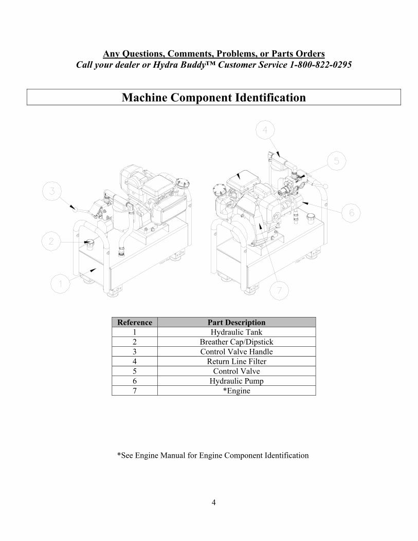
Machine Component Identification
Reference Part Description 1 Hydraulic Tank 2 Breather Cap/Dipstick 3 Control Valve Handle 4 Return Line Filter 5 Control Valve 6 Hydraulic Pump 7 *Engine
*See Engine Manual for Engine Component Identification

5
Specifications Engine .................. Honda GC160 (item# HBH13GC)/Honda GX160 (item# HBH13GX)/Honda GX270 (item#
HBHXL13GX)
Engine Oil Type…………………………………………………Use Engine Manufacturer’s Recommended Oil
Pump Capacity ............................................................................................................................................. 7 GPM
Pump Displacement ....................................................................................................................................... 7.4 cc
Pump Ports ..................................................................................................................................... 1 /2”-14 O-Ring
Pump Rotation Direction ............................................................................................................ Counterclockwise
Hydraulic Fluid Type............................................................................................ AW32, ASLE H-150 or ISO 32
Hydraulic Tank Volume ..................... 5.6 gal (item# HBH13GC & HBH13GX)/10.3 gal (item# HBHXL13GX)
Hydraulic Tank Material ........................................................................................................................ 3/16” Steel
Hydraulic Tank Drain Port ........................................................................................................................ 1/2” NPT
Hydraulic Valve PSI Rating............ 900 PSI (item# HBH13GC & HBH13GX)/1500 PSI (item# HBHXL13GX)
Hydraulic Valve Type .......................................................................... One-Way Detent, One-Way Spring Return
Hydraulic Valve Inlet ............................................................................................................................ 3/4-14 NPT
Hydraulic Valve Outlet ......................................................................................................................... 3/4-14 NPT
Filter Type or replacement ....................................... Parker 12AT25CN25BBN or Hydra Buddy™ Part #787680
Quick Disconnect Fittings....................................................................................................... ISO 7241-1 Series A

6
Safety Hazard Signal Word Definitions
This is the safety alert symbol. It is used to alert you to potential personal injury hazards. Obey all safety messages that follow this symbol to avoid possible injury or death.
DANGER DANGER (red) indicates a hazardous situation, which if not avoided, will result in death or serious injury.
WARNING WARNING (orange) indicates a hazardous situation, which if not avoided, could result in death or serious injury.
CAUTION CAUTION (yellow), used with the safety alert symbol, indicates a hazardous situation, which if not avoided, could result in minor or moderate injury.
CAUTION CAUTION (yellow), without the safety alert symbol, is used to address practices not related to personal injury.
NOTICE NOTICE is used to address practices not related to personal injury.

7
Safety Decal Locations
WARNING ALWAYS make sure safety labels are in place and in good condition. If a safety label is missing or not legible, order new labels from Hydra Buddy™ Customer Service at 1-800-822-0295.
Reference Part Number Part Description Model 1
In Decal Set # 787383
Control Handle Operation # 1 All 2 Carbon Monoxide Warning All 3 Fire Hazard Warning All
4 788400
Throttle Operation HBH13GC, HBH13GX
788401 HBHXL13GX
5 788402
Choke/Gas Shut-off Operation HBH13GC, HBH13GX
788403 HBHXL13GX 6
In Decal Set # 787383
Muffler Warning All7 Inspect Lubricate All8 Control Handle Operation # 2 All9 Hydraulic Fill All10 Hydraulic Fluid Warning All
8
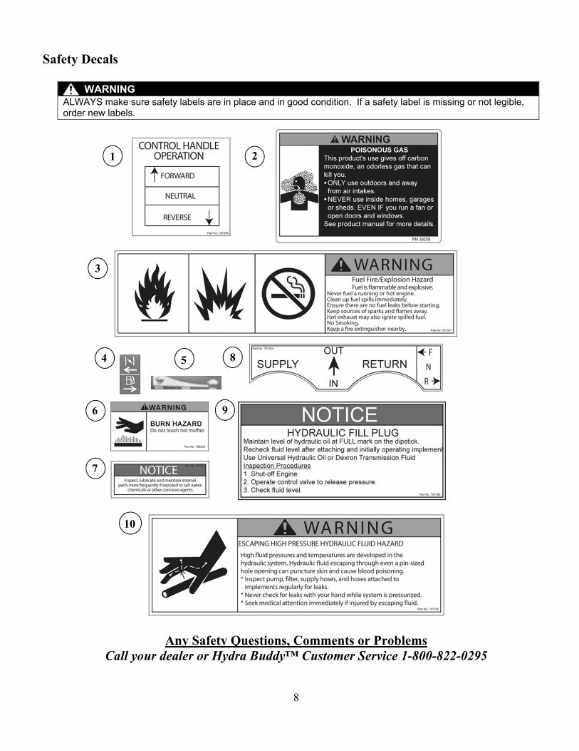
Safety Decals
WARNING ALWAYS make sure safety labels are in place and in good condition. If a safety label is missing or not legible, order new labels.
Any Safety Questions, Comments or Problems Call your dealer or Hydra Buddy™ Customer Service 1-800-822-0295
1 2
3
4 5
6
7
9
10
8

9
Operation
Pre-Start Checklist
CAUTION: No Oil in Engine Crankcase Add the correct amount of oil to engine crankcase or engine will be damaged beyond repair.
CAUTION: No Hydraulic Oil in Tank Add the correct amount of hydraulic oil to the reservoir before use.
1. Install rubber feet to the bottom of the tank assembly 2. Check / add engine crankcase oil 3. Check / add hydraulic oil 4. Prime hydraulic pump (with engine off) 5. Inspect hydraulic system (with engine off) 6. Check Implement Hydraulic System 7. Fill engine gasoline tank (upper tank) 8. Inspect fuel system for leaks (with engine off)
These procedures are discussed in detail below:
1. Install rubber feet to the bottom of the tank assembly Align the holes in the rubber feet with the holes in the hydraulic tank brackets. Insert the supplied 5/16” x 1” bolts through the holes in the feet up into the hydraulic tank brackets. Secure the feet and bolts using the supplied 5/16” nyloc nuts.
5/16” Nyloc Nut
Rubber Feet
5/16” X 1 Bolt

10
Operation (Continued) 2. Check / add engine crankcase oil
Check the oil level daily using the dipstick and add oil as needed. Using a funnel, add oil up to the FULL mark on the dipstick with the recommended oil type for your
engine and expected ambient conditions. Replace engine crankcase fill cap to finger tight. (See engine Owner’s Manual for oil type and capacity, and more detailed oil check/fill instructions.)
3. Check / add hydraulic oil Remove hydraulic oil fill cap. Verify that the oil is at the FULL mark on the dipstick on the hydraulic
reservoir. Do not thread in dipstick when checking oil level. If hydraulic oil level is low: Add 10 wt. AW32, ASLE H-150, or ISO 32 oil up to the FULL mark on
dipstick. Replace hydraulic tank fill cap to finger tight.
WARNING: Hot Oil Hazard NEVER remove the hydraulic oil fill cap when the engine is running or hot. Hot oil can escape causing severe burns. Allow the Hydraulic Power Pack to cool completely before removing hydraulic oil fill cap.
NOTICE: Attached Implement Hydraulic Oil: Refer to the attached implement owner’s manual for its recommended oil. If you are using an implement that requires different oil, it may be incompatible with the above recommended oil, contact Hydra Buddy™.
4. Prime hydraulic pump (with engine off) Remove spark plug wire from engine spark plug. Pull the engine recoil start several times to prime the hydraulic pump with hydraulic oil. Replace spark plug wire on engine spark plug.
5. Inspect hydraulic system (with engine off) Visually inspect all Hydraulic Power Pack hoses, tubing, clamps/fittings, pump, and cylinder for
cracks, fraying, kinks, or other damage. Check all components for oily residue, which may indicate a leak. Do NOT operate the Hydraulic Power Pack if there is any indication of damage or oily residue.

11
Operation (Continued) 6. Check implement hydraulic system
Check hydraulic system and lines of the implement to be attached to the Hydraulic Power Pack. Small leaks in hydraulic lines can be an indication of catastrophic failure in the near future. The life of hydraulic hoses may be from a few months to a few years, depending on use and storage patterns.
WARNING: Pressurized Fluid Hazard
High fluid pressures and temperatures are developed in Hydraulic Power Packs.
NEVER check for leaks with your hand. Leaks can be located by holding a piece of cardboard or wood (at least two feet long) with your hand at one end and passing the other end over the suspected area (wear eye protection). Look for discoloration on the cardboard or wood.
STOP the engine, disconnect the spark plug, and move all control valve handles back and forth to relieve pressure before changing or adjusting hydraulic system components such as hoses, tubing, fittings, or other components.
NEVER adjust the pressure setting of the pump or valve Hydraulic fluid escaping through a pin-sized opening can burn or puncture skin, resulting in wounds that could cause blood poisoning, infection, disability, gangrene, amputation, or death.
If injured by escaping fluid, no matter how small the wound is, see a doctor at once. A typical injection injury may be a small puncture wound that does not look serious. However, severe infection or reaction can result if proper medical treatment is not administered immediately by a doctor who is familiar with injection injuries.
7. Fill engine gasoline tank (the upper tank) Check gasoline tank level. Fill tank with fresh unleaded gasoline from a portable container.
WARNING: Gasoline Vapor Hazard While Fueling Gasoline is highly flammable and explosive. Heat, sparks, and flames can ignite gasoline vapors which spread over a large area during fueling. A flash fire ignition and/or explosion will likely result in serious injury or death. The following conditions could result in gasoline ignition/explosion:
Refueling and refueling spills Gas vapor collection inside enclosures Static electric sparks Sparks from electric wiring, batteries, or running engines Sources of heat (such as a hot engine exhaust) Open flames, including pilot lights
8. Inspect fuel system for leaks (with engine off) Inspect the entire fuel system. Look for signs of: leaks or deterioration; chafed or spongy fuel hose; loose
connections; loose or missing fuel hose clamps; damaged gasoline tank; or a defective gasoline shut-off valve.
WARNING: Fuel Leak Hazard
A leaking fuel line or spilled fuel no matter how small can be the source of a fire or explosion when starting or operating the engine.
If Hydraulic Power Pack is in an enclosed area and you smell gas, DO NOT start engine! DO NOT light a match. DO NOT flip on an electrical switch.
Exit area immediately leaving doors open and call fire department.

12
Starting and Warm-up Before Use 1. Place the Hydraulic valve handle in the neutral (center) position.
2. Start the engine per the manufacturer’s instructions.
3. Once the engine has started, move the throttle down to the mid-range position and allow the engine to run for ten (10) minutes to warm engine and hydraulic oil.
4. Turn engine off. 5. Clear line pressure by moving the Hydraulic Power Pack valve to the forward position for
four (4) or five (5) seconds, then to the reverse position for four (4) or five (5) seconds to relieve pressure.
6. Attach implement’s hydraulic hoses. Your Hydraulic Power Pack is now ready for attachment to an implement.
WARNING: Personal Protective Equipment Never use the Hydraulic Power Pack or any powered equipment without proper protective equipment, such as eye protection.

13
Using Hydraulic Motor Implement NOTICE: Match Quick Disconnect Couplers The Hydraulic Power Pack is equipped with1/2” quick-disconnect couplers. If necessary, replace with implement-matching couplers. Hydra Buddy™ does not recommend adapters; they may restrict flow and limit operation.
1. Connect Hoses (Engine Off) Before connecting your implement hoses to the Hydraulic Power Pack, you must determine which hose
is the pressure or forward acting hose. Consult your implement owner’s manual or labels to determine which hose is the “SUPPLY” hose.
Once the implement SUPPLY port has been determined, connect this “SUPPLY” hose to Hydraulic Power Pack’s port labeled “SUPPLY” (port closest to the engine). Connect the implements RETURN line to Hydraulic Power Pack’s port labeled “RETURN”.
2. Normal Operation Mode: Place the control valve handle in the center (neutral) position. Re-start warmed-up engine per the manufacturer’s instructions. Place the engine throttle control lever in the fast position. Push the valve handle slowly inward until it locks in position and implement is operational. TO STOP: You must manually pull the handle back to the center (neutral) position NOTICE: When using the Hydraulic Power Pack to auger corn or beans, position the unit to the furthest upwind point from the auger intake or chaff cleaner if possible. This will prevent chaff from plugging the engine air filter and cooling fins.
3. Reverse Operation Mode: (See Caution below) To reverse the direction of an attached motor: Pull the valve handle outward to the center (neutral) position. Wait until the attachment motor comes to a complete STOP. Pull the valve handle out slowly and hold it. NOTICE: As a safety precaution, the reverse valve position is spring loaded to return to the center (neutral) position when released. You must hold the valve handle in the reverse position for reverse operation.
CAUTION: Reverse Operation Equipment Damage The Hydraulic Power Pack has a bidirectional valve that allows you to reverse the direction of an implement motor (or pump). Before using the reverse feature, consult your implement owner’s manual to make sure the motor (or pump) can be reversed. Using reverse oil flow in a non-reversing pump or motor can result in damage to your implement.
4. Stopping or Removing Attached Implement with Hydraulic Motor: To turn off the motor, first place the valve handle in the center (neutral) position. Turn the engine off. Allow the motor to come to a complete stop. Operate any switches or valves on the motor to relieve pressure. Move the Hydraulic Power Pack valve handle to the forward position for four (4) to five (5) seconds,
then to the reverse position for four (4) to five (5) seconds to relieve pressure. Operate any other valves or switches on accessory items to relieve pressure. Disconnect the hoses.

14
Using Hydraulic Cylinder Implement NOTICE: Match Quick Disconnect Couplers The Hydraulic Power Pack is equipped with 1/2” quick-disconnect couplers. If necessary, replace with implement-matching couplers. Hydra Buddy™ does not recommend adapters; they may restrict flow and limit operation.
1. Connect Hoses: Before connecting your implement hoses to the Hydraulic Power Pack, you must determine which hose
is the pressure or forward acting hose. Consult your implement owner’s manual or labels to determine which hose is the “SUPPLY” hose.
Once the implement SUPPLY port has been determined, connect the “SUPPLY” hose to Hydraulic Power Pack’s port labeled “SUPPLY”. Connect the implements RETURN line to Hydraulic Power Pack’s port labeled “RETURN”.
WARNING: Crush Hazard The Hydraulic Power Pack valve does not have a positive locking device to hold the cylinder in position. Always use a mechanical lock to prevent the cylinder from creeping/drifting.
WARNING Applications with large cylinders can excessively deplete the Hydraulic Power Pack’s hydraulic tank.
DO NOT use this unit in applications where more than 75% of the hydraulic fluid is purged from the hydraulic tank or with a cylinder storing a larger oil reserve than the Hydraulic Power Pack.
DO NOT attempt to add more hydraulic fluid during operation to extend the hydraulic capacity.
Failure to follow these warnings could result in damage to property/equipment, personal injury, and death in serious cases.
2. Start Engine: Place the control valve handle in the center (neutral) position. Re-start warmed-up engine per the manufacturer’s instructions. Place the engine throttle control lever in the fast position. Push the valve handle slowly inward until it locks in position and implement is operational
3. Normal Operation: To raise the cylinder, push the handle inward until the desired height is reached, then return the valve
handle to the center (neutral) position. Important: block or lock the implement at the desired height. If the implement is not locked into position, the Hydraulic Power Pack will allow the cylinder to drift.
To lower the cylinder, pull the handle outward until the desired height is reached, then release the handle (it will automatically return to the center position).
NOTICE: When the valve handle is pushed inward, it locks in place. You must then pull the handle back to the center (neutral) position to stop cylinder movement.
4. To Stop or Remove Attached Implement with Hydraulic Cylinder(s): To remove the unit, first place the implement cylinder in the fully retracted position (so the rod is inside
the cylinder barrel). Then, place the valve handle in the center (neutral) position. Turn engine off. Move the valve handle to the forward position for four (4) to five (5) seconds, then to the reverse
position for four (4) to five (5) seconds to release system pressure. Disconnect the hoses.

15
Refueling WARNING: Fire Hazard
Allow the engine to cool for at least five (5) minutes before refueling, moving to storage or transporting. A hot engine can be a fire hazard.
Refueling at Work Sites: Before removing gas cap, turn engine off and allow to cool for at least FIVE (5) minutes. Remove gasoline cap Use only a UL-approved portable gasoline container to transfer the gasoline to the Hydraulic Power
Pack’s tank Add gasoline through the fill opening Clean up gasoline spills /splashes immediately Replace gasoline cap securely If possible, move the Hydraulic Power Pack away from spilled gasoline on the ground Wipe up spilled gasoline and wait five (5) minutes for excess gasoline to evaporate before starting
engine Gasoline soaked rags are flammable and should be disposed of properly If gasoline is spilled on your skin or clothes, wash skin and change clothes immediately Store extra gasoline in a cool, dry place in a UL listed, tightly sealed container
Refueling at Gas Stations: WARNING: Static Electric Spark Hazard
A static electric spark can explosively ignite gasoline vapor, resulting in a flash fire that could cause serious injury or death. See “Special Safety Information on Static Electricity” at end of this manual.
Use only a UL listed portable gasoline containers Never fill the gasoline tank directly from the fuel pump. The tank is not grounded and high velocity
flow from the pump can cause static electricity build-up. Use a portable container made of metal or conductive plastic. This is preferred because it dissipates
static charge to ground more readily. ALWAYS place container on the ground to be filled. Never fill a portable gasoline container while it
is sitting inside a vehicle, trailer, trunk, or pick-up truck bed. Keep nozzle in contact with container while filling. Do not use a nozzle lock-open device.

16
Storing Allow engine to cool before inspecting and storing
1. Inspect for worn or damaged parts 2. Choose a covered storage location 3. Start engine every 4 weeks; -OR- 4. Prepare engine for long-term (seasonal) storage if needed.
1. Inspect for worn or damaged parts: Inspect the Hydraulic Power Pack for worn or damaged parts and tighten any nuts or screws that may have become loose. Check for any fuel or hydraulic system leaks.
2. Choose a covered storage location: Store the Hydraulic Power Pack in a location that is:
Clean and dry. Away from sources of heat, open flames, sparks, and pilot lights, even if the gas tank is empty.
(Residual gasoline fumes can still ignite) Away from extreme high or low temperatures. Cover for extra protection.
WARNING: Stored Gasoline Vapor Fire Hazard
Gasoline is highly flammable and explosive. Drain the fuel into an approved container OUTDOORS and far away from open flame.
NEVER store an engine with fuel in the tank indoors or in poorly ventilated spaces where fuel vapor can come in contact with:
Static electric sparks; Sparks from electric wiring, batteries, or running engines; Sources of heat (such as hot engine or exhaust); Open flames, including pilot lights.
3. Start engine every 4 weeks: For future easy starting and to minimize maintenance requirements, the Hydraulic Power Pack should be started at least every four weeks and run for 10 to 15 minutes.
Monthly exercising of the engine will dry out any moisture that has accumulated, lubricate cylinders, and clean out old gas in the carburetor. Moisture, old gas, and dry mechanical parts cause deterioration in stored engines.
4. Prepare engine for long-term (seasonal) storage if needed: If you will not be able to start the engine regularly, you must prepare the engine for long term storage to prevent gum deposits from forming and causing malfunction of the engine.
Prepare engine for long-term storage by either removing all gasoline from the tank and carburetor, OR by adding fuel stabilizer to the gasoline. Follow fuel stabilizer manufacturer’s instructions, which usually include these steps:

17
Storing (Continued)
Ensure gas tank is full. Add fuel stabilizer to fuel tank. Run engine at least 10 minutes after adding stabilizer to allow it to enter the fuel system. Shut off engine. Disconnect spark plug wire and remove spark plug. Add one teaspoon oil through spark plug hole. Place rag over spark plug hole and turn starter (or pull the recoil) a few times to lubricate the
combustion chamber. Replace spark plug, but do not reconnect the spark plug wire.

18
Maintenance & Repair
Regular Maintenance Perform regular maintenance to keep the Hydraulic Power Pack in safe and functional working condition.
WARNING ALWAYS shut off the engine, make sure the engine is cool, and disconnect the spark plug before cleaning, adjusting, or servicing the Hydraulic Power Pack.
1. Follow safety rules: Turn off the Hydraulic Power Pack. To prevent accidental starting, always turn off the Hydraulic Power Pack and remove spark plug or spark plug wire.
Avoid burns. Muffler, crankcase oil and hydraulic oil will remain hot for several minutes even after unit is stopped. Allow to cool before servicing.
2. Perform periodic engine maintenance: Perform engine maintenance as specified in the engine owner’s manual. Engine maintenance items include:
Oil and oil filter changing Air filter check/replacement Spark plug cleaning and replacement Fuel filter check/replacement Fuel tank cleaning
3. Inspect fuel system/check for leaks: Inspect the fuel system and check for leaks on a regular basis.
Look for: signs of leaks or deterioration, chafed or spongy fuel hose, loose connections, loose or missing fuel hose clamps, damaged gasoline tank, or defective gasoline shut-off valve.
WARNING: Fuel Leak Hazard A leaking fuel line no matter how small can be the source of a fire or explosion when starting or operating the engine.
4. Inspect hydraulic system/check for leaks: The hydraulic system (hoses and pump) should be carefully inspected before each use. Also inspect the mechanical parts at the same time. Make sure all hoses, clamps, nuts, bolts, fittings, etc., are properly installed and tightened.
Always replace frayed, kinked, or cracked hoses and/or other damaged hydraulic components with Hydra Buddy™ authorized parts and components specified in the “Parts List” section of this manual.
Should it become necessary to loosen or remove any hydraulic fitting or hose, be sure to relieve all hydraulic pressure by shutting off the engine, removing spark plug wire, and moving the valve control handle back and forth several times.
WARNING: Hot Oil Hazard NEVER remove the hydraulic oil fill cap when the engine is running or hot. Hot oil can escape causing severe burns. Allow the Hydraulic Power Pack to cool completely before removing hydraulic oil fill cap.

19
Maintenance & Repair (Continued) 5. Hydraulic oil & filter change: Hydra Buddy™ recommends an oil change every 100 hours of operation. Add 10 wt. AW32, ASLE H-150, or ISO 32 oil to 1” full mark on the dipstick.
WARNING Never run the Hydraulic Power Pack unless the hydraulic oil tank is at the full mark on the dipstick.
Repairs and Parts
Repairs. Major service, including the installation or replacement of parts, should be performed only by a qualified technician.
Replacement parts. If a part needs replacement, only use factory approved repair parts. Replacement parts from secondary suppliers (not original Hydra Buddy™ replacement parts) can lead to product damage and/or personal injury, and will void the warranty. Also, replacement parts that do not meet specifications may result in a safety hazard or poor operation of the Hydraulic Power Pack. Obtain factory-approved parts from Hydra Buddy™ Customer Service at 1-800-822-0295.
Maintenance Schedule
Type of Maintenance Frequency Check Hydraulic Oil Level Daily
Check Hydraulic Oil is Clean Daily Change Hydraulic Oil Annually/100 hrs.
Clean Magnetic Drain Plug Each Hydraulic Oil Change Replace Return Line Filter First 50 hrs. / 250 hrs. Check Coupling Assembly 250 hrs.

20
Troubleshooting WARNING
Before troubleshooting or attempting to service, read the following safety instructions to avoid serious injury to the operator or bystanders from moving parts that can crush or cut, burns, fire or explosion, or escaping high pressure hydraulic fluid.
Important Safety Instructions: Engine off. Always make sure the engine is off before cleaning, repairing or adjusting the Hydraulic Power Pack, except as recommended by the manufacturer.
Hydraulic safety. High fluid pressures and temperatures are developed in the Hydraulic Power Pack . Hydraulic fluid escaping through a pin hole sized opening can burn or puncture skin, resulting in wounds that could cause blood poisoning, infection, disability, gangrene, amputation, or death. Therefore, the following instructions should be heeded at all times when inspecting or servicing the hydraulic components of the log splitter:
Stop the engine, disconnect the spark plug, and move all control valve handles back and forth to relieve pressure before changing or adjusting hydraulic components such as hoses, tubing, fittings, or other components.
Do not remove the hydraulic oil fill cap when the engine is running. Hot oil can escape causing severe burns. Allow the log splitter to cool completely before removing the hydraulic oil fill cap.
Do not adjust the pressure setting to the pump or valve.
Do not check for leaks with your hands. Leaks can be located by holding a piece of cardboard or wood (at least 2 feet long) with your hand at one end and passing the other end suspected area (wear eye protection). Look for discoloration of the cardboard or wood.
If injured by escaping fluid, no matter how small the wound is, see a doctor at once. A typical injection injury may be a small puncture that does not look serious. However, severe infection or reaction can result if proper medical treatment is not administered immediately by a doctor who is familiar will injection injuries.

21
Troubleshooting (Continued)
Problem Engine stalls when valve engaged Cause: 1, 2, 4, 22, 24 Motor or cylinder moves slow Cause: 1, 3, 5, 7, 22, 24, 25Engine appears to be seized Cause: 1, 2, 6, 7, 8, 24Motor or cylinder moves erratically Cause: 3, 9, 10, 11, 12, 18, 19, 20, 22, 23, 24, 25Engine won’t turn or stalls at no load Cause: 10, 14, 16, 21, 23, 24Pump shaft seal leaks Cause: 9, 11, 12, 13, 14, 15, 16, 17
Cause Solution 1. Bad connection at hydraulic coupler. (E, J) A. Keep oil tank full and clean. 2. Lines reversed. (C) B. Clean vent hole. 3. Worn ball seat on coupler. (E) C. Slowly reverse position of valve handle. If implement
moves shut down and reverse lines. 4. Auger plugged or jammed. D. Shut engine off, remove debris. 5. Lower hydraulic oil in reservoir. (A, H) E. Shut off engine, remove and inspect the hydraulic
coupler for worn area, if found remove and replace. 6. Pressure lock. (B, D, E, J) F. Flush and clean hydraulic system. 7. Defective pump. (L) G. Shut down engine and inspect oil levels. Fill to
adequate levels or change. 8. Defective engine. (L) H. Remove pump and check to see that it moves freely. 9. Air in system (A, I) I. Shut engine off then restart. 10. Insufficient oil to pump. (A, E, F, G, H, J) J. Check hoses for damage and correct placement. 11. Tank breather plugged. (B) K. Precise alignment of engine and pump is necessary
(do not force). 12. Shaft seal improperly vented. (L) L. Return component to dealer/manufacture for
necessary repairs. 13. Leakage through pump check valve. (L) 14. Pump high pressure gear set damaged. (L) 15. Pump gear set worn. (L) 16. Pump seized-up. (H, L) 17. Drive shaft broken. (L) 18. Internal leakage in directional valve. (F, H, L) 19. Directional valve damaged. (L) 20. Obstruction in directional valve. (F, H, L) 21. Obstruction in hydraulic lines. (F, H, J, L) 22. Weak engine-low horsepower. (D, L) 23. Low engine speed. (D, L) 24. Improper engine/pump alignment. (K, L) 25. Shaft coupling loose. (K, L)

22
Summary of Important Safety Information This section provides a summary of the various safety procedures and measures that have been presented through the manual. Keep this summary handy and refer to it to refresh your memory about how to safely use your Hydraulic Power Pack.
WARNING Carefully read and make sure you understand the following safety information before using the Hydraulic Power Pack. Improper use or maintenance of the Hydraulic Power Pack can result in serious injury or death to the operator and/or bystanders from fire/explosion, carbon monoxide poisoning, injection injuries, or burns.
General Read manual. Read this Owner’s Manual and the engine Owner’s Manual completely before attempting to use and
service the Hydraulic Power Pack. Serious injury or death can result if safety instructions are not followed.
Instruct operators. The Hydraulic Power Pack owner or rental company must instruct all operators in safe Hydraulic Power Pack set-up and operation. Do not allow anyone to operate the Hydraulic Power Pack who has not read the Owner’s Manual and been instructed in its safe use. Make sure Owner’s Manual is within the attached storage tube on the Hydraulic Power Pack.
Adults only. Only trained adults should operate and service the Hydraulic Power Pack. Do not let children operate.
Under the influence. Never operate, or let anyone else operate, the Hydraulic Power Pack while under the influence of alcohol, drugs, or medication.
Intended use. Carefully read about and understand the intended use of this Hydraulic Power Pack. Do not use for other purposes, as unforeseen hazards or equipment damage may result.
Controls and safety labels. Learn how to use the machine and its controls. Understand and follow all safety labels.
Prohibition Against Modifications Never modify or alter the Hydraulic Power Pack in any way. Modifications can create serious safety hazards and will
also void the warranty.
Fuel/exhaust system. Never modify the exhaust system, fuel tanks, or fuel lines. Carbon monoxide poisoning, fire, or explosion could result.
Pressure setting. Never increase the pressure setting of the pump or control valve.
Safety – Before Use Know how to operate. Be thoroughly familiar with all controls and with the proper and safe use of the equipment.
Know how to stop and de-energize the Hydraulic Power Pack quickly if needed.
Getting Ready Operate OUTSIDE only – dangerous carbon monoxide exhaust! Hydraulic Power Packs give off carbon monoxide
exhaust, a poisonous gas that can kill. You CANNOT smell it, see it, or taste it. ONLY run Hydraulic Power Pack OUTDOORS and away from building air intakes. NEVER run Hydraulic Power Pack inside homes, garages, sheds, or other semi-enclosed spaces. These spaces can trap poisonous gases.
Cooling ventilation. The Hydraulic Power Pack needs adequate, unobstructed flow of air to allow for proper cooling of engine. Do not allow debris to accumulate and block airflow.
Transporting. When transporting, take precautions to make sure Hydraulic Power Pack will not tip over and cause a fuel leak hazard. Tie down in upright position during transportation.

23
Summary of Important Safety Information (Continued) Hot exhaust – fires. Exhaust from engine can be extremely hot and cause fire. Position muffler at least 7 feet from
combustible objects during operation.
Fire extinguisher. Keeping a fire extinguisher rated “ABC” by the National Fire Protection Association nearby is always recommended when using gasoline-operated machinery. Keep it properly charged and be familiar with its use.
Personal Protective Equipment Hearing protection. The use of earplugs or other hearing protection device is recommended for those in close proximity
to the Hydraulic Power Pack while it is operating.
Eye protection. Wear ANSI-approved eye protection when operating the Hydraulic Power Pack.
Loose/dangling. Loose or dangling apparel, jewelry or hair can become entangled in moving parts. Never wear jewelry or loose-fitting clothing when operating the Hydraulic Power Pack and attached implements.
Gasoline Safety Gasoline is highly flammable and explosive. You can be burned or seriously injured. Use extreme care when handling
gasoline.
Fuel outdoors. Fill fuel tank outdoors – never indoors. Gasoline vapors can ignite if they collect inside an enclosure. Explosion can result.
Use approved container. Never pump fuel directly into engine at service station. Static charge can build and ignite fuel. Use a UL listed fuel container to transfer gasoline to the engine.
Running/hot engine. A running engine is hot enough to ignite fuel. Never add fuel or remove gas cap if engine is running or still hot. Stop the engine and allow to cool at least five minutes before adding fuel.
Heat/flames/sparks. Keep sources of heat, flame, or sparks away while adding fuel.
Don’t fill to the top. DO NOT overfill the gasoline tank. Allow at least 1” of empty space below the fill neck to allow for fuel expansion and operation on slopes.
Replace cap. Replace gasoline cap securely before starting engine.
Spills. Clean up fuel spills immediately. Move Hydraulic Power Pack away from spilled fuel on the ground. Wipe fuel off engine and wait 5 minutes for excess fuel to evaporate before starting engine. Gasoline-soaked rags should be disposed of properly.
On skin/clothes. If gasoline is spilled on your skin or clothes, wash skin and change clothes immediately.
Inspect fuel system. Check fuel system on a regular basis. Look for signs of leaks, deterioration, chafed or spongy fuel hose, loose or missing fuel hose clamps, damaged fuel tank, or a defective fuel shut-off valve. Do not start Hydraulic Power Pack until needed repairs have been completed.
Gasoline storage. Store gasoline in a cool, dry place in a UL listed, tightly sealed container away from children.
Hydraulic System Safety Check the hydraulic system (hoses, tubing, clamps/fittings, pump, and cylinder) carefully before each use. Do not
operate the Hydraulic Power Pack or its attachments with frayed, kinked, cracked, or damaged hydraulic hoses, fittings, or tubing.
High fluid pressures and temperatures are developed in Hydraulic Power Packs. Hydraulic fluid escaping through a pin-size opening can burn or puncture skin, resulting in wounds that could cause blood poisoning, infection, disability, gangrene, amputation, or death.
Do not remove the hydraulic oil fill cap when the engine is running. Hot oil can escape causing severe burns. Allow Hydraulic Power Pack to cool completely before removing hydraulic oil fill cap.

24
Summary of Important Safety Information (Continued)
Do not adjust the pressure setting of the pump or valve.
Do not check for leaks with your hand. Leaks can be located by holding a piece of cardboard or wood (at least two feet long) with your hand at one end and passing the other end over the suspected area (wear eye protection). Look for discoloration of the cardboard or wood.
Stop the engine, disconnect the spark plug, and move all control valve handles back and forth to relieve pressure before changing or adjusting hydraulic system components such as hoses, tubing, fittings, or other components.
If injured by escaping fluid, no matter how small the wound is, see a doctor at once. A typical injection injury may be a small puncture wound that does not look serious. However, severe infection or reaction can result if proper medical treatment is not administered immediately by a doctor who is familiar with injection injuries.
Safety – During Use Safety equipment/controls. Always operate the Hydraulic Power Pack with all controls properly adjusted for safe
operation.
Check for gasoline leak before starting. After opening gasoline valve, smell for gasoline before starting engine. If you smell gasoline, DO NOT start engine. DO NOT light a match. DO NOT flip on an electrical switch. Exit area immediately and call fire department.
Operating speed. Always operate the Hydraulic Power Pack at the manufacturer’s recommended speed. The maximum speed of the engine pump is preset within safe limits.
Know how to stop. Know how to stop the Hydraulic Power Pack quickly if needed. Do the following in order until unit is stopped. (1) First, use on/off switch on engine. (2) Alternatively, engage full choke to flood engine. (3) Pull spark plug wire using an electrically insulated tool or glove.
Damaged. Do not operate the Hydraulic Power Pack with damaged, missing, incorrectly adjusted, or broken parts.
Carbon monoxide exhaust. The running engine gives off carbon monoxide, a poisonous gas that can kill you. You CANNOT smell it, see it, or taste it. If you start to feel sick, dizzy, or weak while using the Hydraulic Power Pack, shut off the engine and get to fresh air RIGHT AWAY. See a doctor. You may have carbon monoxide poisoning.
Other exhaust dangers. This product contains or emits chemicals known to the State of California to cause cancer, birth defects or other reproductive harm. Avoid inhalation of exhaust.
Smoking/sparks. Never smoke near the running Hydraulic Power Pack, and never operate near sources of sparks or flames.
Hot muffler. Never touch hot muffler or hot exhaust manifold. Exhaust and engine parts can be very hot and will burn you.
Moving parts. Keep hands, feet, and apparel away from moving parts of unit or its attachments.
Refueling. DO NOT refuel the engine until it has cooled at least five minutes.
Malfunction during operation. Always shut the machine off if any unusual noise or vibration occurs.
Vibration. Overexposure to any machine vibration daily may lead to circulatory or nerve damage.
Adjusting/repairing. Always turn off Hydraulic Power Pack and remove spark plug or spark plug wire before working on the Hydraulic Power Pack to prevent accidental starting.

25
Summary of Important Safety Information (Continued)
Safety – After Use Cool engine before storing. Let engine cool for at least five (5) minutes before storing. A hot engine can be a fire
hazard.
Shut off fuel supply. Make sure gasoline shut-off lever is in the closed position (to the left).
Prevent accidental starting. When Hydraulic Power Pack is not in use, remove key from starter (electric start engines) and secure in a safe location, or remove spark plug in order to ensure that Hydraulic Power Pack cannot be started in a storage location or by untrained persons.
Storage location. Store the Hydraulic Power Pack in a dry location away from sources of heat, open flames, sparks or pilot lights, such as water heaters, space heaters, furnaces, clothes dryers, or other gas appliances, EVEN IF the Hydraulic Power Pack’s gas tank is empty. Residual gasoline could ignite.
Exercise regularly. Exercise the Hydraulic Power Pack’s engine every four (4) weeks to dry out moisture that accumulates in the windings. If engine cannot be exercised on a regular basis, prepare it for long-term (seasonal) storage.
Safety – Inspection/Maintenance Inspect and maintain your Hydraulic Power Pack on a regular basis and repair as needed to keep it in safe working
condition:
Turn off Hydraulic Power Pack. Always turn off Hydraulic Power Pack and remove spark plug or spark plug wire before working on the engine or Hydraulic Power Pack to prevent accidental starting.
Burns. Do not touch hot muffler. Muffler will be hot even if unit is stopped. Allow unit to cool before servicing.
Burns. Do not remove hydraulic oil fill cap when the engine is running or hot. Hot oil can escape and cause severe burns. Allow Hydraulic Power Pack to cool completely before removing hydraulic oil fill cap.
Replacement parts. If a part needs replacement, only use parts that meet the manufacturer’s specifications. Replacement parts that do not meet specifications may result in a safety hazard or poor operation of the Hydraulic Power Pack and will void the warranty.
Any Safety Questions, Comments or Problems Call your dealer or Hydra Buddy™ Customer Service 1-800-822-0295

26
Special Safety Information on Static Electricity
Accidents Involving Static Electricity Static electricity and filling gasoline containers. Static electricity can initiate from ungrounded gasoline tanks or
containers, from flowing gasoline, and from persons carrying a static electric charge.
Static electricity on numerous occasions has explosively ignited gasoline vapors that were present during fueling processes, resulting in serious burns to nearby persons. To avoid static electricity while fueling, certain steps must be followed before and during the fueling process in order to minimize and safely dissipate static charge build-up.
Filling Portable Containers at Service Stations: Use a portable container to fill Hydraulic Power Pack tank. Never fill the Hydraulic Power Pack’s gasoline tank
directly from the service station’s fuel dispenser pump – the Hydraulic Power Pack’s tank is not grounded and the high velocity flow of gasoline from a fuel pump can cause static electric build-up. Use an approved portable container to transfer gasoline to the Hydraulic Power Pack’s tank.
Use a portable container made of metal or conductive plastic. It will dissipate charge to ground more readily.
Fill container on the ground. Never fill the portable gasoline container while it is sitting inside a vehicle, trailer, trunk, or pick-up truck bed. ALWAYS place container on the ground to be filled.
Touch a grounded metal object before starting. Always dissipate static charge from your body before beginning the fueling process by touching a grounded metal object that is a safe distance away from fuel sources.
Keep nozzle in contact with container. Keep fuel dispenser nozzle in contact with the portable container at all times while filling at a service station. Do not use the nozzle lock-open device on the dispenser hose.
About static electricity and fueling Many common objects can accumulate and retain a static electric charge. Objects made of non-conductive materials
(e.g., plastics) easily accumulate and retain static electric charge, as can objects made of conductive material (e.g., metal, water) if they are not electrically grounded. The static electric charge on an object, such as a human body or plastic fuel tank/container, can reach as high as several thousand volts!
A static electric spark can be generated if the static electric charge stored on an object “jumps” to another, less charged object. Such a spark can ignite invisible gasoline vapors that are present during fueling situations.
Typical sources of static electric hazards during fueling The following objects can accumulate a static electric charge and cause an ignition spark in typical fueling situations:
Ungrounded tanks/containers. Any ungrounded fuel tank or container can accumulate a static electric charge as a result of contact with other objects or friction during transportation. This static electricity can discharge as a spark to the grounded gasoline dispenser nozzle, as the nozzle is first brought close to the tank/container at the beginning of the fueling process.
Flowing gasoline. Most people are not aware that gasoline accumulates static electric charge while flowing through a hose or pipe. This charge then transfers to and accumulates in the gasoline tank or container that is being filled. The total amount of charge accumulation depends on the amount of gasoline pumped into the container, the speed with which it is pumped, and whether or not the tank/container is grounded. If sufficient static electric charge accumulates in the fuel tank or container during the fueling process, the tank/container may discharge a spark to the grounded gasoline dispenser nozzle.
Persons. A person dispensing the gasoline can carry a static electric charge on their body, typically resulting from contact with their car seat or electronics. The static electricity can discharge as a spark between that person’s hand and either the grounded dispenser nozzle or the fuel tank opening.

27
245000 & 245001 Exploded View – Rev. A

28
HBH13GC, HBH13GX, & HBHXL13GX Parts List - Rev. A Ref # Part Description Qty Used On
1 790629 SMALL HYDRAULIC TANK WELDMENT
1 HBH13GC, HBH13GX
790628 LARGE HYDRAULIC TANK WELDMENT HBHXL13GX
2 GC160 HONDA 5.0HP ENGINE GC160
1 HBH13GC
GX160 HONDA 5.5HP ENGINE GX160 HBH13GX GX270 HONDA 9.0HP ENGINE GX270 HBHXL13GX
3 788844 3/4"X 15" SUCTION HOSE 1 HBH13GC, HBH13GX, HBHXL13GX 4 17141 3/4" HOSE CLAMP 4 HBH13GC, HBH13GX, HBHXL13GX 5 778829 3/4 NPT X 3/4 HOSE BARB 1 HBH13GC, HBH13GX, HBHXL13GX 6 787680 RETURN LINE FILTER ASSEMBLY 1 HBH13GC, HBH13GX, HBHXL13GX 7 787952 REPLACEMENT FILTER CANISTER 1 HBH13GC, HBH13GX, HBHXL13GX 8 777801 NPT12 X JIC12 90 LONG FITTING 1 HBH13GC, HBH13GX, HBHXL13GX 9 787039 3/4-14 NPT X 1-1/16 JIC 1 HBH13GC, HBH13GX, HBHXL13GX
10 787017 HYDRAULIC VALVE – 900 PSI
1 HBH13GC, HBH13GX
787018 HYDRAULIC VALVE – 1500 PSI HBHXL13GX 11 82076 1/4-20 X 1 3/4 BOLT 2 HBH13GC, HBH13GX, HBHXL13GX 12 790655 DECAL, HYDRA BUDDY™ 2 HBH13GC, HBH13GX, HBHXL13GX 13 82222 1/4-20 NYLOC NUT 2 HBH13GC, HBH13GX, HBHXL13GX 14 787044 MALE BOOT QUICK CONNECT 1 HBH13GC, HBH13GX, HBHXL13GX15 787038 3/4-14 NPT X 3/4-16 ORING BOSS 1 HBH13GC, HBH13GX, HBHXL13GX16 787042 1/2" MALE QUICK CONNECT 1 HBH13GC, HBH13GX, HBHXL13GX17 787043 1/2" FEMALE QUICK CONNECT 1 HBH13GC, HBH13GX, HBHXL13GX18 787037 1/2"-14 LONG HEX NIPPLE 2 HBH13GC, HBH13GX, HBHXL13GX19 787045 FEMALE BOOT QUICK CONNECT 1 HBH13GC, HBH13GX, HBHXL13GX
20 82017 5/16-18 X 1 1/2 BOLT
4 HBH13GC, HBH13GX
82018 5/16-18 X 2 BOLT HBHXL13GX 21 82021 5/16 USS FLAT WASHER 4 HBH13GC, HBH13GX, HBHXL13GX22 82100 5/16 SPLIT LOCK WASHER 4 HBH13GC, HBH13GX, HBHXL13GX23 82020 5/16-18 NYLOC NUT 8 HBH13GC, HBH13GX, HBHXL13GX24 82086 5/16-24 X ¾ BOLT 4 HBH13GC, HBH13GX, HBHXL13GX
25 777910 ENGINE COUPLING 3/4"
1 HBH13GC, HBH13GX
777911 ENGINE COUPLING 1” HBHXL13GX
26 787715 3/4 X 4" SUCTION HOSE
1 HBH13GC, HBH13GX
787716 3/4 X 5" SUCTION HOSE HBHXL13GX 27 787352 3/4 NPT X 3/4 BEADED HB 1 HBH13GC, HBH13GX, HBHXL13GX28 790627 VALVE MOUNT PLATE 1 HBH13GC, HBH13GX, HBHXL13GX29 82091 5/16-18 X 1 BOLT 2 HBH13GC, HBH13GX, HBHXL13GX30 787026 HYDRAULIC PUMP 1 HBH13GC, HBH13GX, HBHXL13GX31 777909 PUMP COUPLING 1/2" 1 HBH13GC, HBH13GX, HBHXL13GX32 777912 COUPLING INSERT 1 HBH13GC, HBH13GX, HBHXL13GX33 787048 PUMP MOUNT BRACKET 1 HBH13GC, HBH13GX 34 782920 ACCESS COVER FOR BRACKET 1 HBH13GC, HBH13GX 35 787041 3/4 BEADED HB X 7/8-14 1 HBH13GC, HBH13GX, HBHXL13GX 36 779683 PUMP MOUNT BRACKET 1 HBHXL13GX 37 779681 GUARD INSERT FOR BRACKET 2 HBH13GC, HBH13GX, HBHXL13GX38 786774 VENTED BREATHER W/DIPSTICK 1 HBH13GC, HBH13GX, HBHXL13GX39 15431 RUBBER FEET 4 HBH13GC, HBH13GX, HBHXL13GX40 82016 5/16-18 X 1 BOLT 4 HBH13GC, HBH13GX, HBHXL13GX41 787711 MAGNETIC DRAIN PLUG 1 HBH13GC, HBH13GX, HBHXL13GX42 82087 5/16-18 X 3/4 BOLT 2 HBH13GC, HBH13GX, HBHXL13GX

29
Limited Warranty Policy Dear Valued Customer: The Hydra Buddy™ Product you just purchased is built with the finest material and craftsmanship. Use this product properly and enjoy the benefits from its high performance. By purchasing an Hydra Buddy™ product, you show a desire for quality and durability. Like all mechanical equipment this unit requires a due amount of care. Treat this unit like the high quality piece of machinery it is. Neglect and improper handling may impair its performance. Please thoroughly read the instructions and understand the operation before using your product.
Limited Warranty Hydra Buddy™ shall warranty any piece of equipment manufactured, or parts of equipment manufactured, to be free from defects in material or workmanship for a period of:
Item # Warranty Period
HBH13GC 2 year for noncommercial/nonrental use and a period of 90 days for commercial/rental use from the date of purchase by user
HBH13GX , HBHXL13GX 2 years from date of purchase by user Hydra Buddy™ shall warranty any wear item, including, but not limited to, valves, seals, pump diaphragms, hoses, and filter elements to be free from defects in material or workmanship for a period of 90 days from the date of purchase by user. This warranty applies to the original purchaser of the equipment and is nontransferable. Verification of purchase is the responsibility of the buyer. Parts will be replaced or repaired at no charge, except when the equipment has failed due to lack of proper maintenance. Any misuse, abuse, alteration or improper installation or operations will void warranty. Determining whether a part is to be replaced or repaired is the sole decision of Hydra Buddy™. NOTE: Some services performed by parties other than Hydra Buddy™ may void warranty. This warranty covers parts only. It will not provide for replacement of complete products due to defective parts. Components not manufactured by Hydra Buddy™ are guaranteed by their manufacturer and can be serviced at factory-authorized locations near you. Any costs incurred due to replacement or repair of items outside of a Hydra Buddy™ approved facility is the responsibility of the buyer and not covered under warranty. Hydra Buddy™ can supply you with the service center location in your area. This warranty specifically excludes the following; failure of parts due to damage caused by accident, fire, flood, windstorm, acts of God, applications not approved by Hydra Buddy™ in writing, corrosion caused by chemicals, use of replacement parts which do not conform to manufacturer’s specifications, and damage caused by vandalism. Additional exclusions: loss of running time, inconvenience, loss of income, or loss of use, including any implied warranty of merchantability of fitness for a specific use. Warranty does not cover items subject to normal wear such as tires, receptacles or any part subject to direct physical contact by the public. This warranty does not cover any personal injury or damage to surrounding property caused by failure of any part. This warranty is in lieu of any other warranty expressed or implied and Hydra Buddy™ assumes no other responsibility or liability outside that expressed within this warranty. Please fill in the following information and have it on hand when you call in on a warranty claim. Customer Number: ______________________________________________________________ Date of Purchase: _______________________________________________________________ Hydra Buddy™ Serial Number: _________________________________________________________ Item Number: __________________________________________________________________

30
Manufactured by Great Northern Equipment
Rogers, MN 55374 Assembled in the USA