MG midget front suspension redesign - UC DRC Home
53
MG MIDGET FRONT SUSPENSION REDESIGN A Baccalaureate thesis submitted to the School of Dynamic Systems College of Engineering and Applied Science University of Cincinnati in partial fulfillment of the requirements for the degree of Bachelor of Science in Mechanical Engineering Technology by Cooper Eastham April 2015 Thesis Advisor: Dean Allen Arthur
Transcript of MG midget front suspension redesign - UC DRC Home
MG MIDGET FRONT SUSPENSION REDESIGN
A Baccalaureate thesis submitted to the School of Dynamic Systems
College of Engineering and Applied Science University of Cincinnati
in partial fulfillment of the
requirements for the degree of
Bachelor of Science
in Mechanical Engineering Technology
by
Cooper Eastham
April 2015
Thesis Advisor: Dean Allen Arthur

TABLE OF CONTENTS
MG MIDGET FRONT SUSPENSION REDESIGN ............................................................... 1
TABLE OF CONTENTS .......................................................................................................... 1
LIST OF FIGURES .................................................................................................................. 2
PROBLEM DEFINITION AND RESEARCH ........................................................................ 3
PROBLEM STATEMENT ........................................................................................................................................ 3 RESEARCH .......................................................................................................................................................... 3 EXISTING PRODUCTS .......................................................................................................................................... 4 PROJECT SCOPE .................................................................................................................................................. 7 MARKET ............................................................................................................................................................. 7 PRODUCT OBJECTIVES ........................................................................................................................................ 8
DESIGN .................................................................................................................................... 9
DESIGN ALTERNATIVES ...................................................................................................................................... 9 DESIGN SELECTION .......................................................................................................................................... 16 LOADING CONDITIONS ..................................................................................................................................... 19 DESIGN ANALYSIS ............................................................................................................................................ 22 COMPONENT SELECTION .................................................................................................................................. 23
FABRICATION AND ASSEMBLY ...................................................................................... 24
TESTING ................................................................................................................................ 35
PROJECT MANAGEMENT .................................................................................................. 36
SCHEDULE ........................................................................................................................................................ 36 BUDGET ............................................................................................................................................................ 38
REFERENCES ....................................................................................................................... 40
APPENDIX A - RESEARCH ................................................................................................. 41
APPENDIX B – PRODUCT OBJECTIVES .......................................................................... 44
APPENDIX C – SCHEDULE ................................................................................................ 45
APPENDIX D – BUDGET ..................................................................................................... 46
APPENDIX E – DRAWINGS ................................................................................................ 47

MG MIDGET FRONT SUSPENSION REDESIGN EASTHAM
2
LIST OF FIGURES Figure 1 – Frontline Developments Suspension (3) ................................................................. 4
Figure 2 – Huffaker Engineering Design .................................................................................. 5
Figure 3 – Kit offered by Spridget Mania (2) ........................................................................... 6
Figure 4 – Concept 1 Upper Control Arm ................................................................................ 9
Figure 5 – Concept 1 Upper Control Arm and Shock ............................................................ 10
Figure 6 – Concept 2 – Suspension Unloaded ........................................................................ 11
Figure 7 – Concept 2 – Suspension Fully Loaded .................................................................. 11
Figure 8 – Concept 3 ............................................................................................................... 12
Figure 9 – Concept 3 ............................................................................................................... 13
Figure 10 – Concept 4 ............................................................................................................. 14
Figure 11 – Concept 5 ............................................................................................................. 15
Figure 12 – Final Concept Design – Side View ..................................................................... 16
Figure 13 – Final Concept Design – Rear View ..................................................................... 17
Figure 14 – Final Concept Design – Front View .................................................................... 18
Figure 15 – FEA of “L-Linkage” ............................................................................................ 22
Figure 16 – Lower Spring Pan Mount .................................................................................... 24
Figure 17 – Control Arm and Linkage Mount ........................................................................ 25
Figure 18 – Control Arm Mounts being welded ..................................................................... 26
Figure 19 – Completed Main Mount Plate ............................................................................. 27
Figure 20 – Front Shock Mount .............................................................................................. 28
Figure 21 – Linkage Shoulder Machining .............................................................................. 29
Figure 22 – Linkage Mock-Up ............................................................................................... 30
Figure 23 – Completed Driver Side Parts ............................................................................... 31
Figure 24 – Installed Passenger Side Suspension ................................................................... 32
Figure 25 – Detail of the Passenger Side Shock ..................................................................... 33
Figure 26 – New suspension after final assembly .................................................................. 34
Figure 27 – Proposed Project Schedule .................................................................................. 36
Figure 28 – Actual Project Schedule ...................................................................................... 37
Figure 29 – Proposed Project Budget ..................................................................................... 38
Figure 30 – Actual Project Budget.......................................................................................... 39
MG MIDGET FRONT SUSPENSION REDESIGN EASTHAM
3
PROBLEM DEFINITION AND RESEARCH
PROBLEM STATEMENT
The stock suspension fitted to all years of the MG Midget and Austin Healey Sprite,
provides little to no adjustability. In a performance setting however, it is desirable to have an
easily adjustable suspension. For that reason, I will design a safe and strong suspension
which can be adjusted in an hour or less.
RESEARCH
The car originated when manufacturer Austin Healey saw the need for a new entry level
sports car. At first, the car was called the Bugeye Sprite and was based largely around the
already existing A35. The majority of components, like the suspension, were carried over,
but the body used a monocoque, or unibody design meaning the body and chassis were one.
(1) In 1961, the car was due for a redesign and this was the beginning of badge engineering
between Austin Healey and MG. The MG Midget was born in this redesign of the car. Both
versions had the same running gear, but changes were made in the trim of each car to tell
them apart. While undergoing some stylistic revisions over the years, the MG Midget
remained largely unchanged. This held especially true for the front suspension, which used a
lever shock and coil spring design throughout the entire production. In the back, a quarter-
elliptical leaf spring was ultimately updated to a half elliptical, but it too used a lever shock
on either side. Although the lever shocks were used in every iteration of the Midget and
Sprite, improvements were continually being made in shock technology. Aside from being an
outdated design, the lever arm design means that the lever acts as both the upper link of the
suspension and the shock absorber (4). The link is of a fixed length meaning that it provides
not adjustability in camber of the wheel. The car was sent out of the factory with one degree
of positive camber and would remain that way until the end of production.

MG MIDGET FRONT SUSPENSION REDESIGN EASTHAM
4
EXISTING PRODUCTS
While researching solutions to the lever shock design, I came across a few conversion
kits which retrofit the cars which modern shocks. The first kit is manufactured by Frontline
Developments and is a rather simple design. It uses a single link as the upper wishbone
which pivots on the primary mount. This piece also serves as the mount for the tube shock in
the rear. The main advantage of this design is that no modification to the car is necessary.
Figure 1 – Frontline Developments Suspension (3)

MG MIDGET FRONT SUSPENSION REDESIGN EASTHAM
5
The design shown below is made by Huffaker Engineering, a performance shop
specializing in vintage race cars. As you can see, almost nothing is retained from the original
suspension. In order for this design to work, several modifications to the body must be made.
The most obvious modification is removing the body panel where the top of the original coil
spring seats. The lever shock and coil spring are replaced by a single coil-over shock which
is mounted in the optimal location due in part to removing the body panels. New upper and
lower control arms are made with a solid top shock mount incorporated in the upper control
arm mount. This design is truly optimal as it updates the suspension to what one would see
on most modern cars. It does this however, by sacrificing the originality of the car which
cannot be undone.
Figure 2 – Huffaker Engineering Design

MG MIDGET FRONT SUSPENSION REDESIGN EASTHAM
6
The kit designed by Frontline Developments is similar to that offered by Spridget
Mania. The same upper link design is used as well as shock mount points. On the lower
spring pan, a piece is bolted on in order to create a bottom mount for the tube shock.
Figure 3 – Kit offered by Spridget Mania (2)

MG MIDGET FRONT SUSPENSION REDESIGN EASTHAM
7
PROJECT SCOPE
The scope of this project involves the redesign of the front suspension on the MG
Midget. The primary objective is to replace the current lever arm shocks with adjustable gas
shocks. In order to do so, several pieces will be design and manufactured to transfer the
motion of the wheel to the new shocks. As the shocks will be mounted inside of the engine
bay, a linkage will be designed to transfer that motion. The lever shock mount will be utilized
by a new mount plate which will house the upper control arm mount as well as a fixed
bushing. Refer to the Solidworks layout in Figure (13) to see the layout of components. A list
of components to be manufactured includes an adjustable vertical linkage and its mount
point, an L shaped linkage and bushing for this linkage to ride in. An upper control arm
mount and lever shock mount will also be manufactured along with the primary mount plate.
MARKET
As with any successful product, there must be a market and consumer’s willing to
purchase the product. However in the case, the goal is to create a one-off product for my
personal car. This car has been in my possession for some time and has undergone a full
restoration back to mostly original specifications. As I am the customer, and wish to maintain
the overall originality of the car, I have set forth some guidelines which must be followed.
The aim of the guidelines is to ensure that the car can be reverted back to its original form if
the need arises. This is a rule that I have been following throughout the restoration process,
so it only makes to continue it in this projects. The first guideline is that no pieces of the
frame or body are to be removed. This aspect makes the projects much more difficult as
space is very limited, however, it also inspires creativity and ensure a unique product.
Secondly, no new pieces are to be fastened to the vehicle with anything other than
mechanical fasteners. Welding mounts or bushings directly to the vehicle will not be
permitted and fasteners such as nuts and bolts are to be used instead.
While this approach to the market aspect of the project may be unorthodox, I feel that it
best suits this particular project best. I anticipate that more refined prototypes would be
constructed in order for this design to ultimately reach an outside customer.

MG MIDGET FRONT SUSPENSION REDESIGN EASTHAM
8
PRODUCT OBJECTIVES
The following is a list of product objectives and how they will be obtained or measured
to ensure that the goal of the project was met.
1. Provide adjustability 25%
a. Use of heim joints to adjust wheel camber
b. Factory tie-rods retained to adjust toe in
c. Modern shocks to allow adjustability
d. Ability to fit several years
2. Fit modern shock absorbers 15%
a. Gas filled
b. Adjustable in both compression and rebound
3. Separate suspension components 10%
a. Upper control arm and shock are individual components
4. Easy installation 10%
a. Double check measurements
b. Ensure tolerances are correct
c. Build jig to keep assembly consistent
5. Safety 10%
a. Ensure welds are strong
b. Use some type of cold rolled tubing
c. Use proper grade hardware
6. Cost 5%
a. Less than $1500
7. Predictable Function 5%
a. Ensure that wheel travels in same path
b. Allow use of factory mounts
c. Retain stock suspension geometry
8. Stable while driving 10%
a. No speed wobble
b. Good bump absorption
c. Smooth street ride
d. Ability to stiffen for track use
9. Durability 10%
a. Design factor consistent with weight of car
b. Powder coat components
MG MIDGET FRONT SUSPENSION REDESIGN EASTHAM
9
DESIGN
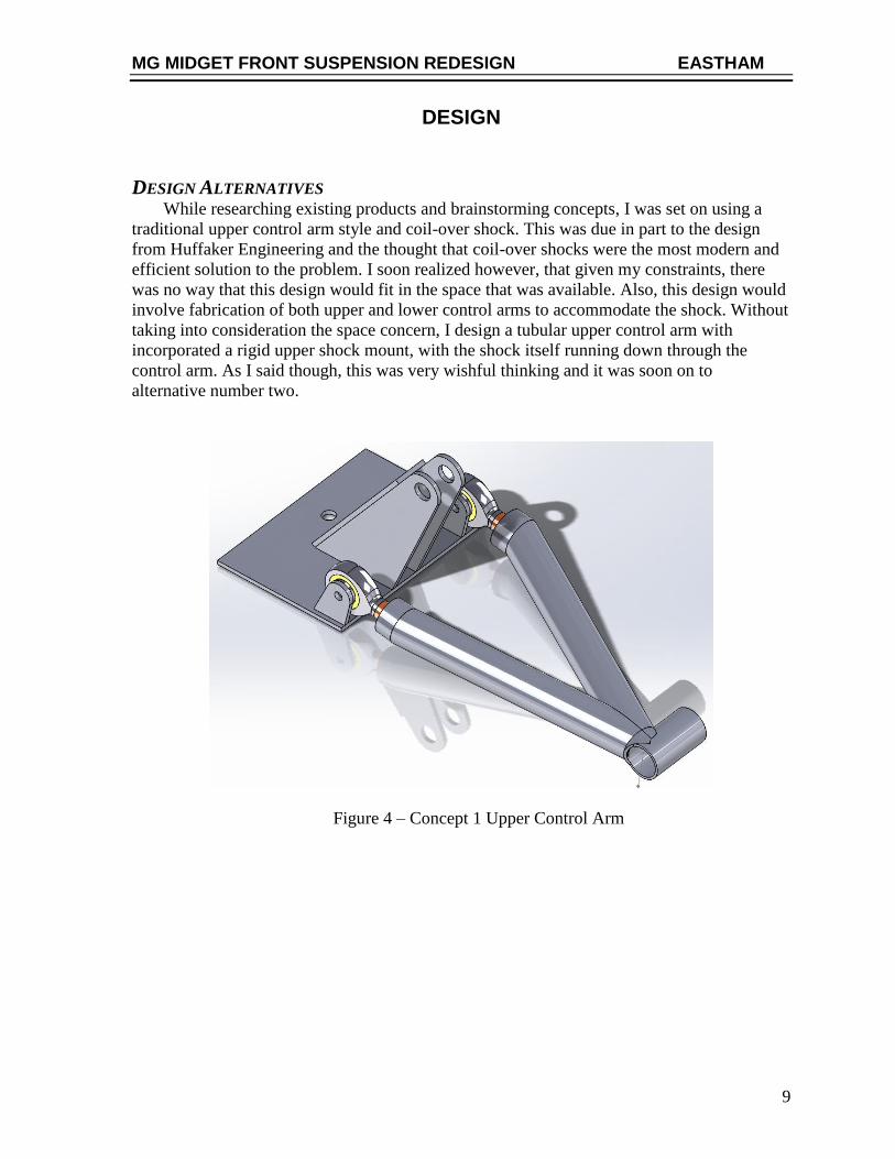
DESIGN ALTERNATIVES While researching existing products and brainstorming concepts, I was set on using a
traditional upper control arm style and coil-over shock. This was due in part to the design
from Huffaker Engineering and the thought that coil-over shocks were the most modern and
efficient solution to the problem. I soon realized however, that given my constraints, there
was no way that this design would fit in the space that was available. Also, this design would
involve fabrication of both upper and lower control arms to accommodate the shock. Without
taking into consideration the space concern, I design a tubular upper control arm with
incorporated a rigid upper shock mount, with the shock itself running down through the
control arm. As I said though, this was very wishful thinking and it was soon on to
alternative number two.
Figure 4 – Concept 1 Upper Control Arm

MG MIDGET FRONT SUSPENSION REDESIGN EASTHAM
10
Figure 5 – Concept 1 Upper Control Arm and Shock

MG MIDGET FRONT SUSPENSION REDESIGN EASTHAM
11
After some more brainstorming, a new shock location was decided on, which fit the
space criteria very well. This is a design which is utilized on several race cars and high end
production cars, yet never seen on an MG Midget. I would soon find out why that was the
case. While the new location fit in the given space and had a unique look. It was soon
realized through simulations that the shock would see little to no travel in this configuration.
Figure 6 – Concept 2 – Suspension Unloaded
Figure 7 – Concept 2 – Suspension Fully Loaded
When simulating the motion of the upper control arm in Solidworks, it was discovered
that every vertical inch of wheel travel translated to about an eighth of an inch of shock
travel. So, for five inches of wheel travel, the shock would only compress about one inch.
This amount of compression in a shock is not practical for a road car and would result in a
ride that felt undamped. After more research, I found that this was because of the angle
similarity between the upper control arm and shock. The cars that use this design have a
linkage coming from the lower control arm to actuate the shock as opposed to the upper
control arm like I had designed. This was not an option for me due to the space constraints,
though.

MG MIDGET FRONT SUSPENSION REDESIGN EASTHAM
12
With the knowledge of shock positioning in hand, a new concept was thought up which
would give the shock maximum travel. This design was more of an affirmation that the shock
travel was possible while sticll mounting it to the upper control arm. However, this meant
using a rather large and unsightly upper mount as anything in that are on the vehicle was not
structural. This design, along with the last allowed the use of the stock lower control arm and
coil spring while still going with the idea of a traditional upper “A-Arm”. Due to the postion
of the shock, it sees nearly the same amount of compression as the wheel sees in vertical
travel, solving that problem. The next iteration would need to utilize this type of shock
postioning while coming up with a better solution for the top mount.
Figure 8 – Concept 3

MG MIDGET FRONT SUSPENSION REDESIGN EASTHAM
13
The bottom shock mount was positioned as close to end of the upper control arm as
possible to utilize as much wheel travel as possible. To help alleviate some stress on the tall
upper mount, two were used, one on either side of the shock eyelet. The upper control arm
was rotated 180°, biasing it towards the front of the car to clear an existing body panel.
Figure 9 – Concept 3

MG MIDGET FRONT SUSPENSION REDESIGN EASTHAM
14
I decided to revisit the lateral positioning of the shock, as that optimizes the given
space and would without a doubt be the preferred orientation. I moved the mount farther in
from the end of the upper control arm which gave the shock a more vertical position, the
inside mount was still to be determined. Once again this proved fruitless and was perhaps a
waste of time. The solid mount would have ended up well inside of the engine bay and would
likely have seen many interferences. Aside from that, the mount would have ended up
looking like that seen in the previous concept, which I was trying to avoid. However, given
how well the shock itself would fit in the car, it was hard to let go.
Figure 10 – Concept 4

MG MIDGET FRONT SUSPENSION REDESIGN EASTHAM
15
Due to space contraints within the wheel well and the inabilty to position the shock
transversly, it was decided to move the shock inside the engine bay for the next concept. The
helped to alleviate the space concerns as there was open space directly inside of each fender
that could be used. As is rather evident, this concpet uses several linkages to transmit the
with motion to the shock. Using the same mount point on the upper control arm, a linkage
was created to transmit this motion. With an offest pivot point, a 1:1 ration was achieved
between wheel and shock travel. This technique of using long linkages was not ideal and
would likely make for a system with.
Figure 11 – Concept 5

MG MIDGET FRONT SUSPENSION REDESIGN EASTHAM
16
DESIGN SELECTION
A time came where it seemed as if no design would be feasible without the use of some
kind of linkage. After reviewing all of the previous concepts, as well as existing products
already on the market and idea came about. This new design uses a feature of the kit offered
by Frontline Developments. To revisit that design, the shock is mounted directly to the lower
control arm which gives the shock its motion. An alternative I saw to that design was to
replace the shock with a solid link, while carrying on the idea to mount the shock inboard of
the suspension. To connect the components and transmit the motion would require the use of
a linkage.
Figure 12 – Final Concept Design – Side View

MG MIDGET FRONT SUSPENSION REDESIGN EASTHAM
17
Figure 13 – Final Concept Design – Rear View
There are two very obvious design changes in this concept as compared to the previous
concepts. The first is the position of the shock. To better utilize the available space within the
engine bay, the shock is running front to back with the bottom mount much lower than the
top. Aside from alleviating space issues, this also allows the use of a more standard length
shock which means more option in shock selection.
The second and perhaps most significant change is the use of a single upper control arm
as opposed to the traditional “A-Arm” design which I have referenced. The original design
uses just one arm in the same position as the one seen in the photos. The offset of the arm is
to resist the torque of the wheel under acceleration and braking. The new arm to be used
comes will be adjustable through the use of a heim joint on the outside and features billet
aluminum construction. This control arm is used on Honda Civics and S200s. It features the
same eye to eye length and as preciously said will feature the same offset as the existing arm.

MG MIDGET FRONT SUSPENSION REDESIGN EASTHAM
18
Figure 14 – Final Concept Design – Front View

MG MIDGET FRONT SUSPENSION REDESIGN EASTHAM
19
LOADING CONDITIONS
In order to figure out the loading condition on the suspension, I first needed to find out
the center of gravity, roll center, roll rates and weight transfer. This would allow me to
determine the maximum loading conditions and implement a factor of safety.
Total Vehicle Weight (W): 1590 lb. Wheelbase (l): 80 in.
Front Weight (WF): 843 lb. Front Track Width (TF): 46.3 in.
Rear Weight (WR): 747 lb. Rear Track Width (TR): 44.8 in.
-
-
-
- 𝑊𝐹 = 𝑊1 + 𝑊2
843 𝑙𝑏 = 421.5 𝑙𝑏 + 421.5 𝑙𝑏
- 𝑊𝑅 = 𝑊3 + 𝑊4
747 𝑙𝑏 = 373.5 𝑙𝑏 + 373.5 𝑙𝑏
Y’
W2 W4
W3 W1
TF TR
CG
a b
l
Y’

MG MIDGET FRONT SUSPENSION REDESIGN EASTHAM
20
Front/Back Center of Gravity Location:
- 𝑏 =𝑊𝐹∗𝑙
𝑊
𝑏 =(843𝑙 𝑙𝑏)∗(80 𝑖𝑛)
(1590 𝑙𝑏)
𝑏 = 𝟒𝟐. 𝟒 𝒊𝒏
- 𝑎 = 𝑙 − 𝑏
𝑎 = (80 𝑖𝑛) − (42.4 𝑖𝑛)
𝑎 = 𝟑𝟕. 𝟔 𝒊𝒏
- 𝑑 =𝑇𝐹−𝑇𝑅
2
- 𝑑 =(46.3𝑖𝑛 − 44.8𝑖𝑛)
2
- 𝑑 = 𝟎. 𝟕𝟓𝒊𝒏
Lateral Center of Gravity Location:
- 𝑌′ =𝑊2
𝑊(𝑇𝐹 − 𝑑) −
𝑊1
𝑊(𝑑) +
𝑊4∗𝑇𝑅
𝑊
𝑌′ =(421.5𝑙𝑏)
(1590𝑙𝑏)(46.3𝑖𝑛 − 0.75𝑖𝑛) −
(421.5𝑙𝑏)
(1590𝑙𝑏)(0.75𝑖𝑛) +
(373.5𝑙𝑏) ∗ (44.8𝑖𝑛)
(1590𝑙𝑏)
𝑌′ = 𝟐𝟐. 𝟒𝒊𝒏
Weight Transfer:
- 𝑇𝑊 = 𝑊∗𝐶𝐺𝐻∗𝐺
𝑇𝐹
𝑇𝑊 = (1590 𝑙𝑏)∗(6 𝑖𝑛)∗(0.83𝑔)
(46.3 𝑖𝑛)
𝑇𝑊 = 𝟏𝟕𝟏 𝒍𝒃

MG MIDGET FRONT SUSPENSION REDESIGN EASTHAM
21
Front Wheel Load:
- 𝐹𝑊𝐿 = 𝑊1 + 𝑇𝑊
𝐹𝑊𝐿 = (421.5 𝑙𝑏) + (171𝑙𝑏)
𝐹𝑊𝐿 = 𝟓𝟗𝟐. 𝟓 𝒍𝒃
Factory of Safety: 3
Adjusted Wheel Load:
= 𝐹𝑊𝐿 ∗ 𝐹𝑂𝑆
= (592.5 𝑙𝑏) ∗ 2
= 𝟏𝟕𝟕𝟕. 𝟓 𝒍𝒃
Stress on Primary Linkage:
𝑇 = 𝑓 ∗ 𝑑
𝑇 = (1777.5 𝑙𝑏) ∗ (3𝑖𝑛)
𝑇 = 𝟓𝟑𝟑𝟐. 𝟓 𝒊𝒏 ∗ 𝒍𝒃
𝜏 = 𝑇
𝐼
Moment of Inertia: 𝐼 = 𝜋∗𝑟4
4
𝜏 = 5332.5 𝑖𝑛 ∗ 𝑙𝑏
𝜋 ∗ (0.5)4
4
𝜏 = 𝟏𝟎𝟖, 𝟔𝟑𝟑 𝒑𝒔𝒊

MG MIDGET FRONT SUSPENSION REDESIGN EASTHAM
22
DESIGN ANALYSIS
The primary link of concern in this design is the “L-Linkage” which transmits the
vertical motion of the wheel to compression of the shock. The linkgage sees torque as it
rotates in order to trasnmit that motion. In calculations I found that it worst case it will
experience around 108,000 psi of torsional stress. To simulate this stress, I used Solidworks
FEA function to apply the torque. One difference between this piece and the piece to be
manufactured is the material. The closest material I could find in the simulation was 4340
CD which has a lower yield stress than the material that I intend to use. Also, in this analysis
the furthest end was fixed in order to see the stress in the longest, horizont piece. The actual
linkgae however will nto be fixed at all but will instead be free to rotate in the bushing.
Because of this, I anticipate the stresses in the link will actually be lower than shown.
Figure 15 – FEA of “L-Linkage”

MG MIDGET FRONT SUSPENSION REDESIGN EASTHAM
23
COMPONENT SELECTION
When selecting material for the L-Linkage, options were limited due to the necessary
yield strength required. Through calculations I found that the material needs a yield strength
of at least 110,000 psi. When referencing the textbook Machine Elements in Mechanical
Design I found that 4140 OQT1000 has a yield strength of 152,000 psi, well above our
needed strength. The primary mounting hardware will all be made from ASTM A 36
structural steel. These pieces will not see high stress and the material has good weldabilty
which will help in assembly. The bushing block will be manufactured from a block of 1018
CD due to its properties which promote ease of machining.

MG MIDGET FRONT SUSPENSION REDESIGN EASTHAM
24
FABRICATION AND ASSEMBLY
The first and perhaps most important step of the fabrication process was to mock up each
piece in its final location. Each new part was test fit several times to eliminate any
unforeseen interferences or other problems upon final assembly. Even with lots of prior
planning, it came down to fitting each part on assembly and finessing several pieces to ensure
they fit just right.
I was fortunate enough to have many of the mounting and bracket pieces laser cut which
saved an immense of amount of time. Once I received the blank pieces, I first measured and
drilled all the mounting holes using a drill press. I wanted to start with the primary mounts
like the lower spring pan brackets, main control arm and linkage mount.
Figure 16 – Lower Spring Pan Mount

MG MIDGET FRONT SUSPENSION REDESIGN EASTHAM
25
Figure 17 – Control Arm and Linkage Mount
Figure 16 shows the completed lower spring pan bracket. The mounting holes are
mirrored on either side, which allowed them to be drilled simultaneously. To ensure that the
½” rod was parallel with the front of the car, holes were drilled in the mounts on a slight
angle and then filed until the rod fit securely. The rod was cut to length and threaded prior to
being welded to the mounts. Welding of the rod to the mounts was done on the car to ensure
that everything was in the right location. I had considered building a jig but decided that
using the actual piece that it would eventually attach to was the better way to do it. The rod
was welded at each joint and then removed. The washer shown on the end of the rod was
welded on last and is there to locate the heim joint.
Figure 17 shows the main plate which would eventually have a bushing block and
control arm mounts attached. A template of the hole locations was made from paperboard
and transferred to the part. The hole locations vary slightly on the driver and passenger sides,
otherwise I would have had the holes cut on the laser machine. Some trimming of the edges
and corners was necessary to make sure the plate fit flush to the car’s frame.

MG MIDGET FRONT SUSPENSION REDESIGN EASTHAM
26
In order to ensure that the suspension geometry remained the same, the mount point of
the control arm had to be in exactly the same location. Measurements of the existing arms
center point were taken in every axis and transferred to the new plate. I was able to determine
several things before welding the control arm ears. I found the height of the pivot point, the
distance in from each edge and the spacing between ears. Some things that were taken into
account were the bushing thicknesses to find the space between the mount.
Once the locations were found, lines were scored along the edges to ensure no
movement during welding. A magnet was used to hold the ears in place and they were each
welded to the main plate.
Figure 18 – Control Arm Mounts being welded

MG MIDGET FRONT SUSPENSION REDESIGN EASTHAM
27
Given the time constraints and number of other pieces needed fabricated, I had a local
machine shop help with manufacturing the bushing block. Drawings of the block, which can
be seen in the appendix, were send to the machine shop to work off of. I would have
preferred to do the machine myself to save some money, however it was necessary to farm
this part out. It is not a complex piece, but it is crucial to the operation of the design. Figure
19 shows that bushing block attached in its final location on the main plate.
Figure 19 – Completed Main Mount Plate
Figure 19 shows just how tight the clearance between the bushing block and the control arm
mounts was.

MG MIDGET FRONT SUSPENSION REDESIGN EASTHAM
28
Figure 20 – Front Shock Mount
Figure 20 shows the original design of the front shock mount. The idea was to mount the
shock to a hole that would be drilled inside of the radius at the top. After mocking up the
actual shock location it was pretty clear that having the mount that high up would not provide
enough shock travel. To compensate, the mounting hole was drilled much lower and the
excess material was cut off to reduce weight.

MG MIDGET FRONT SUSPENSION REDESIGN EASTHAM
29
Figure 21 – Linkage Shoulder Machining
The shoulder which rides inside of the busing block was machined on a lathe as shown
in Figure 21. It was crucial to get the lcoation of the machined shoulder correct, otherwise the
allignment of the linkage would be off.

MG MIDGET FRONT SUSPENSION REDESIGN EASTHAM
30
Figure 22 shows a mock-up of the main linkage. A “fishmouth” was machined into each
end of the horizontal piece so that the remaining two pieces would fit flush and to provide a
joint to weld. This figure also shows a hole that was drilled and tapped in the end of each of
the two pieces. This hole of the top side was for attaching the shock mount, and on the back
side for attaching the pushrod. The center drilling of the holes was also done on the lathe to
ensure that the hole was perfectly centered in the piece.
Figure 22 – Linkage Mock-Up

MG MIDGET FRONT SUSPENSION REDESIGN EASTHAM
31
Figure 23 – Completed Driver Side Parts
Figure 23 shows all of the parts ready for assembly on the driver’s side of the car. Part A
is the main linkage which is responsible for transmitting the wheel travel to the shock. Part B
is the lower spring pan bracket which provides a mounting point for the pushrod. Item C is
the main plate which has the bushing block and control arm mounts attached. Item D is the
front shock mount after being modified from the original design. Part E is the pushrod which
mounts to the lower spring pan bracket and provides the vertical motion to the main linkage.
Parts F are the mounts which attach to the tapped holes on each end of the main linkage. The
wider bracket is the top shock mount while the narrower bracket attaches to the heim join on
Item E. Finally, part G is the control arm which was drilled for a heim joint to provide the
camber adjustability.
The figure also shows the final finish that was applied to each part. The parts were all
powder coated to ensure a long life for the parts. Some advantages of powder coating is that
no cure time is necessary so the parts can be installed almost immediately after being coated.
Also it is a much more wear resistant finish when compared to paint.
A B
C
D
E
G
F
MG MIDGET FRONT SUSPENSION REDESIGN EASTHAM
32
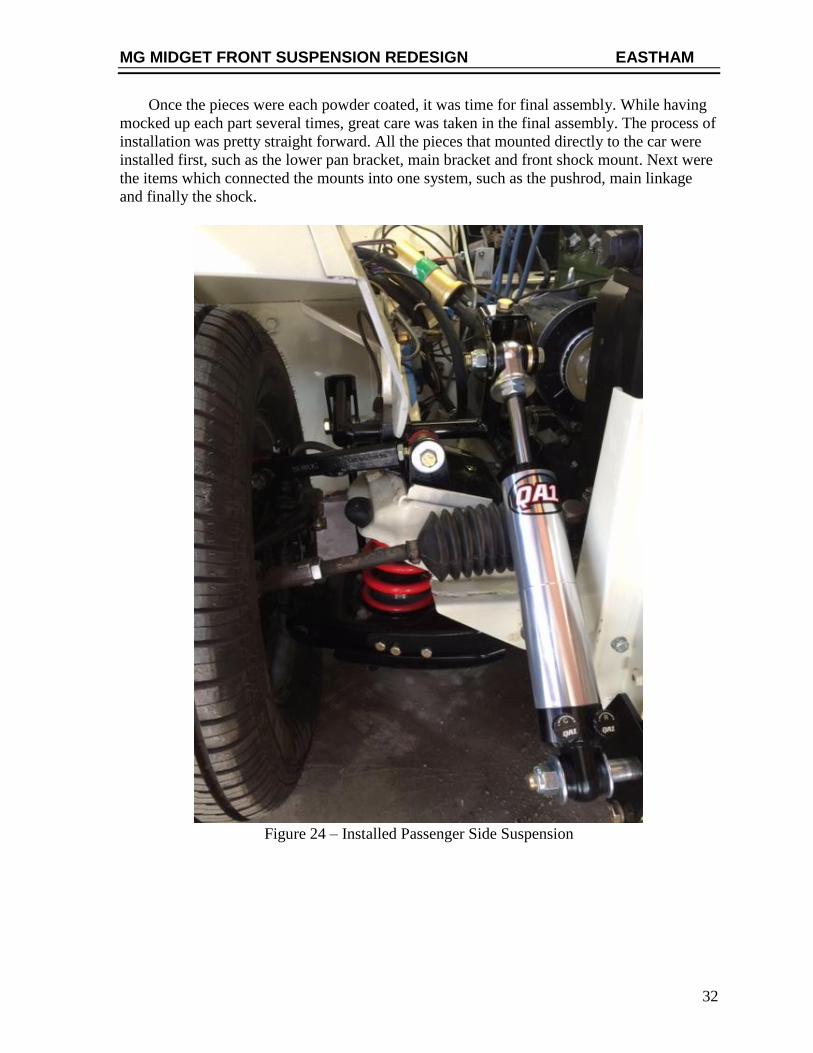
Once the pieces were each powder coated, it was time for final assembly. While having
mocked up each part several times, great care was taken in the final assembly. The process of
installation was pretty straight forward. All the pieces that mounted directly to the car were
installed first, such as the lower pan bracket, main bracket and front shock mount. Next were
the items which connected the mounts into one system, such as the pushrod, main linkage
and finally the shock.
Figure 24 – Installed Passenger Side Suspension

MG MIDGET FRONT SUSPENSION REDESIGN EASTHAM
33
Figure 25 – Detail of the Passenger Side Shock

MG MIDGET FRONT SUSPENSION REDESIGN EASTHAM
34
Figure 26 – New suspension after final assembly

MG MIDGET FRONT SUSPENSION REDESIGN EASTHAM
35
TESTING
It was quite a rewarding and nerve-wracking experience lowering the car off of the jack
for the first time. This was the moment of reckoning and would be the first indicator of
whether the project was a success or not. Sure enough, as the weight was lowered onto the
new suspension, the shock compressed as expected.
As far as the actual driving performance of the car with the new suspension, I was not
able to gather data for some of the items identified in the proof of design. However, the main
goal of the project was achieved because of the range of adjustability. The idea was to take a
non-adjustable suspension and make it adjustable and that was done. The user now has nearly
infinite adjustability of the shock damping where before there was none. Also, there is a wide
range of camber adjustments which can be made with the control arm, where before there
was also none. Aside from those two critical adjustments, preload of the shock can also be
adjusted by changing the length of the vertical pushrod. All in all it took about an hour to
install both sides of the suspension. This was done with one person while taking my time to
ensure everything still fit correctly. Having done it several times now, and with another set of
hands, I am confident both sides can be installed in under one hour. An adjustment to the
camber was necessary when the car was dropped off the jacks. This required the removal of
one bolt, loosening the heim joint and reinstalling. The camber adjustment for both sides can
be completed in under ten minutes.
While no tests were done to measure the road holding capabilities of the new versus the
old suspension, the car was driven to ensure cycling of the shock. The test was done on a
relatively bumpy road with the shock set on the softer side of its adjustment range. A camera
was attached to record the shock functioning as the car was driven. Reviewing the footage
showed that the suspension worked exactly as designed. With the preload at its current
setting there is plenty of stroke for both compression and rebound without a concern of
bottoming out or overextending the shock. Overall I am really pleased with how the final
product turned out and its adjustability improvement over the old design.

MG MIDGET FRONT SUSPENSION REDESIGN EASTHAM
36
PROJECT MANAGEMENT
SCHEDULE
Figure 27 – Proposed Project Schedule
TASKS Sep
29
-Oct
5O
ct 6
- 1
2
Oct
13
- 1
9
Oct
20
- 2
6
Oct
27
- N
ov
2
No
v 3
- N
ov
9
No
v 1
0 -
16
No
v 1
7 -
23
No
v 2
4 -
30
Dec
1 -
7
Dec
8 -
14
Dec
15
- 2
1
Dec
22
- 2
8
Dec
29
- J
an 4
Jan
5-
Jan
11
Jan
12
- 1
8
Jan
19
- 2
5
Jan
26
- F
eb 1
Feb
2 -
8
Feb
9 -
15
Feb
16
- 2
2
Feb
23
- M
ar 1
Mar
2 -
8
Mar
9 -
15
Mar
16
- 2
2
Mar
23
- 2
9
Mar
30
- A
pr
5
Ap
r 6
- 1
2
Ap
r 1
3-
19
Ap
r 2
0 -
26
Proof of Design Agree (advisor) 5
Concepts/Selection (advisor) 25
3D Model - (name sub-assmby) 30
Design Freeze 8
BOM 8
Order Parts 22
Mock Up 15
Design Presentation 4
Report to Advisor 22
Paint/Powdercoat 22
Final Assembly 29
Demonstration to Advisor 5
Tech Expo 3
Prsentation to Faculty 8
Finalize Report 23
Present to Advisor 16
Library PDF 23
Cooper Eastham
MG Midget Front Suspension

MG MIDGET FRONT SUSPENSION REDESIGN EASTHAM
37
Figure 28 – Actual Project Schedule
TASKS Sep
29
-Oct
5O
ct 6
- 1
2
Oct
13
- 1
9
Oct
20
- 2
6
Oct
27
- N
ov
2
No
v 3
- N
ov
9
No
v 1
0 -
16
No
v 1
7 -
23
No
v 2
4 -
30
Dec
1 -
7
Dec
8 -
14
Dec
15
- 2
1
Dec
22
- 2
8
Dec
29
- J
an 4
Jan
5-
Jan
11
Jan
12
- 1
8
Jan
19
- 2
5
Jan
26
- F
eb 1
Feb
2 -
8
Feb
9 -
15
Feb
16
- 2
2
Feb
23
- M
ar 1
Mar
2 -
8
Mar
9 -
15
Mar
16
- 2
2
Mar
23
- 2
9
Mar
30
- A
pr
5
Ap
r 6
- 1
2
Ap
r 1
3-
19
Ap
r 2
0 -
26
Ap
r 2
7 -
May
1
Proof of Design Agree (advisor) 5
Concepts/Selection (advisor) 25
3D Model - (name sub-assmby) 30
Design Freeze 8
BOM 8
Order Parts 22
Mock Up 15
Design Presentation 4
Report to Advisor 22
Paint/Powdercoat 12
Final Assembly 12
Demonstration to Advisor 5
Tech Expo 16
Prsentation to Faculty 22
Finalize Report 1
Present to Advisor 16
Library PDF 1
Cooper Eastham
MG Midget Front Suspension

MG MIDGET FRONT SUSPENSION REDESIGN EASTHAM
38
BUDGET
Component Description Vendor Qty Cost (Ea.)
Shocks QA1 Model: TD 403 Double Adjustable
Summit Racing 2 $250.00
Heim Joint Female Thread
McMaster Pt. 60685K341 McMaster Carr 2 $15.00
Misc. Hardware Nuts & Bolts Hardware Exchange $100.00
Upper Link NRG Innovations Control
Arm DME Suspension 2 $115.00
U Bracket Threaded U Bracket MSC 2 $25.00
Raw Materials
Round Bar 4140 Cold Drawn
5/8" OD x 18" Alro 1 $55.00
Round Bar 4140 Cold Drawn
1" OD x 36" Alro 1 $65.00
Sheet Steel A-36
3/16" Thick x 12" x 36" Alro 1 $60.00
Steel Block A-36
1" x 2" x 12" Long Alro 1 $40.00
Bronze Bushing Bronze
1-1/4" OD x 1" ID x 2" Long Alro 1 $50.00
Total
$1,180.00
Figure 29 – Proposed Project Budget

MG MIDGET FRONT SUSPENSION REDESIGN EASTHAM
39
Component Description Vendor Price
New Shocks QA1 TD504 Summit Racing 518.75
Old Shocks Lever Arm Ebay 30
Heim Joints Male/Female Pegasus Racing 119
Bushings Prothane Amazon 17.52
Arm Machining Drilled and Tapped TLC Fabrication 20
Shock Mounts For shock & heim joint Rusty's Offroad Supply 60
Bushing Blocks Machining API Machining 300
Linkage Raw Material Stock Car Steel 45
Total 1110.27
Figure 30 – Actual Project Budget

MG MIDGET FRONT SUSPENSION REDESIGN EASTHAM
40
REFERENCES
1. Sprite and Midget History of Development and Production. Spridget Mania. [Online] June
19, 2000.
http://www.spridgetmania.com/Sprite_and_Midget_History_of_Development_and_Productio
n_604.
2. Tube Shock Conversion Kit Front Sprite & Midget. Spridget Mania. [Online] 2014.
http://spridgetmania.com/part/1600-FLD/Tube-Shock-Conversion-Kit-Front-Sprite--Midget.
3. Midget: Front Suspension Kit. Frontline Developments. [Online] 2014.
http://www.frontlinedevelopments.com/products/midget/frontsuspensionkit.shtml.
4. Caldwell, Peter. World Wide Auto Parts. October 7, 2014.
41
APPENDIX A - RESEARCH
Interview with Peter Caldwell
Owner of World Wide Auto Parts
2517 Seiferth Rd.
MADISON, WI 53716, Phone: (800)362-1025
Peter Caldwell owns a business which rebuilds lever shocks. I spoke with him regarding
some of the history of lever shocks and why they were used on the Sprites and Midgets. I
also asked him what the main deficiencies are and how those can be fixed, as well as ways to
adjust the shocks.
Interview with MG expert: David Anton
Owner of APT – Advanced Performance Technology
595 Iowa Avenue, Suite C
Riverside CA 92507, Phone: (951)686-0260
I talked with Mr. David Anton regarding the history of the car on both the street and the
racetrack. APT deals primarily with engine components however he has a general knowledge
of each subassembly on the car.
Interview with Huffaker Engineering
Huffaker Engineering
29601 Arnold Drive
Sonoma, CA 95476
Phone (707) 935-0533

42
Tube Shock Conversion Kit Front Sprite & Midget
Replace the stock shock with a stronger, fabricated upper arm.
With the addition of a lower support bracket that also reinforces
the lower arm, your car will now accept conventional, tubular
shocks.
The upper A Arm is
rather bulky.
The upper A-Arm in my
design would utilize
round tubing to save
weight.
$1395 USD
Huffaker Front Suspension
The Huffaker front suspension uses tubular upper and lower A-
Arms and a centrally located coil over shock. The use of this
design also requires modification of the existing steering rack as
well as body panels. This design allows for the adjustability of the
wheel camber.
This design is no longer available.
This kit requires
extensive replacing or re
fabrication of parts.
Don’t have ability to go
back to original for any
reason.
Difficult to replace
shock with central
mounting.
??? USD
http://www.spridgetmania
.com/part/1600-
FLD/Tube-Shock-
Conversion-Kit-Front-
Sprite--Midget
September 15, 2014

43
Frontline Suspension
The original damper unit is replaced with a new upper wishbone
and enables the vertical positioning of an adjustable telescopic
damper. Built into the top mount is a negative camber angle of
one degree. This tightens up the front end reducing understeer to
produce a more rapid cornering response and superior road
holding in all conditions.
Another bulky design.
Mimics other designs
already on the market.
No adjustability
Allows for easy shock
replacement
$1400 USD
http://www.frontlinedev
elopments.com/products
/midget/frontsuspension
kit.shtml
September 15, 2014

44
APPENDIX B – PRODUCT OBJECTIVES
1. Provide adjustability 25%
a. Use of heim joints to adjust wheel camber
b. Factory tie-rods retained to adjust toe in
c. Modern shocks to allow adjustability
d. Ability to fit several years
2. Fit modern shock absorbers 15%
a. Gas filled
b. Adjustable in both compression and rebound
3. Separate suspension components 10%
a. Upper control arm and shock are individual components
4. Easy installation 10%
a. Double check measurements
b. Ensure tolerances are correct
c. Build jig to keep assembly consistent
5. Safety 10%
a. Ensure welds are strong
b. Use some type of cold rolled tubing
c. Use proper grade hardware
6. Cost 5%
a. Less than $1500
7. Predictable
function 5%
a. Ensure that wheel travels in same path
b. Allow use of factory mounts
c. Retain stock suspension geometry
8. Stable while driving 10%
a. No speed wobble
b. Good bump absorption
c. Smooth street ride
d. Ability to stiffen for track use
9. Durability 10%
a. Design factor consistent with weight of car
b. Powder coat components

45
APPENDIX C – SCHEDULE
TASKS Sep
29
-Oct
5O
ct 6
- 1
2
Oct
13
- 1
9
Oct
20
- 2
6
Oct
27
- N
ov
2
No
v 3
- N
ov
9
No
v 1
0 -
16
No
v 1
7 -
23
No
v 2
4 -
30
Dec
1 -
7
Dec
8 -
14
Dec
15
- 2
1
Dec
22
- 2
8
Dec
29
- J
an 4
Jan
5-
Jan
11
Jan
12
- 1
8
Jan
19
- 2
5
Jan
26
- F
eb 1
Feb
2 -
8
Feb
9 -
15
Feb
16
- 2
2
Feb
23
- M
ar 1
Mar
2 -
8
Mar
9 -
15
Mar
16
- 2
2
Mar
23
- 2
9
Mar
30
- A
pr
5
Ap
r 6
- 1
2
Ap
r 1
3-
19
Ap
r 2
0 -
26
Proof of Design Agree (advisor) 5
Concepts/Selection (advisor) 25
3D Model - (name sub-assmby) 30
Design Freeze 8
BOM 8
Order Parts 22
Mock Up 15
Design Presentation 4
Report to Advisor 22
Paint/Powdercoat 22
Final Assembly 29
Demonstration to Advisor 5
Tech Expo 3
Prsentation to Faculty 8
Finalize Report 23
Present to Advisor 16
Library PDF 23
Cooper Eastham
MG Midget Front Suspension

46
APPENDIX D – BUDGET
Component Description Vendor Qty Cost (Ea.)
Shocks QA1 Model: TD 403 Double Adjustable
Summit Racing 2 $250.00
Heim Joint Female Thread
McMaster Pt. 60685K341 McMaster Carr 2 $15.00
Misc. Hardware Nuts & Bolts Hardware Exchange $100.00
Upper Link NRG Innovations Control
Arm DME Suspension 2 $115.00
U Bracket Threaded U Bracket MSC 2 $25.00
Raw Materials
Round Bar 4140 Cold Drawn
5/8" OD x 18" Alro 1 $55.00
Round Bar 4140 Cold Drawn
1" OD x 36" Alro 1 $65.00
Sheet Steel A-36
3/16" Thick x 12" x 36" Alro 1 $60.00
Steel Block A-36
1" x 2" x 12" Long Alro 1 $40.00
Bronze Bushing Bronze
1-1/4" OD x 1" ID x 2" Long Alro 1 $50.00
Total
$1,180.0
0

47
APPENDIX E – DRAWINGS

48

49

50

51

52