MFL69020902 IEC G4(ECO) 150907 - LG Solar Energy€¦ · component voltage ratings, conductor...
12
Polycrystalline Solar Module LGXXXP1W-M3 Installation Instructions MFL69020902
Transcript of MFL69020902 IEC G4(ECO) 150907 - LG Solar Energy€¦ · component voltage ratings, conductor...

Polycrystalline Solar ModuleLGXXXP1W-M3
Installation Instructions
MFL69020902

Table of Contents
Revisions Table
2
1. Safety 3
2. Before & After Installation 4
3. Electrical Installation 5
4. Mechanical Installation 7
5. Product Specifications 9
6. Disclaimer of Liability / Disposal 10
7. Transporting and Storage 10
Date Version Description of change Remark
2015.01.22 1.0 (1st edition)
2015.09.04 2.0 Change Connector(MC4 Compatible MC4)

3
Safety
① ②
④③
⑤
The instructions related to the safety indicated in the following are for preventing unexpected danger or damage in advance by safely and exactly using the product.
Non-compliance of the instructions may immediately cause serious injury or death.
Non-compliance of the instructions may cause death or serious injury to the user.
Non-compliance of the instructions may cause injury or property damage to the user.
DANGER
DANGER① Do not contact with electrically active parts of the
panel, such as terminals, regardless of connection of the module. It may result in spark or lethal electric shock.
② Please don’t use the module with the broken window or the torn back side. There is a danger of electric shock.
WARNING
WARNING
① Please perform works in the dry condition and use only dry tools. Do not handle the wet panels without protection equipment. It may result in safety accident.
② Damaged module must be treated with safety protection equipment. It may result in injury.
③ Do not approach the damaged or broken module unless you are an expert. It may result in serious injury.
④ No electrical parts like cables are located after installation between laminate and mounting structure.
⑤ Do not reconnect or repair Junction Box Cable. It may occur spark or electric shock.
CAUTION
CAUTION
① ②
① ② ③
④ ⑤
⑦
⑨
⑧
⑥
Module Module
Installing structure(bent type)
Installing structure(Stralght type)
Product Deformation Occurrence of space
① Please use proper equipment, connector, wire and buttress for system configuration of the module. It may result in damage or failure of the product.
② Do not perform installation in rainy, heavily windy or snowy days. It may result in safety accident.
③ Do not make holes in the frame or glass of the module. It may decrease the strength of the frame or break the glass.
④ Do not touch the glass surface or frame of the solar module after installation of the module. It may result in injury.
⑤ Do not locate a heavy object onto the module. Do not stand on or step on the module. Do not drop or suddenly lay down the module. It may result in injury.
⑥ Do not scratch the coating surface of the frame. It may decrease the strength due to corrosion of the frame.
⑦ Do not concentrate sunlight on the module surface. It may result in damage of the product.
⑧ Do not apply a shock to the junction box of the module or pull the cable. Do not remove the labels attached to the module. It may result in damage of the product.
⑨ If the installing structure has a curved surface e.g. arch type as shown in the below picture, do not forcefully modify the module in installation when connecting it with the structure. Please install the module in the place where the structure has been completely set up because deformation of the structure may cause deformation of the product when performing installation by using a crane, etc after assembling the module to the installing structure.

4
Before & After Installation
• Wear a safety belt if working high above the ground.
• Contact with electrically active parts of the panels, such as terminals, can result in burns, sparks and lethal shock whether the panel is connected or disconnected.
• Even partial shadowing can substantially reduce panel and system output.
• Care must be taken to avoid low tilt angles which may cause dirt to buildup on the glass against the frame edge.
• Dirt build-up on the surface of the panel can cause active solar cells to be shaded and electrical performance to be impaired.
• Always keep the back surface of the panel free from any foreign objects or structural elements which could come into contact with the panel, especially when the panel is under mechanical load.
• For permission to use mounting methods not described in the Mounting Guide please consult LG Solar. Failure to do so will void the warranty and panel certification.
After Installation• Plug the connector in tightly and ensure that the
wiring properly works.• It is advisable to conduct periodic inspection of the
panels for damage to front glass, back sheet, frame, junction box, or external electrical connections.
• Check electrical connections for loose connections and corrosion.
• PV panels can operate effectively without ever being washed, although removal of dirt from the front glass can increase output.
• Water, ethanol or a conventional glass cleanser with a micro-fiber cloth can be used for regular washing or rinsing of the front glass to remove dust, dirt or other deposits.
• No aggressive and abrasive cleansers or chemicals such as alkali chemicals including ammonia based solution should ever be used on the treated front glass.
• Always wear rubber gloves for electrical insulation while maintaining, washing or cleaning panels.
• Deposits of foreign material on the frame surface can be cleaned using a wet sponge or cloth and dried in air or by using a clean chamois.
• Perform the wiring work by connecting the connector and wires to the stand away from the roof or ground.
Before InstallationPlease carefully read this manual before installation.• Solar module installation should be performed by
an authorized installer for the safety and maintenance of the system.
• All installation instructions should be clearly understood before attempting installation.
• Do not twist, pull, or scratch the cable attached to the solar module.
• Do not touch the solar module with bare hands. It may result in a burn or injury.
• Do not drop the solar module and cause an excessive load on solar module.
• Do not disassemble the solar module.• After installation or repair, check whether solar
module operates properly or not.• In case the currently used solar module or the
parts applied to the solar module have been replaced, check whether the changed solar module is properly operated or not. The newly replaced solar module and its parts must be the same solar module(module name) and parts with the current solar module.
• Please contact the local office to confirm the regulations and to obtain permission.
• Do not let anyone approach the solar module who has little knowledge of solar modules or on the measures to take when solar modules are damaged in order to avoid the risk of injury or electrical shock.
• Do not locate the solar module horizontally, as this may cause dirt or white efflorescence (glass deformation)
• Panels produce voltage even when not connected to an electrical circuit or load.
• Panels are intended for outdoors, land based applications only. Panels are not intended for use indoor use or application on moving vehicles of any kind.
• Reflection from external environments such as snow, water or other surfaces can increase the power generated by the panel.
• Industry standard rated specifications are made at conditions of 1000W/m2 irradiance and 25°C (77°F) solar cell temperature. Colder temperatures can substantially increase voltage and power.
• Keep the solar module and system away from children when installing.
• Keep the module packed in the carton until the time of installation.
• Make sure flammable gases are not generated near the installation site.
• Do not work alone. Please work as part of a team of two or more people.

--
Parallel connection for more current
5
Electrical Installation
Parallel Connection• The solar modules may be combined in parallel to
produce the desired current output.• When modules are combined in parallel, the total
current is equal to the sum of currents from each module.
• The voltage of each module connected in parallel should be same.
• When connecting plural strings of modules in parallel every series string or solar module must be fused prior to combining with other strings. By pass diodes are factory installed in the solar modules.
• Please refer to the applicable regional and local codes for additional fusing requirements and limitations on the maximum number of solar modules in parallel.
• Maximum parallel strings without proper measures, e.g. fuse 15A and/or blocking diode : 1 string Parallel configuration is not limited if proper measures are taken to block the reverse current flow, e.g. fuses for the protection of the module and cables from over-current and/or blocking diodes for prevention of unbalanced string voltage.
• A multiplying factor is required for increased output of the PV modules. Under normal conditions, a PV module is likely to experience conditions that produce more current and/or voltage than reported at standard test conditions. Accordingly, the values of Isc and Voc marked on this PV module should be multiplied by a factor of 125% when determining component voltage ratings, conductor ampacities, fuse sizes, and size of controls to the PV output.
• Depending on national directives additional safety factors might be applicable for overcurrent protection.
Caution• Avoid all electrical hazards when installing, wiring,
operating and maintaining a panel.• Do not use panels of different electrical or physical
configurations in the same system.• Match the polarities of cables and terminals when
making the connections; failure to do so may result in damage to the panel.
• When reverse currents can exceed the value marked on the name plate, a properly rated and certified over-current device (fuse or circuit breaker) must be connected in series with each panel or string of panels.
• The rating of the over-current device shall not exceed the maximum series fuse rating marked on the name plate.
• The panel contains factory installed bypass diodes located inside the junction box.
• When installing the system, it is recommended to install the lightning rod to protect the system.
• The junction box should not be opened. Opening the junction box may void the warranty.
• Panels with a suspected electrical problem should be returned to LG Electronics for inspection and possible repair or replacement as per the warranty conditions provided by LG Electronics.
Electrical Connections• Modules may be connected in series and/or
parallel to achieve the desired electrical output as long as certain requirements are met.
• Please use only the same type of modules in a combined source circuit.
• Do not disconnect the module under load. Shock hazard can occur near the solar modules connection means.
Series Connection• The solar modules may be wired in series to
produce the desired voltage output. • The current of each module connected in series
should be same. • The maximum number of series connected
modules can be determined by basis on max. system voltage, the 125% safety factor, and the module Voc which can be checked in “Product Specifications” in this document.
• Do not exceed 80% of maximum system voltage.• The maximum solar module configuration can be
found in “Product Specifications”.
Series connection for more voltage

6
General Wiring• LG Electronics recommends that all wiring be
double insulated with a minimum rating of 90°C (194°F).
• All wiring should use a flexible copper (Cu) conductor.
• The minimum size should be determined by the applicable codes.
• We recommend a size not smaller than 4mm2.
Earth Grounding• The solar modules from LG Electronics meet the
conditions of safety class II. Therefore grounding is not mandatory. However grounding is recommended. Also equipotential bonding must be realized. The national directives must be respected.
• Specific information on the solar module dimensions and location of grounding holes is provided in ‘Product Specifications’.
• One M4 stainless steel bolt, one nut, one spring washer, two flat washers, one cup washer, one star washer and 12 AWG Cu wires are recommended per solar module.
• There is an earth hole in the center of the module frame. Using this hole, an earth conductor and the solar module frame may be recommended to connected and earthed as the below drawing.
• To prevent electric shock and fire, a protective ground must be done on the frames of solar modules and arrays although the solar modules from LG Electronics meet the conditions of safety class II. The national directives must be respected.
Module frame
Bolt
Flat washer
Star washer
Cup washer
Flat washer
Spring washer
Nut
Grounding wire

7
Mechanical Installation
Module Mounting• The LG Electronics’ (LGE) Limited Warranty for
solar modules is contingent upon modules being mounted in accordance with the requirements described in this section.
• The solar modules are in Application Class A and have the Safety Class II. Therefore they can be operated in systems with 120 V DC and higher. General access is not restricted.
Site ConsiderationLGE solar modules should be mounted in a location that meets the following requirements.Operating Temperature• Maximum Operating Temperature: +90°C (194°F)• Minimum Operating Temperature: -40°C (-40°F)Design Strength• Front loads : 3600 Pascal• Rear loads : 2400 PascalExcluded Operating Environments• The solar modules from LG Electronics can be
operated in a location where they could come in contact with salt water or ammonia, if they have been tested successfully for these operating conditions. Please see related certificates. Please get a release from LG Electronics for increased conditions.
Mounting MethodsGeneral Information• Select the appropriate orientation to maximize
sunlight exposure. • In order to prevent water from entering the junction
box, which could present a safety hazard, module should not be mounted such that the front/top glass faces downward.
• Clearance between the solar module frames and structures such as roofs or ground is required to prevent wiring damage and to allow air to circulate behind the solar module. The recommended standoff height is a minimum of 100mm.
• When installed on a roof, the solar module must be mounted over a fire-resistant roof covering rated for the application. The fire resistance of the solar module from LG Electronics is class C after ANSI/UL790.
• The solar module is only IEC listed for use when its factory frame is fully intact.
• Do not remove or alter the solar module frame.• Creating additional mounting holes may damage
the solar module and reduce the strength of the frame.
• A 6mm gap between module frames should be allowed to avoid tension from thermal expansion.
• The solar module may be mounted using the following methods: (*Torque:8~12Nm )
• When installing modules in heavy snow areas, special care should be taken to install the modules in a manner that provides sufficient design strength while meeting local code requirements.
Mounting by using frame bolts holes• Secure the solar module to the structure using the
factory mounting holes.• Four M6 stainless steel bolts, four nuts, four spring
washers, and eight flat washers are recommended per solar module.
• The module may be fastened to a support using both the outer and inner bolt holes of the frame.
• Each module should be securely fastened at a minimum 4 points on two opposite sides.
• Specific information on the solar module dimensions and location of mounting holes is provided in ‘Product Specifications’.
Bolt
Flat washer
Flat washer
Nut
Support
Module frame
Spring washer
• Tighten the bolt securely using this combination. Place spring washer between Flat washer and Nut.
Mounting by using clip or clamps• The module may be fastened to a support using
clips or clamps on both the long edge and the short edge of the modules.
• Specific information on location of clipping is provided in ‘Mechanical Installation Scene’. (Refer to next page)
More than 40mm
More than 10mm
More than 10mm

8
LGXXXP1W-M3
Mou
ntin
g Ty
peC
lam
ping
Typ
e(L
ong
Sid
e)C
lam
ping
Typ
e(S
hort
Sid
e)
150mm 150mm
Use four mounting holes on two opposite sides.
Use four clamps on the long frame.
Use four clamps on the short frame and
two clamps at the center of long frame.
Clamping Range(230mm)
Clamping Range:From module Edge
to 270mm
Clamping Range:From module Edge
to 120mm
Center ± 100mm
Center ± 100mm
Use four clamps on the Short frame.
This method is not tested by IEC/UL.
This installation is allowed in the following cases: 1. Slope roof: If module is installed parallel to the rooftop.2. Flat roof: If installed with an additional stand such as wind
shield or deflector.
9
Product Specifications
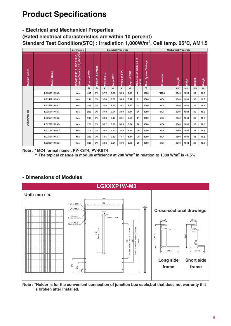
- Electrical and Mechanical Properties(Rated electrical characteristics are within 10 percent)Standard Test Condition(STC) : Irradiation 1,000W/m2, Cell temp. 25°C, AM1.5
Note : * MC4 formal name : PV-KST4, PV-KBT4 ** The typical change in module efficiency at 200 W/m2 in relation to 1000 W/m2 is -4.5%
seitreporP lacinahceMseitreporP lacirtcelEsetacifitreC
1
Mod
ule
Serie
s
Mod
el N
ame
IEC
6121
5 Ed
.2, I
EC 6
1730
,Sa
fety
Cla
ss II
, CE,
ISO
900
Pmax
at S
TC
Pow
er T
oler
ance
Voc
at S
TC
Isc
at S
TC
Vmpp
at S
TC
Impp
at S
TC
Max
. No.
of m
odul
es in
serie
s
Max
. Sys
tem
Vol
tage
Con
nect
or
Leng
th
Wid
th
Hei
ght
Wei
ght
W % V A V A V mm mm mm kgg
LGXX
XP1W
-M3
LG245P1W-M3 Yes 245 3% 37.2 8.68 30.3 8.11 21 1000 *MC4 1640 1000 35 16.8
LG250P1W-M3 Yes 250 3% 37.4 8.80 30.5 8.22 21 1000 MC4 1640 1000 35 16.8
LG255P1W-M3 Yes 255 3% 37.6 8.92 30.7 8.33 21 1000 MC4 1640 1000 35 16.8
LG260P1W-M3 Yes 260 3% 37.8 9.04 30.9 8.44 21 1000 MC4 1640 1000 35 16.8
LG265P1W-M3 Yes 265 3% 38.0 9.16 31.1 8.54 21 1000 MC4 1640 1000 35 16.8
LG270P1W-M3 Yes 270 3% 38.2 9.28 31.3 8.64 20 1000 MC4 1640 1000 35 16.8L LG270P1W M3 Yes 270 3% 38.2 9.28 31.3 8.64 20 1000 MC4 1640 1000 35 16.8
LG275P1W-M3 Yes 275 3% 38.4 9.40 31.5 8.74 20 1000 MC4 1640 1000 35 16.8
LG280P1W-M3 Yes 280 3% 38.6 9.52 31.7 8.84 20 1000 MC4 1640 1000 35 16.8
LG285P1W-M3 Yes 285 3% 38.8 9.64 31.9 8.95 20 1000 MC4 1640 1000 35 16.8
- Dimensions of Modules
Note : *Holder is for the convenient connection of junction box cable,but that does not warranty if it is broken after installed.
LGXXXP1W-M3
Cross-sectional drawings
Unit: mm / in.
Long side frame
Short side frame
10
Disclaimer of Liability / Disposal
Disclaimer of Liability• Since the use of this Safety, Installation and
Operation instructions and the conditions or methods of installation, operation, use and maintenance of the panel are beyond the control of LG Electronics, LG Electronics does not assume responsibility and expressly disclaims liability for loss, damage, injury or expense arising out of or in any connected with such installation, operation, use or maintenance of the panel.
• LG Electronics assumes no responsibility for any infringement of patents or other rights of third parties that may result from use of the panel. No license is granted by implication or otherwise under any patent or patent rights..
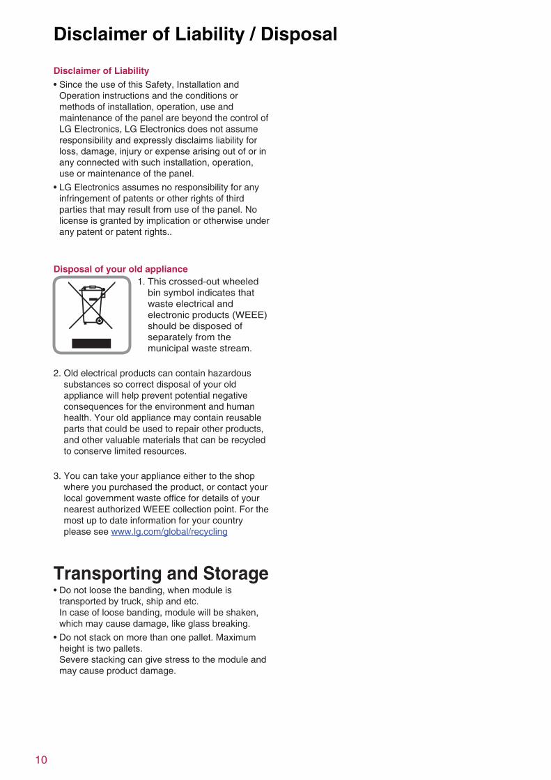
Disposal of your old appliance 1. This crossed-out wheeled
bin symbol indicates that waste electrical and electronic products (WEEE) should be disposed of separately from the municipal waste stream.
2. Old electrical products can contain hazardous substances so correct disposal of your old appliance will help prevent potential negative consequences for the environment and human health. Your old appliance may contain reusable parts that could be used to repair other products, and other valuable materials that can be recycled to conserve limited resources.
3. You can take your appliance either to the shop where you purchased the product, or contact your local government waste office for details of your nearest authorized WEEE collection point. For the most up to date information for your country please see www.lg.com/global/recycling
Transporting and Storage• Do not loose the banding, when module is
transported by truck, ship and etc. In case of loose banding, module will be shaken, which may cause damage, like glass breaking.
• Do not stack on more than one pallet. Maximum height is two pallets. Severe stacking can give stress to the module and may cause product damage.


LG Electronics Deutschland GmbHBerliner Straße 93 D-40880 Ratingen, GermanyContact: [email protected]
LG Electronics Inc. (Global HQ)LG Twin Towers, 128, Yeoui-daero, Yeongdeungpo-gu,Seoul 150-721, KoreaContact: [email protected]
http://www.lg-solar.com
This document is subject to change without notice.LG, LG logo and Life's Good are trademarks of LG Electronics, Inc. worldwide. Trademarks andintellectual properties of LG Electronics, Inc. are protected by international copyright laws.
Document : II-ECO-IEC-V2-EN-201506
![VDR G4[e] S-VDR G4[e] - interschalt.com · Modular and scalable design ... VDR G4[e] S-VDR G4[e] Worldwide Network ... VDR Requirements S-VDR G4[e] S-VDR Requirements Overview](https://static.fdocuments.us/doc/165x107/5af3f3967f8b9a95468d4730/vdr-g4e-s-vdr-g4e-and-scalable-design-vdr-g4e-s-vdr-g4e-worldwide.jpg)


![VDR G4[e] S-VDR G4[e] - INTERSCHALT · Innovation for shipping VDR G4[e] S-VDR G4[e] VOYAGE DATA RECORDER SYSTEMS Comply with all IMO performance standards Offer …](https://static.fdocuments.us/doc/165x107/5b5e09397f8b9a310a8b9cbf/vdr-g4e-s-vdr-g4e-innovation-for-shipping-vdr-g4e-s-vdr-g4e-voyage.jpg)