MFJ-434 Instruction Manual Voice Memory Keyer ... Instruction Manual Voice Memory Keyer 4 Volume...
20
MFJ-434 Instruction Manual Voice Memory Keyer 1 INTRODUCTION Congratulations, and thank you for purchasing the MFJ-434 Voice Keyer. The MFJ-434 was designed by contesters and optimized to perform under the toughest operating conditions. You don't need to be a contest superstar to appreciate what the MFJ-434 can do. Even casual operators will discover the MFJ-434 is packed with user-friendly features that make operating, both in and out of contests, more enjoyable and fun. Set it up, and you'll be amazed how quickly it becomes part of your operating routine. Before you begin, please read this manual thoroughly. It contains important information you'll need to know before attempting to interface the MFJ-434 with your transceiver. We'll start with a brief introduction to the special features that make your Voice Keyer an important addition to any station, and an absolute necessity for any serious contest station: Easy Selection: Large soft-touch switches select up to five pre-recorded messages. Big Memory: Up to 75 seconds accumulated storage. Endless-Loop Timer: Convenient front panel controls adjust repeat-message interval of 0.5 –50 seconds or 1-500 seconds. Timing cycle begins at the end of your message. Built-in Mic Interface: Internal jumpers program connectors for Yaesu, Icom, and Kenwood/Alinco radios. Automatic Message Stop: Microphone PTT switch automatically halts outgoing messages. Manual Message Stop: Prominent red STOP button halts outgoing messages. Built-in Amplifier/Speaker: Monitors outgoing messages and previews stored messages. Two Microphone Sources: Record from your station microphone for seamless audio continuity, or use the built-in electret microphone. External Microphone Power Select: Adjust internal jumpers to select the proper microphone power level appropriate for your external microphone. Off-Air Recording: Capture signals from your receiver's audio jack for review or replay. RFI Proof Circuitry: Extensive suppression and line isolation virtually eliminates RF feedback, hum, and distortion. Isolation transformer prevents mic circuit ground loops. Dual-Level Gain: Spreads adjustment range for more precise mic gain settings. Transparent Audio: Keyer electronics won't color your station's normal audio quality. User-Friendly Panel: Intuitive controls for easy operation under pressure.
Transcript of MFJ-434 Instruction Manual Voice Memory Keyer ... Instruction Manual Voice Memory Keyer 4 Volume...

MFJ-434 Instruction Manual Voice Memory Keyer
1
INTRODUCTION
Congratulations, and thank you for purchasing the MFJ-434 Voice Keyer. The MFJ-434was designed by contesters and optimized to perform under the toughest operatingconditions. You don't need to be a contest superstar to appreciate what the MFJ-434 cando. Even casual operators will discover the MFJ-434 is packed with user-friendlyfeatures that make operating, both in and out of contests, more enjoyable and fun. Set itup, and you'll be amazed how quickly it becomes part of your operating routine.
Before you begin, please read this manual thoroughly. It contains important informationyou'll need to know before attempting to interface the MFJ-434 with your transceiver.We'll start with a brief introduction to the special features that make your Voice Keyer animportant addition to any station, and an absolute necessity for any serious conteststation:
Easy Selection: Large soft-touch switches select up to five pre-recorded messages.
Big Memory: Up to 75 seconds accumulated storage.
Endless-Loop Timer: Convenient front panel controls adjust repeat-message interval of0.5 –50 seconds or 1-500 seconds. Timing cycle begins at the end of your message.
Built-in Mic Interface: Internal jumpers program connectors for Yaesu, Icom, andKenwood/Alinco radios.
Automatic Message Stop: Microphone PTT switch automatically halts outgoingmessages.
Manual Message Stop: Prominent red STOP button halts outgoing messages.
Built-in Amplifier/Speaker: Monitors outgoing messages and previews storedmessages.
Two Microphone Sources: Record from your station microphone for seamless audiocontinuity, or use the built-in electret microphone.
External Microphone Power Select: Adjust internal jumpers to select the propermicrophone power level appropriate for your external microphone.
Off-Air Recording: Capture signals from your receiver's audio jack for review orreplay.
RFI Proof Circuitry: Extensive suppression and line isolation virtually eliminates RFfeedback, hum, and distortion. Isolation transformer prevents mic circuit ground loops.
Dual-Level Gain: Spreads adjustment range for more precise mic gain settings.
Transparent Audio: Keyer electronics won't color your station's normal audio quality.
User-Friendly Panel: Intuitive controls for easy operation under pressure.

MFJ-434 Instruction Manual Voice Memory Keyer
2
External Control: Fully buffered TTL or CMOS level control lines available at rearpanel for external PC or remote control interface. Works with popular logging programslike CT or NA.
Power Flexibility: Power from external filtered 9-15 Vdc external source, or powertemporarily with internal 9V battery.
Rugged Construction: Tough all aluminum cabinet and surface mount constructionmeans DX-pedition survivability, RF immunity, and years of reliable operation.
Once again, this manual contains important technical information and operatinginstructions you'll need to know before using your keyer. Please read it thoroughly, andenjoy operating to the fullest!
POWERING YOUR MFJ-434
Important Note: We recommend turning your radio on before powering up the voicekeyer. When some transceivers are turned off, the PTT line may be held low. This mightcause the keyer to boot up improperly and enter the self-test mode.
External Power: Use any well filtered power source capable of supplying 9-15 Vdc@100 mA (minimum operating voltge is 8 Vdc under full load, sources exceeding 16Vdc may permanently damage this product). The keyer's external power jack accepts astandard 2.1mm coaxial power plug (spares are available from Radio Shack). The powerplug's center pin must be positive (+) and ground-isolated. The outer shell is negative (-)and may be grounded or floated at the supply. When connecting to a high current (morethan one ampere) supply, we strongly recommend fuse protecting both positive andnegative supply leads with _ ampere to 1 ampere fast-blow fuses.
+-
Power Supply+-
1-A
1-A
IMPORTANT WARNING: Never insert the power plug with power applied—anaccidental short from (+) to chassis ground may result. Also, never allow keyersupply voltage to exceed 16 Vdc. Connections to high current power sourcesmust be fuse protected!
MFJ-1312B Power Supply: The MFJ-1312B wall adapter is also suitable for poweringyour voice keyer. It comes with a 2.1mm power plug pre-installed, and is availabledirectly from MFJ or through your local MFJ dealer.
MFJ-434 Instruction Manual Voice Memory Keyer
3
Internal Power: Use any fresh 9-volt battery for this application. Because current drainis relatively high (15 mA on idle and 65 mA on transmit), battery life is typically quiteshort. Continuous or prolonged operation on internal battery power is not recommended.
Important Note: MFJ does not recommend powering your unit with a 9-volt batteryunless a suitable external supply is unavailable.
To install the internal 9-volt battery, remove the keyer's cover and locate the battery snapinside. Note the plastic insulating sleeve covering the snap terminals—this sleeveprevents the contacts from shorting to the case or other components. Slip the sleevedown onto the wires so it won't become misplaced, and install the battery. Mount thebattery in its retainer on the back panel.
IMPORTANT WARNING: Remove the battery when storing the keyer for extendedperiods. Remember to reinstall the insulating sleeve on the snap clip.
CONNECTING AND OPERATING THE MFJ-434
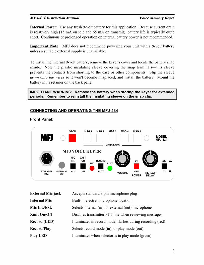
Front Panel:
External Mic jack Accepts standard 8 pin microphone plug
Internal Mic Built-in electret microphone location
Mic Int./Ext. Selects internal (in), or external (out) microphone
Xmit On/Off Disables transmitter PTT line when reviewing messages
Record (LED) Illuminates in record mode, flashes during recording (red)
Record/Play Selects record mode (in), or play mode (out)
Play LED Illuminates when selector is in play mode (green)
MFJ-434 Instruction Manual Voice Memory Keyer
4
Volume Controls volume of monitor speaker (and audio out jack)
Power On/Off Main power switch--on (in), off (out)
Repeat Delay Varies message-repeat interval (3-50 secs or 30-500 secs)
X1/X10 Multiplies message-repeat interval by x1 (out) or x10 (in)
Stop Halts message, cancels endless-loop function
Messages Selects message slots 1-5 and starts record or playback
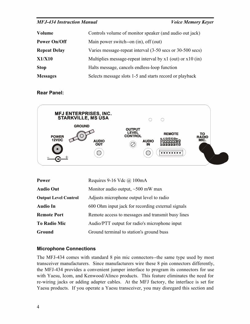
Rear Panel:
Power Requires 9-16 Vdc @ 100mA
Audio Out Monitor audio output, ~500 mW max
Output Level Control Adjusts microphone output level to radio
Audio In 600 Ohm input jack for recording external signals
Remote Port Remote access to messages and transmit busy lines
To Radio Mic Audio/PTT output for radio's microphone input
Ground Ground terminal to station's ground buss
Microphone Connections
The MFJ-434 comes with standard 8 pin mic connectors--the same type used by mosttransceiver manufacturers. Since manufacturers wire these 8 pin connectors differently,the MFJ-434 provides a convenient jumper interface to program its connectors for usewith Yaesu, Icom, and Kenwood/Alinco products. This feature eliminates the need forre-wiring jacks or adding adapter cables. At the MFJ factory, the interface is set forYaesu products. If you operate a Yaesu transceiver, you may disregard this section and

MFJ-434 Instruction Manual Voice Memory Keyer
5
use your keyer without resetting the interface jumpers. If you use an Icom orKenwood/Alinco radio, you must change the keyer's internal jumper settings to theprescribed positions before attempting to operate.
If your radio isn't an Icom or Kenwood/Alinco product, we recommend leaving theinternal jumpers in their default (Yaesu) placement Microphone pin out information formaking adapter cables is provided at the end of this section.
An internal jumper (J6) selects external microphone voltage. Some microphones requireexternal voltage to operate. This jumper supplies 0, 1.5, and 5 volts.
The simple microphone/radio setup procedures require only a few minutes of time.
IMPORTANT WARNING: The MFJ-434's internal jumpers are factory set forcompatibility with Yaesu transceivers using conventional dynamic or crystalmicrophones. When using Icom or Kenwood/Alinco products, internal jumpersmust be reset for the correct manufacturer and microphone voltage.
Setting Jumpers for Icom and Kenwood/Alinco Radios
Begin by removing screws from the sides and the top of the cabinet. Remove the cover,being careful not to stress the monitor speaker wires.
1. JMP3-JMP5: On the left side of the circuit board, locate a long set of headersextending in a line toward the rear of the cabinet. These are divided into three groupsmarked "K" JMP5 (Kenwood/Alinco), "I" JMP4 (Icom), and "Y" JMP3 (Yaesu). Atthe factory, a set of eight (8) black plastic jumper plugs were installed on the JMP3group to program your keyer for Yaesu radios. Remove all 8 of these plugs andtransfer them to the header for the type of radio you have:
Yaesu = "Y" JMP3 Icom = "I" JMP4 Kenwood/Alinco = "K" JMP5
Make sure all 8 headers in the selected group have shorting plugs installed.
2. JMP2: Next, find JMP2, a 3-pin header just to the right of JMP3-JMP5. At thefactory, a jumper plug was installed on the two rear pins marked "Y" for Yaesu. Movethis jumper to the front two pins marked I/K for Icom or Kenwood/Alinco radios.
Y = Yaesu I/K = Icom or Kenwood/Alinco
3. JMP6: There are three jumper pins near the front of the circuit board, labeled JMP6with 5V, 1.5V, and 0V markings. This jumper is normally set at 0V, which iscompatible with Yaesu and other standard dynamic and crystal microphones that donot require external voltage. If you are using a microphone that does require externalvoltage, or if your microphone does not record to the voice keyer but works normallywhen connected to the voice keyer, consult the specifications for your microphone.Place the jumpers in the setting that most closely matches the voltage specified byyour microphone manufacturer.
MFJ-434 Instruction Manual Voice Memory Keyer
6
IMPORTANT WARNING: Do not inadvertently change the jumper on HD1. Thisjumper is set on pins 7-8, and should not be moved.
Other Internal Adjustments
Please note two other important internal settings while the cover is off and the pc boardvisible:
1. Dual Gain Control, R29: This trimpot, located next to the audio isolationtransformer, sets the overall adjustment range of the Output Level Control located onthe rear panel. If you find the back panel gain control must be adjusted to an extremesetting (high or low) to provide the correct levels to your radio, you may reset R29 tobring the Output Level Control back into its center range.
2. PTT Automatic Override, JMP1: This jumper plug enables the Automatic Overridefeature that stops outgoing messages whenever the PTT switch is pressed. When theplug is removed, the automatic override function is disabled.
Microphone Connections for Other Radios
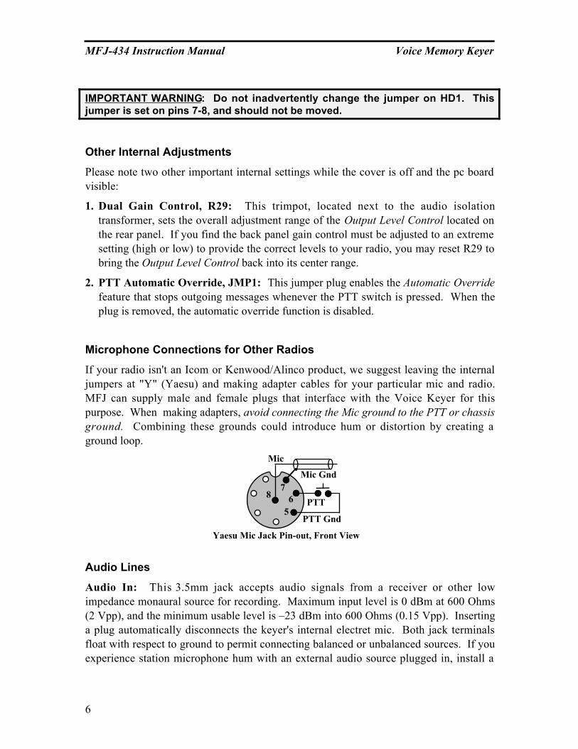
If your radio isn't an Icom or Kenwood/Alinco product, we suggest leaving the internaljumpers at "Y" (Yaesu) and making adapter cables for your particular mic and radio.MFJ can supply male and female plugs that interface with the Voice Keyer for thispurpose. When making adapters, avoid connecting the Mic ground to the PTT or chassisground. Combining these grounds could introduce hum or distortion by creating aground loop.
PTT
Mic
Mic Gnd
Yaesu Mic Jack Pin-out, Front View
87
65
PTT Gnd
Audio Lines
Audio In: This 3.5mm jack accepts audio signals from a receiver or other lowimpedance monaural source for recording. Maximum input level is 0 dBm at 600 Ohms(2 Vpp), and the minimum usable level is –23 dBm into 600 Ohms (0.15 Vpp). Insertinga plug automatically disconnects the keyer's internal electret mic. Both jack terminalsfloat with respect to ground to permit connecting balanced or unbalanced sources. If youexperience station microphone hum with an external audio source plugged in, install a

MFJ-434 Instruction Manual Voice Memory Keyer
7
600 Ohm 1:1 audio isolation transformer in the external audio line (RadioShack RS273-1374). All audio lines, balanced or unbalanced, should be grounded at one end only.
Stereo Plug Mono Plug
Audio Audio
Tip Sleeve Tip SleeveRing
Audio 680
Omit for Hi-Z source
IMPORTANT WARNING: Never exceed 3 Vdc or 3 Vpp input on the “Audio In”jack. If recorded audio is distorted, either reduce the external audio level controlor add external attenuation to reduce level. When using stereo plugs, connect thering terminal to the sleeve for 600-Ohm lines, or leave open for Hi-Z audiosources.
Audio Out: This 3.5mm jack provides a low impedance monaural output signal from thekeyer's monitor amplifier, disconnecting the internal speaker when a plug is inserted.Output is unbalanced, and the monitor amplifier delivers a maximum undistorted signallevel of approximately 4Vpp into 4 ohms (or about 500 mW RMS). The jack's tip lead is"hot" and the sleeve is connected to both signal and chassis ground. When using stereoplugs, do not wire to the ring terminal (see input jack diagram above). Note that stereoheadphones will not function properly when plugged into this jack.
Remote Port Connections
Remote message control lines are provided at the back panel via a male 8-pin IDC plug.This provides individual access to all five memory lines (MSG1-MSG5) plus the stopmessage line (Stop). All lines are isolated by a buffer, and are CMOS and TTL levelcompatible.
A special output line provides 12 Vdc at low current when the voice keyer is nottransmitting. This line goes logic low when the keyer transmits (Xmit), and can sinkmore than 20 mA. Another pin provides a control voltage ground (Gnd), for the controlsystem return path.
These lines are clearly labeled on the back panel for your convenience. The Remote PortIDC connector may be used to add a remote control box or to provide an interface point
MFJ-434 Instruction Manual Voice Memory Keyer
8
for PC driven message activation. Instructions for constructing a simple remote controlswitch box and an external PC interface are provided later in the manual.
Initial Setup
Before powering up your voice keyer, double-check all connections to your transceiver,microphone, etc. Be especially certain the power source is wired properly and delivering9-15 Vdc with the center pin positive, and that the supply can handle at least 100 mA. Ifthe supply is larger than 1 ampere, be sure you fuse the positive and negative lines. Pre-set your keyer's controls as follows:
Mic Int./Ext: Set as needed--Int for built-in mic or Ext for station's PTT mic.
Xmit: Off (out).
Rec/Play: Play (out).
Volume: 10 o'clock position.
Power: Off (out). Remember to power your transceiver before turning on the keyer.
Repeat Delay: Fully counter-clockwise (CW) for minimum delay.
X10/X1: X1 (out).
Recording A Message
1. Press POWER to ON: The green Play LED should illuminate.
2. Press REC/PLAY switch to REC: The red Rec LED should illuminate and the greenPlay LED should extinguish.
3. Choose Audio Source: Audio is available for recording from three sources--theinternal mic, external station mic, and line level Audio In jack. Select as follows:
A. Built-In Electret Mic: Set Mic switch to Int and speak normally about one footaway from the front panel. Don't crowd the mic element, or distortion may result.Note that installing a plug into the Audio In jack disables the electret mic. Removeany plug connected to the Audio In jack before attempting to use the internal mic.
B. Station Mic: Set the Mic switch to Ext and speak normally. Most station micswill not require PTT activation to record. However, mics with switched audiolines will. In this event, it's okay to press the PTT switch and speak (your radiowill key up, but no audio will be sent out over the air). If PTT keying poses aproblem, disconnect the voice keyer cable from your radio until recording iscompleted.
C. Off-Air or External Audio Source: Set Mic switch to Int and plug a line levelaudio source into the Audio In jack on the rear panel. Installing a plug in the AudioIn jack disables the electret mic. Line level sources should not exceed 0-dBm.
MFJ-434 Instruction Manual Voice Memory Keyer
9
4. Select A Message Slot: Choose from MSG1-MSG5 on the front panel. Press yourselection and watch the Rec LED (it should flash within about two seconds). The firstflash indicates recording has begun. To avoid recording "dead air", begin speaking themoment the red Rec LED starts flashing.
5. Record Your Message: The voice memory IC will record for as long as the memorybutton is held in, but no longer than the memory's capacity. The Rec LED will beginflashing rapidly to notify you when the memory time in each message block is nearlyexpired. To conserve memory and prevent accidental over writing, release thememory button immediately after your last word.
Message Memories
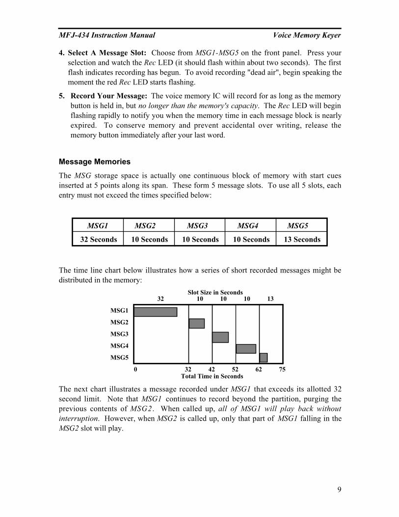
The MSG storage space is actually one continuous block of memory with start cuesinserted at 5 points along its span. These form 5 message slots. To use all 5 slots, eachentry must not exceed the times specified below:
MSG1 MSG2 MSG3 MSG4 MSG5
32 Seconds 10 Seconds 10 Seconds 10 Seconds 13 Seconds
The time line chart below illustrates how a series of short recorded messages might bedistributed in the memory:
MSG1
MSG2
MSG3
MSG4
MSG5
0 75Total Time in Seconds
32 42 52 62
32 10 10 10 13Slot Size in Seconds
The next chart illustrates a message recorded under MSG1 that exceeds its allotted 32second limit. Note that MSG1 continues to record beyond the partition, purging theprevious contents of MSG2. When called up, all of MSG1 will play back withoutinterruption. However, when MSG2 is called up, only that part of MSG1 falling in theMSG2 slot will play.

MFJ-434 Instruction Manual Voice Memory Keyer
10
MSG1
MSG2
MSG3
MSG4
MSG5
0 75Total Time in Seconds
32 42 52 62
32 10 10 10 13Slot Size in Seconds
This feature enables you to load up to a 75 second message in MSG1, should you need along recording (progressively fewer slots are available as your message grows in length).When the memory limit is reached, the red Rec LED will stop blinking and the recordfunction will stop automatically. With a little practice, you can use this protocol toextend your unit's flexibility.
Message Playback
Until you become fully familiar with your Voice Keyer's operation, we suggest practicingwith it disconnected from your transceiver. This will prevent accidental on airinterference.
1. Previewing Recorded Messages: Whenever the Xmit button is Off (out),you may select any message (MSG) in memory and listen to it on the monitorspeaker without transmitting it over the air. Monitor playback level is adjustedvia the Volume control on the keyer's front panel.
2. Transmitting Recorded Messages: Whenever the Xmit button is On (in), anymessage (MSG) you select will be transmitted over the air.
3. Single Play of a Recorded Message: To preview or transmit a message one timeonly, press the desired MSG switch briefly and release.
4. Endless Loop Playback of a Recorded Message: To preview or transmit a messagein endless loop mode, press and hold the desired MSG button for two seconds--untilthe green Play LED begins blinking. When you release the MSG button, the firstplayback will start. It will then repeat at the interval set by the Repeat Delay controlsuntil halted.
MFJ-434 Instruction Manual Voice Memory Keyer
11
5. Adjusting the Endless Loop Delay Interval: The repeat interval begins at the end ofthe recorded message. The front panel knob labeled Repeat Delay adjusts the intervalfrom 0.5-50 seconds in the X1 switch position, and from 1-500 seconds in the X10switch position. We recommend checking the interval time in preview mode (Xmitswitch Off) before putting your message on air.
6. Halting Playback of a Recorded Message: Any of the following actions will stopmessage playback immediately:
A. Press the red Stop button to halt the message in progress.
B. Press the PTT switch on your mic to halt the message in progress.
C. Press any other MSG button to halt the current message and start a new one.
7. Adjusting the Output Level Control: Before attempting to transmit recordings onair, you must set the Output Level control on the back panel for your keyer. Begin byrecording a test message into one of the MSG memories, being careful to speak atnormal levels. Preview this message after recording to make sure it's okay beforeproceeding.
Note that your transceiver's mic gain should be set to the position where you normallyrun it. The Output Level control is then adjusted to match the audio level produced byyour station microphone. If possible, use a dummy load during this adjustment procedureto avoid generating needless on-the-air interference.
A. Establish Normal Mic Level: Press the PTT and speak normally into your stationmic, noting the average RF output level and ALC reading on the transceiver's meters.
Important Note: Do not readjust transmitter Mic Gain during the following procedure.The Voice Keyer's output level should be set to match the normal output level of yourstation microphone.
B. Play Message: Make sure the keyer is in Play mode, and activate the Xmit switch(in). Now, activate your test message by pressing the appropriate MSG button. Theradio should key automatically when the message begins, and drop out when it stops.
C. Set Output Level Control: Find the Output Level screwdriver adjustment on the backpanel and adjust it so the transceiver's meter readings approximate those from livespeech. If your final adjustment falls in the bottom or top 1/4 of the pot's controlrange, we recommend resetting R29. To do this, first set the Output Level for its12:00 (mid range) setting. Then, adjust R29 for the correct transmit level. Thisadjustment centers the Output Level control range, making fine level adjustmentseasier. See Other Internal Adjustments for more details on locating and setting R29.
Self Test Mode

MFJ-434 Instruction Manual Voice Memory Keyer
12
The MFJ-434 features a self test mode for confirming correct operation. This sequenceevaluates several functions, including all MSG buttons, remote port functions, LED’s,PTT function, repeat delay pot, and delay range switch.
1. To start the self test, release all buttons (out position) and turn the Repeat Delay potfully clockwise. Next, press Stop while turning Power on.
2. The green LED should send a copyright message and software version number inMorse Code. To skip the copyright message and go straight to test, briefly press andrelease the MSG1 button.
3. Press the following buttons in the sequence shown. The green LED should blink onceper operation.
STOP Æ GREEN
MSG1 Æ GREEN
MSG2 Æ GREEN
MSG3 Æ GREEN
MSG4 Æ GREEN
MSG5 Æ GREEN
X1/X10 Æ GREEN
STOP (REMOTE) Æ GREEN
MSG1 (REMOTE) Æ GREEN
MSG2 (REMOTE) Æ GREEN
MSG3 (REMOTE) Æ GREEN
MSG4 (REMOTE) Æ GREEN
MSG5 (REMOTE) Æ GREEN
PTT Æ GREEN
4. Turn the Repeat Delay pot fully counter-clockwise, then fully clockwise. The greenLED should blink once at each end of the pot.
5. Press the Play/Rec button. The red LED should illuminate.
6. If the unit passes this test, the red LED illuminates steadily. If there is an error, afailure message describing the problem will be sent through the LED using Morsecode.
External Control Circuits
MFJ-434 Instruction Manual Voice Memory Keyer
13
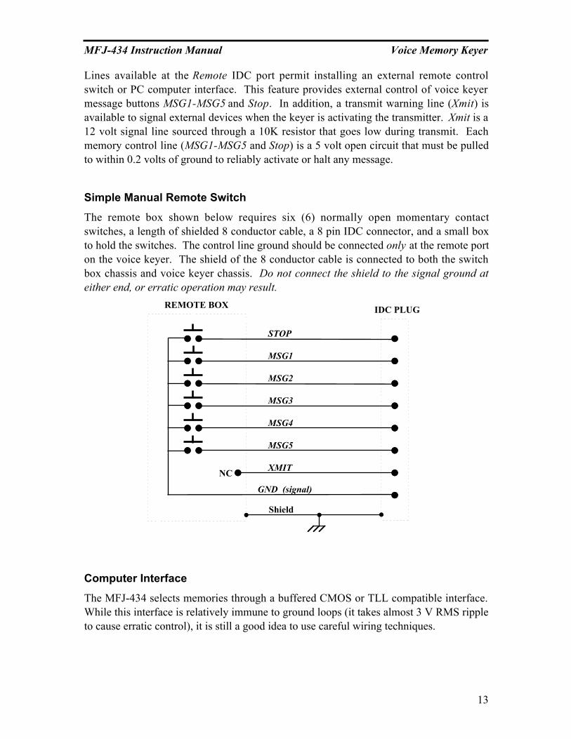
Lines available at the Remote IDC port permit installing an external remote controlswitch or PC computer interface. This feature provides external control of voice keyermessage buttons MSG1-MSG5 and Stop. In addition, a transmit warning line (Xmit) isavailable to signal external devices when the keyer is activating the transmitter. Xmit is a12 volt signal line sourced through a 10K resistor that goes low during transmit. Eachmemory control line (MSG1-MSG5 and Stop) is a 5 volt open circuit that must be pulledto within 0.2 volts of ground to reliably activate or halt any message.
Simple Manual Remote Switch
The remote box shown below requires six (6) normally open momentary contactswitches, a length of shielded 8 conductor cable, a 8 pin IDC connector, and a small boxto hold the switches. The control line ground should be connected only at the remote porton the voice keyer. The shield of the 8 conductor cable is connected to both the switchbox chassis and voice keyer chassis. Do not connect the shield to the signal ground ateither end, or erratic operation may result.
STOP
MSG1
MSG2
MSG3
MSG4
MSG5
XMIT
GND (signal)
REMOTE BOX IDC PLUG
Shield
NC
Computer Interface
The MFJ-434 selects memories through a buffered CMOS or TLL compatible interface.While this interface is relatively immune to ground loops (it takes almost 3 V RMS rippleto cause erratic control), it is still a good idea to use careful wiring techniques.

MFJ-434 Instruction Manual Voice Memory Keyer
14
We recommend using the interface circuit shown below to protect the computer fromexternal RF. Each 2N3904 transistor should be driven into saturation for reliable control.This normally requires at least 5 mA of base current.
Locate the driver transistors at the computer, and fully shield all circuitry. Be sure toground the emitters to the keyer's signal ground on the Voice-Keyer’ IDC plug only!Keep chassis ground and signal ground separate, or erratic operation may result.
R1
R2
R3
R4
R5
R8
R9
R10
R11
R12
C2
C3
C4
C5
C6
Q2
Q3
Q4
Q5
Q6
Signal Ground
Stop
MSG1
MSG2
MSG3
MSG4
MSG5
Ground
XMIT
R7
C1
Q1
R6
Computer
MEM1
MEM2
MEM3
MEM4
MEM5
Abort
R1-R6 470 Ohm
R7-R12 1 K
C1-C6 .01 uF
Q1-Q6 2N3904
Parts List
Cable
ShieldedVoice Keyer
Chassis Ground
Multi-Conductor
SW RET
The following is a cross reference for NA software:
NAABORT STOP
MEM (1-5) MSG (1-5)SW RET GND (Control Ground)
GROUND Shield or Chassis Ground
MFJ
Trouble Shooting Guide
Keyer Won't Power Up: Check power connections and cables. Also, check the voltageand polarity of your power source--it must be capable of providing 9-15 Vdc @ 100 mA.If running on 9V internal battery, check battery condition.

MFJ-434 Instruction Manual Voice Memory Keyer
15
XMIT Function and Station Mic PTT Function won't work: Check internalmicrophone jumper interface--does it match the type of transceiver you are using?
Station Mic won’t work: Check the External Microphone Power Select. Internaljumpers (JMP6) must be set to the voltage that is closest to that specified by yourmicrophone manufacturer.
Station Mic Won't Record: Press the PTT switch—the mic element may be switched.
Low or Excessive Transmit Audio on Playback: Has the Output Level Control beenset for the transmitter currently in use? Does internal trimpot R29 need to be reset tobring the Output Level Control within the transceiver's drive range?
Distorted Recordings from Audio In Jack: Are levels from your audio sourceexceeding the keyer's 0-dBm maximum input rating? If so, they must be attenuated.
Weak or Noisy Recordings from Audio In Jack: Are levels from your audio sourcebelow the -23 dBm minimum operating level? If so, they must be boosted in some way.
Voice Keyer Won't Activate PTT line on Playback: Check XMIT switch position.
Pre-recorded Messages Lost: Were higher numbered message slots accidentallyoverwritten when recording an excessively long message in a lower numbered slot?Also, check the status of the REC/PLAY switch. Was message playback attempted withthe switch in REC mode? If so, the memories may have been purged by "dead air".
No Monitor Audio: Is a jack plugged into the Audio Out connector on back? If so, theinternal monitor speaker will be disconnected.
MSG Control Erratic: Check remote jack and any remote control devices attached to it.Was the remote control ground line connected to chassis ground at some point?
PTT Switch Fails to Halt Message Palyback: Check JMP1--a shorting plug must beinstalled for the PTT override function to work.
Hum and Distortion: In ham stations where several pieces of equipment areinterconnected, unwanted hum, audio distortion, regeneration, and even sustained AFoscillations may result. This condition may be caused by RF feedback, but it's morelikely an audio system groundloop (your keyer is heavily protected against RFI). Toeliminate RF feedback as the cause, place the transmitter on a dummy load and run testsat full power level. If the audio problem disappears, it's probably RF related. If not,there's probably one or more groundloops in your station setup. Groundloops happenwhen signal grounds (mic lines, audio output lines, etc) are inadvertently connected tochassis grounds, or when audio patch cables between units are grounded at both endscreating multiple return paths. To solve the problem, begin by looking for multipleground routes and for interconnected signal and chassis grounds. If eliminating thesefaults fails to resolve the condition, try installing isolation transformers on problematicaudio lines. The more audio related equipment you interconnect, the more careful youhave to be!

MFJ-434 Instruction Manual Voice Memory Keyer
16
TECHNICAL ASSISTANCE
If you have any problem with this unit first check the appropriate section of this manual.If the manual does not reference your problem or your problem is not solved by readingthe manual, you may call MFJ Technical Service at 662-323-0549 or the MFJ Factory at662-323-5869. You will be best helped if you have your unit, manual and all informationon your station handy so you can answer any questions the technicians may ask.
You can also send questions by mail to MFJ Enterprises, Inc., 300 Industrial Park Road,Starkville, MS 39759; by Facsimile (FAX) to 662-323-6551; or by email [email protected]. Send a complete description of your problem, anexplanation of exactly how you are using your unit, and a complete description of yourstation.

MFJ-434 Instruction Manual Voice Memory Keyer
17
SCHEMATIC

MFJ-434 Instruction Manual Voice Memory Keyer
18

MFJ-434 Instruction Manual Voice Memory Keyer
19

MFJ-434 Instruction Manual Voice Memory Keyer
20