
Hands-on: Inventor HSM Express 2014 90 minutes Hands-on For ...

Page 1
MFG468778
60 MORE Inventor Tips in 60 Minutes Timothy Harrison i GET IT - Tata Technologies
Description
Looking for even more tips and tricks? There's always more to learn, and you're sure learn something new from this fast-paced sequel that will highlight even more 60 Inventor tips in 60 minutes. We'll showcase some of the less obvious commands or features and their locations within the Inventor environment. Along the way we'll look at how some of the tips work and how they might help you in your daily designing. So, strap back in! Buckle up and hang on tight—because we're taking another lap around. We've got a lot to cover and only 60 minutes to get it done.
Speaker(s)
Based in Detroit, Michigan, Timothy Harrison works as the content manager and technical consultant for i GET IT Online Training For Engineers from Tata Technologies. Focusing on online e-training for engineers using Autodesk, Inc., software, Timothy has created numerous online training courses for i GET IT in both text and video format. Courses he has created include the programs Inventor software, AutoCAD software, Revit software, Inventor Fusion software, and Fusion 360 software. Prior to working for Tata Technologies, Timothy worked in manufacturing as a designer and engineer in the tooling and special-machine field for 15 years. Most of that time was in automotive manufacturing and assembly using Inventor software.
Learning Objectives
• Discover 60 MORE tips in Inventor
• Learn where these items are in the Inventor environment.
• Learn how these tips might help your daily activities.
• Have fun!

Page 2
#1 Constraint Settings • “Where is the Green Dot?” • Application Options > Sketch >
2D Sketch > Constraint Settings

Page 3
#2 Slice Graphics
• Sketch Environment • Right Click Overflow Menu
- Slice Graphics • F7 on the keyboard

Page 4
#3 Name Parameters • Right Click on Dimension • Select Dimension Properties • Edit Name • The entered name is now the
Model Parameter instead of “d5”

Page 5
#4 Display Parameter Names
• Document Settings • Units • Display as expression
Page 6
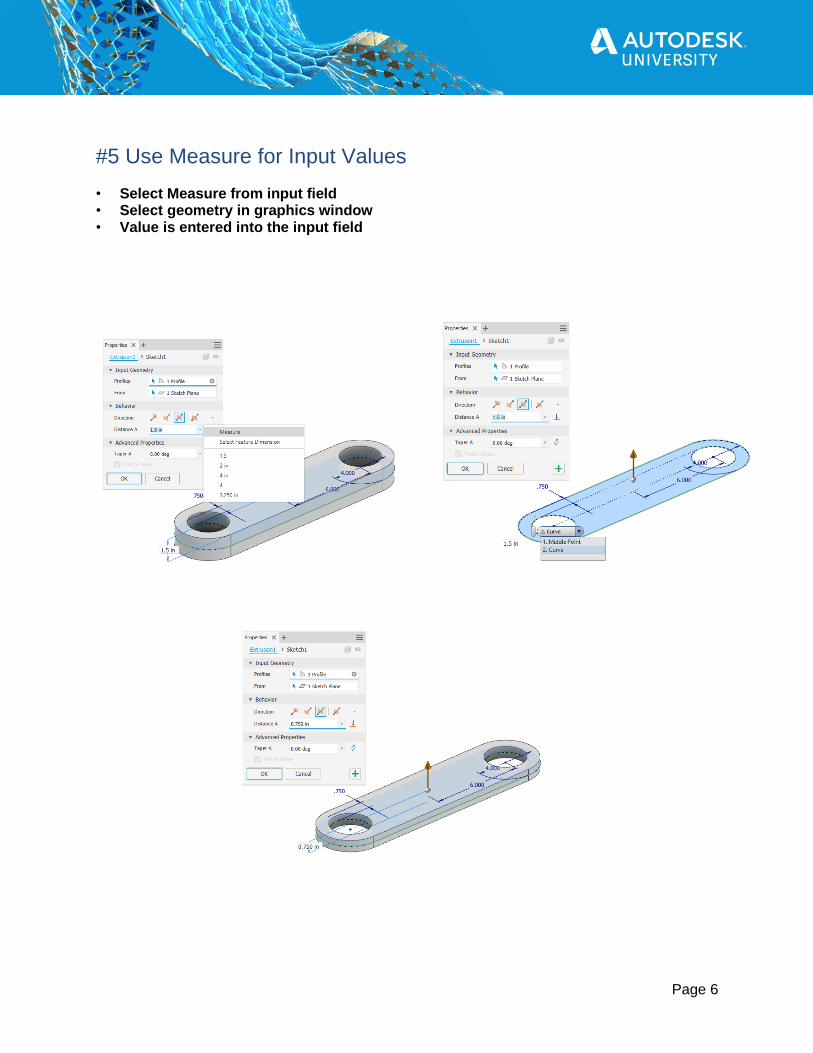
#5 Use Measure for Input Values • Select Measure from input field • Select geometry in graphics window • Value is entered into the input field
Page 7
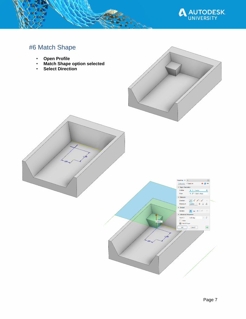
#6 Match Shape
• Open Profile • Match Shape option selected • Select Direction

Page 8
#7 Center a Hole on a Face – Method 1 • Sketch, use either dimensions, construction lines
or any combination to get a point centered on the face. • Place Sketch Point • Place Hole using Sketch Point • Downside – Requires sketch, simple
geometry, possibly dimensions

Page 9
#8 Center a Hole on a Face – Method 2
• Liner Placement of Hole • Select Feature Dimension, Divide selected
dimension in half • Downside - Requires linking of dimensional
values to stay put where you want it.

Page 10
#9 Center a Hole on a Face – Method 3 • Place Work Point - Center Point of Loop Edges • Place Hole to Work Point • Can be used on complex loops

Page 11
#10 Shaft With Thru Hole – Method 1
• Create Sketch – Diameter • Extrude Distance • Offset Work Plane – Tangent • Locate Hole (Sketch or Liner Alignment) • Place Hole • Place Chamfers
Page 12
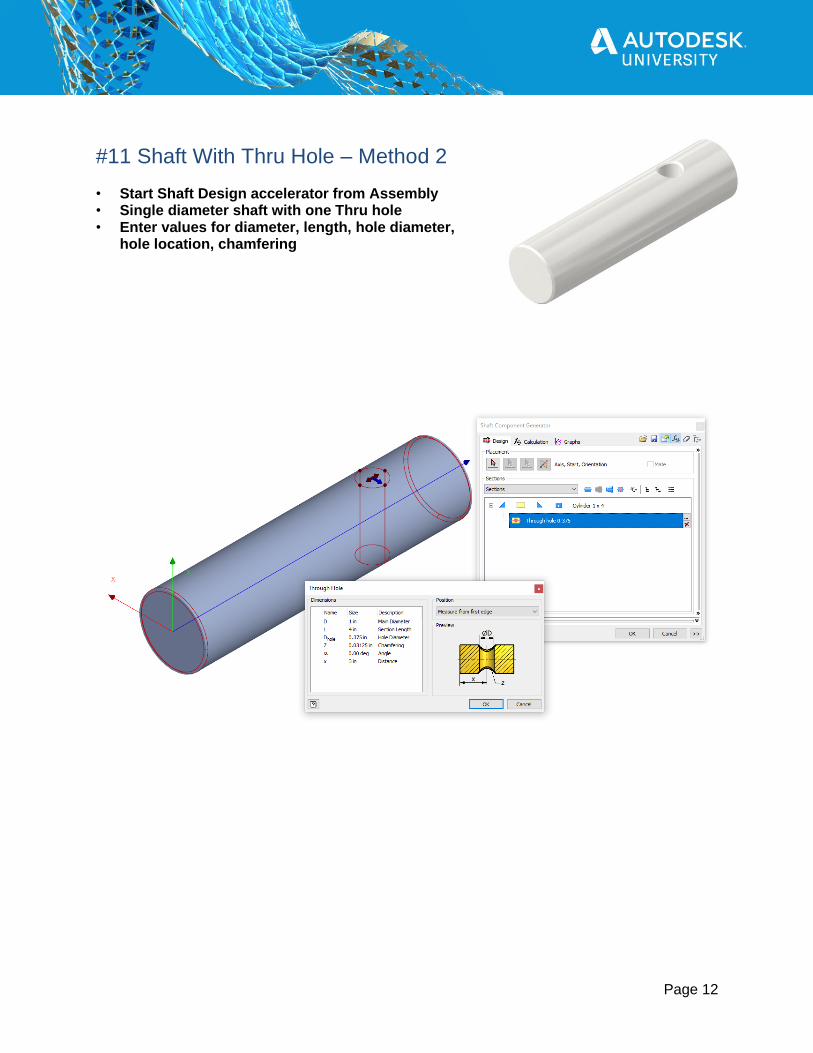
#11 Shaft With Thru Hole – Method 2 • Start Shaft Design accelerator from Assembly • Single diameter shaft with one Thru hole • Enter values for diameter, length, hole diameter,
hole location, chamfering

Page 13
#12 Partial Chamfer
• Select Single Edge, Edge Chain option • Enter Distance • Select Edge • On Partial tab, Enter To Start, Chamfer, and/or To End

Page 14
#13 Emboss Text • Create a 2D sketch, and add text to the sketch • Start the Emboss command • Select the sketch text at the Profile, Select direction options, Enter Depth • Select Wrap to Face to make emboss normal to face selected • Select an appearance to be applied to the emboss •

Page 15
#14 Create Actual White Appearance
• Set appearance to “Snow” • In the Appearance Browser, Edit the Snow appearance • On the Appearance Editor, check On Self Illumination
And set Luminance to “Frosted Bulb” • Note: Self Illuminated appearances
will affect renderings

Page 16
#15 Select Tangencies • Right Click on Face > Select Tangencies • All tangent faces are selected | Also works on Edges

Page 17
#16 Dark Theme UI
• Application Options > Dark (pre-release) • Dark theme is still in pre-release, updates
and changes possible.

Page 18
#17 Auto-hide Dialog Box • Right Click dialog box, select Auto-hide
Page 19
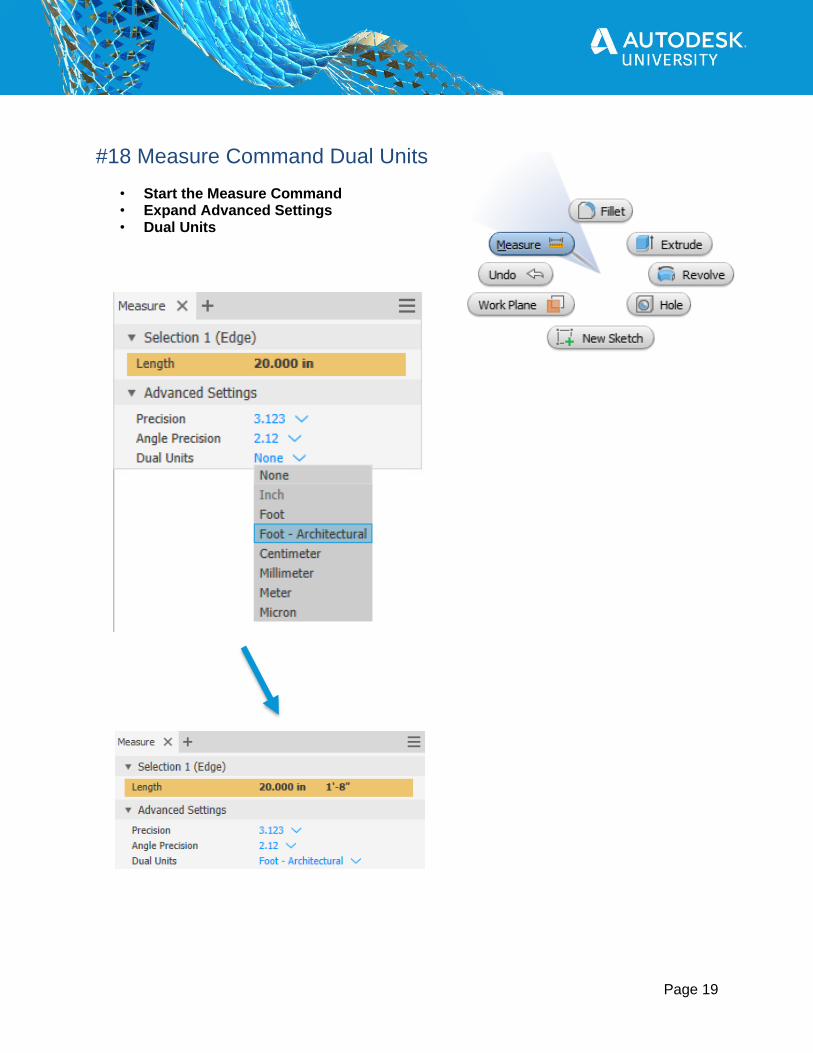
#18 Measure Command Dual Units
• Start the Measure Command • Expand Advanced Settings • Dual Units

Page 20
#19 Template Folder • Default location C:\Users\Public\Documents\Autodesk\Inventor 2021\Templates\ • Create new folder in Windows Explorer, Place template files in folder • Note: Template location set in Project File

Page 21
#20 Shortcut Hotkeys
• Over 300 Shortcuts, most are context sensitive • https://www.autodesk.com/shortcuts/inventor

Page 22
#21 Display Extended Information • Application Options > Part tab • Display extended information after feature node in browser

Page 23
#22 Annotation Scale
• Application Options > General • Annotation Scale • Set between 0.5 - 5
Annotation Scale: 1 Annotation Scale: 1 Annotation Scale: 2

Page 24
#23 Display Component Names After Relationship Names • Application Options > Assembly • Display component names
after relationship names

Page 25
#24 Customize Team Web
• Getting Started > My Home > Team Web • Application Options > File • Team WEB

Page 26
#25 Inventor Read-Only Mode • Replaced Inventor View • Anyone can use to view Autodesk Inventor files
(.ipt, .iam, .idw, .dwg, .ipn, .ide) • Windows Menu > Autodesk Inventor 2021 > Inventor Read-Only Mode 2021

Page 27
#26 Export to DWF
• File > Export > Export to DWF • Anyone can open with free Autodesk program
Design Review installed • https://www.autodesk.com/products/design-review/

Page 28
#27 Export 3D PDF • File > Export > Export to 3D PDF • Anyone can open with PDF Viewer installed

Page 29
#28 Share to Autodesk Viewer (Cloud)
• File > Export > Export to 3D PDF • Anyone can open with PDF Viewer installed
Page 30
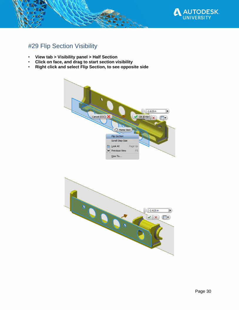
#29 Flip Section Visibility • View tab > Visibility panel > Half Section • Click on face, and drag to start section visibility • Right click and select Flip Section, to see opposite side

Page 31
#30 Turn Off Save Reminder
• Application Options > Prompts • Save Reminder • Do Not Ever Prompt Again
Page 32
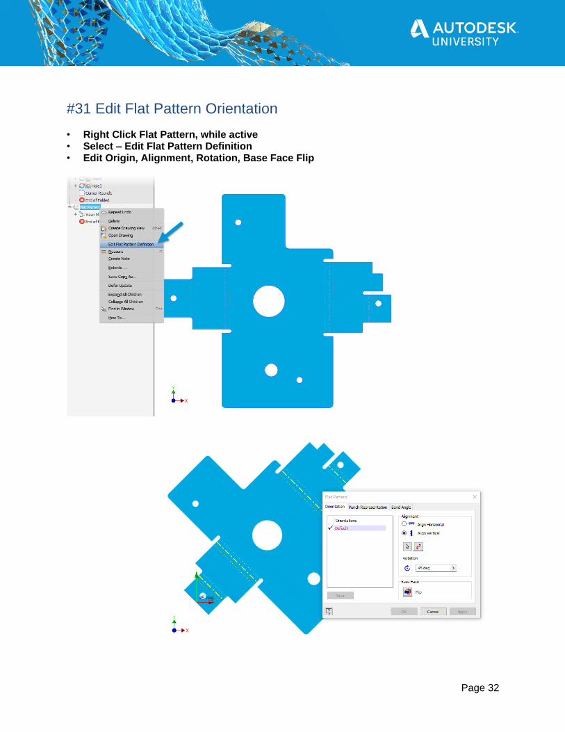
#31 Edit Flat Pattern Orientation • Right Click Flat Pattern, while active • Select – Edit Flat Pattern Definition • Edit Origin, Alignment, Rotation, Base Face Flip

Page 33
#32 Sheet Metal Hem Interference
• Create Flanges • Create One Hem edge • Unfold • Create Hem edge on remaining flanges • Refold

Page 34
#33 Mirror Components • Mirror Components Pattern • Reuse Components
New Mirrored Component Created Mirrored Reused Component
Page 35
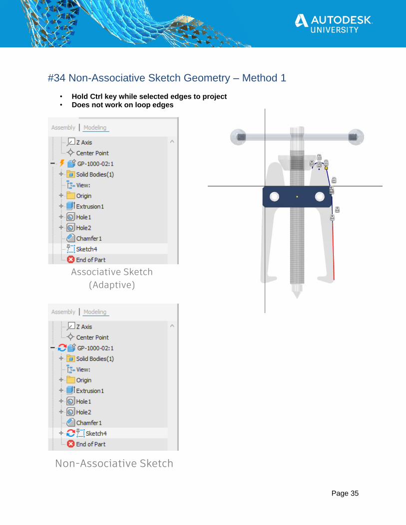
#34 Non-Associative Sketch Geometry – Method 1
• Hold Ctrl key while selected edges to project • Does not work on loop edges
Associative Sketch
(Adaptive)
Non-Associative Sketch

Page 36
#35 Non-Associative Sketch Geometry – Method 2 • Application Options • Cross part geometry project - Enable associative edge/loop geometry projection - Enable associative sketch geometry projection

Page 37
#36 Automatically Rename Browser Nodes
• Assemble tab > Productivity panel > Rename Browser Nodes • Select between:
- Filename - Part Number - Default

Page 38
#37 Assembly Folders • Right Click Assembly in Browser > Create New Folder • Name Folder • Drag and Drop components into Folder • Subfolders can be created

Page 39
#38 Demote Components
• Select Components > Right Click > Demote • Create In-Place Component • File > Export > Export to 3D PDF • Components added to sub-assembly • Relationships are maintained

Page 40
#39 Promote Components • Select Components in sub-assembly > Right Click > Promote • Components moved up to parent assembly • Relationships maintained • Note: Sub-Assembly remains even if no components in it

Page 41
#40 Component Transparent
• Select component either in graphics window or browser
• Transparent Hotkey Alt + T
Page 42
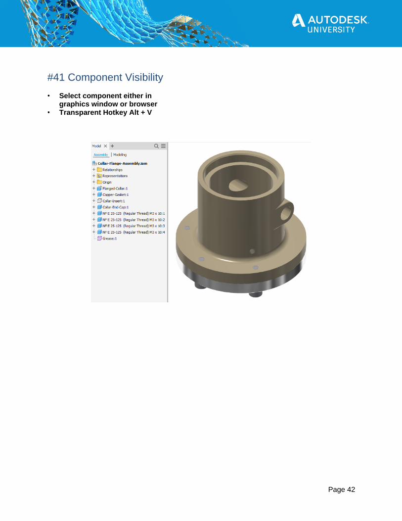
#41 Component Visibility • Select component either in
graphics window or browser • Transparent Hotkey Alt + V

Page 43
#42 Create Virtual Components
• Assemble tab > Component panel > Create • Name Component – Check Virtual Component • Use Virtual Components to add parts to your Inventor BOM that you might not
normally model

Page 44
#43 Associate Text Note With Drawing View • Place note as Leader Text to the view • Right Click the Leader Text, Select
Delete Leader from the shortcut menu • Text Note will now be associated to the view

Page 45
#44 Detached Balloon Will Not Reattach
• Default when placing balloons is Edges • When balloon is detached, leader placement is now controlled
by Selection Priority • If Part Priority is selected then you can not reattach
the balloon • Make sure Edge Priority is selected before reattaching

Page 46
#45 Replace Model Referenced • Manage tab > Modify panel > Replace Model Reference • Select Model Reference • Search for new Reference • Click OK • Views Update

Page 47
#46 Suppress Drawing View
• Right Click View in Browser, Select Suppress • Suppressing parent view does not effect child view

Page 48
#47 Align Balloons Vertical or Horizonal • Select all balloons to align • Right Click > Select Horizonal Offset or Vertical Offset • Balloons are lined up spaced relative to their original
Page 49
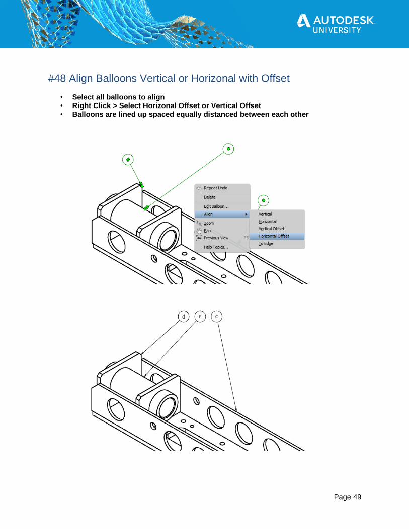
#48 Align Balloons Vertical or Horizonal with Offset
• Select all balloons to align • Right Click > Select Horizonal Offset or Vertical Offset • Balloons are lined up spaced equally distanced between each other
Page 50
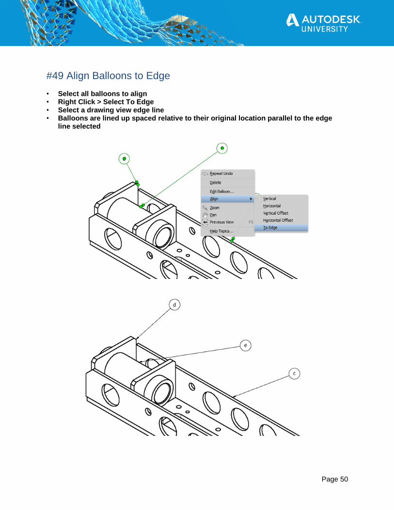
#49 Align Balloons to Edge • Select all balloons to align • Right Click > Select To Edge • Select a drawing view edge line • Balloons are lined up spaced relative to their original location parallel to the edge
line selected

Page 51
#50 Hide Drawing View Lines
• Select lines to be hidden • Right Click View • Select Visibility

Page 52
#51 Show Lines Hidden From Drawing View • Right Click View • Select Shown Hidden Edges • Select lines to show
Page 53
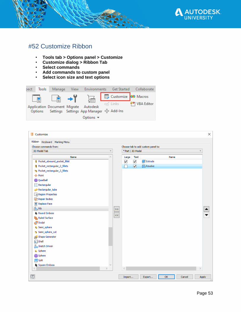
#52 Customize Ribbon
• Tools tab > Options panel > Customize • Customize dialog > Ribbon Tab • Select commands • Add commands to custom panel • Select icon size and text options

Page 54
#53 Customize Keyboard Hotkeys • Tools tab > Options panel > Customize • Customize dialog > Keyboard Tab • Select field next to Command • Enter key stroke

Page 55
#54 Customize Marking Menu
• Tools tab > Options panel > Customize • Customize dialog >
Marking Menu Tab • Select Environment &
Sub Environment • Select Menu Location,
then select command • Use Classic Context Menu

Page 56
#55 Move the Quick Access Toolbar • Click Customize Quick Access
Toolbar drop down menu • Select Show Below the Ribbon

Page 57
#56 Add Command to Quick Access Toolbar
• Right Click on command in the Ribbon bar • Select Add to Quick Access Toolbar

Page 58
#57 Remove Command from Quick Access Toolbar • Right Click on command in the Quick Access Toolbar • Select Remove from Quick Access Toolbar

Page 59
#59 Backup Your Settings!
• Application Options • Export - .XML file to save custom settings • Import - .XML file to restore custom settings

Page 60
#60 Autodesk Inventor Reset • Reset Autodesk Inventor back to factor install • Windows Menu > Autodesk Inventor 2021 > Inventor Reset Utility • Reset Utility does NOT give you the option
to backup your settings

Page 61