MF271 Rogers Rocket Hub - Support Home Page · 5 Interface Description Port/Button Description ....
16
MF271 Rogers Rocket Hub
Transcript of MF271 Rogers Rocket Hub - Support Home Page · 5 Interface Description Port/Button Description ....

MF271 Rogers Rocket Hub

�

�
LEGAL INFORMATION
Copyright © �0�4 ZTE CORPORATION.
All rights reserved.
No part of this publication may be excerpted, reproduced, translated or utilized in any form or by any means, electronic or mechanical, including photocopying and microfilm, without the prior written permission of ZTE Corporation.
The manual is published by ZTE Corporation. We reserve the right to make modifications on print errors or update specifica-tions without prior notice.
Version No. : R�.0

�
Getting to Know Your DeviceThe device operates on the 4G/3G/HSPA+/LTE networks and supports voice and data service.
Indicators

�
Indicator State Description
(Power
& battery)
Green steadyExternal power supply is working normally
Green blinking
Battery power is more than 50%
Yellow blinkingBattery power is less than �0%-50%.
Red blinking
Battery power is less than �0%
OffPower is off or external power supply is working abnormally.
(Voice-
mail)
Green blinking New voicemail.
Off No new voicemail.
(Infor-
mation)
Green blinkingCheck Web UI: New SMS, data balance, Micro-SIM is-sue and etc.
Off No need to check Web UI.
4
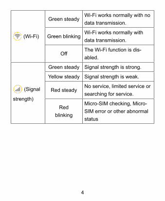
(Wi-Fi)
Green steadyWi-Fi works normally with no data transmission.
Green blinkingWi-Fi works normally with data transmission.
Off The Wi-Fi function is dis-abled.
(Signal
strength)
Green steady Signal strength is strong.
Yellow steady Signal strength is weak.
Red steadyNo service, limited service or searching for service.
Red blinking
Micro-SIM checking, Micro-SIM error or other abnormal status

5
Interface Description
Port/Button Description
�. WPSPress to enable the Wi-Fi Protected Setup.
�. PHONE�/PHONE�Standard RJ�� connector for tele-phone.
�. ETHERNET Ethernet connector for computer.
4. POWER INPUTConnector to the external power supply.
5. ON/OFF Turn the device ON or OFF.

�
Installation GuideInstalling the Micro-SIM Card and battery�. Slide the back cover and remove it
2. Insert the Micro-SIM card.

�
�. Insert the battery.
4. Replace the back cover.
Connecting Your DevicesFollow the numbers to connect your devices.
�
Switching On Your Device1. Turn the ON/OFF button on to get started. Make sure that
the phone is on hook before you power it on.2. Wait 1 ~ 2 minutes and then the Power and battery indica-
tor should be lit on.
Connecting to the InternetVia Ethernet Go to your favorite website on the PC connected to your de-vice via Ethernet cable to confirm your Internet connection.
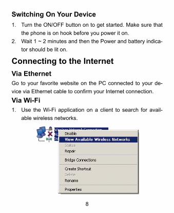
Via Wi-Fi�. Use the Wi-Fi application on a client to search for avail-
able wireless networks.

�
NOTE: Set the client to obtain an IP address automatically. For the detailed procedure, refer to Configuring Your PC. The client gets an IP address, for example, ���.���.0.�0�.�. Select the SSID of your device, and then click Connect.
NOTE:You can find the default SSID on the label of your device.

�0
3. Enter the password, and then click Connect.
NOTE:You may need to enter the password for the Wi-Fi connection. You can view the label on your device to get the default pass-word. 4. Wait until the client is connected to your device success-
fully.5. Go to your favorite website to confirm your Internet con-
nection.

��
Configuring Your PCThe following procedure describes how to configure the Inter-net Protocol in the Windows XP operating system for your Wi-Fi connection.�. Right-click My Network Places and select Properties.

��
�. Right-click Wireless Network Connection and select Properties.

��
�. Select Internet Protocol (TCP/IP) and click Properties.

�4
4. Select Obtain an IP address automatically and Obtain DNS server address automatically, and click OK.
For more information, please refer to the detailed User Guide online at www.rogers.com/userguide.com.