MEX_101-ch10
36
Note: The source of the technical material in this volume is the Professional Engineering Development Program (PEDP) of Engineering Services. Warning: The material contained in this document was developed for Saudi Aramco and is intended for the exclusive use of Saudi Aramco’s employees. Any material contained in this document which is not already in the public domain may not be copied, reproduced, sold, given, or disclosed to third parties, or otherwise used in whole, or in part, without the written permission of the Vice President, Engineering Services, Saudi Aramco. Chapter : Mechanical For additional information on this subject, contact File Reference: MEX-101.11 PEDD Coordinator on 874-6556 Engineering Encyclopedia Saudi Aramco DeskTop Standards PIPELINES REPAIR AND MAINTENANCE
-
Upload
jahangir-khan -
Category
Documents
-
view
43 -
download
0
description
nice book
Transcript of MEX_101-ch10

Note: The source of the technical material in this volume is the Professional Engineering Development Program (PEDP) of Engineering Services.
Warning: The material contained in this document was developed for Saudi Aramco and is intended for the exclusive use of Saudi Aramco’s employees. Any material contained in this document which is not already in the public domain may not be copied, reproduced, sold, given, or disclosed to third parties, or otherwise used in whole, or in part, without the written permission of the Vice President, Engineering Services, Saudi Aramco.
Chapter : Mechanical For additional information on this subject, contact File Reference: MEX-101.11 PEDD Coordinator on 874-6556
Engineering Encyclopedia Saudi Aramco DeskTop Standards
PIPELINES REPAIR AND MAINTENANCE

Engineering Encyclopedia Piping, Pipelines & Valves
Pipelines Repair and Maintenance
Saudi Aramco DeskTop Standards i
Section Page
INFORMATION ............................................................................................................... 3
INTRODUCTION............................................................................................................. 3
PIPELINE / PIPING DEFECTS AND THEIR ACCEPTANCE CRITERIA ........................ 4
Weld Defects ............................................................................................................. 4
ASME B31.3 Systems, In Plant Piping ................................................................. 6
ASME B31.4......................................................................................................... 6
ASME B31.8......................................................................................................... 7
Dents ......................................................................................................................... 7
ASME 31.4 ........................................................................................................... 7
ASME 31.8 ........................................................................................................... 8
Dent Repairs......................................................................................................... 8
Cracks........................................................................................................................ 8
Corrosion ................................................................................................................... 9
Uniform Corrosion ................................................................................................ 9
Pitting ................................................................................................................... 9
Hydrogen Blisters ............................................................................................... 10
PIPELINES ISOLATIONS AND REPAIRS .................................................................... 12
Pipeline Isolations .................................................................................................... 12
HOT TAPING PROCEDURE AND CALCULATIONS.................................................... 14
Preparation Requirements for Hot Taps (Form SA-7627-ENG).......................... 19
Inspection Requirements.................................................................................... 20
Testing Requirements ........................................................................................ 20
Calculations........................................................................................................ 21
PIPELINES REPAIR METHODS .................................................................................. 24
Welded Pipe Patches ......................................................................................... 24
Engineering Encyclopedia Piping, Pipelines & Valves
Pipelines Repair and Maintenance
Saudi Aramco DeskTop Standards ii
Weld Build-up ..................................................................................................... 24
Repair Sleeves ................................................................................................... 25
Pressure Containing Repair Sleeves.................................................................. 25
Non Pressure Containing repair Sleeves............................................................ 25
ADDENDUM ................................................................................................................. 29
Attachment 1............................................................................................................ 30
Attachment 2: Hydrogen Induced Cracking (HIC) Decision Tree Source SAEP- 310 “Pipelines Repair and Maintenance” .................................................... 34
Hydrogen Induced Cracking (HIC) Decision Tree (Continued) ................................ 35
LIST OF FIGURES
Figure 1. Different Types of Pipeline Plugs ................................................................. 13
Figure 2. Basic Arrangement of a Hot Tap ................................................................... 16
Figure 3. Typical Procedure of Plugging Without Shutdown ........................................ 18
Figure 4. Full Encirclement Repair Sleeve .................................................................. 26
Figure 5. Butt-Strap Repair Sleeve .............................................................................. 27
Figure 6. Clock Spring Repair Sleeve ......................................................................... 27
Figure 7. Strong Pack Repair Sleeve .......................................................................... 28
Figure 8. Acceptance Criteria for Welds ...................................................................... 31

Engineering Encyclopedia Piping, Pipelines & Valves
Pipelines Repair and Maintenance
Saudi Aramco DeskTop Standards 3
INFORMATION
INTRODUCTION
The previous two modules discussed weld defects and types of weld inspection, and how to fill out safety instruction sheets before the piping system goes into operation. This module discusses how the engineer determines if a defect in an existing piping system is acceptable and, if not acceptable, the various methods of repair. Once the piping system is in operation, it must be maintained such that it remains reliable and safe. This requires the engineer to identify the types of defects that may occur in piping, as discussed in MEX 101.09, and determine the defect's acceptability based on industry and Saudi Aramco requirements. Various methods of repair may be used if the defect is not acceptable. The engineer must be able to match the defect with a potential repair method. If pipe replacement is necessary, the engineer must identify the design, calculations, inspection, and testing requirements for hot tapping and stoppling.
Engineering Encyclopedia Piping, Pipelines & Valves
Pipelines Repair and Maintenance
Saudi Aramco DeskTop Standards 4
PIPELINE / PIPING DEFECTS AND THEIR ACCEPTANCE CRITERIA
Once an unacceptable pipeline defect is found, it is evaluated and accordingly the pipeline repair procedure is issued. Based on the defect type and severity, the pipeline could be repaired, replaced or derated (reduce the pipeline design pressure). The pipeline can be repaired during shutdown or while in service.
Once a defect is identified through the examination methods that were discussed in the previous module, the engineer should be able to reference the applicable piping code and Saudi Aramco Engineering Procedure (SAEP) to determine the acceptability of the defect. The piping codes such as ASEME B31 and API 1104 provide acceptance criteria for the various types of defects. However, their focus is on new piping systems and the quality level required before a piping system can be placed into service for the first time. In existing piping systems, engineering evaluations are necessary to determine if the system still can be safely operated with un-repaired defects. The applicable piping code is normally the starting point for such evaluations, but it is often necessary to go further.
This section discusses the primary types of defects and their acceptance criteria based on ASME 31 Code and SAEP requirements.
Weld Defects
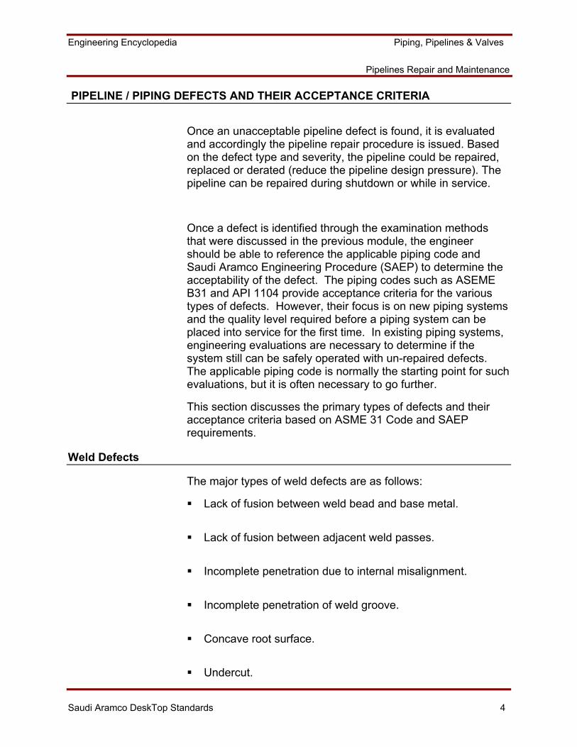
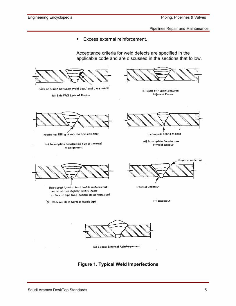
The major types of weld defects are as follows:
Lack of fusion between weld bead and base metal.
Lack of fusion between adjacent weld passes.
Incomplete penetration due to internal misalignment.
Incomplete penetration of weld groove.
Concave root surface.
Undercut.
Engineering Encyclopedia Piping, Pipelines & Valves
Pipelines Repair and Maintenance
Saudi Aramco DeskTop Standards 5
Excess external reinforcement.
Acceptance criteria for weld defects are specified in the applicable code and are discussed in the sections that follow.
Figure 1. Typical Weld Imperfections
Engineering Encyclopedia Piping, Pipelines & Valves
Pipelines Repair and Maintenance
Saudi Aramco DeskTop Standards 6
ASME B31.3 Systems, In Plant Piping
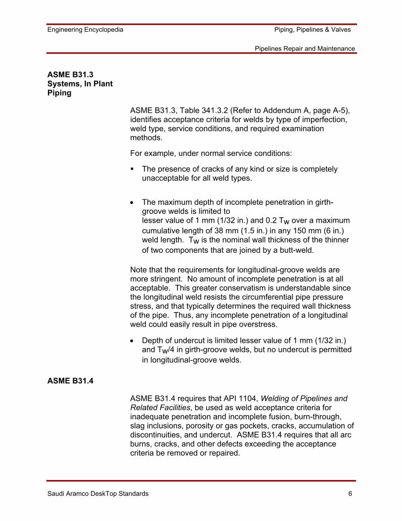
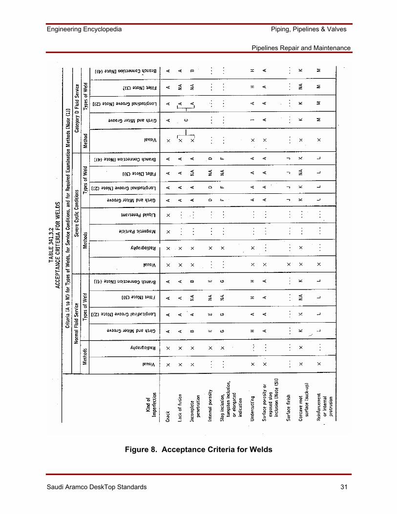
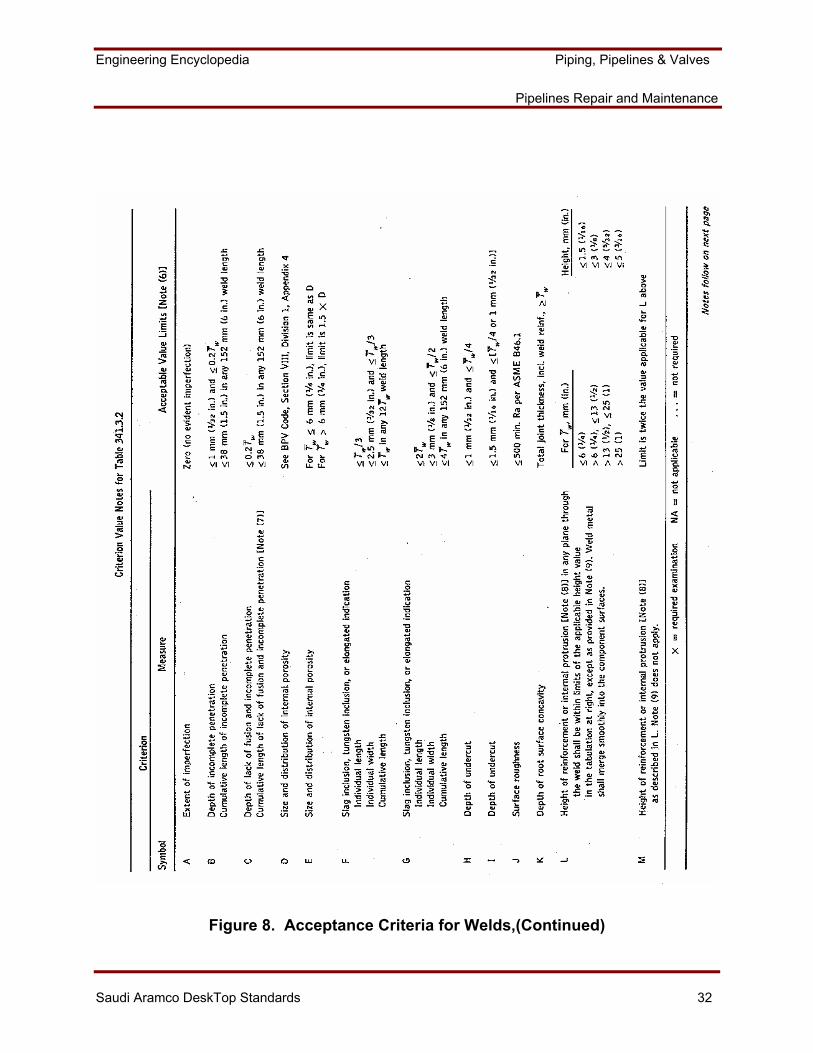
ASME B31.3, Table 341.3.2 (Refer to Addendum A, page A-5), identifies acceptance criteria for welds by type of imperfection, weld type, service conditions, and required examination methods.
For example, under normal service conditions:
The presence of cracks of any kind or size is completely unacceptable for all weld types.
• The maximum depth of incomplete penetration in girth-groove welds is limited to lesser value of 1 mm (1/32 in.) and 0.2 Tw over a maximum cumulative length of 38 mm (1.5 in.) in any 150 mm (6 in.) weld length. Tw is the nominal wall thickness of the thinner of two components that are joined by a butt-weld.
Note that the requirements for longitudinal-groove welds are more stringent. No amount of incomplete penetration is at all acceptable. This greater conservatism is understandable since the longitudinal weld resists the circumferential pipe pressure stress, and that typically determines the required wall thickness of the pipe. Thus, any incomplete penetration of a longitudinal weld could easily result in pipe overstress.
• Depth of undercut is limited lesser value of 1 mm (1/32 in.) and Tw/4 in girth-groove welds, but no undercut is permitted in longitudinal-groove welds.
ASME B31.4
ASME B31.4 requires that API 1104, Welding of Pipelines and Related Facilities, be used as weld acceptance criteria for inadequate penetration and incomplete fusion, burn-through, slag inclusions, porosity or gas pockets, cracks, accumulation of discontinuities, and undercut. ASME B31.4 requires that all arc burns, cracks, and other defects exceeding the acceptance criteria be removed or repaired.
Engineering Encyclopedia Piping, Pipelines & Valves
Pipelines Repair and Maintenance
Saudi Aramco DeskTop Standards 7
ASME B31.8
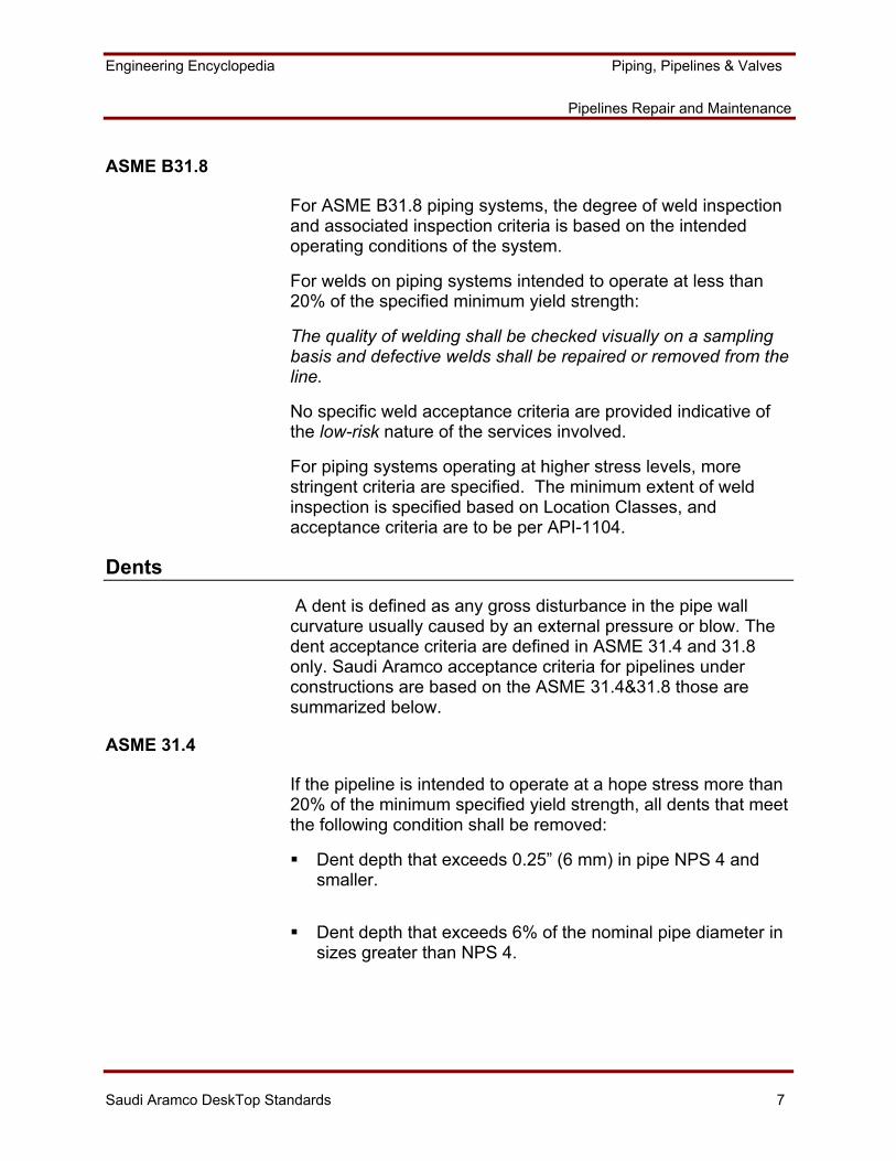
For ASME B31.8 piping systems, the degree of weld inspection and associated inspection criteria is based on the intended operating conditions of the system.
For welds on piping systems intended to operate at less than 20% of the specified minimum yield strength:
The quality of welding shall be checked visually on a sampling basis and defective welds shall be repaired or removed from the line.
No specific weld acceptance criteria are provided indicative of the low-risk nature of the services involved.
For piping systems operating at higher stress levels, more stringent criteria are specified. The minimum extent of weld inspection is specified based on Location Classes, and acceptance criteria are to be per API-1104.
Dents
A dent is defined as any gross disturbance in the pipe wall curvature usually caused by an external pressure or blow. The dent acceptance criteria are defined in ASME 31.4 and 31.8 only. Saudi Aramco acceptance criteria for pipelines under constructions are based on the ASME 31.4&31.8 those are summarized below.
ASME 31.4
If the pipeline is intended to operate at a hope stress more than 20% of the minimum specified yield strength, all dents that meet the following condition shall be removed:
Dent depth that exceeds 0.25” (6 mm) in pipe NPS 4 and smaller.
Dent depth that exceeds 6% of the nominal pipe diameter in sizes greater than NPS 4.
Engineering Encyclopedia Piping, Pipelines & Valves
Pipelines Repair and Maintenance
Saudi Aramco DeskTop Standards 8
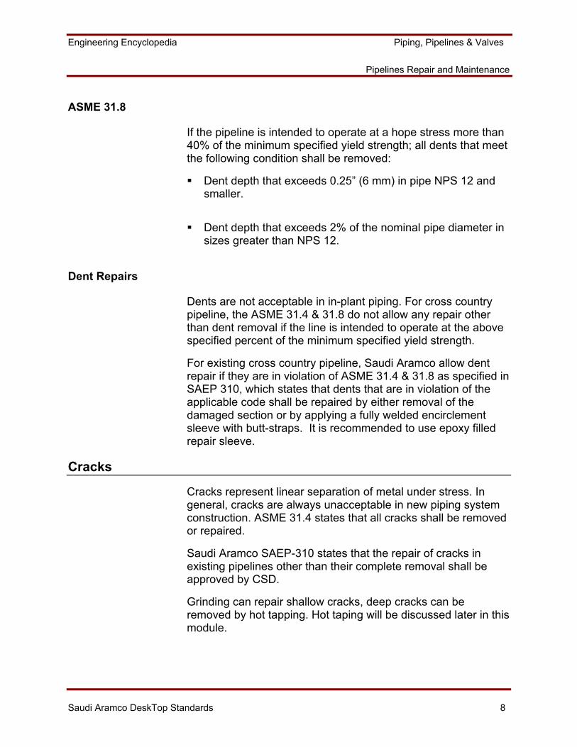
ASME 31.8
If the pipeline is intended to operate at a hope stress more than 40% of the minimum specified yield strength; all dents that meet the following condition shall be removed:
Dent depth that exceeds 0.25” (6 mm) in pipe NPS 12 and smaller.
Dent depth that exceeds 2% of the nominal pipe diameter in sizes greater than NPS 12.
Dent Repairs
Dents are not acceptable in in-plant piping. For cross country pipeline, the ASME 31.4 & 31.8 do not allow any repair other than dent removal if the line is intended to operate at the above specified percent of the minimum specified yield strength.
For existing cross country pipeline, Saudi Aramco allow dent repair if they are in violation of ASME 31.4 & 31.8 as specified in SAEP 310, which states that dents that are in violation of the applicable code shall be repaired by either removal of the damaged section or by applying a fully welded encirclement sleeve with butt-straps. It is recommended to use epoxy filled repair sleeve.
Cracks
Cracks represent linear separation of metal under stress. In general, cracks are always unacceptable in new piping system construction. ASME 31.4 states that all cracks shall be removed or repaired.
Saudi Aramco SAEP-310 states that the repair of cracks in existing pipelines other than their complete removal shall be approved by CSD.
Grinding can repair shallow cracks, deep cracks can be removed by hot tapping. Hot taping will be discussed later in this module.
Engineering Encyclopedia Piping, Pipelines & Valves
Pipelines Repair and Maintenance
Saudi Aramco DeskTop Standards 9
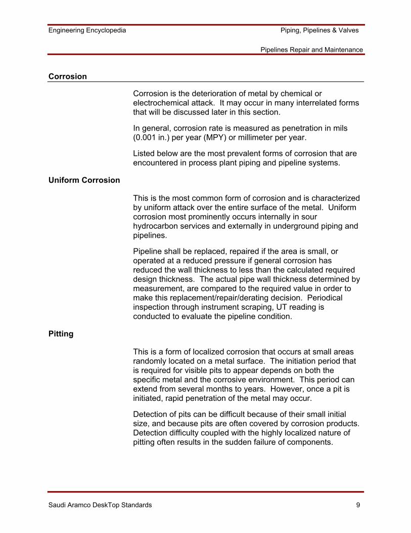
Corrosion
Corrosion is the deterioration of metal by chemical or electrochemical attack. It may occur in many interrelated forms that will be discussed later in this section.
In general, corrosion rate is measured as penetration in mils (0.001 in.) per year (MPY) or millimeter per year.
Listed below are the most prevalent forms of corrosion that are encountered in process plant piping and pipeline systems.
Uniform Corrosion
This is the most common form of corrosion and is characterized by uniform attack over the entire surface of the metal. Uniform corrosion most prominently occurs internally in sour hydrocarbon services and externally in underground piping and pipelines.
Pipeline shall be replaced, repaired if the area is small, or operated at a reduced pressure if general corrosion has reduced the wall thickness to less than the calculated required design thickness. The actual pipe wall thickness determined by measurement, are compared to the required value in order to make this replacement/repair/derating decision. Periodical inspection through instrument scraping, UT reading is conducted to evaluate the pipeline condition.
Pitting
This is a form of localized corrosion that occurs at small areas randomly located on a metal surface. The initiation period that is required for visible pits to appear depends on both the specific metal and the corrosive environment. This period can extend from several months to years. However, once a pit is initiated, rapid penetration of the metal may occur.
Detection of pits can be difficult because of their small initial size, and because pits are often covered by corrosion products. Detection difficulty coupled with the highly localized nature of pitting often results in the sudden failure of components.
Engineering Encyclopedia Piping, Pipelines & Valves
Pipelines Repair and Maintenance
Saudi Aramco DeskTop Standards 10
Pitting is most likely to occur in stagnant or low-velocity fluids where there is a break in the electrical continuity of a metal surface in contact with an electrolyte. Examples of such discontinuities are rough spots, scratches, or indentations.
ASME is the only B31 Code that has specific criteria for evaluating pitting. These are discussed below.
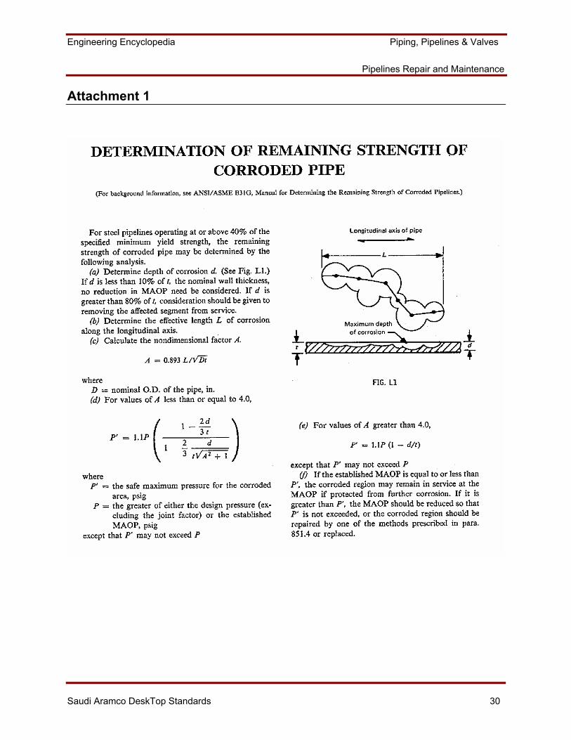
ASME B31G Pitting Evaluation — Pipe shall be repaired, 4replaced, or operated at a reduced pressure if localized corrosion pitting has reduced the wall thickness to less than the calculated minimum required design thickness, decreased by an amount equal to the manufacturing tolerance applicable to the pipe or component. This applies if the length of the pitted area is greater than that permitted by the equation shown below. The following method applies only when the depth of the corrosion pit is less than 80% of the nominal wall thickness of the pipe. This method does not apply to corrosion in the girth or longitudinal weld or related heat-affected zones. The corroded area must be clean to bare metal. Care shall be taken in cleaning corroded areas of a pressurized pipeline when the degree of corrosion is significant. Refer to the Addendum A, page A-2, Attachment 1: Determination of Remaining Strength of Corroded Pipe.
Hydrogen Blisters
Another type of corrosion phenomenon, which can occur in piping is hydrogen blistering. In this case, hydrogen, in atomic form, diffuses into the surface of the carbon steel pipe. The atomic hydrogen then collects in discontinuities of the metal and forms molecular hydrogen. Because molecular hydrogen will not diffuse through the steel, the pressure builds up inside the voided area and causes a lamination of the metal. The laminated area is confined to a local area and appears on the surface of the metal in the form of blisters or fissures. Hydrogen blistering occurs most commonly in wet sour service.
Evidence of hydrogen activity can sometimes be detected on the external surfaces of pipe by the blistering or flaking of paint films, or even by blistering of the steel itself. If test probes are, or can be, located in the suspect areas, hydrogen activity can be confirmed by cleaning the surface back to bare metal and applying two coats of a flexible paint.
Engineering Encyclopedia Piping, Pipelines & Valves
Pipelines Repair and Maintenance
Saudi Aramco DeskTop Standards 11
Hydrogen blisters do not necessarily affect the strength or integrity of a pipe. However, there are no simple criteria that may be used to evaluate their acceptability. An engineering evaluation is required to determine if there is adequate local strength remaining in the pipe with the blisters. Discussion of this evaluation is beyond the scope of this course. Blisters typically will be vented to the inside or outside of the pipe to prevent a continuing pressure buildup, which could cause more extensive damage.
Of more concern is whether blisters are accompanied by cracking, since this condition could lead to a more extensive pipe failure. SAEP-310 provides general guidelines and a decision tree regarding hydrogen blisters. Refer to the Addendum A, page A-8, Attachment 2: Hydrogen Induced Cracking Decision Tree.

Engineering Encyclopedia Piping, Pipelines & Valves
Pipelines Repair and Maintenance
Saudi Aramco DeskTop Standards 12
PIPELINES ISOLATIONS AND REPAIRS
Once an unacceptable pipeline defect is found, it is evaluated and accordingly the pipeline repair procedure is issued. Based on the defect type and severity, the pipeline could be repaired, replaced or derated (reduce the pipeline maximum operating pressure, MAOP). The pipeline can be repaired during shutdown or while in service.
Pipeline Isolations
When pipeline defects required to be removed, the pipeline section must be shutdown and isolated. Pipeline section isolation can be accomplished through complete shutdown of the pipeline or through diverting pipeline flow by stoppling and hot-tap.
The pipeline section shall be vented and cleaned by scraping if practical. If welding is required to replace the defected section, the following type of pipe plugs shall temporarily block the pipeline open end:
Balloons: For NPS 2” – 60”
Mud Plugs: For NPS 6” – 48
Mechanical Plugs: For NPS 3” – 12,
Any plug containing pieces of metal or wood shall be removed before the line is closed. Refer to SAEP-310 for more detail.

Engineering Encyclopedia Piping, Pipelines & Valves
Pipelines Repair and Maintenance
Saudi Aramco DeskTop Standards 13
Figure 1. Different Types of Pipeline Plugs

Engineering Encyclopedia Piping, Pipelines & Valves
Pipelines Repair and Maintenance
Saudi Aramco DeskTop Standards 14
HOT TAPING PROCEDURE AND CALCULATIONS
Hot tapping is used for pipeline repairs, maintenance or pipeline system modifications. Hot taps provide a means to add branch connections to pipeline with out disrupting the normal operating conditions. Hot taps can also be used to make connections into equipment where it would be impractical to prepare the equipment for hot work, such as for large pressure vessels or storage tanks, or pipelines. Connections that are attached by hot tapping can also be used for plugging or stoppling to isolate sections of the pipelines. Stoppling is preformed for repairs on (or to remove) a section of line without interrupting service. Because of the high cost of this repair method, it should be only used where it is impractical to take the pipeline out of service.
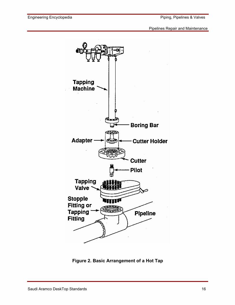
Figure 2 illustrates the basic arrangement for making a hot tap and illustrates the primary components. These are described below:
Stopple or tapping fitting: A specially designed branch connection that is welded to the pipeline.
Tapping Valve: A full-bore valve that permits closing off the branch connection after the hot tap has been completed. A new pipe section can be bolted on to the flanged valve as required after the hot tap has been completed.
Pilot: A relatively small-diameter drill that is attached to the cutter and makes the initial cut into the pipeline. The pilot also contains the mechanism that will retain the coupon after the cut has been made.
Cutter: The drill bit that makes the required diameter hole into the pipeline.
Cutter Holder: The end of the boring bar to which the cutter is attached. This arrangement permits the attachment of different sized cutters to the boring bar.
Engineering Encyclopedia Piping, Pipelines & Valves
Pipelines Repair and Maintenance
Saudi Aramco DeskTop Standards 15
Boring Bar: The shaft that is attached to the tapping machine, which transmits the applied force and rotation from the machine to make the cut.
Tapping Machine: The powered or hand-operated unit that performs the hot tap operation.
Adapter: A fitting, which provides a flanged interface between the standard flange diameter at the bottom of the hot-tap machine and the required flange diameter of the new branch connection.
Engineering Encyclopedia Piping, Pipelines & Valves
Pipelines Repair and Maintenance
Saudi Aramco DeskTop Standards 16
Figure 2. Basic Arrangement of a Hot Tap
Engineering Encyclopedia Piping, Pipelines & Valves
Pipelines Repair and Maintenance
Saudi Aramco DeskTop Standards 17
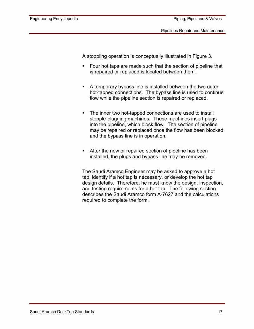
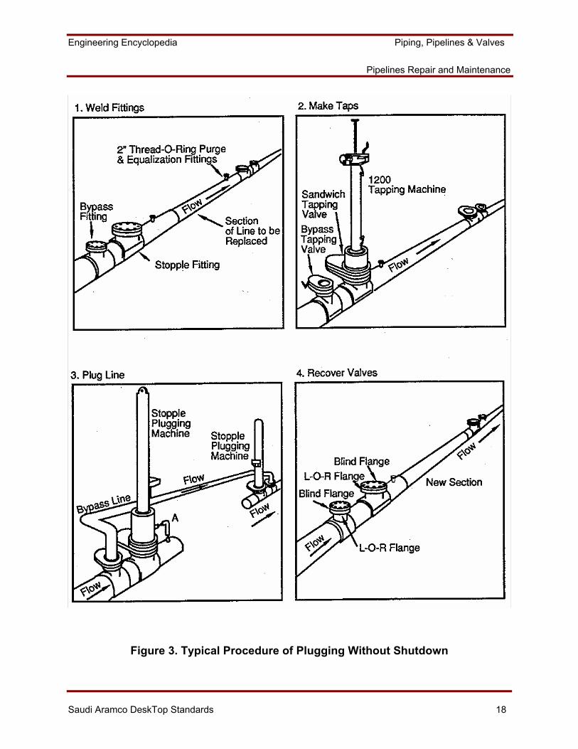
A stoppling operation is conceptually illustrated in Figure 3.
Four hot taps are made such that the section of pipeline that is repaired or replaced is located between them.
A temporary bypass line is installed between the two outer hot-tapped connections. The bypass line is used to continue flow while the pipeline section is repaired or replaced.
The inner two hot-tapped connections are used to install stopple-plugging machines. These machines insert plugs into the pipeline, which block flow. The section of pipeline may be repaired or replaced once the flow has been blocked and the bypass line is in operation.
After the new or repaired section of pipeline has been installed, the plugs and bypass line may be removed.
The Saudi Aramco Engineer may be asked to approve a hot tap, identify if a hot tap is necessary, or develop the hot tap design details. Therefore, he must know the design, inspection, and testing requirements for a hot tap. The following section describes the Saudi Aramco form A-7627 and the calculations required to complete the form.
Engineering Encyclopedia Piping, Pipelines & Valves
Pipelines Repair and Maintenance
Saudi Aramco DeskTop Standards 18
Figure 3. Typical Procedure of Plugging Without Shutdown

Engineering Encyclopedia Piping, Pipelines & Valves
Pipelines Repair and Maintenance
Saudi Aramco DeskTop Standards 19
Preparation Requirements for Hot Taps (Form SA-7627-ENG)
There are several requirements prior conducting the hot tap. SAEP-311 and SAES-L-052 describe these requirements in details. In this section, we will summarize the inspection and the testing requirements needed to complete the form SA-7627-ENG.
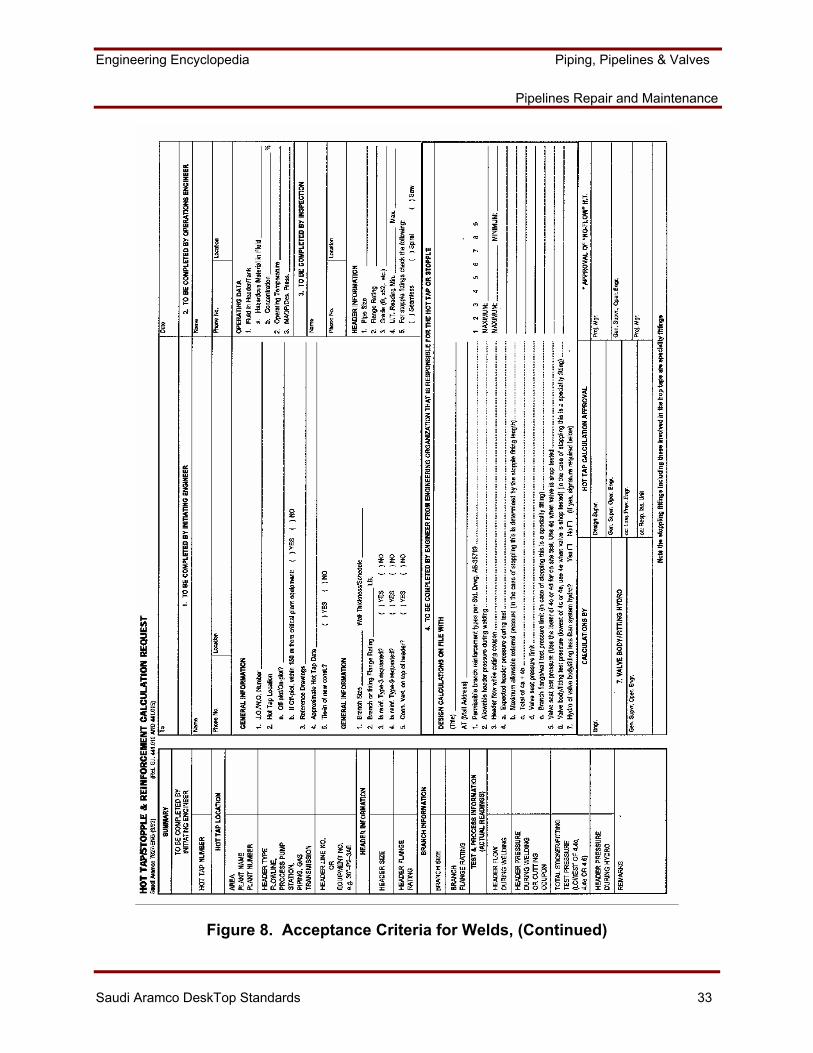
Form SA-7627 as shown in Table 1, consists of four sections and a summary section. These shall be completed in following sequence and by the organization identified:
Table 1. Form SA-7627
Form Section # Person /Organization
Summery (Hot Tap Location, Header Info, and Branch Info)
Initiating Engineer
Section One
Initiating Engineer
Section Two Operations Engineer
Section Three Responsible Inspection Unit
Section four Operations Eng. Div.
Summery (Test & Process Info)
Initiating Engineer
Engineering Encyclopedia Piping, Pipelines & Valves
Pipelines Repair and Maintenance
Saudi Aramco DeskTop Standards 20
Inspection Requirements
The Inspection Unit shall be responsible for the following:
Inspect and determine the minimum pipe wall thickness at the tie-in weld areas by using continuous UT (Ultrasonic Testing) examination. These areas shall include weld areas, and 50 mm (2 in.) on each side of them. The measured thickness must be less than the pipeline minimum wall thickness and no less than 5 mm (0.2 in).
Identify laminations or cracks in the area.
Approve welding procedure.
Inspect connection before and during installation for compliance with specification.
Confirm that hydrostatic test pressure conforms to that specified.
Witness and approve the hydrostatic test of equipment and connection.
Confirm that the connection is opened, drained, and vented after completing hydrostatic test.
Testing Requirements
The engineer responsible for testing must apply the following test requirements:
• The hot-tap machine must be periodically pressure tested based on SAEP-311 requirements.
• The hot-tap valve shall be pressure tested prior to installation.
Engineering Encyclopedia Piping, Pipelines & Valves
Pipelines Repair and Maintenance
Saudi Aramco DeskTop Standards 21
• Pressure test the branch-to-pipe weld, and then pressure test the final branch assembly.
• The reinforcing pad of a welded branch shall be tested with air at 173 kPa (25 psig) through a tapped vent hole. The test pressure shall be then reduced to 21-35 kPa for a tightness test using a soap solution.
• The pressure for the test of the hot-tap connection shall be 1.5 times the system design pressure (1.25 times for cross-country pipelines), however, not to exceed the following:
Maximum test pressure of branch connection flange or wall thickness.
The minimum pressure in the pipe or vessel being hot tapped, while the test is in progress, plus a calculated differential pressure. The differential pressure shall be 1.25 times the allowable external pressure calculated per the ASME Code Section VIII Division 1. The length, L, which is used in this calculation, shall be the total length of a split tee, or the inside diameter of the welded nozzle, based on the actual design detail used.
The test pressure of the hot-tap connection may be lower than the original hydrostatic test pressure. This is acceptable since the purpose of the test is to provide some assurance of the integrity of the connection weld, not a proof test of the weld. The system being tapped need not be derated if a lower test pressure is used at a hot-tapped connection.
Calculations
All design calculations required for hot tap or stopple are listed section 4 of SA-7672-ENG form. Other sections do not require any calculations. Followings are all formulas required for each item of section 4 of SA-7672. Some of these formulas are already covered in the previous modules.
Maximum Allowable Header Pressure During Welding (Item 2 of section 4).
Engineering Encyclopedia Piping, Pipelines & Valves
Pipelines Repair and Maintenance
Saudi Aramco DeskTop Standards 22
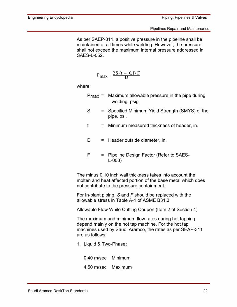
As per SAEP-311, a positive pressure in the pipeline shall be maintained at all times while welding. However, the pressure shall not exceed the maximum internal pressure addressed in SAES-L-052.
Pmax = 2S (t − 0.1) F
D
where:
Pmax = Maximum allowable pressure in the pipe during welding, psig.
S = Specified Minimum Yield Strength (SMYS) of the pipe, psi.
t = Minimum measured thickness of header, in.
D = Header outside diameter, in.
F = Pipeline Design Factor (Refer to SAES- L-003)
The minus 0.10 inch wall thickness takes into account the molten and heat affected portion of the base metal which does not contribute to the pressure containment.
For In-plant piping, S and F should be replaced with the allowable stress in Table A-1 of ASME B31.3.
Allowable Flow While Cutting Coupon (Item 2 of Section 4)
The maximum and minimum flow rates during hot tapping depend mainly on the hot tap machine. For the hot tap machines used by Saudi Aramco, the rates as per SEAP-311 are as follows:
1. Liquid & Two-Phase :
0.40 m/sec Minimum
4.50 m/sec Maximum
Engineering Encyclopedia Piping, Pipelines & Valves
Pipelines Repair and Maintenance
Saudi Aramco DeskTop Standards 23
2. Gas:
0.40 m/sec Minimum
9.10 m/sec Maximum
However, if the branch connection size is less than 50% of the size of the line being hot tapped, then the minimum values do not apply but a positive flow shall be maintained.
Maximum Allowable External Pressure (Item 4a of Section 4)
The maximum allowable external pressure for the header is calculated to ensure that the pipeline can withstand the branch connection hydro test pressure. As discussed in the previous modules, the allowable external pressure is calculated based on ASME SEC VIII D1, Paragraph UG-28. The differential pressure shall be 1.25 times the allowable external pressure as indicated in the following formula:
Pa = 1.25 (4B)/(3 (D/t))
As per ASME- XIII, Div. 1, the followings parameters are needed to calculate the differential pressure:
D = Outside Header Diameter
T = Minimum U. T. Reading of The Header
L = Branch Inside Diameter or Length of the Split Tee
To find B you need: D/t, L/D
From ASME-II, Figure G, A can be found
From ASME-II, Figure CS-1,2,3 B Can be found
If the value of A is falling to the left of the applicable temperature-line in figure UCS-28.2, the following formula should be used:
Pa = 1.25 (2 AE)/( 3 (D/t))
Where:
E = Modulus of Elasticity of the Materiel.
Engineering Encyclopedia Piping, Pipelines & Valves
Pipelines Repair and Maintenance
Saudi Aramco DeskTop Standards 24
PIPELINES REPAIR METHODS
Welded pipe sleeves are the most common repair method used in Saudi Aramco. Other repair methods such as Welded Pipe Patches and Weld Build are also used. Each repair method should be selected based on the defect type. However, it must be economically justified in terms of pipeline integrity or production loss since some the pipeline repair methods are more expensive than others.
All pipelines repairs are not acceptable for in plant piping on permanent basis. They are used on a temporary basis and replaced with new pipe during the shutdown.
Welded Pipe Patches
Welded pipe patches may be used to repair nonleaking sections of pipe that have experienced excessive external thinning. Patches used to repair minimum wall thickness violations shall have full sized fillet welds that blend in smoothly with the pipe surface. Refer to Standard Drawing AE-036265. On the other hand, patches used to repair external corrosion shall have a minimum 4.8 mm fillet weld around the entire circumference. Refer to Standard Drawing AE-0036261.
Weld Build-up
Weld build-up may be used to repair small areas of pipe or fittings that have experienced excessive external corrosion, nicks, scratches, gouges or grinding. Refer to Standard Drawing AE-036263 and SAEP-310 for the weld requirements and repair area limitations.
Engineering Encyclopedia Piping, Pipelines & Valves
Pipelines Repair and Maintenance
Saudi Aramco DeskTop Standards 25
Repair Sleeves
There are two major groups of repair sleeves:
Pressure Containing Repair Sleeves.
These types of repair sleeves are used to withstand internal pressure. They may be used for external or internal defects such as pinhole leak. They may be also used to protect the line from damaging stresses, such as dents, gouges, or scratches. The carbon steel sleeve is pneumatically tested. Examples of pressure containing sleeves:
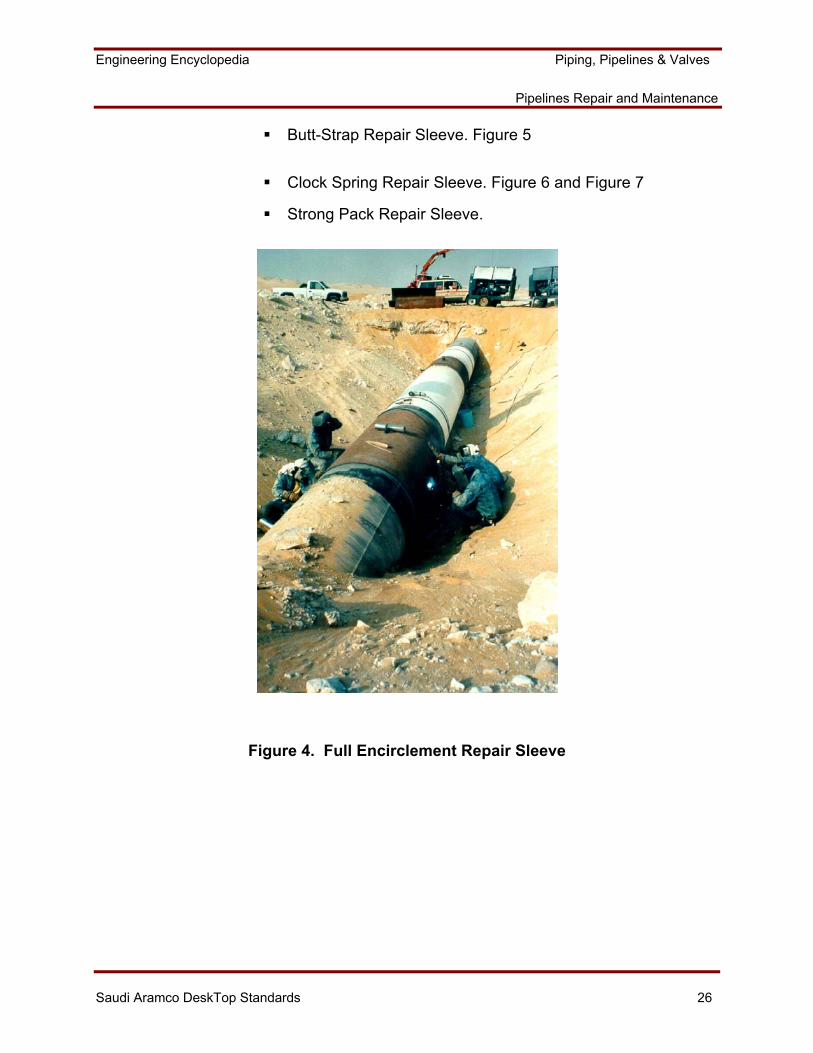
Fully Welded Encirclement Repair Sleeves (see Figure 4).
Epoxy Filled Sleeve (British Gas).
Plidco Sleeves. Refer to SAEP-314, SAEP-310 and Plidco catalog.
When repairing leakage with pressure containing sleeve, it must be first stopped or diverted before welding the repair sleeve to the pipe. The leak may be stopped by using a suitable wooden or steel plug. Refer to Standard Drawing AE-036833.
Non Pressure Containing repair Sleeves
These are used for non-leaking pipelines suffering minimum wall thickness violations due to external corrosion such as pitting. There are intended to add strength to the pipeline. They require surface preparations such as sand blasting and do not require pneumatic test. Examples of non-pressure containing repair sleeve:
Engineering Encyclopedia Piping, Pipelines & Valves
Pipelines Repair and Maintenance
Saudi Aramco DeskTop Standards 26
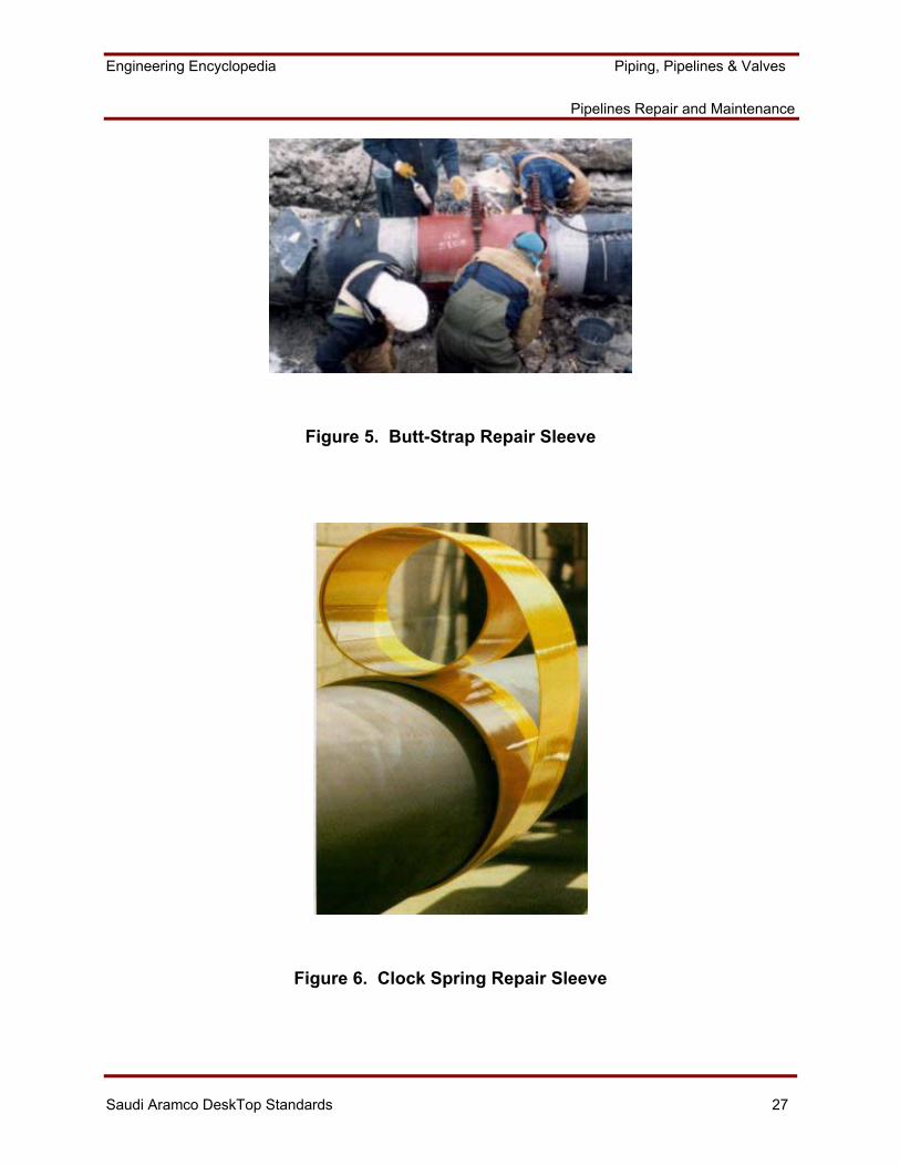
Butt-Strap Repair Sleeve. Figure 5
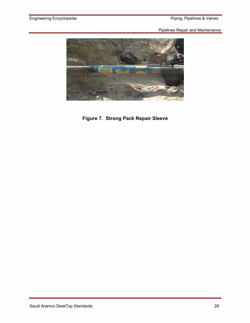
Clock Spring Repair Sleeve. Figure 6 and Figure 7
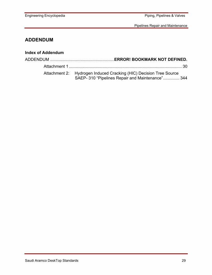
Strong Pack Repair Sleeve.
Figure 4. Full Encirclement Repair Sleeve
Engineering Encyclopedia Piping, Pipelines & Valves
Pipelines Repair and Maintenance
Saudi Aramco DeskTop Standards 27
Figure 5. Butt-Strap Repair Sleeve
Figure 6. Clock Spring Repair Sleeve
Engineering Encyclopedia Piping, Pipelines & Valves
Pipelines Repair and Maintenance
Saudi Aramco DeskTop Standards 28
Figure 7. Strong Pack Repair Sleeve
Engineering Encyclopedia Piping, Pipelines & Valves
Pipelines Repair and Maintenance
Saudi Aramco DeskTop Standards 29
ADDENDUM
Index of Addendum ADDENDUM .......................................................ERROR! BOOKMARK NOT DEFINED.
Attachment 1 ................................................................................................. 30
Attachment 2: Hydrogen Induced Cracking (HIC) Decision Tree Source SAEP- 310 “Pipelines Repair and Maintenance”.............. 344
Engineering Encyclopedia Piping, Pipelines & Valves
Pipelines Repair and Maintenance
Saudi Aramco DeskTop Standards 30
Attachment 1
Engineering Encyclopedia Piping, Pipelines & Valves
Pipelines Repair and Maintenance
Saudi Aramco DeskTop Standards 31
Figure 8. Acceptance Criteria for Welds
Engineering Encyclopedia Piping, Pipelines & Valves
Pipelines Repair and Maintenance
Saudi Aramco DeskTop Standards 32
Figure 8. Acceptance Criteria for Welds,(Continued)
Engineering Encyclopedia Piping, Pipelines & Valves
Pipelines Repair and Maintenance
Saudi Aramco DeskTop Standards 33
Figure 8. Acceptance Criteria for Welds, (Continued)
Engineering Encyclopedia Piping, Pipelines & Valves
Pipelines Repair and Maintenance
Saudi Aramco DeskTop Standards 34
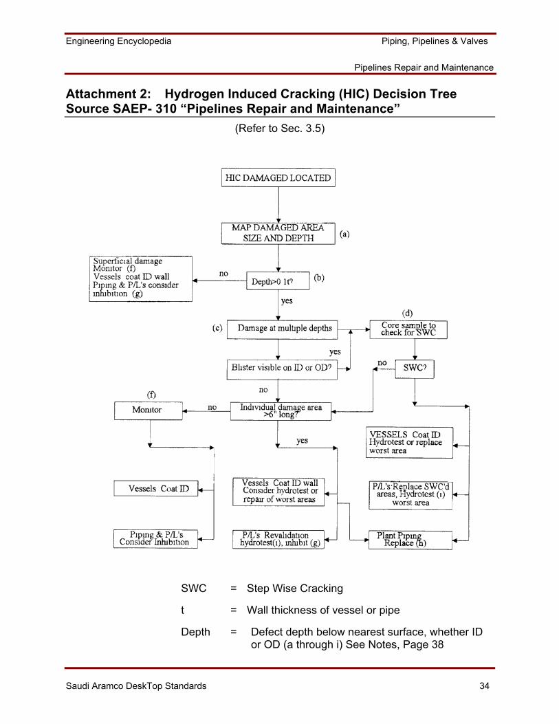
Attachment 2: Hydrogen Induced Cracking (HIC) Decision Tree Source SAEP- 310 “Pipelines Repair and Maintenance”
(Refer to Sec. 3.5)
SWC = Step Wise Cracking
t = Wall thickness of vessel or pipe
Depth = Defect depth below nearest surface, whether ID or OD (a through i) See Notes, Page 38
Engineering Encyclopedia Piping, Pipelines & Valves
Pipelines Repair and Maintenance
Saudi Aramco DeskTop Standards 35
Hydrogen Induced Cracking (HIC) Decision Tree (Continued)
A) Once suspected hydrogen induced cracking (HIC) damage is located, it should be surveyed to determine the size and shape of the damaged area, whether the suspected HIC occurs as small isolated spots or nearly continuous fields, and the depths at which the suspected HIC is detected. Such surveys are normally conducted using ultrasonic examination.
b) Before assuming that the depth of a defect is less than 0.1 t, the area should be ultrasonically examined from both inside and outside surfaces, when possible, to insure that additional areas of HIC at different depths are not masked from detection by the near-surface defect.
c) Hydrogen blistering at mid-wall is a common manifestation of HIC. Such mid-wall blistering produces little strength loss unless accompanied by Step-Wise Cracking (SWC), in which blisters are several different depths link up at shear steps.
d) Contact the CSD/CCD/Materials Engineering Unit, for appropriate sample locations and for the metallographic examination to detect SWC.
e) High, sharply crowned blisters may have SWC around the blister periphery, which may be difficult to detect with ultrasonic examination. Sample such areas as in note (d) to check for SWC.
f) Monitoring of items with HIC normally involves regular and frequent ultrasonic examination of the damaged area to determine whether the HIC is growing or not. If the HIC continues to grow, periodic reassessment through the decision tree will be necessary. Hydrogen evolution monitoring is used to check the inhibitor effectiveness in pipelines. In general, items with a history of HIC should also be internally inspected more frequently than similar equipment of HIC.
g) The inhibitor injection rates required for arresting HIC are much higher than those normally used for suppressing general corrosion. Contact the CSD/CCD/Corrosion Studies Group, for specific application details.
h) It is assumed that arresting further HIC in plant piping, which cannot be coated in place and may be difficult to inhibit effectively, may be uncertain and thus replacement will eventually be required. The urgency of replacement will vary widely depending on operational circumstances and the extent of HIC damage. Consult the CSD/CCD/MEU.
i) If blistering is extensive, of if SWC is observed, the residual strength of the item is best determined by a hydrostatic test at a nominal stress of 90% of yield. After revalidation hydrotesting, vessels or cross-country pipelines with HIC may be continued in service provided further HIC growth is arrested with coatings, inhibitors or both. Intensive monitoring may be required.