
METSIM-Brochure2-2009.pdf
40
Transcript of METSIM-Brochure2-2009.pdf


METSIM ®For Windows
The World’s Premier PC Simulation Package
for complex Metallurgical & Chemical Engineering Processes.
BROCHURE CONTENTS
- Introduction................................................................................................................................................3
- Model Planning..........................................................................................................................................5
- Model Flowsheet Development & Key Definitions............................................................................6
- Files & Directories....................................................................................................................................7
- Components................................................................................................................................................8
- Drop Down Menus.....................................................................................................................................9
- Unit Operations Overview & Overview of Some Generic Unit Operations...............................1 2
- Unit Operations - General, Mining, Materials Handling & Comminution................................1 3
- Unit Operations - Benefiticiation, Hydrometallurgy, Pryometallurgy & Gas Handling........1 5
- Dynamic Simulation Unit Operations & Costing Module................................................................1 5
- Operating Cost Report...........................................................................................................................1 6
- Stream Data.............................................................................................................................................1 7
- Reactions...................................................................................................................................................2 0
- Process Controls......................................................................................................................................2 1
- METSIM Mechanics...............................................................................................................................2 3
- APL .............................................................................................................................................................2 4
- Value Functions Overview....................................................................................................................2 5
- Value Functions.......................................................................................................................................2 6
- METSIM Flowsheets..............................................................................................................................3 1
Mr Kevin Charlesworth, DirectorKevin Charlesworth ConsultingAustralian and AsianAgent For METSIMPO Box 2021Port Macquarie, NSW 2444AustraliaTel & Fax: 612) 6583 3274Email: [email protected] Page: http://members.ozemail.com.au/~ozmetsim/
METSIM is Developed by:PROWAREMr . John BartlettTel: (1-520)-299-7834Fax: (1-520)-299-8009E-Mail: [email protected]: http://www.metsim.com

In t roduct ion
The basis for analysis of all chemical and metallurgical processes is the mass and energy balance. Plantdesign, capital costs, and technical evaluations are all dependent on such calculations. METSIM is ageneral-purpose process simulation system designed to assist the engineer in performing mass and energybalances of complex processes. METSIM uses an assortment of computational methods to effect an optimumcombination of complexity, user time, and computer resources usage.
METSIM originated as a metallurgical process simulation program, written to perform mass balancesaround the major unit operations of complex process flowsheets. Application of the program proved sosuccessful that it was expanded to include detailed heat balances, chemistry, process controls, equipmentsizing, cost estimation, and process analysis. The unique nature of the programming language, APL,allows modification and expansion of the system with minimum effort and permits the incorporation ofcontinuing technological innovations in process simulation.
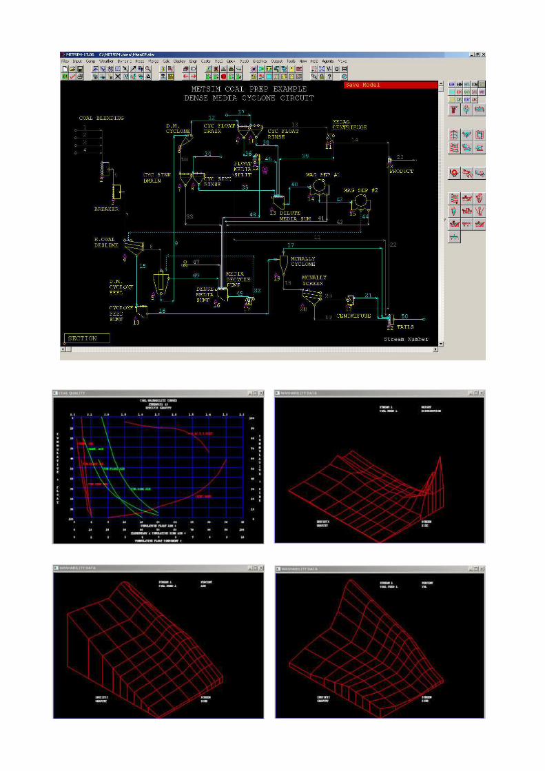
Many diverse processes, including chloride leaching of molybdenum concentrates, hydrochloric acid leachingof alumina clays, gold cyanidation / precipitation, roasting and flash smelting of copper concentrates, SAGmilling of various ore types, acid and carbonate leaching of uranium and vanadium ores, heavy media coalpreparation plants, base metal smelting, and gold and copper heap leaching, have been modeled withMETSIM .
METSIM can perform mass and energy balance calculations for:
1. Process feasibility studies.
2. Alternative flowsheet evaluations.
3. Pilot plant data evaluation.
4. Full scale plant design calculations.
5. Operating plant improvement studies.
6. Actual plant operations.
Some advantages of using METSIM are:
1. Computer simulation is less costly than operating a pilot plant.
2. METSIM facilities extrapolation and scale-up of process options.
3. METSIM requires the engineer to develop a detailed understanding of the process and provides aformat for evaluating process design criteria.
4. METSIM allows evaluation of operating techniques and anticipation of potential problems.
The complexity of METSIM models created is dependent on the purpose of the computer simulation andthe ingenuity of the engineer. It is suggested that users become familiar with the program through the online-help system before attempting to build a model. Only in this way can the user take full advantage ofall the unique attributes of the METSIM program. This on-line help is organized such that the user isfirst acquainted with the basic components of the system and the procedures to be followed to get theprogram running. It also provides the detailed data requirements of the various components and themechanics of entering process model data in the METSIM program.
METSIM provides the power of the largest computers with the complexity of advanced engineeringmathematics. METSIM was designed to take full advantage of the work space characteristics, interactivecapabilities and functional power of APL. The need for complicated job control language, file handling,text editing, and debugging programs has been eliminated.
3

METSIM performs mass and energy balances for chemical processes using the sequential modular approach.This method is used because of its elegance and amenability to simplify divers and complex flowsheets.METSIM can easily be expanded to encompass new processes and techniques. A major advantage of thisapproach is that intermediate results may be obtained from any stage of the process in an intelligibleform. This attribute of METSIM is invaluable when attempting to detect possible modeling or specificationerrors.
In conformance with the sequential modular approach, METSIM comprises modules containing subsetsof equations describing the design specifications and performance characteristics for each process step.The system solves the equation subset for each module, allowing for an individual analysis of each unitoperation in the flowsheet. Given data on design variables and input stream composition, each modulecalculates all of the output stream variables, which can then be used as input stream values for the nextprocess step. The modules access data on all independent stream variables from the data arrays containedwithin the APL global workspace. Additional input data required to solve the equations in each moduleare requested by the program and are stored as global variables. The user may supply actual data obtainedfrom operating or pilot plants, from similar processes, or from estimates supplied by the engineer.
Unlike several process simulation programs currently in use within the chemical process industry, METSIMeliminates the need for user involvement in recycle stream tearing. METSIM employs a technique wherebythe user is required only to provide initial estimates of the recycle stream content of critical processstreams. Multiple stream numbers are not required and METSIM determines which streams are to betorn. Rapid recycle stream convergence is assured by using the Wegstein convergence accelerator. Thistechnique almost always results in recycle stream convergence in less iteration than the direct substitutionmethod.
METSIM ’s flexibility is further enhanced by the use of feedforward and feedback controllers for processadjustment and control. Since the dynamic behavior of METSIM ’s controllers is similar to that of processcontrols in operating plants, unstable control strategies can often be located during the modeling stage,avoiding costly field modification and retrofit.
The successful application of the METSIM system of programs involves more than simply entering fixeddata on standardized input sheets. Due to the wide variation in chemical and mineral processing techniques,available data, process criteria, and output data requirements, the development of process models is asmuch an art as it is a science. METSIM is not a panacea for the engineer; it supplements not replaces,sound engineering practices and judgment. The user must be familiar with process engineering mass andenergy balance calculations. Familiarity with mathematical modeling, numerical analysis, and processcontrol is most helpful when modeling complex processes.
4

Model Planning
The old adage ‘No one planned to fail. They failed to plan‘, applies to process modeling as any othercomplex activity. Modeling is not a trivial task. METSIM is a powerful tool, which can easily be abused bynot ‘getting it right’ from the beginning. The following sequence is strongly recommended from experiencewith many flowsheeting projects. Whilst it is recognized that information, especially about new processes,will be incomplete, this sequence should be followed as closely as possible. Due to the wide variation inmetallurgical and chemical processes, purposes of models, and availability of data, individual judgementmust be made as to the amount of time and detail given to each step.
1 Assemble all available information before beginning.
2 Sketch a process flowsheet with all unit operations and streams present.
3 Make a list of all phases present and list all components in each phase.
4 Load METSIM , Initialize the model to zero all data.
5 Use the 'Model Parameters' Task Bar Button to set the major switches and select the units of mass andtime.
6 Select the components from the database ‘DBAS Component Database‘ and edit component data ‘ICOMEdit Components‘.
7 Select appropriate METSIM unit operation modules listed under the screen object buttons, andcompile the data required to execute each.
8 Write out chemical components and reactions in each unit operation.
9 Build the flowsheet using the Screen Interface palette entering all unit operations and streamssection by section.
1 0 Add unit operation data, equipment sizes, and separation parameters, and add unit operationchemistry and heat balance data.
1 1 Provide precise flowrates and compositions for all input and estimates for recycle streams.
1 2 Enter stream names and input stream flowrates and composition.
1 3 Calculate flowsheet and check results to verify input and mechanisms, and debug the model.
1 4 Add process controls to adjust parameters to meet design criteria.
1 5 Add detailed algorithms, minor streams, and trace elements to completion.
1 6 Execute main calculation program and debug the model.
1 7 Generate the required output reports.
1 8 Provide a detailed process description, and track revisions of the model underneath.
5

Model Flowsheet Development
The developed flowsheet should be as complete as available data permit and structured to produce levelsof accuracy desired in the final results. Input data can be readily revised as the flowsheet evolves fromgeneral to detailed, but it is desirable to make allowances for the addition of flowstreams and unit operationsas complexity increases. One should examine the flowsheet carefully for omission of any streams. All massentering or leaving the process must be associated with a process stream. Typical omissions included pumpgland water, evaporative losses, open tank off gases, and infiltration air. These types of flows are oftenomitted in general process evaluations but should be included in detailed design calculations.
METSIM unit operation modules should be defined at each point where one or more of the followingconditions exist.
1 One or more streams join to form a new stream.
2 One or more streams split into two or more streams.
3 One or more streams undergo a chemical reaction, phase change, temperature change, particle sizechange, or any physical changes resulting in the formation of a new stream of different chemical or physicalproperties.
The user need not be concerned with the precise nature of the unit operation module at this time. Generallyunit operations are numbered sequentially following the path of process flow. METSIM allows addition ofunit operations through the screen interface and changes in the sequences of calculations through theroutine ‘ IFLS Use "ONLY" to Rearrange Flowsheet “. Unit operations and their data are renumberedautomatically.
Unit operations modules forming recycle loops should be listed consecutively. Flowsheets having multipleand / or nested recycle operations complicate application of this guideline; however, experience gainedthrough repeated use of the system will enable the user to assign unit operation numbers to maximizesystem efficiently.
6
Key Definitions
To prevent misunderstanding and confusion the following key definition should be noted:
COMPONENTS - mass balance entities such as molecular compounds, pure elements, pseudocompounds, ions, etc.
PHASES - groups of components, which do not physically mix.
STREAMS - material flows of components between unit operations.
UNIT OPERATIONS - process units where streams merge, interact and separate.
MODULES - unit operation programs or groups of programs.
MODELS - process flowsheets composed of unit operations and streams.
CONTROLLERS - programs, which adjust variables to meet process criteria.
MASS BALANCE - calculated or simulated flows into and out of a process.
MA TERIAL BALANCE - measured plant data adjusted to give a perfect mass balance.

Files and Directories
When METSIM is installed, a METSIM directory is created containing the following files andsubdirectories.
METSIM DIRECT ORY
File Type DescriptionInstal l LOG File log of selections and installationMETSIM Adf APL Definition FileMETSIM Application APL runtime METSIM programMETSIM Help File All METSIM online HELPMETSIM Icon METSIM screen iconsMETSIM W3 METSIM APL Program filesUnits Application Uninstall program for METSIMUnwise Application Uninstall program for Wise
METSIM DIRECT ORY SUBDIRECTORIES
DBF contains about 100 thermodynamic database files as METDBxx.SF, where xx is the elementsymbol. Components are stored in file with the highest element number first.
Fnc User Created APL Calculation Routines
Icons contains all METSIM screen objects Icons
MET contains the following METSIM operating files:
Metmacw.sfw File containing Licensee configurationMettab.sf File containing METSIM tabulated dataMetwini.sf METSIM windows initiation fileStemp METSIM Security Device files and programs
MEX contains the following examples of flowsheet models:
MWXAP Sulphuric Acid PlantMWXCC SAG Mill/Ball Mill Comminution with CostingMWXUCIP CIP/CIL Unit OperationMWXCuHL Copper Heap LeachMWXDPS Dynamic Pierce Smith ConverterMWXDTNK Dynamic Tank with XCEL DDE ExchangeMWXFC Lead/Zinc FlotationMWXFF Flash Furnace SmeltingMWXHYL Direct Iron Ore Reduction using HYL ProcessMWXNG Natural Gas Burner FEMMWXpHCTL pH Control DemonstrationMWXSMLT Smelter with SectionsMWXSXEW Solvent Extraction and EletrowinningMWXAUT Autoclave
Stemp Contains APL Windows 95, 98 and NT subdirectories, and application S file setup
XXX additional sub-directories can be created to store model files in. The pointer to themodel sub-directory may be changed to any directory on any drive. It should be notedthat these sub-directories should not have further sub-directories, or the file handlingwill indicate an error.
7

8
Components
METSIM carries out mass balance calculations by tracking material flows, which are made up of amixture of components. These are the chemical species, such as pure chemicals, minerals or elements,and can exist in one or more of eight phases. The phases are identified by their phase number. Prior tousing any of the component input routines, first prepare a comprehensive list of the components, whichit is anticipated will appear in the flowsheet. Components are assigned to the phases in which they arepresent.
The phases are:
Component P h a s e P h a s eGroups Variable Number Types of components
Solid Components SC Includes SI & SOSolid Inorganic SI 1 Minerals, SaltsSolid Organic SO 2 Coal, Resin, CarbonFluid Components FC Includes LC & GCLiquid Components LC Includes LI, LO, M1, M2 & M3Liquids Inorganic LI 3 Water, Acids, Dissolved SaltsLiquid Organic LO 4 Fuel, Kerosene, OrganicsMolten 1 M1 5 Molten Metals, SpeissMolten 2 M2 6 Molten Sulfides, HalidesMolten 3 M3 7 Molten Oxides, SlagsGaseous components GC 8 Air, Gaseous, Metal Vapors
Components can be entered into a flowsheet model through one of three methods: -
1 - METSIM Database stored in the METSIM DBF sub-directory.Using the routine ‘ DBAS Component Database ‘
2 - User Database, stored in the file METDBUS.SF in the DBF sub-directory. This file is automaticallyloaded with the METSIM database. The file is created and edited via the routine ‘IUSR Edit UserDatabase ‘.
3 – Created directly through the component input/edit routine ‘ ICOM Edit Components’.
The process model components are saved with the model in the model storage file Filename.sfw, andautomatically reloaded when the model file is re-loaded into the workspace. This ensures continuity ofdata.
Model components can be saved into the User Database file using the routine ‘ IUS2 Add Model Compto database’.

Drop Down Menus
The following drop down menus are located along the top of the screen and contain programs used tocreate, build, develop, analyze and save flowsheet models i.e.:
F i les Handling files i.e. saving and retrieving Models
S e t u p Flowsheet palette setup parameters for fonts, colors and objects
I n p u t Definition of flowsheet parameters, case, flow matrix, stream qualities and controls
Components Selection and definition of flowsheet components
Weather Input, calculation plotting and output routines for weather patterns for heap leachand solar evaporation flowsheets data
H e a p All Routines associated with Heap Leach Option -Input, parameter definition,checking, calculation and outputs.
Merge Routines for merging models and model sections
Calc Menu for calculating and checking routines
Disp lay Standard and Custom display routines
Costs Input and output operating cost data routines
Graphics Graphics setup and output routines
EquipLis t Design, Editing and Output of Equipment Lists and Equipment Specifications
Outpu t Standard output reports
Tools Miscellaneous programs for developing user objects, flowsheet evaluation, and savingand comparing flowsheet data.
N e w Menu for New Program Features
He lp METSIM Services, on line Help and Version Information
9

New Model - used to clear and initialize the METSIM workspace ready to build a model. On activation
it requests the user to confirm replacement of the existing model in memory.
Load Model - used to loading an existing flowsheet model file On activation it requests the user to
confirm replacement of the existing model in memory.
Save Model – used to save a flowsheet model directly to file. On activation it overwrites the old file data
with that in memory.
Print Flowsheet – used to print either the full flowsheet or selected sections.
Model Parameters – used to set flowsheet site, case, calculation setup and calculation limit parameters.
Error Checking – used to check out a flowsheet model immediately it has been loaded into the
workspace. The routine checks for: Stream errors.
Enlarge Drawing Size – enlarge the palette area, to expand the flowsheet
Reduce Drawing Size – reduce palette area, to fit the flowsheet into a smaller area.
Draw Flowsheet – to redraw or refresh the current flowsheet section.
Box Item To Move – used to box flowsheet areas which can be moved separately
Moves flowsheet drawing up the page.
Moves flowsheet drawing down the page.
Moves flowsheet drawing to the right on the page.
Moves flowsheet drawing to the left on the page.
Zoom In – used as an editing tool to enlarge the flowsheet.
Zoom Out used as an editing tool to reduce the flowsheet.
Center Flowsheet – to re-center the flowsheet on the screen.
Locate Stream – used to locate model streams.
Renumber a Stream – used to renumber a stream in the flowsheet.
Renumber Controls on this Page – used to renumber controllers in the current section.
Delete object – used to delete objects from the palette area.
Reverse Unit Op – used to reverse unit operation icons around the vertical axis
Change Object size – used to change the unit operation icon size.
Move object – used to move screen objects i.e. Stream routes, unit operation icons, controllers icons.
Move Text – used to move unit operation text descriptions on the screens.
Copy Object Data – used to copy data from one object to another.
Edit Object Data – used to edit data in unit operations, streams and controller data.
Weather Data – used to enter daily or monthly weather data
Ore Tonnes and Grade - used to enter ore types tonnes and grade data10

Contours - for use with the Heap Leaching Module.
Select Section – used to change between sections.
Follow Connecting Stream – used to check on flowsheet connections.
Page Up – used to page up through the sections of the flowsheet.
Page Down – used to page down through the sections of the flowsheet.
Calculate one unit operation – on activation any selected unit operation can be calculated.
Calculate Current Section – on activation all unit operations in the current section will be calculated.
Stop Execution - On activation will immediately stop flowsheet calculations. Used to abort calculations
as determined by the user.
Calculate Unit Operation Range – used to repeat calculations over the range determined by the user
through SCAL.
Calculate All Unit Operations – used to calculate the full flowsheet from any section. Useful for
situations where the user may wish to observe flowsheet changes during simulation.
Elements - used to display/select elements in the flowsheet.
Components - used to display/select components in the flowsheet.
Phases - used to display/select the phases in the current section.
Streams - used to display/select the streams in the current section.
Unit Operations - used to display the unit operations in the current section.
Instrumentation/Controlls - Used to display the instrumentation/controlls.
APL Keyboard - gives access to the APL Keyboard.
Maths Functions - Under development.
Value Functions - used to display/select Value Functions.
User Created Objects - used to display the list of User Created Objects.
Check Elemental Balance – used to calculate and display the section elemental balance.
Display Value Function for Streams - used to create and select value functions to replace stream
number on the flowsheet screen.
Display Section Spreadsheet - used to display data for all streams in the current section according to
the selections made via the DSDO Spreadsheet Items Standard, and DCSI Spreadsheet Items Custom
routines located in the Display drop down menu.
Plot Screen Analysis - used to plot screen analysis data for and selected stream(s).
Plot Dynamic Data - used to plot screen analysis data for and selected stream(s).
Display Instrument Spreadsheet - used to display a spreadsheet of Instrumentation Controls on current
section.
Lock Model for Security – used to setup model security options
DDE - used to display the list of DDE, Dynamic Data Exchange, links.
Tools Help - Under development.11

Unit Operations Overview
The basic calculation philosophy used in METSIM is to take the feed streams to a unit operation moduleand have a mechanism to handle the inputs and to output according to the module.
Most unit operation modules mix the feed streams then the mechanism is applied. That mechanism canbe preceded by chemical reactions or a phase change and if the result required is not achieved then themechanism or chemical reaction can be changed or a control applied as a feed forward or feedback loop.
It is possible therefore because of the structure of the program, to add chemistry to any unit operation andthen add controls to simulate any type of reactor without having a specific reactor model.
The calculation sequence for a typical unit operation is according to the following procedure:
- Retrieve unit operation data
- add all input streams component flows
- calculate reactions
- calculate unit operation mechanisms/routines
- separate the output streams according to the unit operation parameters
- save unit operation parameter data
If an output stream parameter is to be controlled, a feedback controller must be added to sample theoutput and adjust an input stream, a reaction extent or another unit operation parameter to achieve thedesired results.
Logic, PID, flowrate, Feedforward and density controllers may be used to adjust streams and parametersprior to calling the unit operation module.
Overview of some Generic Unit Operations
METSIM was originally developed to calculate mass and energy balances around any type of flowsheet ina timely manner. To facilitate this task several generic unit operation modules were used. Chemistry andheat balance data may be added to any of these units. They are:
SEC - Section used to add sections to a flowsheet.
STR - Stream used to add streams to a flowsheet
RCY - Recycled Str eam Links is used to facilitate convergence of multiple recycle streams in flowsheets.
MIX - Stream Mixer mixes all of the input streams and has a single output stream. Can be used tosimulate tanks, sumps, bins, mills, reactors, pumps and conveyors.
S L S - Solid/Liquid Separator simulates solid/liquid separations classifiers, thickeners, filters, ponds
S U B - Str eam Distributor allows streams to be closed for water balance, Controlled at different flowratesand totaled as for reagents.
S P C - Component Splitter allows components to be split differently in output streams. Can be used tosimulate flotation cells, gravity concentrators and recovery plants.
Phase Splitter allows phases to be split differently in output streams. Can be used to simulate solventextraction, CIP/CIL and furnaces.
Str eam Splitter is used to split one or more input streams into two to six output streams.
12

GENERAL Unit OperationsSectionSt reamRecycle Stream LinksStream MixerSloid/Liquid SeparatorStream DistributorComponent SplitterPhase SplitterStream SplitterSumpLaunderPump, CentrifugalPump, Positive DisplacementPump, VerticlePump, Metering
Pump, SumpPump, VacuumPipePipe ConnectionPipe HeaderTank - agitated tank with internal coils for heating or coolingTank - agitated tank with external jackets for heating or coolingTank - agitated storage tankTank - with internal coils for heating or coolingTank - with external jackets for heating or coolingTank - simulates a storage tankTank - decant tank for separating organic from aqueousTank - electrolyte or compartmented tankTank - process tank with agitationTank - storage tank without agitation or heating
MINING Unit OperationsORE from mineORE Tonnes & GradeShovelFront End LoaderHaul TruckTruck, ContainerTruck, Tanker
TrainDredgeClam ShellBargeShip, ContainerShip, Tanker
MA TERIALS HANDLING Unit OperationsStockpile, BlendedStockpile, by the LIFO, FIFO or MIXO methodStockpile, ReclaimStatic Screen BinScreen Grizzly, StaticScreen Grizzly, VibratingChute/HopperBinSiloHopperChute, Drop BoxSplitter, Flop GateConveyor, BeltConveyor, Chain/Drag
Conveyor, Bucket ElevatorConveyor, Apron FeederConveyor, PneumaticConveyor, ReclaimConveyor, ScrewConveyor, StackerConveyor, TransferAgglomeratorHeap Leach ColumnHeap Leach Test HeapHeap DumpHeap LeachHeap Leach ExtensionHeap Leach Drainage
COMMINUTION Unit OperationsCrusher, ConeCrusher, GyratoryCrusher, ImpactCrusher, JawCrusher, MMD SizerCrusher, RollHigh Pressure GrindingScreen, DMS/BananaScreen, DerrickScreen, VibratingScreen, TrommelMill, SAG
Mill, RodMill, BallMill, RollerRock ScrubberHydrocycloneClassifer, ScrewClassifer, HydroClassiferCentrifuge, DecantorCentrifuge, SeparatorCompactor
13

BENEFITICA TION Unit OperationsFlotation, ColumnFlotation, Jameson CellFlotation, CellGravity Separator, ConeGravity Separator, JigGravity Separator, MosleyGravity Separator, SpiralGravity Separator, TableGravity Separator, GeneralDry Magnetic SeparatorWet Magnetic Separator
Coal SpiralDense Media, BathDense Media, CycloneDense Media, DrumDense Media, SumpDense Media, GeneralDense Media, ScreenDense Media, VesselScreen DeslimingWater Only Cyclone
HYDROMET ALLURGY Unit OperationsCIP/CILColumn, Acitvated CarbonColumn, Ion ExchangeAbsorption ColumnHydrochloric Acid Stripper/AbsorberEquilibrium stageSolvent ExtractionSolvent Extraction, ReverseSolvent Extraction, ColumnEectrolytic CellEectrolytic Cell, MembraneElectro Refining CellElectrowinning CellFilter, Belt, CCWFilter, Belt, Parallel
Filter, CartridgeFilter, DrumFilter, LeafFilter, Dual MediaFilter, PressureFilter, LaroxThickener, RakeCountercurrent WashingWater SprayPond, Solar EvaporationPond, StoragePond, TailingsCrystallizerCrystallizer, VaporizerCrystallizer, Draft Tube Baffle
PYROMET ALLURGY Unit OperationsAutoclaveFlash SeparatorHeater, DirectFree Energy ReactorBurnerFluid Bed RoasterPacked Bed ReactorRotary Dryer, DirectRotary Dryer, IndirectFurnace, KilnFurnace, ElectricFurnace, Inco FlashFurnace, Top Submerged LanceFurnace, Outokumpu
Furnace, SettlerFurnace, UptakeFurnace, NorandaFurnace, El TenienteFurnace, Slag CleaningFurnace, ReverabatoryFurnace, Pierce SmithFurnace, HoodFurnace, AnodeLadles, Slag PotsWheel, CastingHYL BottomHYL Top
GAS HANDLING - STEAM Unit OperationsAbsorberAcid Plant ConverterSpray CoolerBaghouseDust Cleaning CycloneDust Collecting CycloneElectrostatic PrecipitatorDust, Collection PointVenturi ScrubberWet ScrubberBlowerFanFlue/StackGas CompressorGas Turbine
Joule-Thomson ValveHeat ExchangerHeat Exchanger, Steam CondenserHeat Exchanger, VerticleHeat Exchanger, GasSteam BoilerWaste Heat BoilerSteam TrapDaerator, DegasidierDesuperheaterSteam CompressorSteam TurbineBarometric CondenserSteam EjectorTower, Cooling
14

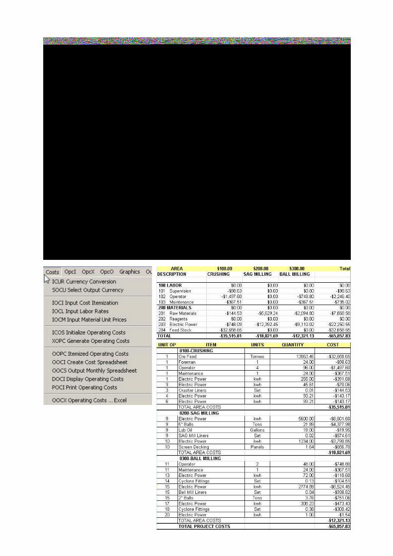
Costing Module
Operating costs are generated as a spreadsheet, with the cost items listed in rows and the costs incolumns. The spreadsheet is set up by defining the cost areas, then the items in each area with theircosts and then their types.
METSIM operating costs module is designed to enable the user to use the data generated by theflowsheet model to generate tables of operating costs. Costs are output in spreadsheet format and canbe itemized by flowsheet section, unit operation, and cost types. A series of routines are provided in amenu structure for input, calculation, editing and output. Operating costs can be determined, at anytime following the calculation of a model.
Costs can be incurred in different currencies and assembled in a single currency. The menu structure isdesigned to enable the user to input data by classification, such as labor, materials etc. for each unitoperation and plant section as appropriate, and output itemized costs for display, printing and export.
Dynamic Simulation Unit Operations
Dynamic modeling of flowsheets has been possible for many years, but METSIM has not been widelyemployed in that role. Other dynamic software simulation packages exist, such as speedup, which aretargeted more towards the chemicals industry. These packages use systems of differential and algebraicequations (DAEs) to describe unit operations, which, when linked together can describe sections of plantor entire flowsheets. Thus a user must have a great deal of knowledge as to what equations and modelsgovern the system they wish to model. METSIM offers a much simpler way to describe the flowsheet, andits solution is similar in nature to the numerical methods used to solve the systems of DAEs, if the chosentime step is short enough. For most flowsheets, the recommended time step is no longer than one-twentiethof the residence time of the material in the principal units.
There are two mechanisms for controlling the dynamic operation of a flowsheet: firstly, by providing aschedule; or secondly, by using logic controllers. Each mechanism has its merits, and we hope that futureversions of METSIM will incorporate a combination of the two.
Most straightforwardly, a schedule may be provided for the entire flowsheet, specifying what action istaken for each, fixed period of time. This works best for single batch operations, such as a Pierce-Smithconverter, when the charging, blowing, skimming and transfer periods last for a fixed time, and areaccompanied by a specific action. The most serious drawback with this mechanism is that it is not possibleto specify a logical condition determining the end of the period. For example, if a furnace is to be emptied,it is not possible to specify that its contents should be transferred at a specific rate until the furnace isempty. Instead, the rate must be calculated in order that the transfer takes a specific length of time. Aschedule may be constructed most easily from an existing plant: in this case, the actual operating parametersof the plant may be used, and the various unknown reaction rates and extents may be varied to ensure agood match. Having constrained the chemistry in this way, various hypothetical schedules may be testedagainst the original.
Alternatively, the entire operation of the plant may be dictated solely by logical if…then statements. It isa considerable undertaking to design logic controllers to describe the appropriate action for every state inwhich the flowsheet may exist. All the logical if conditions, obviously, are queried on every pass throughthe flowsheet (that is, on every time step), and each must evaluate either true or false, triggering anappropriate action. It is surprising how quickly such a scheme becomes unmanageable. This mechanismhas, however, been used successfully in at least one case.
Once the schedule or logic program has been completed, the other details of a dynamic simulation areexactly as for steady-state simulations, with the exception of feedback controllers. In a steady-statesimulation, the role played by feedback controllers is not strictly analogous to that played by feedbackcontrollers on a physical plant. These steady-state model feedback controllers are used primarily toautomatically calculate parameters (such as the mass of coal that must be burnt to dry a given quantity ofwet feed) that the modeler would otherwise have to calculate by repeated trial and error. This makescalculations of the effects of changing, for example, concentrate grade, far simpler and faster. In a dynamicmodel, however, (as in a real plant) the effects of changing a variable used previously in the flowsheet arenot felt until the next time step, and the controller must wait to determine whether the change made wassufficient, or whether further corrections are needed. The algorithms necessary to calculate the change tobe made to the controlled variable, from the error in the measured variable, are well established by themanufacturers of control equipment, and METSIM incorporates the two most popular. The tuningparameters (the proportional gain, etc.) needed for the model should therefore be the same as for the PIDcontroller in the real plant.
15

Operating Costs
CRUSHING SAG MILLING BALL MILLING Total
100 LABOR $0.00 $0.00 $0.00 $0.00
101 Supervision -$98.63 $0.00 $0.00 -$98.63
102 Operator -$1,497.60 $0.00 -$748.80 -$2,246.40
103 Maintenance -$367.51 $0.00 -$367.51 -$735.02
200 MATERIALS $0.00 $0.00 $0.00 $0.00
201 Raw Materials -$144.53 -$5,629.24 -$2,116.15 -$7,889.92
202 Reagents $0.00 $0.00 $0.00 $0.00
203 Electric Power -$461.74 -$12,392.45 -$7,819.85 -$20,674.05
204 Feed Stock -$32,658.65 $0.00 $0.00 -$32,658.65
TOTAL -$35,228.67 -$18,021.69 -$11,052.31 -$64,302.67
Detailed Operating Costs
UNIT OP ITEM UNITS QUANTITY COST
CRUSHING
1 Ore Feed Tonnes 13063.46 -$32,658.65
1 Foreman 1 24 -$98.63
1 Operator 4 96 -$1,497.60
1 Maintenance 1 24 -$367.51
1 Electric Power kwh 255 -$391.68
3 Electric Power kwh 45.612497 -$70.06
3 Crusher Liners Set 0.009635645 -$144.53
TOTAL AREA COSTS -$35,228.67
SAG MILLING
9 Electric Power kwh 5600.0034 -$8,601.61
9 5" Balls Tons 21.88991 -$4,377.98
9 Lub Oil Gallons 19 -$19.95
9 SAG Mill Liners Set 0.016417433 -$574.61
10 Electric Power kwh 1234 -$3,790.85
10 Screen Decking Panels 1.6417433 -$656.70
TOTAL AREA COSTS -$18,021.69
BALL MILLING
11 Operator 2 48 -$748.80
11 Maintenance 1 24 -$367.51
13 Electric Power kwh 206.23294 -$316.77
14 Cyclone Fittings Set 0.1306346 -$104.51
15 Electric Power kwh 2288.2964 -$7,029.65
15 Ball Mill Liners Set 0.037955407 -$948.89
15 2" Balls Tons 3.7955407 -$759.11
17 Electric Power kwh 308.22555 -$473.43
18 Cyclone Fittings Set 0.37955806 -$303.65
TOTAL AREA COSTS -$11,052.31
TOTAL PROJECT COSTS -$64,302.67
16

Stream Data
When activated the input data screen is displayed. A series of spreadsheets are displayed to allowstream data to be entered or edited as described below.
17
On exiting the stream data screen, the program returns to the palette and the edited stream number androute will change to the color of the predominant phase. For phase colors see ‘Select Object Colors‘.
The stream data input screen set out as follows.
Stream data is displayed along the top of the screen above a series of data entry spreadsheets.
The stream data is as follows:
The top line is used for text entry e.g. stream description. The second and third lines are for stream datavariables
Data Field Output Level Input Field Design Factor Input Field Maximum FlowInput Field Box Number Input Field Input Field Input Field Variables 1 2 3
Input Field for Output Level. Stream data is used to switch on/off the stream display. If the streamoutput level matches the display level as defined in DVAL Display Value Functions for Streams. Thestream data is displayed. This can be either the stream number, a stream value function or a streambox as defined in ISBX Design Stream Graphics Boxes.

Input Fields for Design Factor, Maximum Flow and Variables 1 2 and 3 are not used at present.
Input Filed for Box Number is used to replace data as defined in DVAL above by a graphics box as definedin ISBX. Box types are listed in ISBX.
Two direct Data entry fields located below for:
- the upper is for the stream name or description, initially defaults to flowsheet stream number.
- The lower is for the stream label, which is generally an alphanumeric P and I D flowsheet identifiers.Initially it defaults to flowsheet stream number.
Quick Access buttons are displayed to the left of the above. Only the buttons for the phases present inthe flowsheet are displayed.
Data Entry Spreadsheets for:
- Mass and volumetric flow rates, temperatures, pressures and operating time- Phase compositions by component- Phase elemental composition- Stream particle size distribution (which is activated through the SSA button)- Stream component size data (which is entered through the SSM button).- Stream washability or gravity separation data (which is entered through the WAS button).
The suggested method for entering stream data for the first time is to first enter the Mass for each phase,which will be in the units defined in the column header. Exact values are required for input streamsestimates for controlled input and recycle streams.
As each phase field is activated, components and elemental composition spreadsheets will appear, with thecomponents and their elements according to and in the order of the component list. If there are nocomponents listed for a phase no spreadsheet will appear. The phase buttons can also be used for dataentry. The mass flow of the phase is entered, by moving the mouse pointer to the relevant field PL. A blueborder highlights the field. Enter the flow PL. The first component listed for the phase will be allocated allof the material and its assay will change to 1 i.e. the phase is 100% of that component. Individual componentassays are entered as weight fractions or mole. fractions. As each assay is entered the phase compositionis recalculated and the assay of the first component will be adjusted to ensure the total assay is alwaysequal to 1 (100%).
Aqueous phase components are often referred can be entered as weight fraction or grams per liter (gpl).Similarly as with other phases the assay of the first component is balanced with each entry to maintainthe composition to 1.
Hence by choosing the first component in each phase to be either the inert or bulk material, the phaseassay is always balanced with a component, which will not cause major errors in chemistry through errorin input. In the aqueous water is always the first aqueous component as every other component is dissolvedin water.
The elements spreadsheet is designed similarly to that for components, with columns for weight fractionand gpl entries. In cases where elemental data is available, element composition can be entered. In thiscase METSIM will recalculate the component assay for that element composition. This is achieved bysetting up simultaneous equations. However where the chosen element is in several components, theremay be several solutions, METSIM will be unable to arrive at a solution. In this case the user will have tomake judgment, on which data is the best for the material.
The above procedure is repeated for each phase present in the stream.
For solid flows such as ores, the ore and adhering moisture flow generally relate to a measurement from aweighing device. In this case first enter an estimated flow of solids and aqueous phases to match the totalflow. METSIM will calculate the total flow and the percent solids. The percent solids are next adjusted tothe required value. METSIM will re-adjust the aqueous flow to match that value. Finally the desired totalflow is entered and the program will recalculate both solids and aqueous flows to give the total entered
18

whilst maintaining the desired percent solids.
If the flow of a stream is normally measured volumetrically e.g. gaseous streams, a mass flow estimate isentered and the composition fixed. Then the required volumetric flow is entered using the flow functionsin the spreadsheet. The mass flow will be recalculated to match the volumetric flow.
Stream temperatures are entered if the heat balance switch (in ICAS) is on. Temperatures can be enteredin Celsius or Fahrenheit. METSIM uses degrees Celsius in all calculations.
Similarly stream pressures can be entered in Kilo Pascal’s (kPa) or Pounds per square inch (psi)
The operating time (Time) or availability of a stream can be entered as a fraction of 1
Note: Exact compositions are required for input streams; estimates may be entered for controlled inputand recycle streams.
Quick Access buttons, located at the top center of the screen appear for the phases present in thecomponent list. These can be used for entry of phase assay data:
S I - Solids InorganicS O - Solids OrganicLI - Liquids InorganicLO - Liquids OrganicM1 - Molten MetalM2 - Molten Oxides, slagM3 - Molten Sulfides/HalidesGC - Gaseous
The following buttons also appear dependent on options switches:
S S A - Particle size analysis, the sieve analyses are entered at this point. Sieve Size Entry.
SSM – Multicomponent size analysis
WAS – Washability or specific gravity
NOTE 1: If the SCM option has been chosen, solids inorganic component data must be entered using theSSM button. This takes president over SSA screen size analysis. The latter array data is derived fromSSM.
The total solids inorganic mass flowrate is calculated on each entry in SSM and the assay of the first solidsinorganic component is set to unity. ON entry of other solids component assays the assay of the first solidsinorganic component at the top of the component list is recalculated to ensure the total is always 1, as withnormal assay entry.
On completion, solids component assays may be adjusted in the normal manner, and the assays will be re-proportioned in SSM to match the total component assay in the stream array STR.
Hence for component N, for input stream ISSTR[IS;N] = +/SSM[IS;N;]
The array SSA refers to mass flowrates of solids for each size fraction
This array is recalculated on completion of entry via SSM such that:+/SSA[IS;]=+/STR[IS;SI]= +/,SSM[IS;;]
NOTE 2: Do not attempt any data editing or entry via the size analysis screen. This will result in amismatch of SSA and SSM and give inaccurate simulations.
On completion of entries the OK button is used to exit and save or cancel to quit without saving data input.
19

Reac t ions
This section describes the different ways that chemical reactions may be written in METSIM . Chemical reactionsare at the heart of the success or failure of many METSIM models. The way in which they are written, their order,and their extents can be a prime determinant of the quality of results, and the benefit obtained from the model.They dictate the amounts of new compounds, whether valuable or hazardous, formed throughout the process, andthe consumption of raw material fed to the process.
Chemical reactions must be specified for a particular unit operation, and will then occur only within that unitoperation. If a chemical reaction occurs in many unit operations, it must be specified for each of them individuallyThe unit operation ‘Reactions’ page contains input data screen for entering reactions. When activated a list screenis displayed. Reactions are entered in the order in which they will be performed. Individual reactions are input oredited using the edit button.
The editing screen provides a list of the abbreviated chemical names (CNM) of all components in the model accord-ing to the major phase type they exist in i.e. solids, liquids, melts and gases. The chemical reaction is entered, byselecting the first reacting component from the list by placing the mouse pointer over the chosen reactant and PL.The reactant CNM will appear in the reaction equation display field. Repeat for the remaining reactants. A plussign will be inserted between each selection. On completion, activate PL the + Prod button and select the firstproduct component. An = sign followed by the CNM of the selected component will appear in the reaction equationdisplay field. As each subsequent component is selected, + sign will appear followed by the component CNM.
On completion activate the Balance button and METSIM will balance the equation. METSIM uses simultaneousequations to calculate the reaction balance. If the reactants and products of the chemical reaction balance,METSIM will rewrite the equation with the number of molecules of each component in the equation. If the equa-tion does do not balance, or there is no single solution to the chemical reaction METSIM will warn, “ REACTIONDOES NOT BALANCE “. The unbalance equation must be evaluated to determine whether it is incorrect andcorrected. Reactants and products components can be removed or added to the equation by activating the + or –reactants or + or – products buttons, and highlighting the appropriate components in the component list PL. Ifdesired the complete reaction can be cleared and re-input. Upon completion, the new reaction must be re-balanced.If the reaction cannot balance the User button will open an input screen whereby the stochiometry can be inputdirectly. Once input the balance button will confirm the user-input reaction does balance.

Process Controls
Constraints may be applied to the process flowsheet in addition to those parameters specified in the unitoperation modules through the use of process controls. These controls function similarly to those in oper-ating plants. During development of METSIM , it was found that numerous alternatives were possible infixing or setting process parameters. METSIM was developed by choosing the most common set of con-straints and programming them into the calculation code. The process model is developed using thesestandard constraints, and then the control module is used to release the constraints that are not applica-ble and to impose those that are desired. Thus they can also be used to simulate process control loops andevaluate control strategies.
The following control modules are available
FBC Feedback ControlF F C Feedforward ControlFRC Flow Rate ControlPSC Percent Stream ControlLOG Logic Control
In addition to controls instruments (INS) and totalizers (TOT) can be included in the flowsheet to measureparameters in streams and unit operations, similar to transducers in real life.
The type of control, which can be applied, will depend on whether the model is used for steady state ordynamic simulation. The distinction between each mode is:
- In steady state simulation the material balance is achieved by ensuring that there is a balancebetween inputs and outputs for all unit operations i.e. matter is neither created nor destroyed. There areno process inventories
- In dynamic simulation, process inventories are used to balance inputs and outputs. The latter are con-trolled and the balance between inputs and outputs is achieved by varying the unit operation contents orinventory.
In steady state simulation constraints are applied using either feedforward or feedback control. Feedforwardtype controls apply prior to the calculations for a unit operation and consist of:
FFC – Feedforward to control input stream ratios
FRC – Flowrate to control input stream flowrate parameters
PSC – Percent to control input streams to achieve preset component percentages
FBC – Feedback controls are used to adjust parameters or stream(s) flow(s) to achieve a set point value atthe output of a unit operation. Control is applied after a unit operation calculation routine has beencompleted. The controller calculation routine is iterative and the set point is achieved when it is within aconvergence tolerance. The tolerance is set to 10 to ¯10.
Note: Flowsheets converge faster when feed forward controls are used rather than feedback controls.Each feedback control loop adds flowsheet convergence time due to the controller iterations and also doesnot give an exact value, due to the convergence tolerance. It is good practice to keep feedback controls toa minimum.
In steady-state simulations, process control is used to determine an appropriate value for, e.g. a flow rateof natural gas to a burner, but can also be used to control variables which it may not be possible to controlin practice, e.g. the extent of a chemical reaction in a furnace to ensure that a slag has a compatible coppercontent to the matte. This type of feedback control can best be thought of as simply imposing additionalconstraints on the process.
21

In dynamic simulation, the feed forward controllers can used to control
- Inputs into the model.
- Outputs from unit operations
Unit operation inventory will vary dependent upon the difference between input and output and existinginventory.
Feedback control cannot be used in dynamic simulation and must be replaced by an appropriate P and I Dcontrol (PID ). The same controller module can be used and in this case the controlled variable is modifiedfor the calculation of the next time step on the basis of the effect of the last change. The feedback control-ler in P and ID mode should be used to control the variable, which would actually be controlled in practice.Typically the P and I D controller would use a flowrate controller as the adjusted variable.
METSIM has several alternative P and ID algorithms, which are used in most commercial controllers.
INS – Process controls instruments are used on streams and unit operations to measure operating param-eters similar to transducers and instruments on process plants. Instruments are used in steady statecalculations to monitor critical parameters during whilst the model calculations are in progress. In dy-namic simulation instruments are used to plot and record data for each time interval during the calcula-tion of the flowsheet.
In addition to the above controllers,LOG – logic controllers can be used directly by all unit operation modules.
Controls can be accessed either directly from the flowsheet using the ‘Object Editor’ or via the ‘ICTLProcess Controls’ in the Input drop down menu.
Controllers loop numbers, location, set point parameters and values, and controlled variable values can beview vie the ‘OCTL - Print Controls' routine located in the Output drop down menu.
22

METSIM MECHANICSThe Mechanics of entering data into METSIM have certain guidelines which should be followed in order to ease dataentry and avoid errors.
BLANK - METSIM was designed to use the blank as a delimiter between numeric data elements of the same type.
COMMA - The comma will act as a delimiter in place of a blank, however, its main use is to join variables or vari-ables and numeric data into one vector of data.
DECIMALS - Irrespective of the use of the word percent in the prompts, all data must be entered as decimal fractions.
ENTER - Pressing the enter key without any data entry will cause METSIM to continue execution of the program inprogess.
Y or N ? - Inputs requiring a yes or no response, will default to no (N or n) for any entry other than a yes (Y or y).“
APL CHARACTERSMETSIM requires some common but special characters in generating APL expressions for process controls andvarious output forms. For those not familiar with the APL characters set, the following keystrokes are provided.
Fortran APL KeyboardNegative number sign - negative sign Alt 2Subtraction sign - - -Addition sign + + Shift =Multiplication sign * x Alt -Division sign / ÷ Alt =Power sign ** asterisk Shift 8Assign sign = ← Alt [Array subscripts X(,) X[;] X[;]Equation hierarchy ( ) ( ) ( )Plus reduction N.A. + +/
METSIM uses various keystrokes to simplify usage of METSIM .
SCREEN TYPE KEYSTROKE FUNCTIONProgram Menu Enter Select Item
Cursor keys Move CursorPgUp/Pgdn Move to Next Menu Page
Home/End First/Last Menu ItemEsc Exit to Previous MenuCtrl - Break Cancel Printer Output
Line Item Menu Enter Select Item for Data InputCtrl - D Duplicate Line ItemDel Delete Line ItemIns Insert New Line BeforeCtrl -Ins Insert New Line AfterPgDn Move Down One PagePgUp Move Up One PageHome/End First/Last Data Item on PageCtrl Home/End First/Last Data Item in Total Set
Esc Exit to Previous MenuData Input Screen Enter Move Cursor To Next Field
Cursor (AT) Move CursorCtrl - Keypad Move CursorKeypad Numeric DataCtrl - R Repeat ValueEsc Exit Screen with UpdatingCtrl - Q Exit Screen without Updating
Note: To move an item, first delete the line with Del, second, move the cursor to anew point, third, insert the old line with Ins.
23

APL executes an expression from right to left with no symbol hierarchy. Since all symbols aretreated equally, parentheses are used to alter the calculation sequence. The plus reduction adds allvalues to the right of the +/ symbols, this is handy for summing multiple stream data in controllerexpressions.
APL Arithmetic Order Of Execution
A. You can enter two or more arithmetic functions in the same line.
For example:
3 × 4 - 2
6
The order of execution for the above expression is:
3 × 4 - 2
3 × 2
6
The order of execution is always from right to left. Another
example with the solution is the following:
12 - 3 + 3 × 8 ÷ 2 + 2
3
The expression above is evaluated in the following manner:
12 - 3 + 3 × 8 ÷ 2 + 2
12 - 3 + 3 × 8 ÷ 4
12 - 3 + 3 × 2
12 - 3 + 6
12 - 9
3
24

VALUE FUNCTIONS OVERVIEW
Value functions are used by METSIM to recall or evaluate stream data in a manner analogous tothatin which instrumentation is used to monitor an operating process. These functions are used in threeways.
1. The feedback and feedforward controllers use value functions to provide current datafor process control. This is analogous to the input signal to process controllers.
2. The value functions can be called by the METSIM user during data entry andprogram interrupts to provide current data as an aid to debugging or model building. This isanalogous to a control room operator checking instrumentation readouts to guide theprocess during startup or upset conditions.
3. The value functions are used by the data display and output report programs toconvert stored stream data to the desired output variables.
Value functions require data in their accessing statements consisting of stream, phase, component, orelement atomic numbers. They must also return a value. Value functions can be of two forms,monadic and dyadic.
Monadic functions require only stream numbers. They are of the form,
V*** sS
EXAMPLE: VGPM s15 calls for the gallons per minute in stream 15.
Dyadic functions require two data items. The preceding variable usually are component(s),phase(p), or element atomic number(s). The trailing variable is a stream number(s). They are of theform,
cC V*** sS
EXAMPLE: c12 VGPL s10 returns the grams per liter of component 12 in stream 10.
NOTE: Numbers or variable names may be used as arguments in the value functions.
A list of available value functions is tabulated on the following pages.
In the following table, the abbreviations for S, P, C, E, and M are to be replaced with the followingnumbers:
S Stream number(s) from the process.P One or more phase numbers, 1 through 8 representing the phase.C One or more component numbers or a variable containing the component numbers
such as SI, SO, SC, LI, LO, LC, M1, M3, or GC.E Element(s) represented by their atomic number(s).M Particle size in microns.
25

26
VALUE FUNCTIONS
Density and Specific Gravity Value Functions
P VKM3 S ;Density of phase P in stream S, kilograms per cubic meter. P VPF3 S ;Density of phase P in stream S, pounds per cubic foot. P VPGL S ;Density of phase P in stream S, pounds per gallon. P VPSG S ;Specific gravity of phases P in stream S. VSGC S ;Specific gravity of coal in stream S. VSGM S ;Specific gravity of media in coal stream S. VSPG S ;Specific gravity of all phases plus total of stream S.
Pressure Value Functions
VATMa S ;Pressure in stream S in atmospheres, actual. VATMg S ;Pressure in stream S in atmospheres, gauge. VBARa S ;Pressure in stream S in bars, actual. VBARg S ;Pressure in stream S in bars, gauge. VKPAa S ;Pressure in stream S in kiloPascals, actual. VKPAg S ;Pressure in stream S in kiloPascals, gauge. VINWa S ;Pressure in stream S in inches of water 60F, actual. VINWg S ;Pressure in stream S in inches of water 60F, gauge. VMHGa S ;Pressure in stream S in millimeters of mercury 0C, actual. VMHGg S ;Pressure in stream S in millimeters of mercury 0C, gauge. VMMWa S ;Pressure in stream S in millimeters of water 4C, actual. VMMWg S ;Pressure in stream S in millimeters of water 4C, gauge. VPSIa S ;Pressure in stream S in pounds per square inch, actual. VPSIg S ;Pressure in stream S in pounds per square inch, gauge.
Temperature Value Functions
VTEC S ;Temperature of stream S in degrees C. VTEF S ;Temperature of stream S in degrees F. VTEK S ;Temperature of stream S in degrees K. VTEM S ;Temperature of stream S in degrees C. VTER S ;Temperature of stream S in degrees R.
Volume Value Functions
C VSPV S ;Specific volume of component C in stream S. VLTR S ;Volume of stream S in liters. P VICF S ;Volume of phases P in stream S in cubic feet. P VICI S ;Volume of phases P in stream S in cubic inches. P VICM S ;Volume of phases P in stream S in cubic meters.
Mass Flowrate Value Functions Adjusted for Operating Time
C VGMD S ;Flowrate of components C in stream S in grams per day. C VGMH S ;Flowrate of components C in stream S in grams per hour. C VGMM S ;Flowrate of components C in stream S in grams per minute. C VGMS S ;Flowrate of components C in stream S in grams per second. C VKGD S ;Flowrate of components C in stream S in kilograms per day. C VKGH S ;Flowrate of components C in stream S in kilograms per hour. C VKGM S ;Flowrate of components C in stream S in kilograms per minute. C VKGS S ;Flowrate of components C in stream S in kilograms per second. C VLBD S ;Flowrate of components C in stream S in pounds per day. C VLBH S ;Flowrate of components C in stream S in pounds per hour. C VLBM S ;Flowrate of components C in stream S in pounds per minute. C VMTD S ;Flowrate of components C in stream S in metric tons per day. C VMTH S ;Flowrate of components C in stream S in metric tons per hour. C VMTM S ;Flowrate of components C in stream S in metric tons per minute. C VMTS S ;Flowrate of components C in stream S in metric tons per second. C VMTY S ;Flowrate of components C in stream S in metric tons per year. C VSTD S ;Flowrate of components C in stream S in short tons per day. C VSTH S ;Flowrate of components C in stream S in short tons per hour. VTOP S ;Flowrate of all phases in stream S in current units.
27
Mass/Molar Flowrate Value Functions Not-Adjusted for Operating Time The following flowrates are in the units specified in ICAS.
E VEFR S ;Mass flowrate of element E in stream S. E VEWL S ;Mass flowrate of element E in liquid components in stream S. E VEWS S ;Mass flowrate of element E in solid components in stream S. E VEWT S ;Mass flowrate of element E in total stream S. C VCWT S ;Mass flowrate of components C in stream S. P VPWT S ;Mass flowrate of phases P in stream S. C VSTR S ;Mass flowrate of components C in stream S. E VOZD S ;Mass flowrate of element E in stream S in ounces per day. C VCMT S ;Molar flowrate of components C in stream S. E VEMT S ;Molar flowrate of element E in stream S. C VMFR S ;Molar flowrate of comp components C in stream S. P VPMT S ;Molar flowrate of phases P in stream S. E VME1 S ;Molar flowrate of element E in phase 1 SI of stream S. E VME2 S ;Molar flowrate of element E in phase 2 SO of stream S. E VME3 S ;Molar flowrate of element E in phase 3 LI of stream S. E VME4 S ;Molar flowrate of element E in phase 4 LO of stream S. E VME5 S ;Molar flowrate of element E in phase 5 M1 of stream S. E VME6 S ;Molar flowrate of element E in phase 6 M2 of stream S. E VME7 S ;Molar flowrate of element E in phase 7 M3 of stream S. E VME8 S ;Molar flowrate of element E in phase 8 GC of stream S. E VWE1 S ;Mass flowrate of element E in phase 1 SI of stream S. E VWE2 S ;Mass flowrate of element E in phase 2 SO of stream S. E VWE3 S ;Mass flowrate of element E in phase 3 LI of stream S. E VWE4 S ;Mass flowrate of element E in phase 4 LO of stream S. E VWE5 S ;Mass flowrate of element E in phase 5 M1 of stream S. E VWE6 S ;Mass flowrate of element E in phase 6 M2 of stream S. E VWE7 S ;Mass flowrate of element E in phase 7 M3 of stream S. E VWE8 S ;Mass flowrate of element E in phase 8 GC of stream S.
Volumetric Flowrate Value Functions Adjusted for Operating Time
P VCFD S ;Flowrate of phase(s) P in stream S in cubic feet per day. P VCFM S ;Flowrate of phase(s) P in stream S in cubic feet per minute. P VSCF S ;Flowrate of phase(s) P in stream S in standard cubic feet per min. VCMC S ;Flowrate of coal in stream S in cubic meters per hour. P VCMD S ;Flowrate of phases P in stream S in cubic meters per day. P VCMH S ;Flowrate of phases P in stream S in cubic meters per hour. P VCMM S ;Flowrate of phases P in stream S in cubic meters per minute. P VCMY S ;Flowrate of phases P in stream S in cubic meters per year. P VNM3 S ;Flowrate of phases P in stream S in normal cubic meters per hour. VDM3 S ;Flowrate of dry gas in stream S in normal cubic meters per hour. P VGPD S ;Flowrate of phases P in stream S in U.S. gallons per day. P VGPM S ;Flowrate of phases P in stream S in U.S. gallons per minute. P VIGH S ;Flowrate of phases P in stream S in Imperial gallons per hour. P VIGM S ;Flowrate of phases P in stream S in Imperial gallons per minute. P VLPD S ;Flowrate of phases P in stream S in liters per day. P VLPH S ;Flowrate of phases P in stream S in liters per hour. P VLPM S ;Flowrate of phases P in stream S in liters per minute. P VLPS S ;Flowrate of phases P in stream S in liters per second.
Elemental Assay Value Functions
E VESI S ;Weight fraction of element E in solid inorganic phase of stream S. E VESO S ;Weight fraction of element E in solid organic phase of stream S. E VESA S ;Weight fraction of element E in solid phases of stream S. E VELI S ;Weight fraction of element E in liquid inorganic phase of stream S. E VELO S ;Weight fraction of element E in liquid organic phase of stream S. E VELA S ;Weight fraction of element E in liquid phases of stream S. E VEM1 S ;Weight fraction of element E in molten metal phase of stream S. E VEM2 S ;Weight fraction of element E in matte phase of stream S. E VMAT S ;Weight fraction of element E in matte phase of stream S. E VEM3 S ;Weight fraction of element E in slag phase of stream S. E VEGC S ;Weight fraction of element E in gaseous phase of stream S. E VEWD S ;Weight fraction of element E in dried stream S.

E VEWF S ;Weight fraction of element E in total stream S. E VOZT1 S ;Assay of element E in solid inorganic phase of stream S in troy ounces/ton. E VOZT2 S ;Assay of element E in solid organic phase of stream S in troy ounces/ton. E VOZT3 S ;Assay of element E in liquid inorganic phase of stream S in troy ounces/ton. E VOZT4 S ;Assay of element E in liquid organic phase of stream S in troy ounces/ton. E VOZT5 S ;Assay of element E in melt 1 phase of stream S in troy ounces/ton. E VOZT6 S ;Assay of element E in melt 2 phase of stream S in troy ounces/ton. E VOZT7 S ;Assay of element E in melt 3 phase of stream S in troy ounces/ton. E VOZT8 S ;Assay of element E in gas phase of stream S in troy ounces/ton. E VEPB S ;Parts per billion of element E in total stream S. E VEPBa S ;Parts per billion of element E in aqueous in stream S. E VEPBs S ;Parts per billion of element E in solids in stream S. E VEPM S ;Parts per million of element E in total stream S. E VEPMa S ;Parts per million of element E in aqueous in stream S. E VEPMs S ;Parts per million of element E in solids in stream S. VECA S C E ;The assay of element E in component C of stream S.
Component Assay Value Functions
C VCWF S ;Weight fraction of components C in stream S. C VCPA S ;Weight fraction of component C in component C's phase in stream S. C VCMF S ;Mole fraction of components C in stream S. C VGPC S ;Volume fraction of component C in gas phase of stream S. C VDGV S ;Dry gas volume fraction of component C in stream S. C VISR S ;Iron silica ratio in components C in stream S, default C is SC,M3. VM3B S ;Basic/acid ratio of slag in stream S. VSIO S ;Weight fraction of SiO2 in solids and slag in stream S. VSO2 S ;Weight fraction of SO2 in the gas phase of stream S. C VGHW S ;Concentration of components C in stream S in grams per 100 grams of water. C VGTW S ;Concentration of components C in stream S in grams per 1000 grams of water. C VMKW S ;Concentration of components C in stream S in moles per 1000 moles of water.
Gram Per Liter Value Functions
E VGLE S ;Grams per liter of element E in stream S in total liquor. E VGLEa S ;Grams per liter of element E in stream S in aqueous only. E VGLEo S ;Grams per liter of element E in stream S in organic only. E Vgle S ;Grams per liter of element E in stream S in total liquor (at 25C). E Vglea S ;Grams per liter of element E in stream S in aqueous only (at 25C). E Vgleo S ;Grams per liter of element E in stream S in organic only (at 25C). C VGPL S ;Grams per liter of components C in stream S in total liquor. C VGPLa S ;Grams per liter of components C in stream S in aqueous only. C VGPLo S ;Grams per liter of components C in stream S in organic only. C Vgpl S ;Grams per liter of components C in stream S in total liquor (at 25C). C Vgpla S ;Grams per liter of components C in stream S in aqueous only (at 25C). C Vgplo S ;Grams per liter of components C in stream S in organic only (at 25C). VGLS S ;Grams per liter of solids in stream S. C VFE2 S ;Grams per liter of Fe+2 in components C in stream S. C Vfe2 S ;Grams per liter of Fe+2 in components C in stream S (at 25C). C VFE3 S ;Grams per liter of Fe+3 in components C in stream S. C Vfe3 S ;Grams per liter of Fe+3 in components C in stream S (at 25C). V2O5 S ;Grams per liter of Vanadium in stream S reported as gpl V2O5. E VMLE S ;Moles per liter of element E in stream S. E Vmle S ;Moles per liter of element E in stream S (at 25C). C VMPL S ;Moles per liter of components C in stream S. C Vmpl S ;Moles per liter of components C in stream S (at 25C).
Solid Phase Value Functions
Vgf3 S ;Particulates in gas stream S in grains per standard cubic foot. VGF3 S ;Particulates in gas stream S in grains per actual cubic foot. Vgm3 S ;Particulates in gas stream S in grams per normal cubic meter. VGM3 S ;Particulates in gas stream S in grams per actual cubic meter. VPCS S ;Weight fraction of solids in stream S. VVPS S ;Volume fraction of solids in stream S P VPWF S ;Weight fraction of phases P in stream S. P VPMF S ;Mole fraction of phases P in stream S. P VPVF S ;Volume fraction of phases P in stream S.
28
Particle Size Value Functions
VCPS S ;Average coal particle size in millimeters or inches. F VMIC S ;Micron size of fraction F passing in stream S. VP80 S ;Mesh size in microns which passes 80% of the solids in stream S. M VPAS S ;Weight of solids in stream S passing M microns. M VPPM S ;Weight fraction of solids in stream S passing M microns. M VCPR S ;Weight fraction of solids in stream S retained on micron size M. VPCP S ;Weight fraction of solids in stream S passing all mesh sizes. VPCR S ;Weight fraction of solids in stream S retained on each mesh size. M VSIZ S ;Weight fraction of solids in stream S passing M microns.
Steam and Air Value Functions
VDEW S ;Dew point of gas phase in stream S in degrees C. VGAH S ;Absolute humidity of stream S. VGRH S ;Relative humidity of stream S. VARH D W ;Relative humidity from dry bulb (D) and wet bulb (W) temperatures in degrees C. VGDB S ;Dry bulb temperature of stream S in degrees C. VGWB S ;Wet bulb temperature of stream S in degrees C. VSTP T ;Saturated steam pressure in kPa at temperature T in ùC. VSTT P ;Saturated steam temperature in ùC at pressure P in kPa. VHCT T ;Saturated steam condensate enthalpy at temperature T. VHCP P ;Saturated steam condensate enthalpy at pressure P. VHST T ;Saturated steam enthalpy in Btu/lb, kcal/kg, kJ/kg as function of temperature T.. VHSP P ;Saturated steam enthalpy in Btu/lb, kcal/kg, kJ/kg as function of pressure P. VDSS S ;Degrees of superheat of steam in stream S in degrees C. P VESS T ;Enthalpy in BTU/lb and Kcal/kg mole of superheated steam at pressure P in psi and temperature T in ùF relative to 25ùC. P VMSS T ;Enthalpy in BTU/lb and Kcal/kg mole of superheated steam at pressure P in kPa and temperature T in ùC relative to 25ùC. P Vesse T ;Enthalpy in BTU/lb of superheated steam at pressure P in psi and temperature T in ùF relative to 25ùC. P VESSE T ;Enthalpy in BTU/lb of superheated steam at pressure P in psi and temperature T in ùF relative to 0ùC. P Vessm T ;Enthalpy in Kcal/kg of superheated steam at pressure P in kPa and temperature T in ùC relative to 25ùC. P VESSM T ;Enthalpy in Kcal/kg of superheated steam at pressure P in kPa and temperature T in ùC relative to 0ùC.
Miscellaneous Value Functions
VEPH S ;Estimated pH of stream S. Requires EPH factors in ICOM. E VEXT S2 ;Extraction of element E from solids between streams S[1] and S[2]. VVIL S ;Estimated viscosity of liquid in stream S, no solids correction. VVIS S ;Estimated viscosity of a slurry streams S. W VWAS S ;Wash ratio of liquor in stream W to solids in stream S. VAHP H ;Available motor horsepower equal to or larger than H. VTHP ;Calculates the total installed horsepower for the entire flowsheet. VTKW ;Calculates the total kilowatt power draw for the entire flowsheet.
Heat Content Value Functions (experimental)
VBTU S ;Estimated BTU value for coal stream S. VBPP S ;Value of heat content of stream S in Btu/pound. VSHC S ;Heat content of stream S in kcal/hour. C VCHC S ;Heat content of components C in stream S in kilocalories/hour. T VSCP S ;Heat capacity Cp of stream S at temperature T, in kilocalories/kilogram/ùC C VCCP S ;Cp of components C in stream S at current stream temperature kcal/kg/ùC
Chemical Reaction Value Functions
U VHTR R ;Heat of reaction in kcal/hr for reaction R in unit operation U. Note: U and R references are 'not' updated with changes.
29

Special Value Functions
E VEQN X ;Value of equation number E solved with parameters X. (experimental) VSET X ;Execute expression X to set flowrate. Format: VSET 'VLPS s10=123' VCTL N ;Value of output variable from Controller N. VAID N ;Value of output variable from analog input device N. VAOD N ;Value of output variable from analog output device N. VDID N ;Value of output variable from digital input device N. VDOD N ;Value of output variable from digital output device N. V VFLS U ;Returns value of variable V from unit operation U. Format: 'RM' VFLS u10 VHRD S ;Value of water hardness of stream S in ppm calcium carbonate. VLAB S ;Returns the short label for stream S. VSNM S ;Returns the long label for stream S. VTMP S ;Returns the control temperature for stream S in degrees C. VAPK S ;Surface area in M3/kilogram of solids in stream S. VBVP S ;Estimated vapor pressure of brine in streams S. VLOI S ;Loss on ignition of stream S. VTMP S ;Control temperature of stream S in degrees C.
Heap Leach Value Functions
1 VHLG ib ;Returns list of blocks with same block identification as block ib 2 VHLG ib ;Returns list of blocks in column containing block ib 3 VHLG ib ;Returns list of blocks in cell containing block ib 4 VHLG ib ;Returns list of blocks in column of cell containing block ib 5 VHLG ib ;Returns list of blocks in level containing block ib 6 VHLG ib ;Returns list of blocks in column of level containing block ib 7 VHLG ib ;Returns list of blocks in heap containing block ib
VHEP B ;Places data from HEP into STR in an unused stream number and returns the stream number, used in conjunction with other value functions. e.g. C VGPL VHEP 3 VHLG ib Returns the grams per liter of component C in all of the blocks in the cell containing block ib
VHEP0 B ;Places data from HEP0 into STR in an unused stream number and returns the stream number, used in conjunction with other value functions.
30
Sn Ausmelt Furnace Example


![Brochure2 v4[1]](https://static.fdocuments.us/doc/165x107/55ba7f38bb61eb193d8b456e/brochure2-v41.jpg)