Metrology of Surface Finishsite.iugaza.edu.ps/aabuzarifa/files/METRO20152_CH81.pdf · Surface...
20
Chapter 8 Metrology of Surface Finish
Transcript of Metrology of Surface Finishsite.iugaza.edu.ps/aabuzarifa/files/METRO20152_CH81.pdf · Surface...

Chapter 8
Metrology of Surface Finish
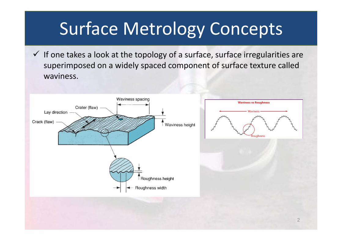
If one takes a look at the topology of a surface, surface irregularities are superimposed on a widely spaced component of surface texture called waviness.
Surface Metrology Concepts
2

Surface irregularities arise primarily due to the following factors:
Feed marks of cutting tools Chatter marks on the work‐piece due to vibrations caused during the
manufacturing operation Irregularities on the surface due to rupture of work‐piece material
during metal cutting operation Surface variations caused due to deformation of work‐piece under
the action of cutting forces Irregularities in the machine tool itself such as lack of straightness of
guide ways
Surface Irregularities
3

Roughness
Waviness
Lay
Flaws
Surface texture
Error of Form
Terminology
4
5
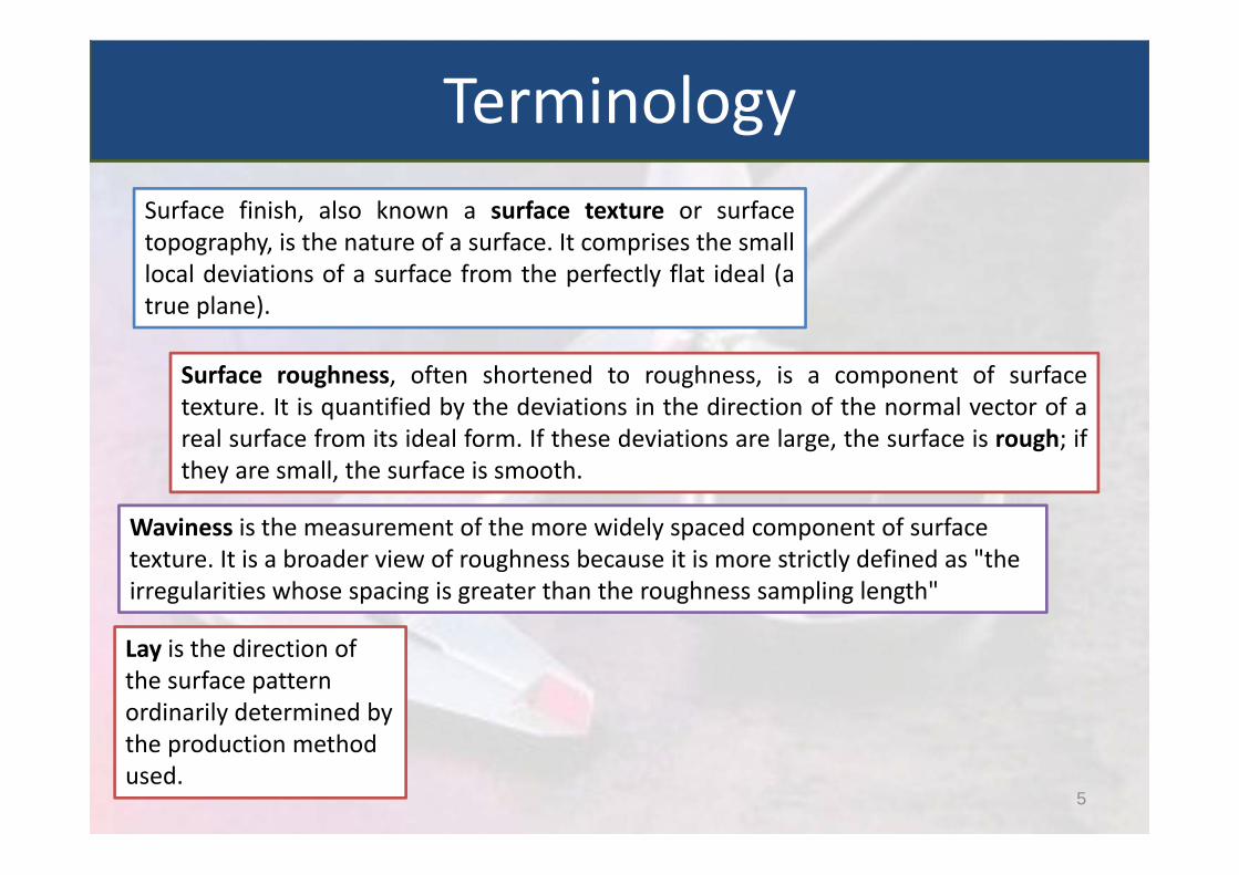
Surface finish, also known a surface texture or surfacetopography, is the nature of a surface. It comprises the smalllocal deviations of a surface from the perfectly flat ideal (atrue plane).
Surface roughness, often shortened to roughness, is a component of surfacetexture. It is quantified by the deviations in the direction of the normal vector of areal surface from its ideal form. If these deviations are large, the surface is rough; ifthey are small, the surface is smooth.
Waviness is the measurement of the more widely spaced component of surface texture. It is a broader view of roughness because it is more strictly defined as "the irregularities whose spacing is greater than the roughness sampling length"
Lay is the direction of the surface pattern ordinarily determined by the production method used.
Terminology
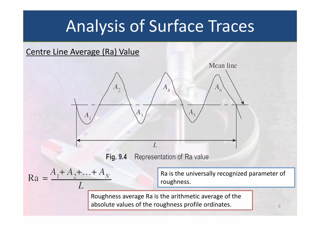
Centre Line Average (Ra) Value
Analysis of Surface Traces
6
Roughness average Ra is the arithmetic average of theabsolute values of the roughness profile ordinates.
Ra is the universally recognized parameter of roughness.
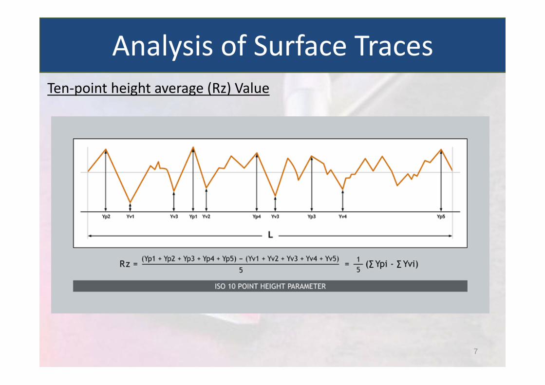
Ten‐point height average (Rz) Value
Analysis of Surface Traces
7
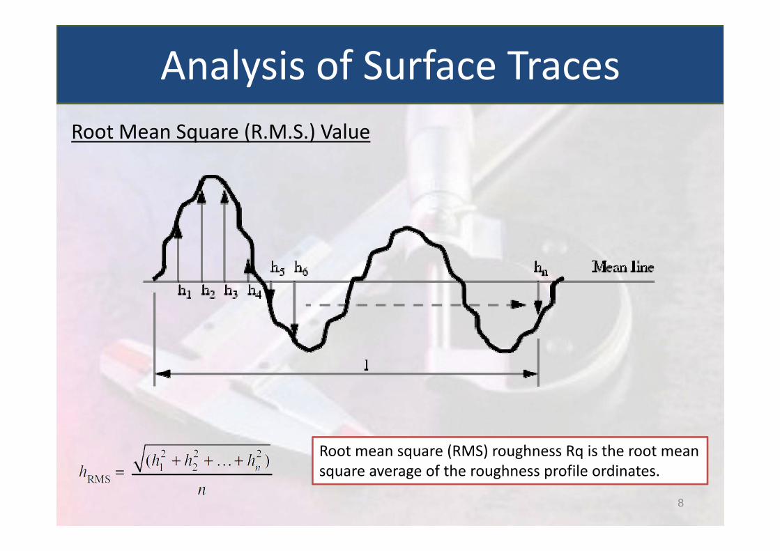
Root Mean Square (R.M.S.) Value
Analysis of Surface Traces
8
Root mean square (RMS) roughness Rq is the root meansquare average of the roughness profile ordinates.

9
Analysis of Surface Traces
10
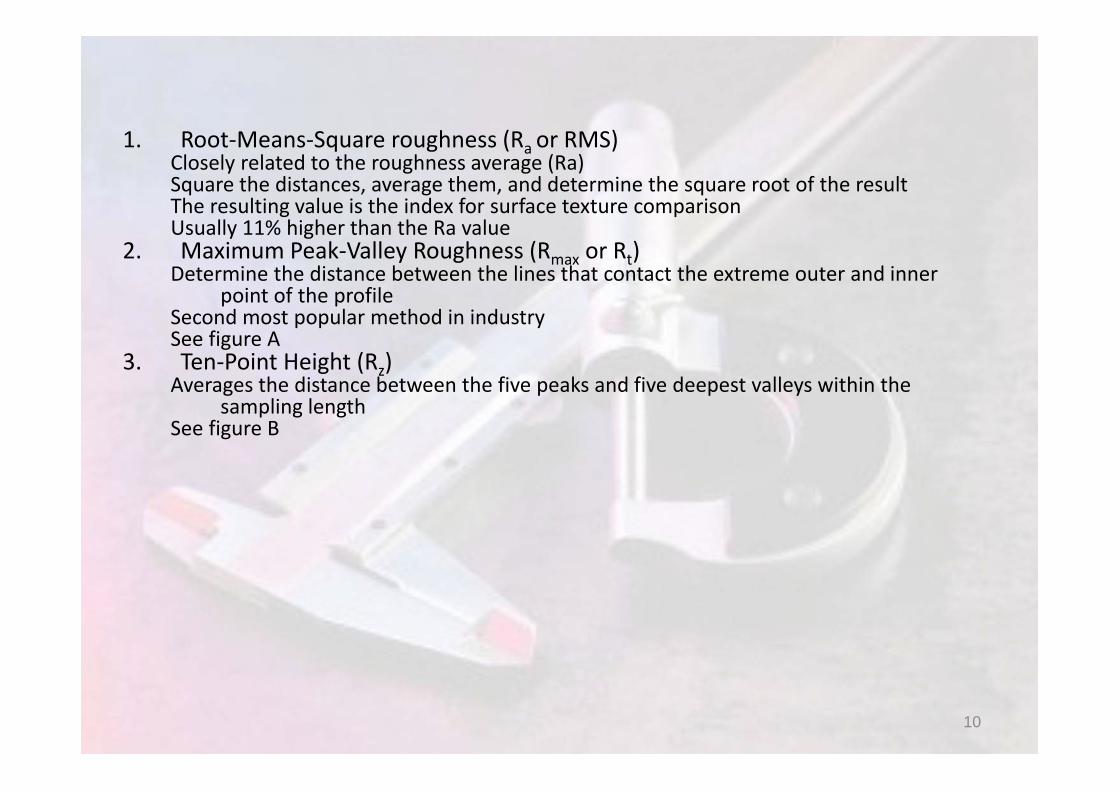
1. Root‐Means‐Square roughness (Ra or RMS)Closely related to the roughness average (Ra)Square the distances, average them, and determine the square root of the resultThe resulting value is the index for surface texture comparisonUsually 11% higher than the Ra value
2. Maximum Peak‐Valley Roughness (Rmax or Rt)Determine the distance between the lines that contact the extreme outer and inner
point of the profileSecond most popular method in industrySee figure A
3. Ten‐Point Height (Rz)Averages the distance between the five peaks and five deepest valleys within the
sampling lengthSee figure B
11
Analysis of Surface Traces
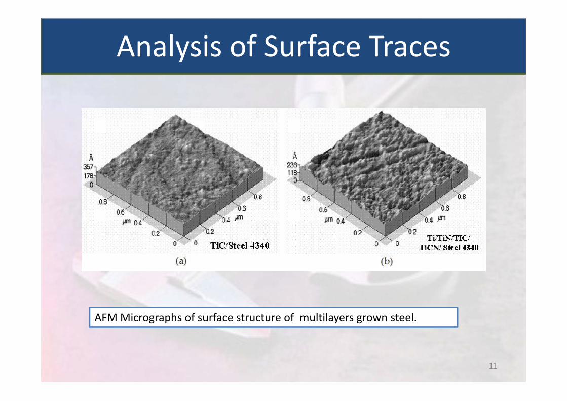
AFM Micrographs of surface structure of multilayers grown steel.
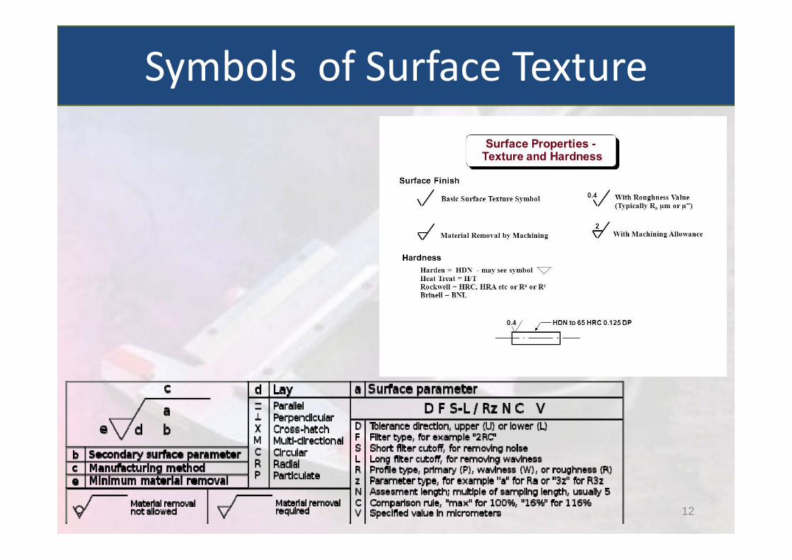
Symbols of Surface Texture
12

There are basically two approaches for the measurement of surface finish, namely, by comparison and direct measurement.
The former is the simpler of the two, but is more subjective in nature. The comparative method advocates assessment of surface texture by observation or feel of the surface.
Direct measurement enables a numerical value to be assigned to the surface finish.
Methods of Measuring Surface Finish
13
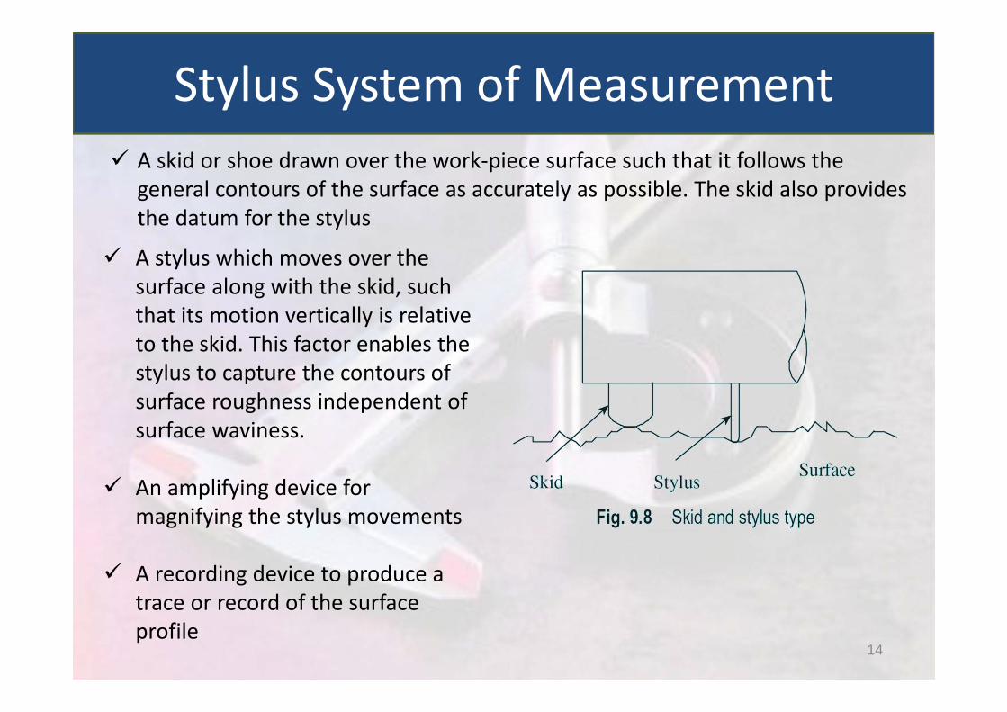
A skid or shoe drawn over the work‐piece surface such that it follows the general contours of the surface as accurately as possible. The skid also provides the datum for the stylus
A stylus which moves over the surface along with the skid, such that its motion vertically is relative to the skid. This factor enables the stylus to capture the contours of surface roughness independent of surface waviness.
An amplifying device for magnifying the stylus movements
A recording device to produce a trace or record of the surface profile
Stylus System of Measurement
14

This is a mechanical‐optical instrument designed by Dr Tomlinson of the National Physical laboratory of U.K.
Tomilson Surface Meter
15
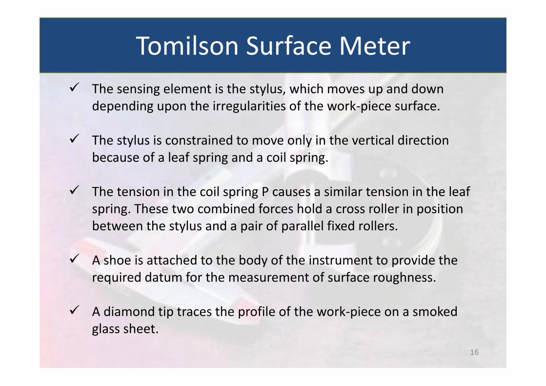
The sensing element is the stylus, which moves up and down depending upon the irregularities of the work‐piece surface.
The stylus is constrained to move only in the vertical direction because of a leaf spring and a coil spring.
The tension in the coil spring P causes a similar tension in the leaf spring. These two combined forces hold a cross roller in position between the stylus and a pair of parallel fixed rollers.
A shoe is attached to the body of the instrument to provide the required datum for the measurement of surface roughness.
A diamond tip traces the profile of the work‐piece on a smoked glass sheet.
Tomilson Surface Meter
16
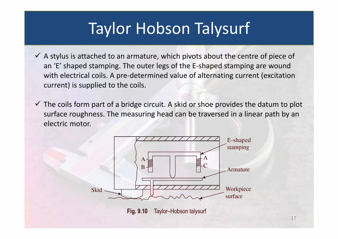
A stylus is attached to an armature, which pivots about the centre of piece of an ‘E’ shaped stamping. The outer legs of the E‐shaped stamping are wound with electrical coils. A pre‐determined value of alternating current (excitation current) is supplied to the coils.
The coils form part of a bridge circuit. A skid or shoe provides the datum to plot surface roughness. The measuring head can be traversed in a linear path by an electric motor.
Taylor Hobson Talysurf
17
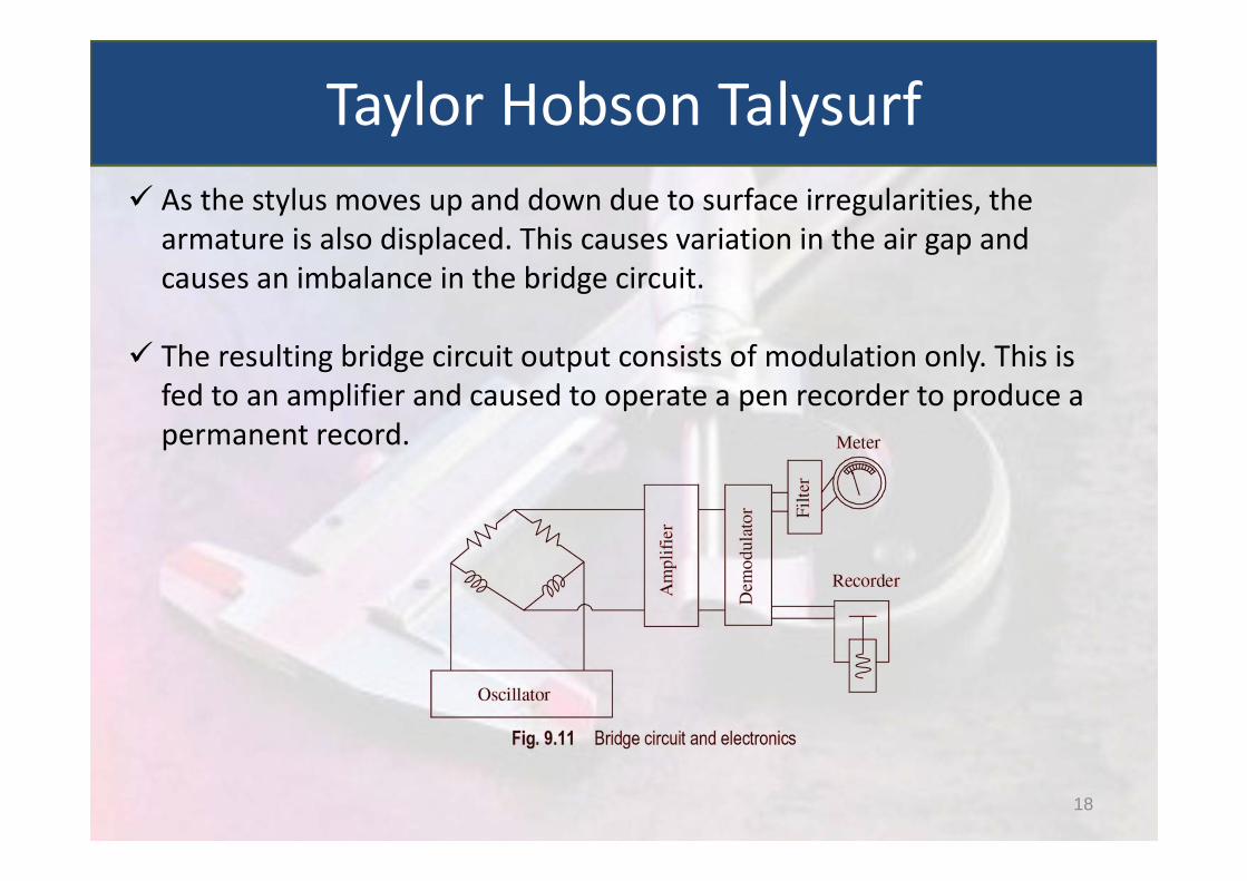
As the stylus moves up and down due to surface irregularities, the armature is also displaced. This causes variation in the air gap and causes an imbalance in the bridge circuit.
The resulting bridge circuit output consists of modulation only. This is fed to an amplifier and caused to operate a pen recorder to produce a permanent record.
Taylor Hobson Talysurf
18

Skids simplify surface assessment while using stylus instruments. However, there is distortion because of phase relationship between the stylus and the skid.
In case A, the stylus and the skid are in phase. Therefore, roughness (the primary texture) will be relatively undistorted.
In case B, the two are out of phase. In this situation, waviness superimposes in the roughness reading and is misleading.
In case C also the stylus and skid are out of phase, resulting in unrealistic interpretation of roughness value
Wavelength, Frequency and Cutoff
19
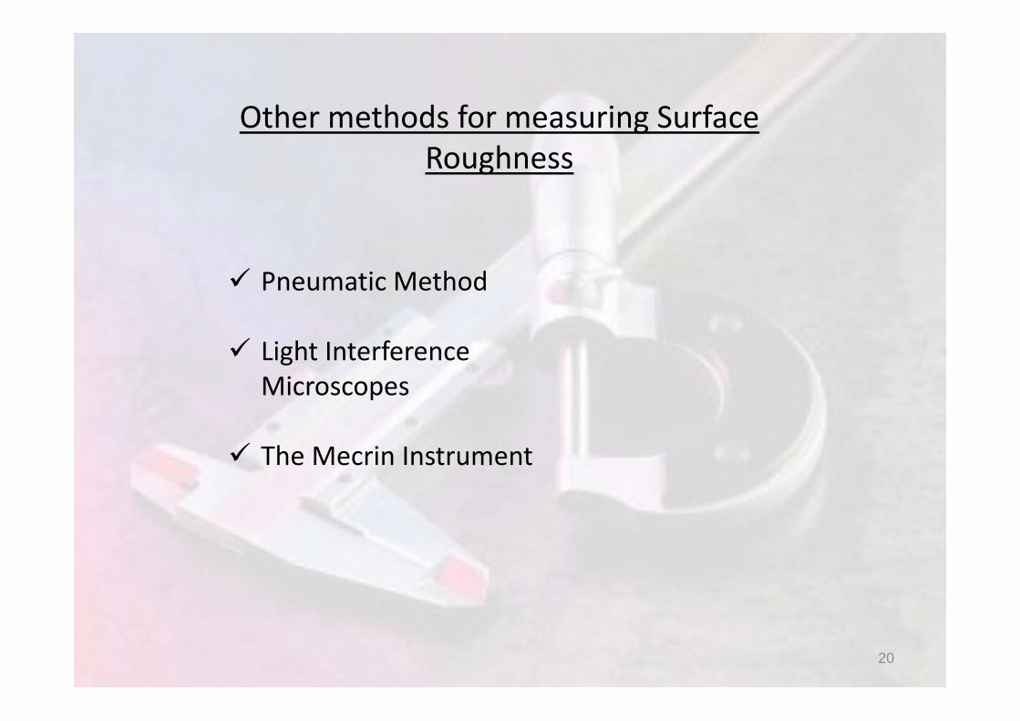
Other methods for measuring Surface Roughness
Pneumatic Method
Light Interference Microscopes
The Mecrin Instrument
20