METRIC MIL-PRF-32466A SUPERSEDING MIL-PRF-32466 26...
87
METRIC MIL-PRF-32466A SUPERSEDING MIL-PRF-32466 26 June 2013 PERFORMANCE SPECIFICATION SYSTEM SPECIFICATION FOR ENHANCED CONTROLLED IMAGE BASE (ECIB) This specification is approved for use by all Departments and Agencies of the Department of Defense. Comments, suggestions, or questions on this document should be addressed to the National Geospatial-Intelligence Agency (NGA), ATTN: Departmental Standardization Officer, 3838 Vogel Road, Arnold, MO 63010-6238, Mail Stop L18, or by e-mail to [email protected]. Since contact information can change, you may want to verify the currency of this address information using the ASSIST Online database at https://assist.dla.mil. AMSC N/A AREA GINT
Transcript of METRIC MIL-PRF-32466A SUPERSEDING MIL-PRF-32466 26...

METRIC
MIL-PRF-32466A
SUPERSEDING
MIL-PRF-32466
26 June 2013
PERFORMANCE SPECIFICATION
SYSTEM SPECIFICATION FOR
ENHANCED CONTROLLED IMAGE BASE (ECIB)
This specification is approved for use by all Departments and
Agencies of the Department of Defense.
Comments, suggestions, or questions on this document should be
addressed to the National Geospatial-Intelligence Agency (NGA),
ATTN: Departmental Standardization Officer, 3838 Vogel Road,
Arnold, MO 63010-6238, Mail Stop L18, or by e-mail to
[email protected]. Since contact information can change, you may want
to verify the currency of this address information using the ASSIST
Online database at https://assist.dla.mil.
AMSC N/A AREA GINT
MIL-PRF-32466A
2
1. SCOPE
1.1 Scope. This specification provides requirements for
the preparation and use of the National Geospatial-Intelligence
Agency’s (NGA) Enhanced Controlled Image Base (ECIB). ECIB files
are physically formatted within a National Imagery Transmission
Format 2.1 (NITF 2.1) file (MIL-STD-2500C).
1.2 Purpose. The purpose of this document is to specify
the data format and characteristics of ECIB for producers and
users.
1.3 Resolution. The Enhanced Controlled Image Base product
can be produced at multiple resolutions. The most common
resolutions are 0.5, 1, and 5 meter. ECIB will also allow for
the option of non-standard or native resolution (e.g. airborne
sources).
2. APPLICABLE DOCUMENTS
2.1 General. The documents listed in this section are
referenced in sections 3, 4, 5, or 6 of this specification. This
section does not include documents cited in other sections of
this specification or recommended for additional information or
as examples. While every effort has been made to ensure the
completeness of this list, document users are cautioned that
they must meet all specified requirements of documents cited in
sections 3, 4, 5 or 6 of this specification whether or not they
are listed.
2.2 Government documents.
2.2.1 Specifications, standards, and handbooks. The
following specifications, standards, and handbooks form a part
of this document to the extent specified herein. Unless
otherwise specified, the issues of these documents are those
cited in the solicitation or contract.
INTERNATIONAL STANDARDIZATION AGREEMENTS
STANAG 2211 — Geodetic Datums, Projections, Grids and
Grid References.

MIL-PRF-32466A
3
DEPARTMENT OF DEFENSE SPECIFICATIONS
MIL-A-89007 — ARC Digitized Raster Graphics (ADRG)
MIL-PRF-32283 – Enhanced Compressed Raster Graphic
(ECRG)
MIL-PRF-89041A - Controlled Image Base (CIB)
DEPARTMENT OF DEFENSE STANDARDS
MIL-STD-2411 – Interface Standard Raster Product
Format
MIL-STD-2411-1 – Interface Standard Registered Data
Values for Raster Product Format
MIL-STD-2414 – Bar Coding for Geospatial Products
MIL-STD-2500C – National Imagery Transmission Format
Version 2.1
MIL-STD-600001 Mapping, Charting, and Geodesy Accuracy
(Copies of these documents are available online at
http://quicksearch.dla.mil/)1
The Digital Geographic Information Exchange Standard
(DIGEST), Edition 2.1 September 2000.
(Copies of this publication are available at:
https://www.dgiwg.org/digest/index.htm)1
2.2.2 Other Government documents, drawings, and
publications. The following other Government documents,
drawings, and publications form a part of this document to the
extent specified herein. Unless otherwise specified, the issues
are those cited in the solicitation.
STDI-0002-1_4.0 – The Compendium of Controlled
Extensions for The National Imagery Format (NITF)
volume 1, Tagged Record Extensions (TRE)
1 Links in this document are only valid as of the document’s publication date.
MIL-PRF-32466A
4
NGA.STND.0036_1.0.0_WGS84 - World Geodetic System 84
NGA.STND.0037_2.0_GRIDS - Datums, Ellipsoids, Grids,
and Grid Reference Systems
(Copies of these publications are available online from the
National System for Geospatial Intelligence (NSG) Standards
Registry at https://nsgreg.nga.mil/)
N-0205/98 NITFS Standards Compliance and
Interoperability Test & Evaluation Program Plan
(Copies of this publication are available online from the
National Geospatial-Intelligence Agency, NITF Technical Board
(NTB) at http://www.gwg.nga.mil/ntb/baseline/docs/n010598/)
2.3 Non-Government publications. The following documents
form a part of this document to the extent specified herein.
Unless otherwise specified, the issues of the documents are
those cited in the solicitation or contract.
ANSI/IEEE Std. 754-2008 — IEEE Standard for Binary
Floating Point Arithmetic
ANSI/IEEE 1003.1 — Portable Operating System Interface
for Computer Environments (POSIX)
(Copies of these publications are available from the American
National Standards Institute (ANSI) at
http://webstore.ansi.org/ansidocstore)
ISO 9660:1988 — Information Processing, Volume and
File Structure of Optical Data Discs (CD-ROM) for
Information Interchange.
ISO/IEC 10149:1995 — Information Technology — Data
Interchange on Read-Only 120 mm CD-ROM
ISO/IEC 16448:2002 — Information Technology — 120 mm
DVD – Read-only disk
ISO/IEC 13346 Parts 1-5 — Volume and File Structure of
Write-Once and Rewriteable Media Using Nonsequential
Recording (NSR) for Information Interchange

MIL-PRF-32466A
5
ISO/IEC 15444-1:2004 — Information Technology - JPEG
2000 image coding system: core coding system
(Copies of these publications are available from the
International Organization for Standardization (ISO) at
http://www.iso.org/iso/en/prods-services/ISOstore/store.html)
BPJ2K01.10 — ISO/IEC BIIF Profile for JPEG2000,
Version 01.10
(Copies of this publication are available online from the
National Geospatial-Intelligence Agency, NITF Technical Board
NTB) at www.gwg.nga.mil/ntb/baseline/documents.html
ESRI Shapefile Technical Description – An ESRI White
Paper – July 1998
(Copies of this publication are available from Adobe at
http://www.esri.com/library/whitepapers/pdfs/shapefile.pdf)
Extensible Markup Language (XML) 1.0 (Third Edition)
(Copies of this publication are available at
http://www.w3.org/TR/2004/REC-xml-20040204/)
2.4 Order of precedence. In the event of a conflict
between the text of this document and the references cited
herein, the text of this document takes precedence. In order to
minimize potential conflicts within this document and associated
references the document was validated using the 5-step Standards
Validation testing approach as set forth in section 2.0 of NITFS
Standards Compliance and Interoperability Test and Evaluation
Program Plan, N-0105/98. Following the procedures set forth in
N-0105/98 will provide a high degree of confidence that the
document is technically correct, consistent, complete, testable
and implementable, prior to fielding by developers.
3. REQUIREMENTS
3.1 First article. The sample shall be inspected and
approved under appropriate provisions of the production
contract. The contracting officer shall specify the appropriate
type of first article and the number of units to be furnished.
MIL-PRF-32466A
6
The contracting officer shall also include arrangements for
selection, inspection, and approval of the first article.
3.2 Horizontal Accuracy.
a. The horizontal accuracy of ECIB data depends on the
accuracy of the imagery support data of the sensor capturing the
image source from which the ECIB was derived and the accuracy of
the digital elevation model (DEM) used to orthorectify the
image. The horizontal accuracy attribute within the ECIB frame
file defines the accuracy for each areal extent. Each Areal
extent is defined as a singular image and DEM extent.
b. The absolute horizontal accuracy is listed in the AAH
field of the ACCHZB extension for the particular image source
utilized in production. The relative horizontal accuracy is
listed in the APH field of the ACCHZB extension. Accuracies
shall be determined relative to a 90% Circular Map Accuracy. The
accuracy error attributable to compressing the ECIB data
contributes insignificantly to the total accuracy of the
product.
3.3 Vertical Accuracy. Vertical Accuracy is not applicable
to this product specification.
3.4 Resolution. The spatial resolution of the ECIB data
depends on the spatial resolution of the image source from which
the product is derived and any processing steps which affect the
resolution or GSD. Note that in this specification, the terms
"GSD" and "resolution" are used interchangeably. The spatial
resolution of the ECIB product shall be produced based on source
data and customer requirements.
3.5 Horizontal Datum. The horizontal datum for ECIB shall
be WGS-84, as defined by the NSG Standard.
3.6 Product Description. The ECIB products shall conform
to this specification. The processing of ECIB includes Joint
Photographic Experts Group (JPEG) 2000 compression. ECIB images
may be Red-Green-Blue (RGB) or panchromatic. Images will be
processed into an ECIB product with a specified resolution which
will be reflected in the NGA Reference Number (NRN) for the
product. Individual ECIB products are uniquely referenced by the
exchange media that was associated with the original data
delivery from the producer. An individual ECIB product may
consist of a single 1 degree by 1 degree cell, multiple 1 degree
by 1 degree cells, or a quarter cell (1 quadrant of a 1 degree
MIL-PRF-32466A
7
cell). The product will be sized in accordance with the
allowable space on the exchange media or as defined in the
Product Specific Guidance. An ECIB Volume is defined to be the
content that resides on one physical exchange media. The terms
product and volume may be used interchangeably. Therefore
multiple products may not reside on an exchange media, and a
product may not span multiple volumes.
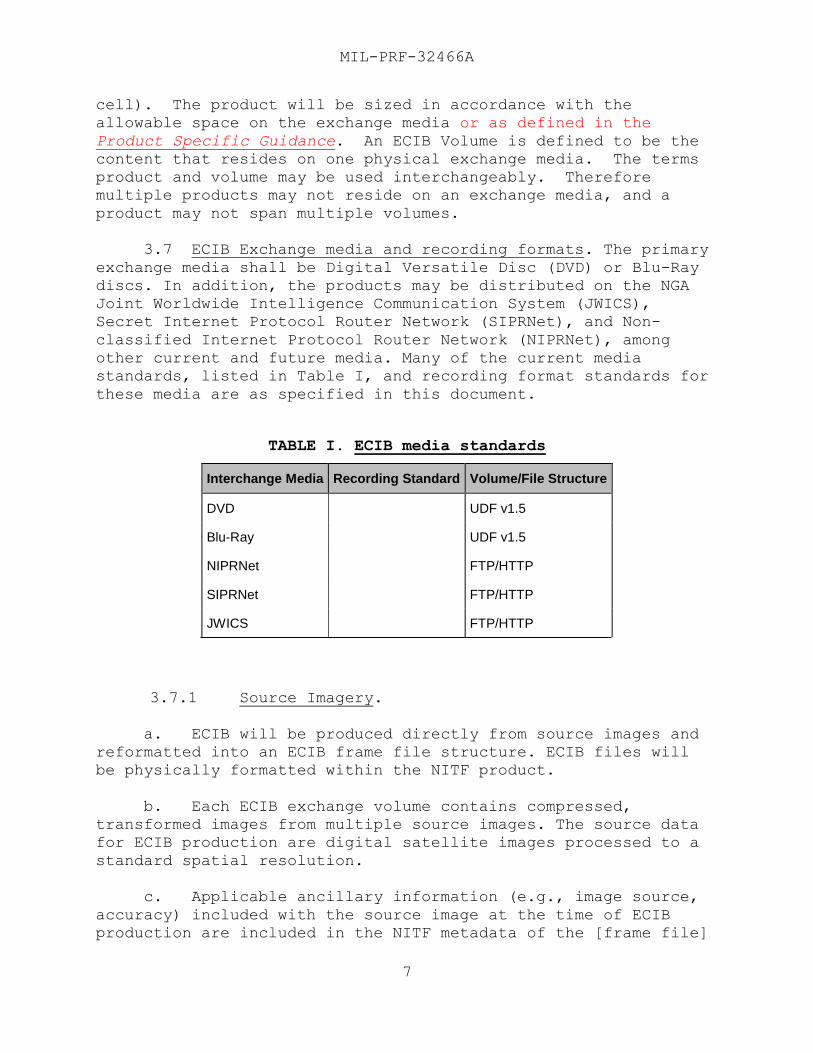
3.7 ECIB Exchange media and recording formats. The primary
exchange media shall be Digital Versatile Disc (DVD) or Blu-Ray
discs. In addition, the products may be distributed on the NGA
Joint Worldwide Intelligence Communication System (JWICS),
Secret Internet Protocol Router Network (SIPRNet), and Non-
classified Internet Protocol Router Network (NIPRNet), among
other current and future media. Many of the current media
standards, listed in Table I, and recording format standards for
these media are as specified in this document.
TABLE I. ECIB media standards
3.7.1 Source Imagery.
a. ECIB will be produced directly from source images and
reformatted into an ECIB frame file structure. ECIB files will
be physically formatted within the NITF product.
b. Each ECIB exchange volume contains compressed,
transformed images from multiple source images. The source data
for ECIB production are digital satellite images processed to a
standard spatial resolution.
c. Applicable ancillary information (e.g., image source,
accuracy) included with the source image at the time of ECIB
production are included in the NITF metadata of the [frame file]
Interchange Media Recording Standard Volume/File Structure
DVD UDF v1.5
Blu-Ray UDF v1.5
NIPRNet FTP/HTTP
SIPRNet FTP/HTTP
JWICS FTP/HTTP
MIL-PRF-32466A
8
and shapefile attributes. Source imagery data that are more
recent than the current version of a frame file or contain data
that are of higher quality (e.g., less cloud cover, <=30° off
nadir) are candidates for ECIB update data.
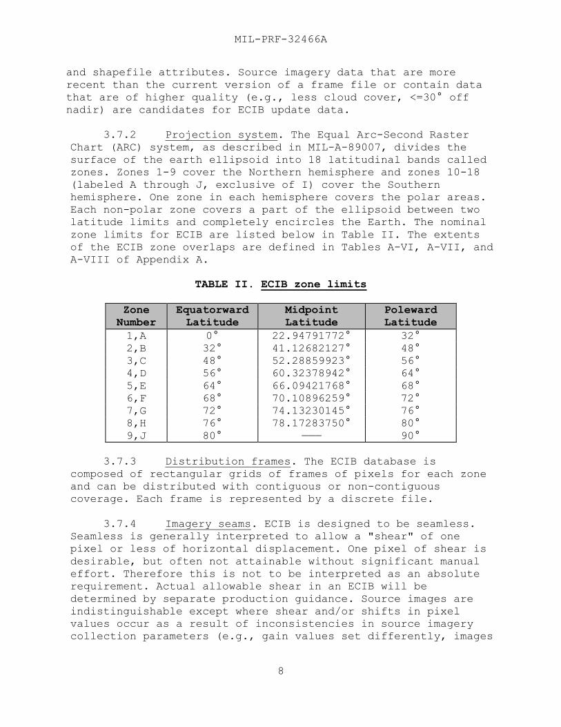
3.7.2 Projection system. The Equal Arc-Second Raster
Chart (ARC) system, as described in MIL-A-89007, divides the
surface of the earth ellipsoid into 18 latitudinal bands called
zones. Zones 1-9 cover the Northern hemisphere and zones 10-18
(labeled A through J, exclusive of I) cover the Southern
hemisphere. One zone in each hemisphere covers the polar areas.
Each non-polar zone covers a part of the ellipsoid between two
latitude limits and completely encircles the Earth. The nominal
zone limits for ECIB are listed below in Table II. The extents
of the ECIB zone overlaps are defined in Tables A-VI, A-VII, and
A-VIII of Appendix A.
TABLE II. ECIB zone limits
Zone
Number
Equatorward
Latitude
Midpoint
Latitude
Poleward
Latitude
1,A 0° 22.94791772° 32°
2,B 32° 41.12682127° 48°
3,C 48° 52.28859923° 56°
4,D 56° 60.32378942° 64°
5,E 64° 66.09421768° 68°
6,F 68° 70.10896259° 72°
7,G 72° 74.13230145° 76°
8,H 76° 78.17283750° 80°
9,J 80° ——— 90°
3.7.3 Distribution frames. The ECIB database is
composed of rectangular grids of frames of pixels for each zone
and can be distributed with contiguous or non-contiguous
coverage. Each frame is represented by a discrete file.
3.7.4 Imagery seams. ECIB is designed to be seamless.
Seamless is generally interpreted to allow a "shear" of one
pixel or less of horizontal displacement. One pixel of shear is
desirable, but often not attainable without significant manual
effort. Therefore this is not to be interpreted as an absolute
requirement. Actual allowable shear in an ECIB will be
determined by separate production guidance. Source images are
indistinguishable except where shear and/or shifts in pixel
values occur as a result of inconsistencies in source imagery
collection parameters (e.g., gain values set differently, images
MIL-PRF-32466A
9
collected on different dates.) Processing of the source imagery
into ECIB will include a brightness and/or contrast adjustment
in order to minimize such differences; however, it typically
will not be possible to eliminate all visual differences between
mosaicked images. ECIB image data from adjacent frames abut
exactly to provide unbroken coverage. However, gaps in coverage
may occur as a result of incomplete source image data. In the
case where source imagery is extremely dark or light (e.g.,
contains features that are unrecognizable), data will be
enhanced such that contrast will be heightened over large areas
and features are recognizable without further enhancement by the
user. No artificial seams (i.e., along geocell or frame
boundaries) will be introduced to data during processing from
source to final ECIB product except in the case along the degree
boundary where an adequate DEM is not available for the adjacent
cell. In addition ECIB volumes should be radiometrically
balances with adjacent volumes such that contrast is minimized
without degrading the product frames. At a minimum, ECIB
producers should present their approach to both radiometric
balancing and contrast enhancement for review before production
begins.
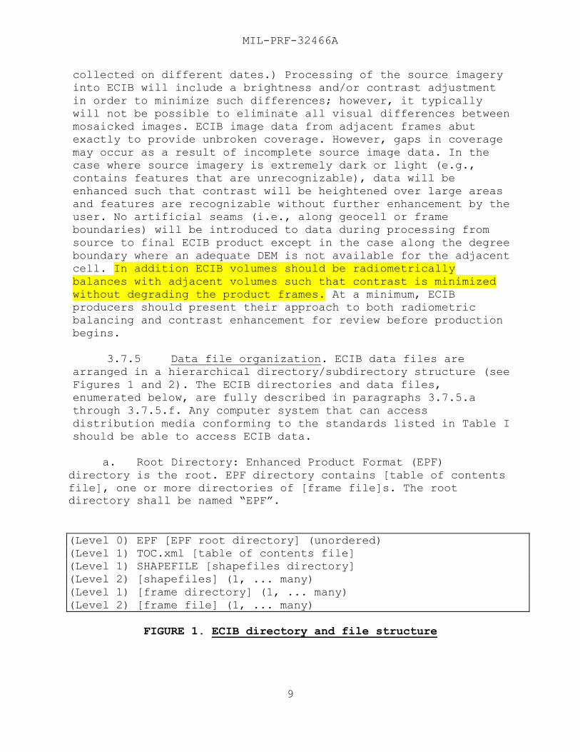
3.7.5 Data file organization. ECIB data files are
arranged in a hierarchical directory/subdirectory structure (see
Figures 1 and 2). The ECIB directories and data files,
enumerated below, are fully described in paragraphs 3.7.5.a
through 3.7.5.f. Any computer system that can access
distribution media conforming to the standards listed in Table I
should be able to access ECIB data.
a. Root Directory: Enhanced Product Format (EPF)
directory is the root. EPF directory contains [table of contents
file], one or more directories of [frame file]s. The root
directory shall be named “EPF”.
(Level 0) EPF [EPF root directory] (unordered)
(Level 1) TOC.xml [table of contents file]
(Level 1) SHAPEFILE [shapefiles directory]
(Level 2) [shapefiles] (1, ... many)
(Level 1) [frame directory] (1, ... many)
(Level 2) [frame file] (1, ... many)
FIGURE 1. ECIB directory and file structure
MIL-PRF-32466A
10
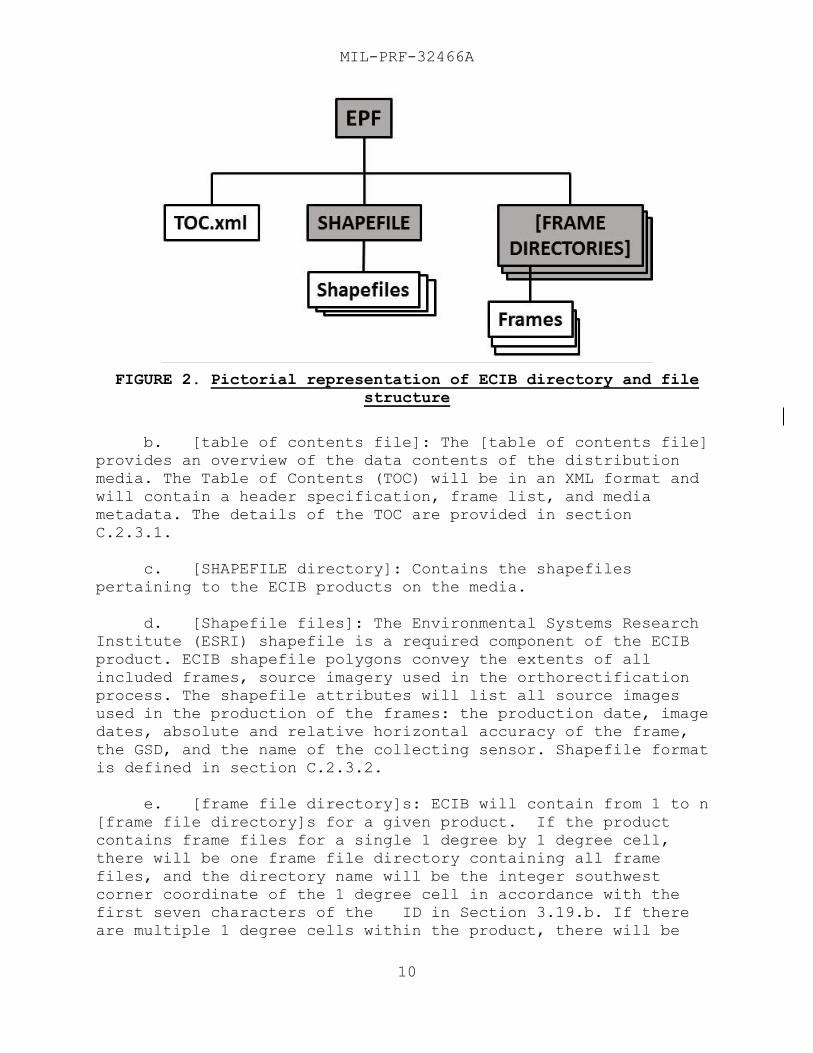
FIGURE 2. Pictorial representation of ECIB directory and file
structure
b. [table of contents file]: The [table of contents file]
provides an overview of the data contents of the distribution
media. The Table of Contents (TOC) will be in an XML format and
will contain a header specification, frame list, and media
metadata. The details of the TOC are provided in section
C.2.3.1.
c. [SHAPEFILE directory]: Contains the shapefiles
pertaining to the ECIB products on the media.
d. [Shapefile files]: The Environmental Systems Research
Institute (ESRI) shapefile is a required component of the ECIB
product. ECIB shapefile polygons convey the extents of all
included frames, source imagery used in the orthorectification
process. The shapefile attributes will list all source images
used in the production of the frames: the production date, image
dates, absolute and relative horizontal accuracy of the frame,
the GSD, and the name of the collecting sensor. Shapefile format
is defined in section C.2.3.2.
e. [frame file directory]s: ECIB will contain from 1 to n
[frame file directory]s for a given product. If the product
contains frame files for a single 1 degree by 1 degree cell,
there will be one frame file directory containing all frame
files, and the directory name will be the integer southwest
corner coordinate of the 1 degree cell in accordance with the
first seven characters of the ID in Section 3.19.b. If there
are multiple 1 degree cells within the product, there will be
MIL-PRF-32466A
11
one frame file directory for each 1 degree cell, each containing
the frame files that are within the 1 degree cell boundary. No
product will cross arc zones. Each of the frame file directory
names shall be based upon the integer southwest corner
coordinate of the particular 1 degree cell in accordance with
the first seven characters of the Product Item ID in Section
3.19.b. If the product consists of a single cell, there will
be one frame file directory containing all frame files, and the
directory name will be the integer southwest corner coordinate
of the 1 degree cell in accordance with the first seven
characters of the Product Item ID in Section 3.19.b, and
appended with the extent code [A,B,C,D] associated with the
quadrant as stated in Section 3.19.b.
f. [frame file]s: The [frame file]s contain the image and
support data for the geographic frames on an ECIB product.
Particular details of some of the contents of the frame file are
described in section C.2.1 (ECIB NITF 2.1 File Structure). The
frame file naming convention shall be in accordance with this
specification, and is described in section A.2.6.1 (Frame naming
convention).
3.8 Frame structure.
3.8.1 Pixel spacing for ECIB. In the nonpolar zones,
pixel spacing is the nominal ground sample distance (GSD) of the
orthorectified source images in both the east-west and north-
south directions on the WGS-84 ellipsoid. In the polar zones,
pixel spacing is the minimal GSD of the orthorectified source
images in both X and Y axes of the polar stereographic
projection.
a. Within a non polar zone, pixel spacing is fixed in units
of arc-seconds of latitude per pixel and arc-seconds of
longitude per pixel.
b. The numbers of ECIB pixels in both latitudinal and
longitudinal directions shall be adjusted so that there are
integral numbers of frames per zone. In the polar zone, the
number of ECIB pixels is adjusted so that there is an even
number of frames across the zone in each dimension.
MIL-PRF-32466A
12
3.8.2 Frame Description.
a. Each frame shall comprise a rectangular array of 2304
by 2304 pixels (5,308,416 pixels). For other resolutions, the
frame size will need to be calculated with the equations
provided in Appendix A. ECIB frames will not be tiled into
subframes, but a virtual grid of 6 by 6 virtual subframes is
used only for mathematical purposes in this specification (36
virtual subframes). Each virtual subframe shall comprise a
rectangular array of 384 by 384 output pixels (147,456 pixels).
For other resolutions, K (virtual subframe size) will need to be
calculated with the equations provided in Appendix A.
b. All frames within a zone shall abut in a mutually
exclusive manner without any pixel overlap or pixel redundancy,
except as noted in section 3.7.4 (Imagery seams). The distance
between a pixel that falls on a frame border and its neighbor in
the adjacent frame shall equal the GSD for the product. The
northern and southern boundaries of a zone generally will not
fall exactly on the northern and southern boundaries of a frame.
There shall be frame overlap between the zones, as defined in
Appendix A.
c. For 5.0 meter, 1.0 meter and 0.5 meter ECIB products
(2304 x 2304 pixels), Appendix A lists the number of frame rows
and columns in each zone for the latitudinal and longitudinal
directions, East-West pixel spacing constants (i.e., the number
of pixels for 360° longitude), North-South pixel spacing
constants (i.e., number of pixels in 90° from equator to pole.
These are examples, values for other ECIB resolutions may be
generated by following the same computations.
d. The midpoint latitude for each zone shall be the same
as for the ADRG ARC-zone schematic (see 3.7.2, Table II, ECIB
zone limits).
3.8.3 Numbering and origin conventions.
a. All index numbers shall start from 0. The origin for
the pixel numbering within frames shall be from the upper left
corner. Pixels shall be counted in row-major order from the
origin. Appendix A provides a set of coordinate conversions
between row/column coordinate of a pixel within a frame, and the
latitude and longitude of the corresponding point, based on the
coordinate information provided within each frame.
MIL-PRF-32466A
13
b. In addition, ECIB frames may be considered to form
conceptual “rows” and “columns” within zones. Section A.2.6
(Frame conventions) uses this concept to define the naming
convention of frames for various resolutions by using the
resolution and zone specific "frame number”. The rows and
columns are numbered from 0. The origin for counting non-polar
frame rows and columns in both the northern and southern
hemispheres is the southernmost latitude of the zone, and 180°
west longitude, with columns counted in an easterly direction
from that origin. The origin for counting polar frames is the
lower-left corner of the polar zone, with rows and columns
numbered from that origin. Section A.2 (Coordinate
Transformations) provides the coordinate conversions for points
within a frame file.
3.8.4 Non-polar frame overlap.
a. The longitudinal and latitudinal extents of the zones
in the southern hemisphere are identical to those in the
northern hemisphere.
b. Rows of frames from different zones do not have the
same longitudinal extent since the longitudinal pixel intervals
differ.
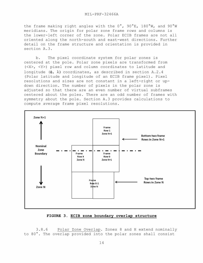
c. For each non-polar zone N, the top-most frame row of
that zone corresponds (in latitude) with the bottom-most frame
row of zone N+1 (as depicted in
d. FIGURE 3, ECIB zone boundary overlap structure). Thus
the frames at the top and bottom rows of each zone shall overlap
frames of those zones above and below. In each ARC zone, the
lower-left pixel in lower-left frame is edge-aligned with the
ARC system origin.
3.8.5 Frame structure for polar regions. The ECIB frame
structure is unique in the polar regions. ECIB shall use a polar
stereographic projection, in which meridians (constant
longitude) are plotted as radii emanating from the poles, and
parallels (constant latitude) are plotted as concentric circles
that are centered at the poles.
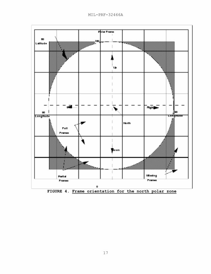
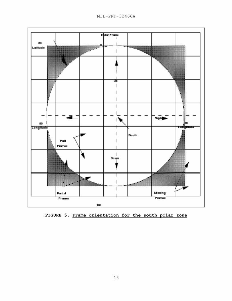
a. The north and south polar zones, 9 and J, are depicted
in FIGURE 4 and 5, respectively. These zones are circular with
the pole at the center and the radius being the distance from
the pole to approximately 80° (north or south) latitude. The
polar frame structure is square. The center frame is positioned
with the pole in the exact center of that frame and the sides of
MIL-PRF-32466A
14
the frame making right angles with the 0°, 90°E, 180°W, and 90°W
meridians. The origin for polar zone frame rows and columns is
the lower-left corner of the zone. Polar ECIB frames are not all
oriented along the north-south and east-west directions. Further
detail on the frame structure and orientation is provided in
section A.3.
b. The pixel coordinate system for polar zones is
centered at the pole. Polar zone pixels are transformed from
(<X>, <Y>) pixel row and column coordinates to latitude and
longitude (, coordinates, as described in section A.2.4 (Polar latitude and longitude of an ECIB frame pixel). Pixel
resolutions and sizes are not constant in a left-right or up-
down direction. The number of pixels in the polar zone is
adjusted so that there are an even number of virtual subframes
centered about the poles. There are an odd number of frames with
symmetry about the pole. Section A.3 provides calculations to
compute average frame pixel resolutions.
FIGURE 3. ECIB zone boundary overlap structure
3.8.6 Polar Zone Overlap. Zones 8 and H extend nominally
to 80°. The overlap provided into the polar zones shall consist
MIL-PRF-32466A
15
of the one row of frames that “straddle” the 80° parallel. Polar
data will extend to and include the row of frames that straddle
the 80° parallel.
3.9 Coordinate reference systems.
3.9.1 Non-polar coordinates. Coordinates for row and
column pixels in the non-polar zones are proportional to WGS-84
latitude and longitude of features under the Equirectangular
projection (as defined in Map Projections—A Working Manual, page
90). The coordinate conversions for the non-polar case are in
sections A.2.2 and A.2.3.
3.9.2 Polar coordinates. Pixel coordinates in the polar
zones are proportional to rectangular coordinates of the
Azimuthal Equidistant projection, polar aspect, spherical form
(as defined in Map Projections—A Working Manual, page 191). The
coordinate conversions for the polar case are provided in
sections A.2.4 and A.2.5.
3.9.3 WGS-84 coordinates. The WGS-84 coordinates for
longitude and latitude in ECIB are signed values in the range
-180° <= longitude <= +180° and -90° <= latitude <= +90°.
3.10 Project Distortion. A nominal GSD is given for the various ECIB products. In order to view the earth ellipsoid as a
flat surface, it must be projected to a flat plane. This can be
accomplished using a projection which uses localized values in
which frames could not be seamlessly joined. In ECIB, the ARC
projection was chosen for use for several reasons including (1)
it provides a way to project the earth such that it is seamless
within zones, (2) the ARC system is used by CADRG, ECRG, and
CIB® data, which allows applications to more easily utilize the
data types, and (3) the ARC projection system retains a high
accuracy and causes minimal visual distortion.
3.10.1 Non-polar distortion. For the nonpolar zones,
some minor visual distortion is present due to a stretch (at the
poleward latitude) and shrink (at equatorward latitude) in the
east-west direction. There is no distortion (i.e., the nominal
pixel interval is true) along the parallel at the mid-latitude
of each zone.
3.10.2 Polar distortion. Some distortion occurs in the
polar zones as a result of the projection of the image pixels
MIL-PRF-32466A
16
into the polar stereographic projection. The amount of the
distortion and the resulting change in accuracy is minimal.
3.11 Image formats. Each ECIB product contains compressed, transformed images from multiple source images. A compressed
JPEG2000 image segment exists for each ECIB frame. In cases
where source imagery does not exist, blank areas of frames shall
be padded with zeroes in order to fully populate the frame
extent. The source polygons stored in the SNSPSB Tagged Record
Extensions (TRE) must be used to determine exact areas without
source. Consult the Product Specific Guidance for the number of
bands since many exploitation systems may not handle more than
the nominal three bands.
MIL-PRF-32466A
17
FIGURE 4. Frame orientation for the north polar zone
MIL-PRF-32466A
18
FIGURE 5. Frame orientation for the south polar zone
MIL-PRF-32466A
19
3.12 Source Support Data. Each ECIB interchange volume contains the following source support data:
a. Header data within the [table of contents file] and
[frame file]s that contain the critical configuration control
information needed by software application.
b. The [table of contents file] that describes the
geographic boundaries and locations of actual data, and
pathnames to the [frame file]s and their locations. Refer to
Section 3.13.1.
c. Attribute data gives important information about the
source image(s) such as accuracy and date of collection.
3.12.1 Orthorectification. Portions of one or more
source images are mosaicked together to form each frame file.
Source images are orthorectified to an elevation surface
referenced to DOD current standard ellipsoid which provides for
the removal of terrain relief and other distortions present
within the original source imagery.
3.12.2 Color reduction. An ECIB frame will use 8 bits
per pixel per band to the extent source imagery will be
resampled if applicable.
3.12.3 Compression algorithm. Spatial compression shall
be performed using JPEG 2000 with a standard compression ratio
of 15:1. The 9-7I Wavelet Transform with Irreversible Component
Transform (ICT) shall be used to compress the source image. No
internal tiling will occur, so the tile size shall be equal to
the frame size. Five (5) Decomposition layers will be used to
allow for six (6) viewing resolutions.
3.13 ECIB volume support data. Each ECIB volume shall contain support information for the frame files contained
therein. This information shall consist of:
TOC.xml file
Shapefiles containing source and frame extents on the
volume
These files describe the contents of the ECIB media, not
individual frames. Details about the above volume support data
are provided in section C.2.3.
MIL-PRF-32466A
20
3.13.1 The table of contents (TOC) file. The structure
and data types for the table of contents file are defined in
section C.2.3.1.
3.13.2 The frame file. The data for each ECIB frame is
provided in separate frame files. ECIB frames shall be formatted
within a NITF 2.1 file. ECIB frames contain the JPEG2000
compressed image and a variety of metadata about the frame.
Details are provided in section C.2.
3.14 Storage requirements. Including overhead, the ECIB image data is approximately 15:1 compressed with respect to the
source image data. The storage requirements are discussed in
Appendix B. ECIB products on DVD and Blue-ray shall be sized
such that they will not span multiple volumes. Storage on
distribution media other than DVD and Blue-ray shall be
appropriate to the data capacity of that media.
3.15 ECIB decompression. All information required for decompression of an ECIB frame file is contained within the file
itself. Most importantly, software should be written to support
variable resolution (PPI).
3.16 ECIB frame updates. Changes to ECIB frame files (NITF image segment) shall require updates to the affected field
values in the NITF headers and TREs.
3.17 ECIB frame description. The optional Frame Description text segment is intended to be a placeholder for storing
additional metadata about ECIB frames.
3.18 Media labeling. ECIB Media will be labeled in accordance with ECIB Product Specific Guidance (PSG).
3.19 Catalog indexing. Each Media in the ECIB library shall be indexed to facilitate configuration management, including
updates, additions, and replacements. The format for NGA
Reference number shall be specified per DLA product
identification guidance:
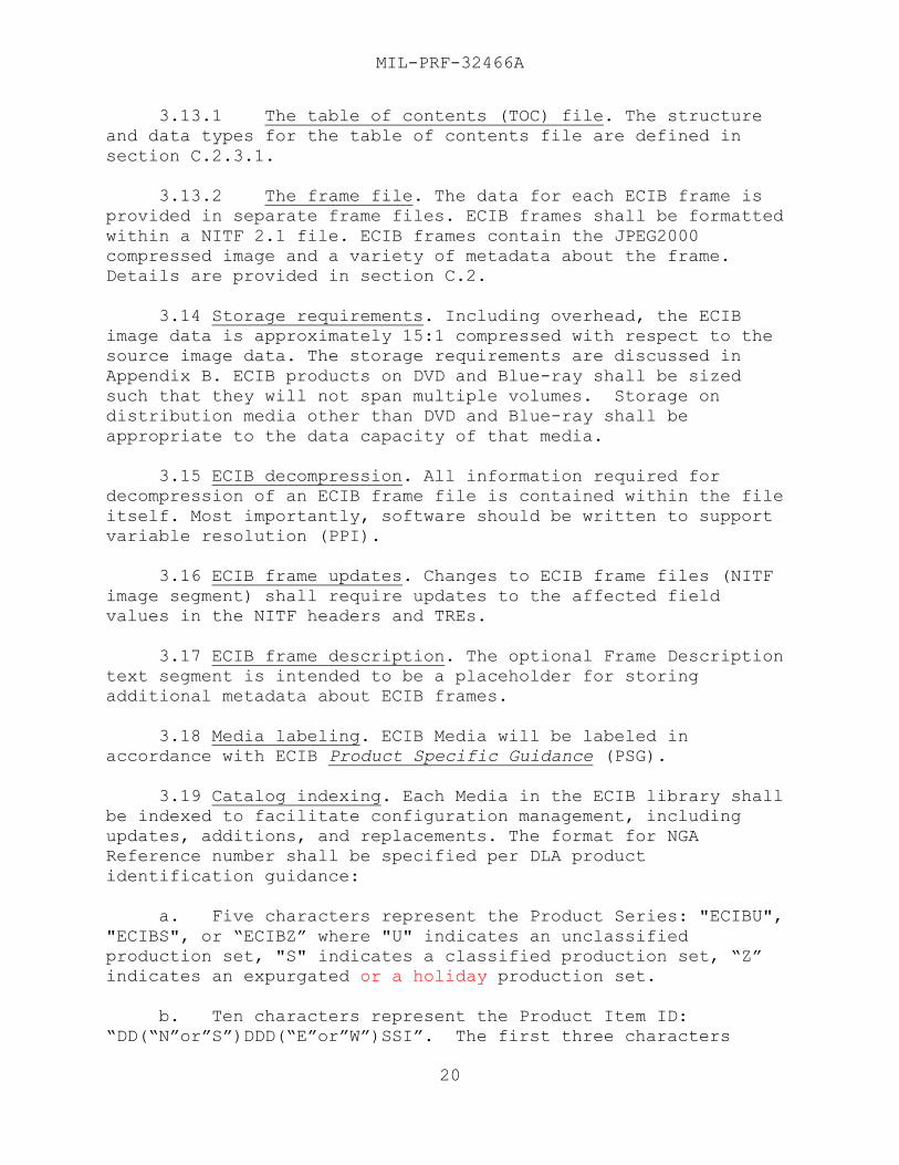
a. Five characters represent the Product Series: "ECIBU",
"ECIBS", or “ECIBZ” where "U" indicates an unclassified
production set, "S" indicates a classified production set, “Z”
indicates an expurgated or a holiday production set.
b. Ten characters represent the Product Item ID:
“DD(“N”or”S”)DDD(“E”or”W”)SSI”. The first three characters
MIL-PRF-32466A
21
“DDx” is the southernmost extent of the product in integer
degrees latitude and ends with the letter “N” or “S” for
northern or southern hemisphere. The next four characters
“DDDx” is the westernmost extent of the product in integer
degrees longitude and ends with the letter “W” or “E” for
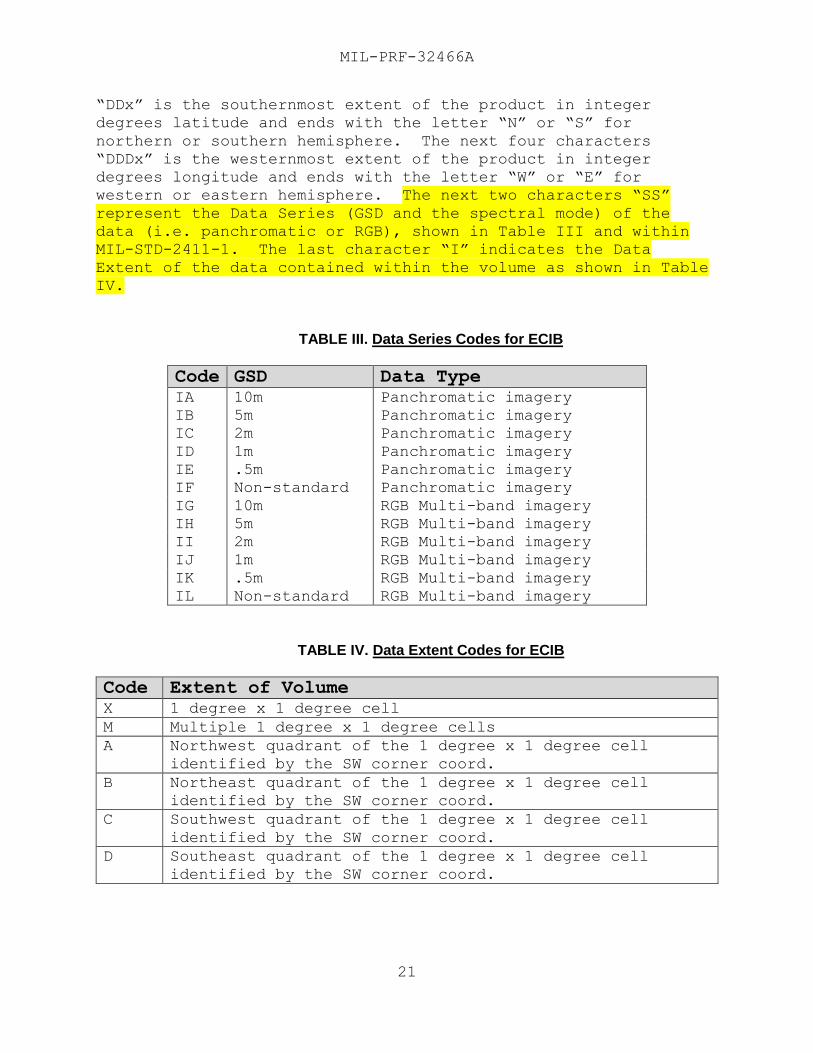
western or eastern hemisphere. The next two characters “SS”
represent the Data Series (GSD and the spectral mode) of the
data (i.e. panchromatic or RGB), shown in Table III and within
MIL-STD-2411-1. The last character “I” indicates the Data
Extent of the data contained within the volume as shown in Table
IV.
TABLE III. Data Series Codes for ECIB
Code GSD Data Type
IA 10m Panchromatic imagery
IB 5m Panchromatic imagery
IC 2m Panchromatic imagery
ID 1m Panchromatic imagery
IE .5m Panchromatic imagery
IF Non-standard Panchromatic imagery
IG 10m RGB Multi-band imagery
IH 5m RGB Multi-band imagery
II 2m RGB Multi-band imagery
IJ 1m RGB Multi-band imagery
IK .5m RGB Multi-band imagery
IL Non-standard RGB Multi-band imagery
TABLE IV. Data Extent Codes for ECIB
Code Extent of Volume
X 1 degree x 1 degree cell
M Multiple 1 degree x 1 degree cells
A Northwest quadrant of the 1 degree x 1 degree cell
identified by the SW corner coord.
B Northeast quadrant of the 1 degree x 1 degree cell
identified by the SW corner coord.
C Southwest quadrant of the 1 degree x 1 degree cell
identified by the SW corner coord.
D Southeast quadrant of the 1 degree x 1 degree cell
identified by the SW corner coord.
MIL-PRF-32466A
22
c. Three characters represent the edition number:
example: “001”.
d. The Volume ID shall be 18 characters in length, and is
created by the concatenation of the Product Series (characters
1-5), Product Item ID (characters 6-15), and Edition Number
(characters 16-18) in that order, as specified in Sections
3.19.a, 3.19.b, and 3.19.c.
e. Data Extent. For multi-cell volumes such as 5m the
ECIB volume will contain the “M” designator. Use the “X” of a
standard 1 degree cell. When the ECIB volume is divided into
quarter cells use the A,B,C,D designators to identify the
specific quarter cell. For oceanic volumes use the “M”
designator to identify the volume contains multiple cells.
3.20 Standard distribution. ECIB packaging will normally be based on GSD of the data.
3.21 Nonstandard distribution. In support of crisis, special, and/or reoccurring broad-based user requirements, ECIB
may be geopackaged vertically (all spatial resolutions) and with
other products covering discrete geographic regions. For
example, data sets can be identified for test ranges, major
training centers, crisis areas, or by other common thematic
content where integrated datasets with mixed data types and
levels of detail are needed by large numbers of users.
4. PACKAGING
4.1 Source Packaging. When actual packaging of material is
to be performed by DoD or in-house contract personnel, these
personnel need to contact the responsible packaging activity to
ascertain packaging requirements. Packaging requirements are
maintained by the Inventory Control Point's packaging activity
within the Military Service or Defense Agency, or within the
military service’s system Command. Packaging data retrieval is
available from the managing Military Department's or Defense
Agency's automated packaging files, media products, or by
contacting the responsible packaging activity.
5. NOTES
(This section contains information of a general or explanatory
nature that may be helpful, but is not mandatory.)
MIL-PRF-32466A
23
5.1 Intended use. This specification is intended to
provide guidelines for the preparation and use of ECIB data to
support various military weapons, C3I theater battle management,
mission planning, and digital moving map systems. ECIB data is
not a commercial product and is releasable only to DoD and its’
associated contractors.
a. ECIB image data is of appropriate size and quality for
use in military command and control systems, ground-based force
to unit-level mission planning systems, and aircraft cockpit
displays. ECIB is intended to satisfy the needs of a broad range
of users in its compression ratio and display resolution.
b. The image compression of ECIB compared to source
images offers distinct operational, logistical, and
supportability benefits to many users of controlled imagery. It
permits the same datasets to be used for both ground-based and
aircraft cockpit displays, offers significant savings in media
storage/transportation and peripheral costs, results in faster
data loading times and requires less frequent reloading of hard
disks from media. It also allows multiple product types to be
placed on interchange media for geographic areas of interest.
5.2 Subject term (key word) listing.
a. Key Words
CIB®
Controlled Image Base
ECIB
Enhanced Controlled Image Base
Frame
Imagery
JPEG2000
NITF
Orthomosaic
b. Acronyms ADRG
ANSI
ARC Digitized Raster Graphics
American National Standards Institute
ARC Equal Arc-Second Raster Chart
CIB® Controlled Image Base
DEM Digital Elevation Model
DVD Digital Versatile Disc (or Digital Video Disc)
ECIB
ECRG
Enhanced Controlled Image Base
Enhanced Compressed Raster Graphics
MIL-PRF-32466A
24
EPF
EPJE
Enhanced Product Format
Exploitation Preferred Joint Photographic Experts
Group Encoding
GSD Ground Sample Distance
ICT Irreversible Component Transform
IEC International Electrotechnical Commission
IEEE Institute of Electrical and Electronic Engineers
IIF Image Interchange Format
ISO International Standards Organization
JPEG Joint Photographic Experts Group
JWICS Joint Worldwide Intelligence Communication System
MIL-PRF Military Performance Specification
MIL-STD Military Standard
NCGIS National Center for Geospatial-Intelligence
Standards
NGA National Geospatial-Intelligence Agency
NITF National Imagery Transmission Format
NIPRNet Non-classified Internet Protocol Router Network
NPJE NSIF Preferred JPEG 2000 Encoding
NRN
NSIF
NGA Reference Number
NATO Secondary Imagery Format
NSR
POSIX
Nonsequential Recording
Portable Operating System Interface for Computer
Environments
PPI Pixels Per Inch
PSG Product Specific Guidance
RPCL Resolution Precinct Component Layer
RPF
SIPRNet
Raster Product Format
Secret Internet Protocol Router Network
STANAG Standardization Agreement
TOC Table of Contents
TRE Tagged Record Extension
WGS-84 World Geodetic System – 1984
XML eXtensible Markup Language
International standardization agreements. Certain
provisions of this specification may be subject to STANAG
2211, “Geodetic Datums, Projections, Grids, and Grid
References.” When amendment, revision, or cancellation of
this specification is proposed that will modify the
international agreement concerned, the preparing activity
will take appropriate action through international
standardization channels, including departmental
standardization offices, to change the agreement or make
other appropriate accommodations.

MIL-PRF-32466A
25
5.3 NGA operational help desk. For questions concerning
this or other NGA products, services, or specifications, please
telephone the NGA CIB/ECIB Hotline at (314)676-9160.
5.4 Changes from previous issue. Marginal notations are
not used in this revision to identify changes with respect to
the previous issue due to the extent of the changes.”
MIL-PRF-32466A
APPENDIX A
26
COORDINATE TRANSFORMATION RELATIONSHIPS
A.1. SCOPE
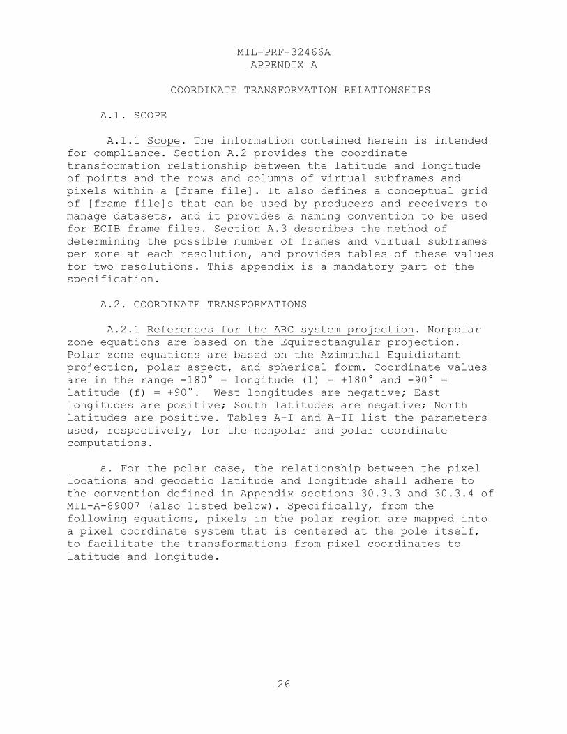
A.1.1 Scope. The information contained herein is intended
for compliance. Section A.2 provides the coordinate
transformation relationship between the latitude and longitude
of points and the rows and columns of virtual subframes and
pixels within a [frame file]. It also defines a conceptual grid
of [frame file]s that can be used by producers and receivers to
manage datasets, and it provides a naming convention to be used
for ECIB frame files. Section A.3 describes the method of
determining the possible number of frames and virtual subframes
per zone at each resolution, and provides tables of these values
for two resolutions. This appendix is a mandatory part of the
specification.
A.2. COORDINATE TRANSFORMATIONS
A.2.1 References for the ARC system projection. Nonpolar
zone equations are based on the Equirectangular projection.
Polar zone equations are based on the Azimuthal Equidistant
projection, polar aspect, and spherical form. Coordinate values
are in the range -180° = longitude (l) = +180° and -90° =
latitude (f) = +90°. West longitudes are negative; East
longitudes are positive; South latitudes are negative; North
latitudes are positive. Tables A-I and A-II list the parameters
used, respectively, for the nonpolar and polar coordinate
computations.
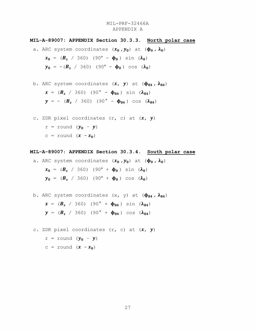
a. For the polar case, the relationship between the pixel
locations and geodetic latitude and longitude shall adhere to
the convention defined in Appendix sections 30.3.3 and 30.3.4 of
MIL-A-89007 (also listed below). Specifically, from the
following equations, pixels in the polar region are mapped into
a pixel coordinate system that is centered at the pole itself,
to facilitate the transformations from pixel coordinates to
latitude and longitude.
MIL-PRF-32466A
APPENDIX A
27
MIL-A-89007: APPENDIX Section 30.3.3. North polar case
a. ARC system coordinates (𝒙𝟎 ,𝒚𝟎) at (𝛟𝟎 , 𝛌𝟎)
𝒙𝟎 = (𝑩𝒔 / 360) (90° - 𝛟𝟎 ) sin (𝛌𝟎)
𝒚𝟎 = -(𝑩𝒔 / 360) (90° - 𝛟𝟎 ) cos (𝛌𝟎)
b. ARC system coordinates (𝒙, 𝒚) at (𝛟𝟖𝟒 , 𝛌𝟖𝟒)
𝒙 = (𝑩𝒔 / 360) (90° - 𝛟𝟖𝟒 ) sin (𝛌𝟖𝟒)
𝒚 = - (𝑩𝒔 / 360) (90° - 𝛟𝟖𝟒 ) cos (𝛌𝟖𝟒)
c. ZDR pixel coordinates (r, c) at (𝒙, 𝒚)
r = round (𝒚𝟎 – 𝒚)
c = round (𝒙 - 𝒙𝟎)
MIL-A-89007: APPENDIX Section 30.3.4. South polar case
a. ARC system coordinates (𝒙𝟎 ,𝒚𝟎) at (𝛟𝟎 , 𝛌𝟎)
𝒙𝟎 = (𝑩𝒔 / 360) (90° + 𝛟𝟎 ) sin (𝛌𝟎)
𝒚𝟎 = (𝑩𝒔 / 360) (90° + 𝛟𝟎 ) cos (𝛌𝟎)
b. ARC system coordinates (x, y) at (𝛟𝟖𝟒 , 𝛌𝟖𝟒)
𝒙 = (𝑩𝒔 / 360) (90° + 𝛟𝟖𝟒 ) sin (𝛌𝟖𝟒)
𝒚 = (𝑩𝒔 / 360) (90° + 𝛟𝟖𝟒 ) cos (𝛌𝟖𝟒)
c. ZDR pixel coordinates (r, c) at (𝒙, 𝒚)
r = round (𝒚𝟎 – 𝒚)
c = round (𝒙 - 𝒙𝟎)
MIL-PRF-32466A
APPENDIX A
28
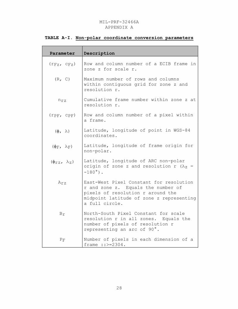
TABLE A-I. Non-polar coordinate conversion parameters
Parameter Description
(rFz, cFz) Row and column number of a ECIB frame in
zone z for scale r.
(R, C) Maximum number of rows and columns
within contiguous grid for zone z and
resolution r.
nrz Cumulative frame number within zone z at
resolution r.
(rPF, cPF) Row and column number of a pixel within
a frame.
(, λ) Latitude, longitude of point in WGS-84
coordinates.
(F, λF) Latitude, longitude of frame origin for
non-polar.
(rz, λz) Latitude, longitude of ARC non-polar
origin of zone z and resolution r (λz =
-180°).
Arz East-West Pixel Constant for resolution
r and zone z. Equals the number of
pixels of resolution r around the
midpoint latitude of zone z representing
a full circle.
Br North-South Pixel Constant for scale
resolution r in all zones. Equals the
number of pixels of resolution r
representing an arc of 90°.
PF Number of pixels in each dimension of a
frame ::>=2304.
MIL-PRF-32466A
APPENDIX A
29
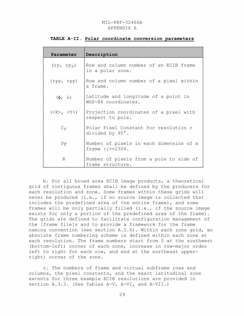
TABLE A-II. Polar coordinate conversion parameters
Parameter Description
(rF, cFz) Row and column number of an ECIB frame
in a polar zone.
(rPF, cPF) Row and column number of a pixel within
a frame.
(, λ) Latitude and longitude of a point in
WGS-84 coordinates.
(<X>, <Y>) Projection coordinates of a pixel with
respect to pole.
Cr Polar Pixel Constant for resolution r
divided by 90°.
PF Number of pixels in each dimension of a
frame ::>=2304.
R Number of pixels from a pole to side of
frame structure.
b. For all broad area ECIB image products, a theoretical
grid of contiguous frames shall be defined by the producers for
each resolution and zone. Some frames within these grids will
never be produced (i.e., if no source image is collected that
includes the predefined area of the entire frame), and some
frames will be only partially filled (i.e., if the source image
exists for only a portion of the predefined area of the frame).
The grids are defined to facilitate configuration management of
the [frame file]s and to provide a framework for the frame
naming convention (see section A.2.6). Within each zone grid, an
absolute frame numbering scheme is defined within each zone at
each resolution. The frame numbers start from 0 at the southwest
(bottom-left) corner of each zone, increase in row-major order
left to right for each row, and end at the northeast upper-
right) corner of the zone.
c. The numbers of frame and virtual subframe rows and
columns, the pixel constants, and the exact latitudinal zone
extents for three example ECIB resolutions are provided in
section A.3.3. (See Tables A-V, A-VI, and A-VII.)
MIL-PRF-32466A
APPENDIX A
30
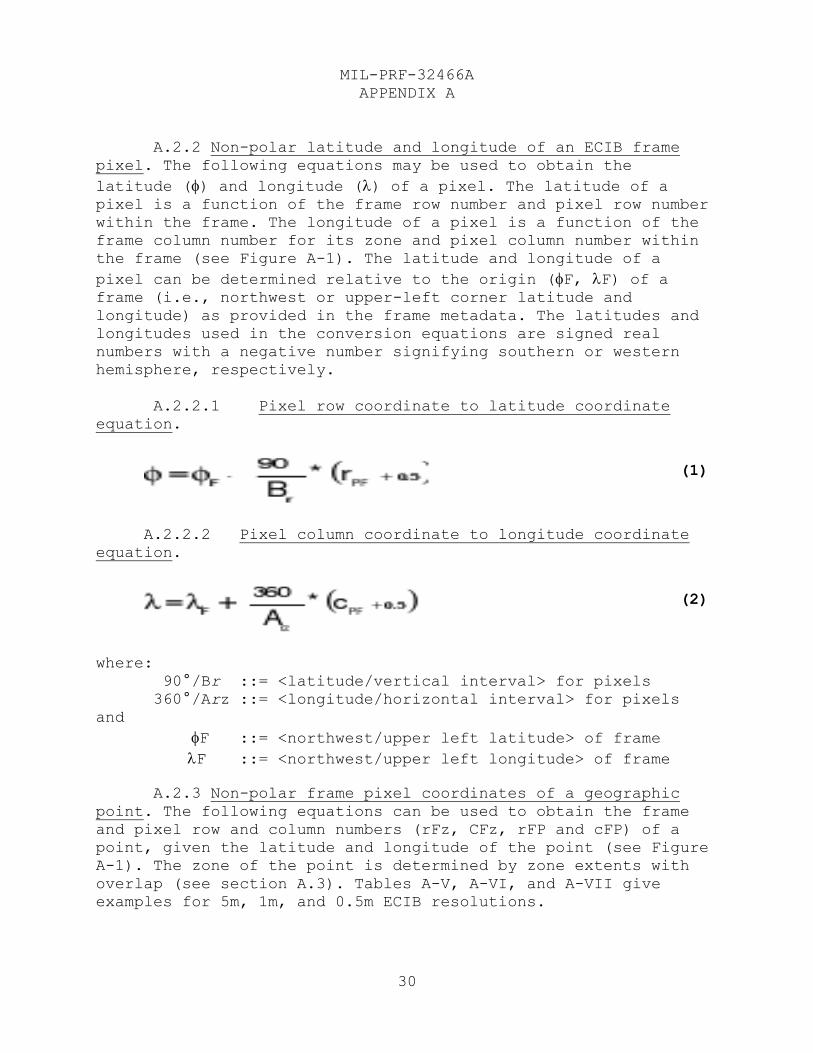
A.2.2 Non-polar latitude and longitude of an ECIB frame
pixel. The following equations may be used to obtain the
latitude () and longitude () of a pixel. The latitude of a pixel is a function of the frame row number and pixel row number
within the frame. The longitude of a pixel is a function of the
frame column number for its zone and pixel column number within
the frame (see Figure A-1). The latitude and longitude of a
pixel can be determined relative to the origin (F, F) of a frame (i.e., northwest or upper-left corner latitude and
longitude) as provided in the frame metadata. The latitudes and
longitudes used in the conversion equations are signed real
numbers with a negative number signifying southern or western
hemisphere, respectively.
A.2.2.1 Pixel row coordinate to latitude coordinate
equation.
A.2.2.2 Pixel column coordinate to longitude coordinate
equation.
where:
90°/Br ::= <latitude/vertical interval> for pixels
360°/Arz ::= <longitude/horizontal interval> for pixels
and
F ::= <northwest/upper left latitude> of frame
F ::= <northwest/upper left longitude> of frame
A.2.3 Non-polar frame pixel coordinates of a geographic
point. The following equations can be used to obtain the frame
and pixel row and column numbers (rFz, CFz, rFP and cFP) of a
point, given the latitude and longitude of the point (see Figure
A-1). The zone of the point is determined by zone extents with
overlap (see section A.3). Tables A-V, A-VI, and A-VII give
examples for 5m, 1m, and 0.5m ECIB resolutions.
(1)
(2)
MIL-PRF-32466A
APPENDIX A
31
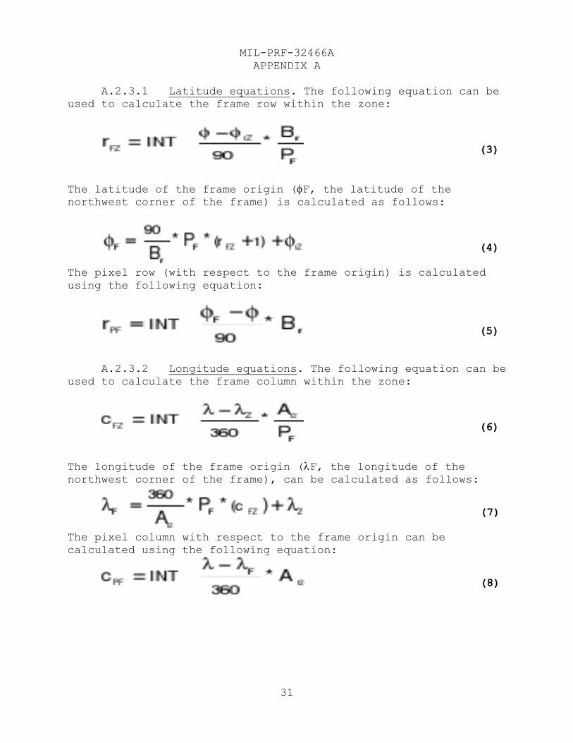
A.2.3.1 Latitude equations. The following equation can be
used to calculate the frame row within the zone:
The latitude of the frame origin (F, the latitude of the northwest corner of the frame) is calculated as follows:
The pixel row (with respect to the frame origin) is calculated
using the following equation:
A.2.3.2 Longitude equations. The following equation can be
used to calculate the frame column within the zone:
The longitude of the frame origin (F, the longitude of the northwest corner of the frame), can be calculated as follows:
The pixel column with respect to the frame origin can be
calculated using the following equation:
(3)
(4)
(5)
(6)
(7)
(8)
MIL-PRF-32466A
APPENDIX A
32
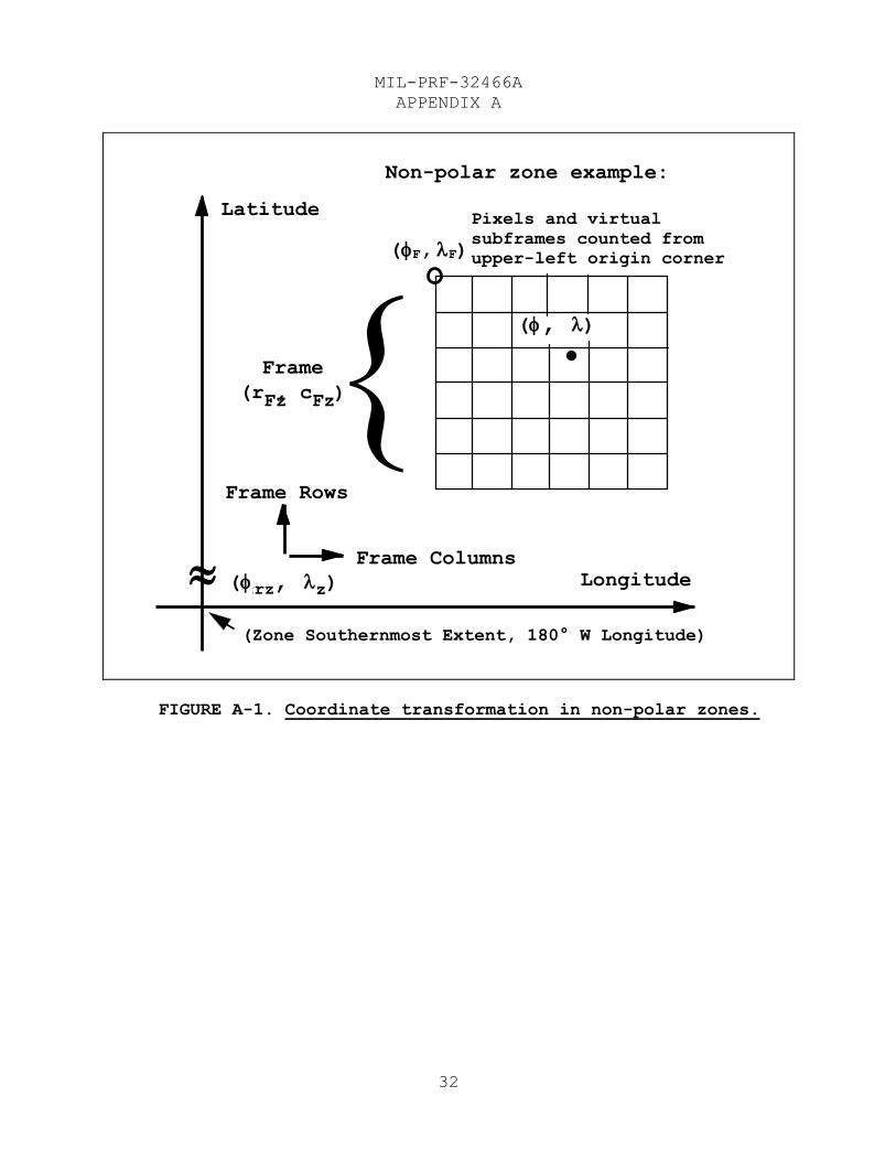
FIGURE A-1. Coordinate transformation in non-polar zones.
Non-polar zone example:
(Zone Southernmost Extent, 180° W Longitude)
( F , F )
Frame
(r Fz , c Fz )
Frame Columns
Frame Rows
Longitude
Latitude
( sz , z )
( , )
Pixels and virtual
subframes counted from
upper-left origin corner
rz
MIL-PRF-32466A
APPENDIX A
33
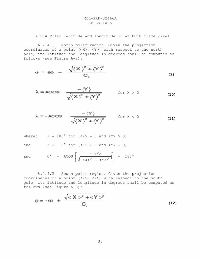
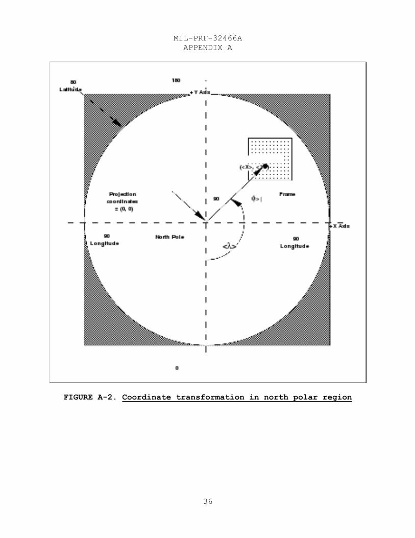
A.2.4 Polar latitude and longitude of an ECIB frame pixel.
A.2.4.1 North polar region. Given the projection
coordinates of a point (<X>, <Y>) with respect to the north
pole, its latitude and longitude in degrees shall be computed as
follows (see Figure A-2):
for X > 0
for X < 0
where: λ = 180° for [<X> = 0 and <Y> > 0]
and λ = 0° for [<X> = 0 and <Y> = 0]
and 0° = ACOS
– <Y>
<X>2 + <Y>2 = 180°
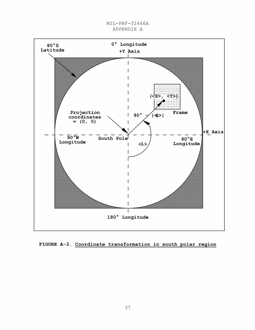
A.2.4.2 South polar region. Given the projection
coordinates of a point (<X>, <Y>) with respect to the south
pole, its latitude and longitude in degrees shall be computed as
follows (see Figure A-3):
(9)
(10)
(11)
(12)
MIL-PRF-32466A
APPENDIX A
34
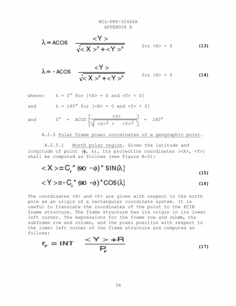
for <X> > 0
for <X> < 0
where: λ = 0° for [<X> = 0 and <Y> = 0]
and λ = 180° for [<X> = 0 and <Y> < 0]
and 0° = ACOS
<Y>
<X>2 + <Y>2 = 180°
A.2.5 Polar frame pixel coordinates of a geographic point.
A.2.5.1 North polar region. Given the latitude and
longitude of point (, λ), its projection coordinates (<X>, <Y>) shall be computed as follows (see Figure A-2):
The coordinates <X> and <Y> are given with respect to the north
pole as an origin of a rectangular coordinate system. It is
useful to translate the coordinates of the point to the ECIB
frame structure. The frame structure has its origin in its lower
left corner. The expressions for the frame row and column, the
subframe row and column, and the pixel position with respect to
the lower left corner of the frame structure are computed as
follows:
(13)
(14)
(15)
(16)
(17)
MIL-PRF-32466A
APPENDIX A
35
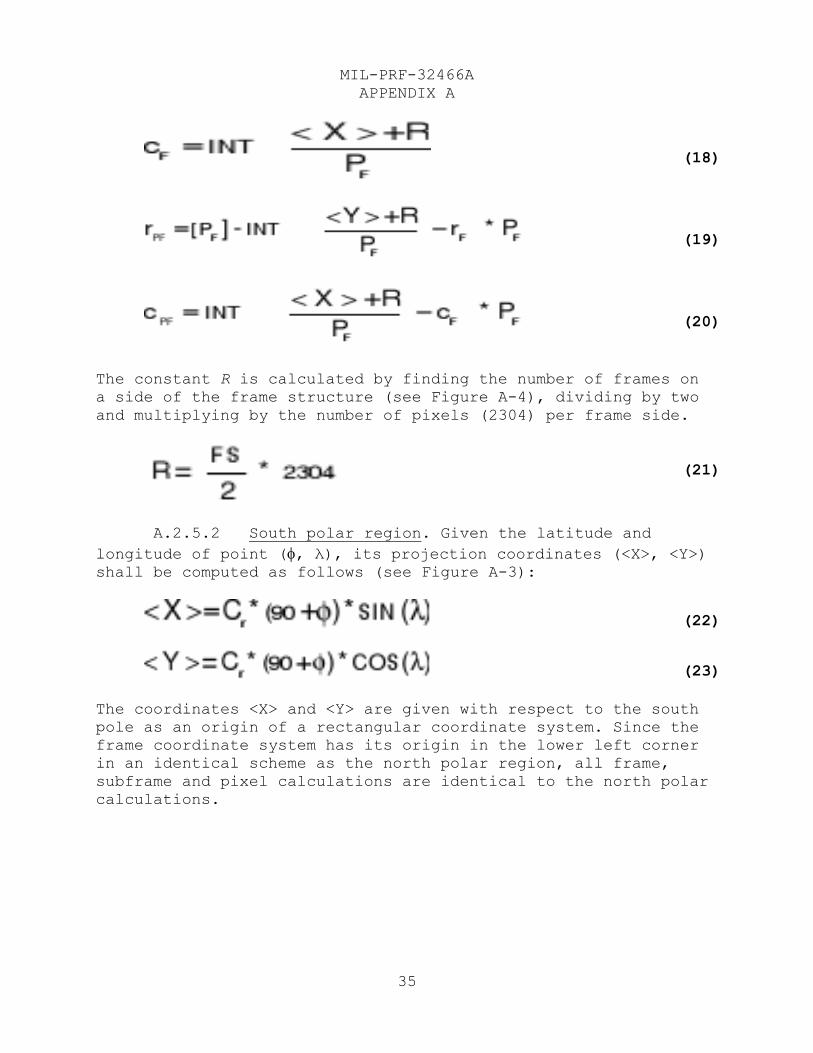
The constant R is calculated by finding the number of frames on
a side of the frame structure (see Figure A-4), dividing by two
and multiplying by the number of pixels (2304) per frame side.
A.2.5.2 South polar region. Given the latitude and
longitude of point (, λ), its projection coordinates (<X>, <Y>) shall be computed as follows (see Figure A-3):
The coordinates <X> and <Y> are given with respect to the south
pole as an origin of a rectangular coordinate system. Since the
frame coordinate system has its origin in the lower left corner
in an identical scheme as the north polar region, all frame,
subframe and pixel calculations are identical to the north polar
calculations.
(18)
(19)
(20)
(21)
(22)
(23)
MIL-PRF-32466A
APPENDIX A
36
FIGURE A-2. Coordinate transformation in north polar region
MIL-PRF-32466A
APPENDIX A
37
FIGURE A-3. Coordinate transformation in south polar region
80°S
Latitude
180° Longitude
90°E Longitude
0° Longitude
90°W Longitude
South Pole
Projection coordinates = (0, 0)
+Y Axis
+X Axis
(<X>, <Y>)
< >
90° - |< >| Frame
MIL-PRF-32466A
APPENDIX A
38
A.2.6 Frame conventions.
A.2.6.1 Frame naming convention. ECIB frame file names
shall conform to the form “ffffffffffvvvp.ccz”. (The contiguous
frame grid concept is depicted in figure A-4.) ECIB producers
are responsible for ensuring that [frame files] for all spatial
resolutions, zones, and revisions, have unique names.
a. The “ffffffffff” portion of the name shall be a ten-
digit radix 34 value that encodes the unique cumulative frame
number within a zone in base 34, nrz (see equations below), with
the right-most digit being the least significant position. The
radix 34 value incorporates the numbers 0 through 9 and letters
A through Z exclusive of the letters "I" and "O" as they are
easily confused with the numbers "1" and "0". For example, the
“ffffffffff” portion of the names would start with “0000000000,”
and proceed through “0000000009”. The next value would be
“000000000A” and the values would proceed through “000000000Z”,
“0000000010”, and so forth until “ZZZZZZZZZZ”. This allows
2,064,377,754,059,776 unique [frame file] names.
b. The “vvv” portion of the name shall be a successive
version number.
c. The “p” portion of the name shall be a radix 34 value that designates the producer code ID registered in MIL-STD-2411-
1.
d. The “cc” and “z” portions of the name extension shall
encode the data series code and the arc zone. Refer to Table II
for a complete list of zone limits and Table III for data series
codes.
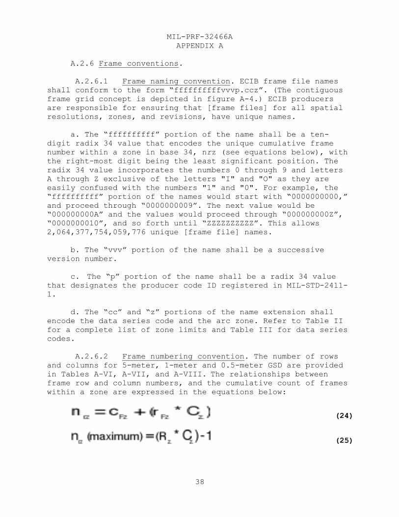
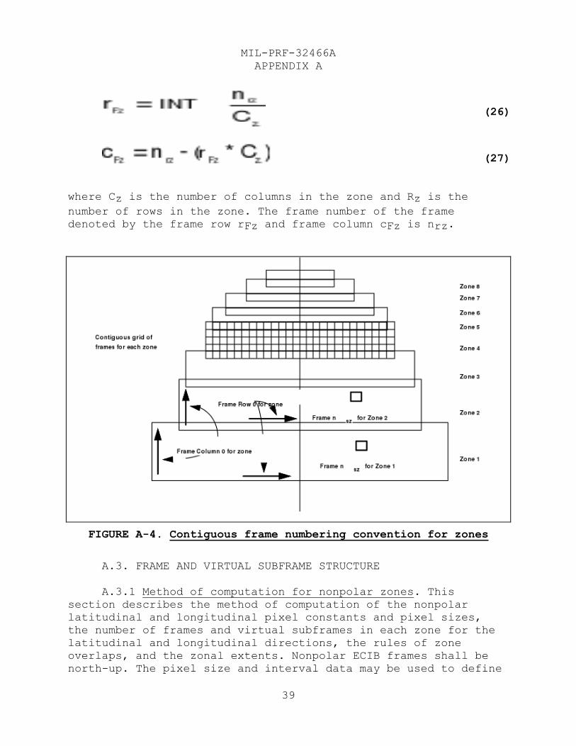
A.2.6.2 Frame numbering convention. The number of rows
and columns for 5-meter, 1-meter and 0.5-meter GSD are provided
in Tables A-VI, A-VII, and A-VIII. The relationships between
frame row and column numbers, and the cumulative count of frames
within a zone are expressed in the equations below:
(24)
(25)
MIL-PRF-32466A
APPENDIX A
39
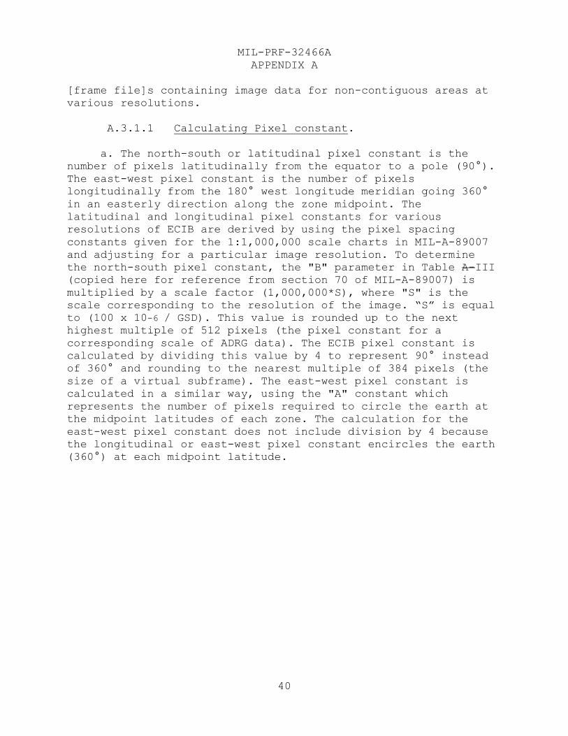
where Cz is the number of columns in the zone and Rz is the
number of rows in the zone. The frame number of the frame
denoted by the frame row rFz and frame column cFz is nrz.
FIGURE A-4. Contiguous frame numbering convention for zones
A.3. FRAME AND VIRTUAL SUBFRAME STRUCTURE
A.3.1 Method of computation for nonpolar zones. This
section describes the method of computation of the nonpolar
latitudinal and longitudinal pixel constants and pixel sizes,
the number of frames and virtual subframes in each zone for the
latitudinal and longitudinal directions, the rules of zone
overlaps, and the zonal extents. Nonpolar ECIB frames shall be
north-up. The pixel size and interval data may be used to define
(26)
(27)
MIL-PRF-32466A
APPENDIX A
40
[frame file]s containing image data for non-contiguous areas at
various resolutions.
A.3.1.1 Calculating Pixel constant.
a. The north-south or latitudinal pixel constant is the
number of pixels latitudinally from the equator to a pole (90°).
The east-west pixel constant is the number of pixels
longitudinally from the 180° west longitude meridian going 360°
in an easterly direction along the zone midpoint. The
latitudinal and longitudinal pixel constants for various
resolutions of ECIB are derived by using the pixel spacing
constants given for the 1:1,000,000 scale charts in MIL-A-89007
and adjusting for a particular image resolution. To determine
the north-south pixel constant, the "B" parameter in Table A-III
(copied here for reference from section 70 of MIL-A-89007) is
multiplied by a scale factor (1,000,000*S), where "S" is the
scale corresponding to the resolution of the image. “S” is equal
to (100 x 10-6 / GSD). This value is rounded up to the next
highest multiple of 512 pixels (the pixel constant for a
corresponding scale of ADRG data). The ECIB pixel constant is
calculated by dividing this value by 4 to represent 90° instead
of 360° and rounding to the nearest multiple of 384 pixels (the
size of a virtual subframe). The east-west pixel constant is
calculated in a similar way, using the "A" constant which
represents the number of pixels required to circle the earth at
the midpoint latitudes of each zone. The calculation for the
east-west pixel constant does not include division by 4 because
the longitudinal or east-west pixel constant encircles the earth
(360°) at each midpoint latitude.
MIL-PRF-32466A
APPENDIX A
41
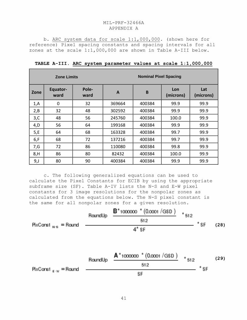
b. ARC system data for scale 1:1,000,000. (shown here for
reference) Pixel spacing constants and spacing intervals for all
zones at the scale 1:1,000,000 are shown in Table A-III below.
TABLE A-III. ARC system parameter values at scale 1:1,000,000
Zone Limits Nominal Pixel Spacing
Zone Equator-
ward Pole- ward
A B Lon
(microns) Lat
(microns)
1,A 0 32 369664 400384 99.9 99.9
2,B 32 48 302592 400384 99.9 99.9
3,C 48 56 245760 400384 100.0 99.9
4,D 56 64 199168 400384 99.9 99.9
5,E 64 68 163328 400384 99.7 99.9
6,F 68 72 137216 400384 99.7 99.9
7,G 72 86 110080 400384 99.8 99.9
8,H 86 80 82432 400384 100.0 99.9
9,J 80 90 400384 400384 99.9 99.9
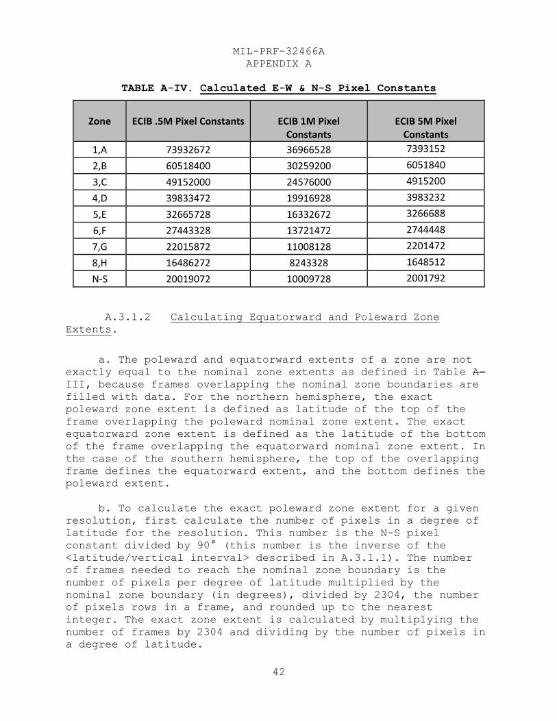
c. The following generalized equations can be used to
calculate the Pixel Constants for ECIB by using the appropriate
subframe size (SF). Table A-IV lists the N-S and E-W pixel
constants for 3 image resolutions for the nonpolar zones as
calculated from the equations below. The N-S pixel constant is
the same for all nonpolar zones for a given resolution.
(29)
(28)
Zone Limits Nominal Pixel Spacing
MIL-PRF-32466A
APPENDIX A
42
TABLE A-IV. Calculated E-W & N-S Pixel Constants
Zone
ECIB .5M Pixel Constants
ECIB 1M Pixel
Constants
ECIB 5M Pixel
Constants
1,A 73932672 36966528 7393152
2,B 60518400 30259200 6051840
3,C 49152000 24576000 4915200
4,D 39833472 19916928 3983232
5,E 32665728 16332672 3266688
6,F 27443328 13721472 2744448
7,G 22015872 11008128 2201472
8,H 16486272 8243328 1648512
N-S 20019072 10009728 2001792
A.3.1.2 Calculating Equatorward and Poleward Zone
Extents.
a. The poleward and equatorward extents of a zone are not
exactly equal to the nominal zone extents as defined in Table A-
III, because frames overlapping the nominal zone boundaries are
filled with data. For the northern hemisphere, the exact
poleward zone extent is defined as latitude of the top of the
frame overlapping the poleward nominal zone extent. The exact
equatorward zone extent is defined as the latitude of the bottom
of the frame overlapping the equatorward nominal zone extent. In
the case of the southern hemisphere, the top of the overlapping
frame defines the equatorward extent, and the bottom defines the
poleward extent.
b. To calculate the exact poleward zone extent for a given
resolution, first calculate the number of pixels in a degree of
latitude for the resolution. This number is the N-S pixel
constant divided by 90° (this number is the inverse of the
<latitude/vertical interval> described in A.3.1.1). The number
of frames needed to reach the nominal zone boundary is the
number of pixels per degree of latitude multiplied by the
nominal zone boundary (in degrees), divided by 2304, the number
of pixels rows in a frame, and rounded up to the nearest
integer. The exact zone extent is calculated by multiplying the
number of frames by 2304 and dividing by the number of pixels in
a degree of latitude.

MIL-PRF-32466A
APPENDIX A
43
c. To calculate the exact equatorward zone extent for a
given resolution, again calculate the number of frames needed to
reach the nominal zone boundary (the equatorward boundary in
this case) by using the same method described in the previous
paragraph. For the equatorward case, round the number of frames
down to the nearest integer. Again, the exact zone extent is
calculated by multiplying the number of frames by 2304 and
dividing by the number of pixels in a degree of latitude.
d. The maximum stretch or shrink of frame pixels within a
zone may be computed as the difference between the cosine of the
resulting zonal extents latitude and the cosine of the midpoint
latitude, and then dividing by the cosine of the midpoint
latitude.
A.3.1.3 Calculating Latitudinal Frames and Subframes.
The number of latitudinal frames and subframes in a zone for a
given resolution can be computed by using the exact poleward and
equatorward zone extents and the number of pixels per degree of
latitude (as calculated in A.3.1.2). The number of latitudinal
frames is the difference (in degrees) between the exact poleward
zone extent and exact equatorward zone extent, multiplied by
number of pixels per degree, divided by 2304, the number of
pixel rows per frame, then rounded to the nearest whole number.
Multiplying the number of framerows by 6 will yield the number
of subframes for that resolution and zone.
A.3.1.4 Calculating Longitudinal frames and subframes.
The number of longitudinal frames and subframes is computed by
determining the number of subframes to reach around the earth
along a parallel at the zone midpoint. The east-west pixel
constant is divided by 384 pixels to determine the number of
subframes. The results are divided by 6 and rounded up to obtain
the number of frame columns.
A.3.2 Additional computations for the polar zones. The
computations for the polar zones are described in the following
sections.
A.3.2.1 Polar pixel constant. For ECIB, the polar pixel
constant is derived from the N-S pixel constant for a particular
resolution product. The ECIB value for the polar pixel constant
is calculated by multiplying the N-S pixel constant for the
resolution by the ratio 20/90 (degrees), rounding to the nearest
multiple of 768 (to insure that the number of virtual subframes

MIL-PRF-32466A
APPENDIX A
44
about the pole can be equal in each direction), then multiplying
by the ratio 90/20 (degrees).
A.3.2.2 Polar frames and virtual subframes. The number
of the polar virtual subframes in each dimension (symmetric) is
computed by multiplying the polar pixel constant by the ratio
20°/90°, dividing by 384 pixels per virtual subframe, and then
adding four subframes to the result. The four subframes are
added to allow for overlap all around the earth. The number of
frames is determined by dividing this value by 6 virtual
subframes per frame, but rounding up to the next odd number of
frames. (This ensures that a symmetric number of frames can be
centered at the pole.) All polar frames are fully populated
provided that data exists in the areas.
A.3.2.3 Polar zone extents. The poleward extent of the
polar zones is exactly 90°. The equatorward extent of the polar
regions is less than 80° (i.e., it overlaps the data from zones
8 and H) but the exact extent varies. This is because the frames
are not aligned with the latitudinal bands around the earth (see
Figures A-2 and A-3).
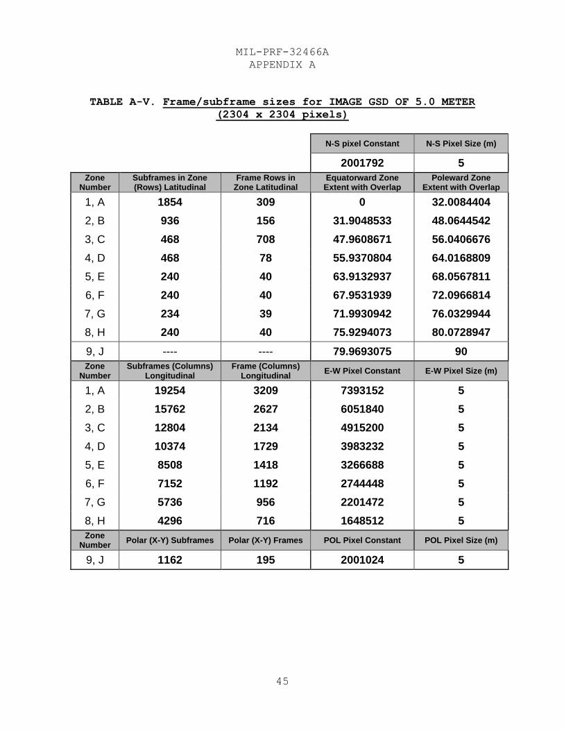
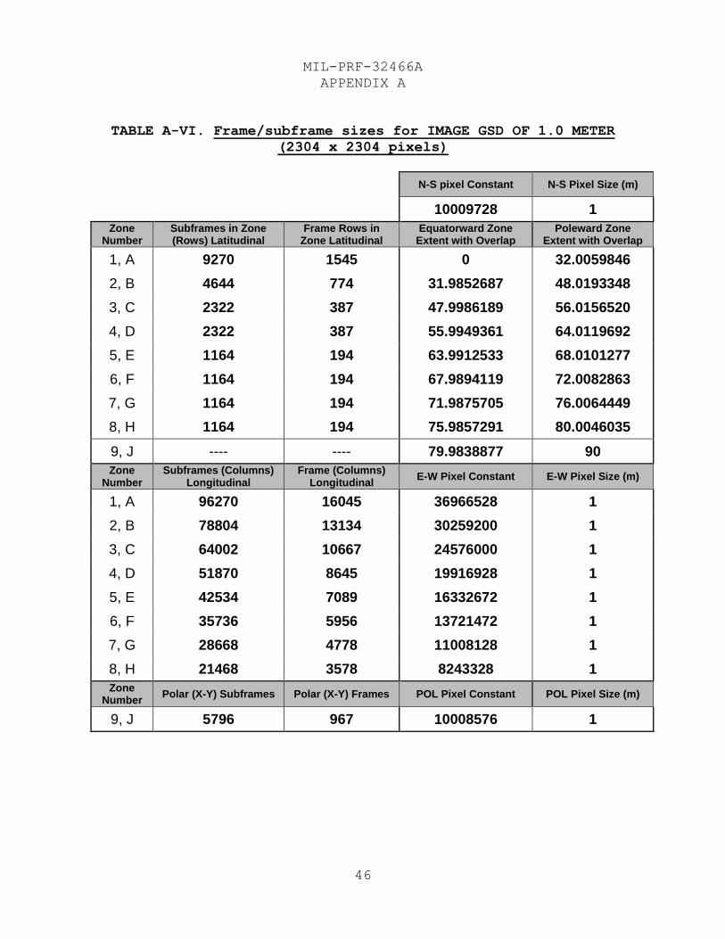
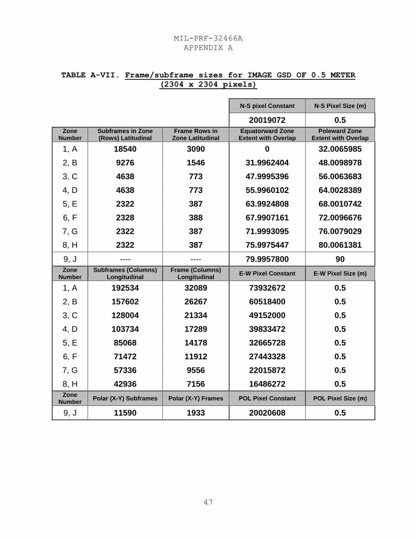
A.3.3 Tabular data for frame and virtual subframe
structure. Results of computations defined above for the
latitudinal and longitudinal data are enumerated in Tables A-V,
A-VI, and A-VII for three resolutions of ECIB source data. The
same values can be computed for any arbitrary resolution image,
using the methodology outlined above in A.3.1 and A.3.2. This
would allow developing ECIB [frame files] for various
resolution, non-contiguous images.
MIL-PRF-32466A
APPENDIX A
45
TABLE A-V. Frame/subframe sizes for IMAGE GSD OF 5.0 METER
(2304 x 2304 pixels)
N-S pixel Constant N-S Pixel Size (m)
2001792 5
Zone Number
Subframes in Zone (Rows) Latitudinal
Frame Rows in Zone Latitudinal
Equatorward Zone Extent with Overlap
Poleward Zone Extent with Overlap
1, A 1854 309 0 32.0084404
2, B 936 156 31.9048533 48.0644542
3, C 468 708 47.9608671 56.0406676
4, D 468 78 55.9370804 64.0168809
5, E 240 40 63.9132937 68.0567811
6, F 240 40 67.9531939 72.0966814
7, G 234 39 71.9930942 76.0329944
8, H 240 40 75.9294073 80.0728947
9, J ---- ---- 79.9693075 90
Zone Number
Subframes (Columns) Longitudinal
Frame (Columns) Longitudinal
E-W Pixel Constant E-W Pixel Size (m)
1, A 19254 3209 7393152 5
2, B 15762 2627 6051840 5
3, C 12804 2134 4915200 5
4, D 10374 1729 3983232 5
5, E 8508 1418 3266688 5
6, F 7152 1192 2744448 5
7, G 5736 956 2201472 5
8, H 4296 716 1648512 5
Zone Number
Polar (X-Y) Subframes Polar (X-Y) Frames POL Pixel Constant POL Pixel Size (m)
9, J 1162 195 2001024 5
MIL-PRF-32466A
APPENDIX A
46
TABLE A-VI. Frame/subframe sizes for IMAGE GSD OF 1.0 METER
(2304 x 2304 pixels)
N-S pixel Constant N-S Pixel Size (m)
10009728 1
Zone Number
Subframes in Zone (Rows) Latitudinal
Frame Rows in Zone Latitudinal
Equatorward Zone Extent with Overlap
Poleward Zone Extent with Overlap
1, A 9270 1545 0 32.0059846
2, B 4644 774 31.9852687 48.0193348
3, C 2322 387 47.9986189 56.0156520
4, D 2322 387 55.9949361 64.0119692
5, E 1164 194 63.9912533 68.0101277
6, F 1164 194 67.9894119 72.0082863
7, G 1164 194 71.9875705 76.0064449
8, H 1164 194 75.9857291 80.0046035
9, J ---- ---- 79.9838877 90
Zone Number
Subframes (Columns) Longitudinal
Frame (Columns) Longitudinal
E-W Pixel Constant E-W Pixel Size (m)
1, A 96270 16045 36966528 1
2, B 78804 13134 30259200 1
3, C 64002 10667 24576000 1
4, D 51870 8645 19916928 1
5, E 42534 7089 16332672 1
6, F 35736 5956 13721472 1
7, G 28668 4778 11008128 1
8, H 21468 3578 8243328 1
Zone Number
Polar (X-Y) Subframes Polar (X-Y) Frames POL Pixel Constant POL Pixel Size (m)
9, J 5796 967 10008576 1
MIL-PRF-32466A
APPENDIX A
47
TABLE A-VII. Frame/subframe sizes for IMAGE GSD OF 0.5 METER
(2304 x 2304 pixels)
N-S pixel Constant N-S Pixel Size (m)
20019072 0.5
Zone Number
Subframes in Zone (Rows) Latitudinal
Frame Rows in Zone Latitudinal
Equatorward Zone Extent with Overlap
Poleward Zone Extent with Overlap
1, A 18540 3090 0 32.0065985
2, B 9276 1546 31.9962404 48.0098978
3, C 4638 773 47.9995396 56.0063683
4, D 4638 773 55.9960102 64.0028389
5, E 2322 387 63.9924808 68.0010742
6, F 2328 388 67.9907161 72.0096676
7, G 2322 387 71.9993095 76.0079029
8, H 2322 387 75.9975447 80.0061381
9, J ---- ---- 79.9957800 90
Zone Number
Subframes (Columns) Longitudinal
Frame (Columns) Longitudinal
E-W Pixel Constant E-W Pixel Size (m)
1, A 192534 32089 73932672 0.5
2, B 157602 26267 60518400 0.5
3, C 128004 21334 49152000 0.5
4, D 103734 17289 39833472 0.5
5, E 85068 14178 32665728 0.5
6, F 71472 11912 27443328 0.5
7, G 57336 9556 22015872 0.5
8, H 42936 7156 16486272 0.5
Zone Number
Polar (X-Y) Subframes Polar (X-Y) Frames POL Pixel Constant POL Pixel Size (m)
9, J 11590 1933 20020608 0.5
MIL-PRF-32466A
APPENDIX B
48
STORAGE REQUIREMENTS
B.1. SCOPE
B.1.1 Scope. The information contained herein is intended
for compliance. This appendix provides information about the
sizes of the sections of a frame file and provides a typical
example with binary and decimal or logical values for that
example. This appendix is a mandatory part of the specification.
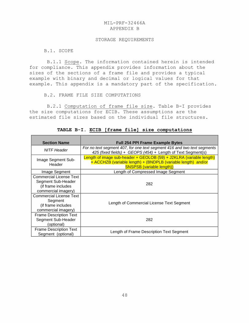
B.2. FRAME FILE SIZE COMPUTATIONS
B.2.1 Computation of frame file size. Table B-I provides
the size computations for ECIB. These assumptions are the
estimated file sizes based on the individual file structures.
TABLE B-I. ECIB [frame file] size computations
Section Name Full 254 PPI Frame Example Bytes
NITF Header For no text segment 407, for one text segment 416 and two text segments
425 (fixed fields) + GEOPS (454) + Length of Text Segment(s)
Image Segment Sub-Header
Length of image sub-header + GEOLOB (59) + J2KLRA (variable length) + ACCHZB (variable length) + (BNDPLB (variable length) and/or
SNSPSB (variable length))
Image Segment Length of Compressed Image Segment
Commercial License Text Segment Sub-Header
(if frame includes commercial imagery)
282
Commercial License Text Segment
(if frame includes commercial imagery)
Length of Commercial License Text Segment
Frame Description Text Segment Sub-Header
(optional) 282
Frame Description Text Segment (optional)
Length of Frame Description Text Segment
MIL-PRF-32466A
APPENDIX C
49
ECIB DATA CONTENT SPECIFICS
C.1. SCOPE
C.1.1 Scope. This appendix lists ECIB file content
specifics, attributes, and data types. This appendix is a
mandatory part of the specification, and compliance testing will
include tests for the presence of required information content
specified herein.
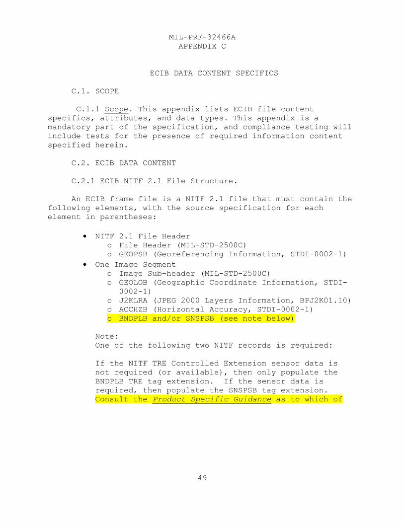
C.2. ECIB DATA CONTENT
C.2.1 ECIB NITF 2.1 File Structure.
An ECIB frame file is a NITF 2.1 file that must contain the
following elements, with the source specification for each
element in parentheses:
NITF 2.1 File Header
o File Header (MIL-STD-2500C)
o GEOPSB (Georeferencing Information, STDI-0002-1)
One Image Segment
o Image Sub-header (MIL-STD-2500C)
o GEOLOB (Geographic Coordinate Information, STDI-
0002-1)
o J2KLRA (JPEG 2000 Layers Information, BPJ2K01.10)
o ACCHZB (Horizontal Accuracy, STDI-0002-1)
o BNDPLB and/or SNSPSB (see note below)
Note:
One of the following two NITF records is required:
If the NITF TRE Controlled Extension sensor data is
not required (or available), then only populate the
BNDPLB TRE tag extension. If the sensor data is
required, then populate the SNSPSB tag extension.
Consult the Product Specific Guidance as to which of
MIL-PRF-32466A
APPENDIX C
50
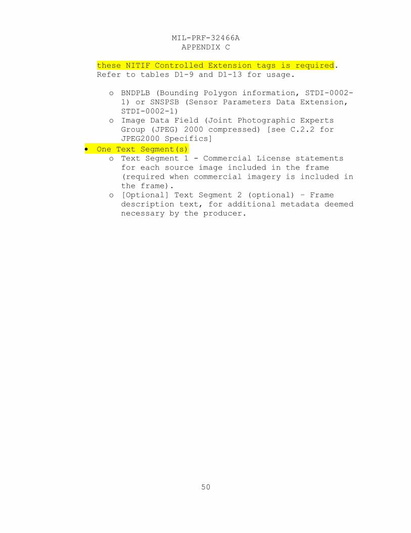
these NITIF Controlled Extension tags is required.
Refer to tables D1-9 and D1-13 for usage.
o BNDPLB (Bounding Polygon information, STDI-0002-
1) or SNSPSB (Sensor Parameters Data Extension,
STDI-0002-1)
o Image Data Field (Joint Photographic Experts
Group (JPEG) 2000 compressed) [see C.2.2 for
JPEG2000 Specifics]
One Text Segment(s)
o Text Segment 1 - Commercial License statements
for each source image included in the frame
(required when commercial imagery is included in
the frame).
o [Optional] Text Segment 2 (optional) – Frame
description text, for additional metadata deemed
necessary by the producer.
MIL-PRF-32466A
APPENDIX C
51
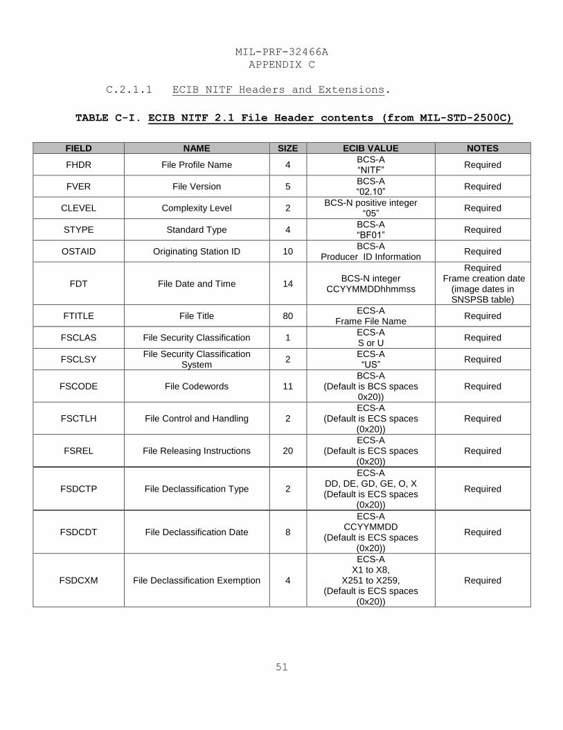
C.2.1.1 ECIB NITF Headers and Extensions.
TABLE C-I. ECIB NITF 2.1 File Header contents (from MIL-STD-2500C)
FIELD NAME SIZE ECIB VALUE NOTES
FHDR File Profile Name 4 BCS-A “NITF”
Required
FVER File Version 5 BCS-A “02.10”
Required
CLEVEL Complexity Level 2 BCS-N positive integer
“05” Required
STYPE Standard Type 4 BCS-A “BF01”
Required
OSTAID Originating Station ID 10 BCS-A
Producer ID Information Required
FDT File Date and Time 14 BCS-N integer
CCYYMMDDhhmmss
Required Frame creation date
(image dates in SNSPSB table)
FTITLE File Title 80 ECS-A
Frame File Name Required
FSCLAS File Security Classification 1 ECS-A S or U
Required
FSCLSY File Security Classification
System 2
ECS-A “US”
Required
FSCODE File Codewords 11 BCS-A
(Default is BCS spaces 0x20))
Required
FSCTLH File Control and Handling 2 ECS-A
(Default is ECS spaces (0x20))
Required
FSREL File Releasing Instructions 20 ECS-A
(Default is ECS spaces (0x20))
Required
FSDCTP File Declassification Type 2
ECS-A DD, DE, GD, GE, O, X (Default is ECS spaces
(0x20))
Required
FSDCDT File Declassification Date 8
ECS-A CCYYMMDD
(Default is ECS spaces (0x20))
Required
FSDCXM File Declassification Exemption 4
ECS-A X1 to X8,
X251 to X259, (Default is ECS spaces
(0x20))
Required
MIL-PRF-32466A
APPENDIX C
52
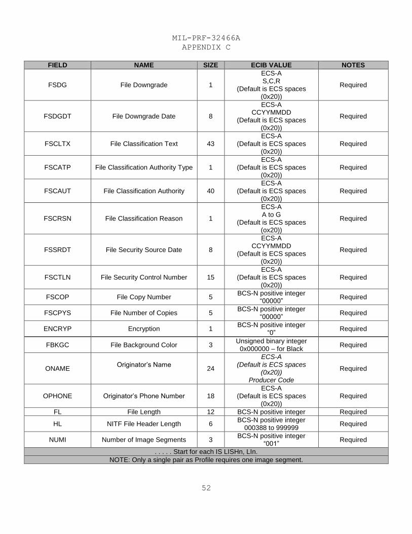
FIELD NAME SIZE ECIB VALUE NOTES
FSDG File Downgrade 1
ECS-A S,C,R
(Default is ECS spaces (0x20))
Required
FSDGDT File Downgrade Date 8
ECS-A CCYYMMDD
(Default is ECS spaces (0x20))
Required
FSCLTX File Classification Text 43 ECS-A
(Default is ECS spaces (0x20))
Required
FSCATP File Classification Authority Type 1 ECS-A
(Default is ECS spaces (0x20))
Required
FSCAUT File Classification Authority 40 ECS-A
(Default is ECS spaces (0x20))
Required
FSCRSN File Classification Reason 1
ECS-A A to G
(Default is ECS spaces (ox20))
Required
FSSRDT File Security Source Date 8
ECS-A CCYYMMDD
(Default is ECS spaces (0x20))
Required
FSCTLN File Security Control Number 15 ECS-A
(Default is ECS spaces (0x20))
Required
FSCOP File Copy Number 5 BCS-N positive integer
“00000” Required
FSCPYS File Number of Copies 5 BCS-N positive integer
“00000” Required
ENCRYP Encryption 1 BCS-N positive integer
“0” Required
FBKGC File Background Color 3 Unsigned binary integer
0x000000 – for Black Required
ONAME Originator’s Name
24
ECS-A (Default is ECS spaces
(0x20)) Producer Code
Required
OPHONE Originator’s Phone Number 18 ECS-A
(Default is ECS spaces (0x20))
Required
FL File Length 12 BCS-N positive integer Required
HL NITF File Header Length 6 BCS-N positive integer
000388 to 999999 Required
NUMI Number of Image Segments 3 BCS-N positive integer
“001” Required
. . . . . Start for each IS LISHn, LIn.
NOTE: Only a single pair as Profile requires one image segment.
MIL-PRF-32466A
APPENDIX C
53
FIELD NAME SIZE ECIB VALUE NOTES
LISH001 Length of nth Image Sub-header 6 BCS-N positive integer
001076 to 999998
Required, Per Appendix B,
there will be a single image in the file.
LI001 Length of nth Image Segment 10 BCS-N positive integer See Notes to less than
0000524228799
Required, Per Appendix B,
there will be a single image in the file.
Note: Based on Appendix B this
value will likely be less than 1,000,000
bytes.
. . . . End for each IS LISHn, LIn; the number of loop repetitions is the value specified in the NUMI field.
NUMS Number of Graphic Segments 3 BCS-N positive integer
“000” Required
NUMX Reserved for Future Use 3 BCS-N positive integer
“000” Required
NUMT Number of Text Segments 3 BCS-N positive integer
“001” to “002” or “000” if no license required
Required
. . . . . Start for each TS LTSHn, LTn.
NOTE: Profile includes conditional commercial license text segment and optional frame description text segment
LTSHn Length of nth text sub-header 4 BCS-N positive integer
“0282” Conditional - If CI in frame, must include.
LTn Length of nth text segment 5 BCS-N positive integer
00001 to 99998 Conditional - If CI in frame, must include.
. . . . End for each TS LTSHn, LTn; the number of loop repetitions is the value specified in the NUMT field.
NUMDES Number of Data Extension
Segments 3
BCS-N positive integer “000”
Required
NUMRES Number of Reserved Extension
Segments 3
BCS-N positive integer “000”
Required
UDHDL User Defined Header Data
Length 5
BCS-N positive integer “00000”
Required
XHDL Extended Header Data Length 5 BCS-N positive integer
“00457”
Required; there will be a single TRE in the header of
the file.
XHDLOFL Extended Header Data Overflow 3 BCS-N positive integer
“000”
Required; there will be no use of TRE Overflow.
XHD Extended Header Data 454 TRE
Required; the total length is
based on the CETAG length 6, the
CEL length 5 and the GEOPSB length
443 bytes.
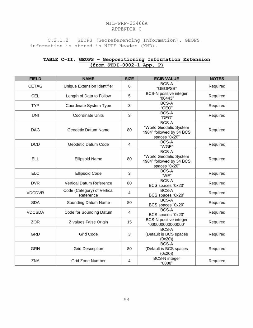
MIL-PRF-32466A
APPENDIX C
54
C.2.1.2 GEOPS (Georeferencing Information). GEOPS
information is stored in NITF Header (XHD).
TABLE C-II. GEOPS – Geopositioning Information Extension
(from STDI-0002-1 App. P)
FIELD NAME SIZE ECIB VALUE NOTES
CETAG Unique Extension Identifier 6 BCS-A
“GEOPSB” Required
CEL Length of Data to Follow 5 BCS-N positive integer
“00443” Required
TYP Coordinate System Type 3 BCS-A “GEO”
Required
UNI Coordinate Units 3 BCS-A “DEG”
Required
DAG Geodetic Datum Name 80
BCS-A “World Geodetic System
1984” followed by 54 BCS spaces “0x20”
Required
DCD Geodetic Datum Code 4 BCS-A “WGE”
Required
ELL Ellipsoid Name 80
BCS-A “World Geodetic System
1984” followed by 54 BCS spaces “0x20”
Required
ELC Ellipsoid Code 3 BCS-A “WE”
Required
DVR Vertical Datum Reference 80 BCS-A
BCS spaces “0x20” Required
VDCDVR Code (Category) of Vertical
Reference 4
BCS-A BCS spaces “0x20”
Required
SDA Sounding Datum Name 80 BCS-A
BCS spaces “0x20” Required
VDCSDA Code for Sounding Datum 4 BCS-A
BCS spaces “0x20” Required
ZOR Z values False Origin 15 BCS-N positive integer “000000000000000”
Required
GRD Grid Code 3 BCS-A
(Default is BCS spaces (0x20))
Required
GRN Grid Description 80 BCS-A
(Default is BCS spaces (0x20))
Required
ZNA Grid Zone Number 4 BCS-N integer
“0000” Required
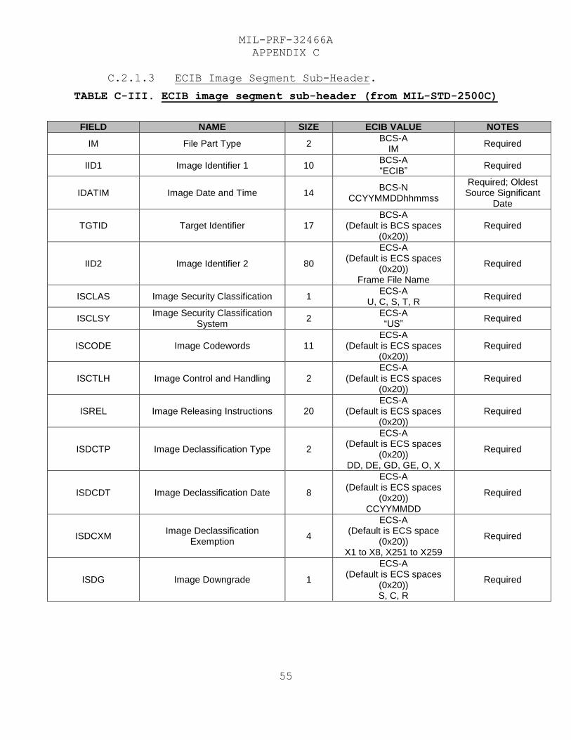
MIL-PRF-32466A
APPENDIX C
55
C.2.1.3 ECIB Image Segment Sub-Header.
TABLE C-III. ECIB image segment sub-header (from MIL-STD-2500C)
FIELD NAME SIZE ECIB VALUE NOTES
IM File Part Type 2 BCS-A
IM Required
IID1 Image Identifier 1 10 BCS-A “ECIB”
Required
IDATIM Image Date and Time 14 BCS-N
CCYYMMDDhhmmss
Required; Oldest Source Significant
Date
TGTID Target Identifier 17 BCS-A
(Default is BCS spaces (0x20))
Required
IID2 Image Identifier 2 80
ECS-A (Default is ECS spaces
(0x20)) Frame File Name
Required
ISCLAS Image Security Classification 1 ECS-A
U, C, S, T, R Required
ISCLSY Image Security Classification
System 2
ECS-A “US”
Required
ISCODE Image Codewords 11 ECS-A
(Default is ECS spaces (0x20))
Required
ISCTLH Image Control and Handling 2 ECS-A
(Default is ECS spaces (0x20))
Required
ISREL Image Releasing Instructions 20 ECS-A
(Default is ECS spaces (0x20))
Required
ISDCTP Image Declassification Type 2
ECS-A (Default is ECS spaces
(0x20)) DD, DE, GD, GE, O, X
Required
ISDCDT Image Declassification Date 8
ECS-A (Default is ECS spaces
(0x20)) CCYYMMDD
Required
ISDCXM Image Declassification
Exemption 4
ECS-A (Default is ECS space
(0x20)) X1 to X8, X251 to X259
Required
ISDG Image Downgrade 1
ECS-A (Default is ECS spaces
(0x20)) S, C, R
Required
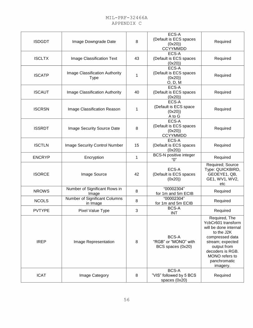
MIL-PRF-32466A
APPENDIX C
56
ISDGDT Image Downgrade Date 8
ECS-A (Default is ECS spaces
(0x20)) CCYYMMDD
Required
ISCLTX Image Classification Text 43 ECS-A
(Default is ECS spaces (0x20))
Required
ISCATP Image Classification Authority
Type 1
ECS-A (Default is ECS spaces
(0x20)) O, D, M
Required
ISCAUT Image Classification Authority 40 ECS-A
(Default is ECS spaces (0x20))
Required
ISCRSN Image Classification Reason 1
ECS-A (Default is ECS space
(0x20)) A to G
Required
ISSRDT Image Security Source Date 8
ECS-A (Default is ECS spaces
(0x20)) CCYYMMDD
Required
ISCTLN Image Security Control Number 15 ECS-A
(Default is ECS spaces (0x20))
Required
ENCRYP Encryption 1 BCS-N positive integer
“0” Required
ISORCE Image Source 42 ECS-A
(Default is ECS spaces (0x20))
Required; Source Type: QUICKBIRD,
GEOEYE1, QB, GE1, WV1, WV2,
etc
NROWS Number of Significant Rows in
Image 8
“00002304” for 1m and 5m ECIB
Required
NCOLS Number of Significant Columns
in Image 8
“00002304” for 1m and 5m ECIB
Required
PVTYPE Pixel Value Type 3 BCS-A
INT Required
IREP Image Representation 8 BCS-A
“RGB” or “MONO” with BCS spaces (0x20)
Required, The YcbCr601 transform will be done internal
to the J2K compressed data stream; expected
output from decoders is RGB. MONO refers to panchromatic
imagery.
ICAT Image Category 8 BCS-A
”VIS” followed by 5 BCS spaces (0x20)
Required
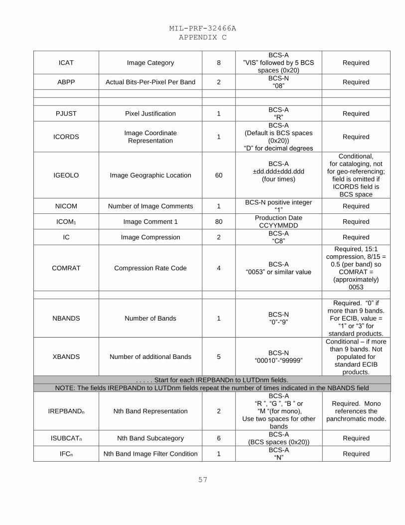
MIL-PRF-32466A
APPENDIX C
57
ICAT Image Category 8 BCS-A
”VIS” followed by 5 BCS spaces (0x20)
Required
ABPP Actual Bits-Per-Pixel Per Band 2 BCS-N
“08” Required
PJUST Pixel Justification 1 BCS-A
“R” Required
ICORDS Image Coordinate
Representation 1
BCS-A (Default is BCS spaces
(0x20)) “D” for decimal degrees
Required
IGEOLO Image Geographic Location 60
BCS-A ±dd.ddd±ddd.ddd
(four times)
Conditional, for cataloging, not
for geo-referencing; field is omitted if ICORDS field is
BCS space
NICOM Number of Image Comments 1 BCS-N positive integer
“1” Required
ICOM1 Image Comment 1 80 Production Date
CCYYMMDD Required
IC Image Compression 2 BCS-A
“C8” Required
COMRAT Compression Rate Code 4 BCS-A
“0053” or similar value
Required, 15:1 compression, 8/15 =
0.5 (per band) so COMRAT =
(approximately) 0053
NBANDS Number of Bands 1 BCS-N “0”-“9”
Required. “0” if more than 9 bands. For ECIB, value =
“1” or “3” for standard products.
XBANDS Number of additional Bands 5 BCS-N
“00010”-“99999”
Conditional – if more than 9 bands. Not
populated for standard ECIB
products.
. . . . . Start for each IREPBANDn to LUTDnm fields.
NOTE: The fields IREPBANDn to LUTDnm fields repeat the number of times indicated in the NBANDS field
IREPBANDn Nth Band Representation 2
BCS-A “R ”, “G ”, “B ” or “M “(for mono),
Use two spaces for other bands
Required. Mono references the
panchromatic mode.
ISUBCATn Nth Band Subcategory 6 BCS-A
(BCS spaces (0x20)) Required
IFCn Nth Band Image Filter Condition 1 BCS-A
“N” Required
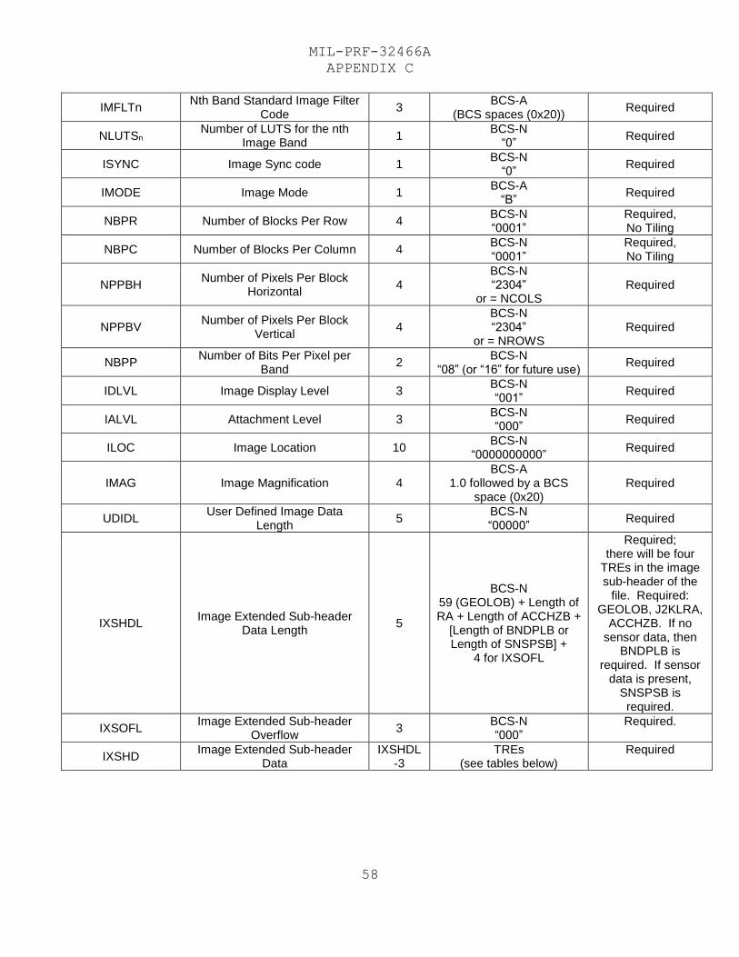
MIL-PRF-32466A
APPENDIX C
58
IMFLTn Nth Band Standard Image Filter
Code 3
BCS-A (BCS spaces (0x20))
Required
NLUTSn Number of LUTS for the nth
Image Band 1
BCS-N “0”
Required
ISYNC Image Sync code 1 BCS-N
“0” Required
IMODE Image Mode 1 BCS-A
“B” Required
NBPR Number of Blocks Per Row 4 BCS-N “0001”
Required, No Tiling
NBPC Number of Blocks Per Column 4 BCS-N “0001”
Required, No Tiling
NPPBH Number of Pixels Per Block
Horizontal 4
BCS-N “2304”
or = NCOLS Required
NPPBV Number of Pixels Per Block
Vertical 4
BCS-N “2304”
or = NROWS Required
NBPP Number of Bits Per Pixel per
Band 2
BCS-N “08” (or “16” for future use)
Required
IDLVL Image Display Level 3 BCS-N “001”
Required
IALVL Attachment Level 3 BCS-N “000”
Required
ILOC Image Location 10 BCS-N
“0000000000” Required
IMAG Image Magnification 4 BCS-A
1.0 followed by a BCS space (0x20)
Required
UDIDL User Defined Image Data
Length 5
BCS-N “00000”
Required
IXSHDL Image Extended Sub-header
Data Length 5
BCS-N 59 (GEOLOB) + Length of RA + Length of ACCHZB +
[Length of BNDPLB or Length of SNSPSB] +
4 for IXSOFL
Required; there will be four
TREs in the image sub-header of the
file. Required: GEOLOB, J2KLRA,
ACCHZB. If no sensor data, then
BNDPLB is required. If sensor
data is present, SNSPSB is required.
IXSOFL Image Extended Sub-header
Overflow 3
BCS-N “000”
Required.
IXSHD Image Extended Sub-header
Data IXSHDL
-3 TREs
(see tables below) Required
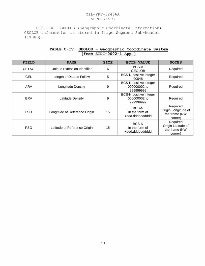
MIL-PRF-32466A
APPENDIX C
59
C.2.1.4 GEOLOB (Geographic Coordinate Information).
GEOLOB information is stored in Image Segment Sub-header
(IXSHD).
TABLE C-IV. GEOLOB – Geographic Coordinate System
(from STDI-0002-1 App.)
FIELD NAME SIZE ECIB VALUE NOTES
CETAG Unique Extension Identifier 6 BCS-A
GEOLOB Required
CEL Length of Data to Follow 5 BCS-N positive integer
00048 Required
ARV Longitude Density 9 BCS-N positive integer
000000002 to 999999999
Required
BRV Latitude Density 9 BCS-N positive integer
000000002 to 999999999
Required
LSO Longitude of Reference Origin 15 BCS-N
In the form of +ddd.dddddddddd
Required Origin Longitude of
the frame (NW corner)
PSO Latitude of Reference Origin 15 BCS-N
In the form of +ddd.dddddddddd
Required Origin Latitude of the frame (NW
corner)
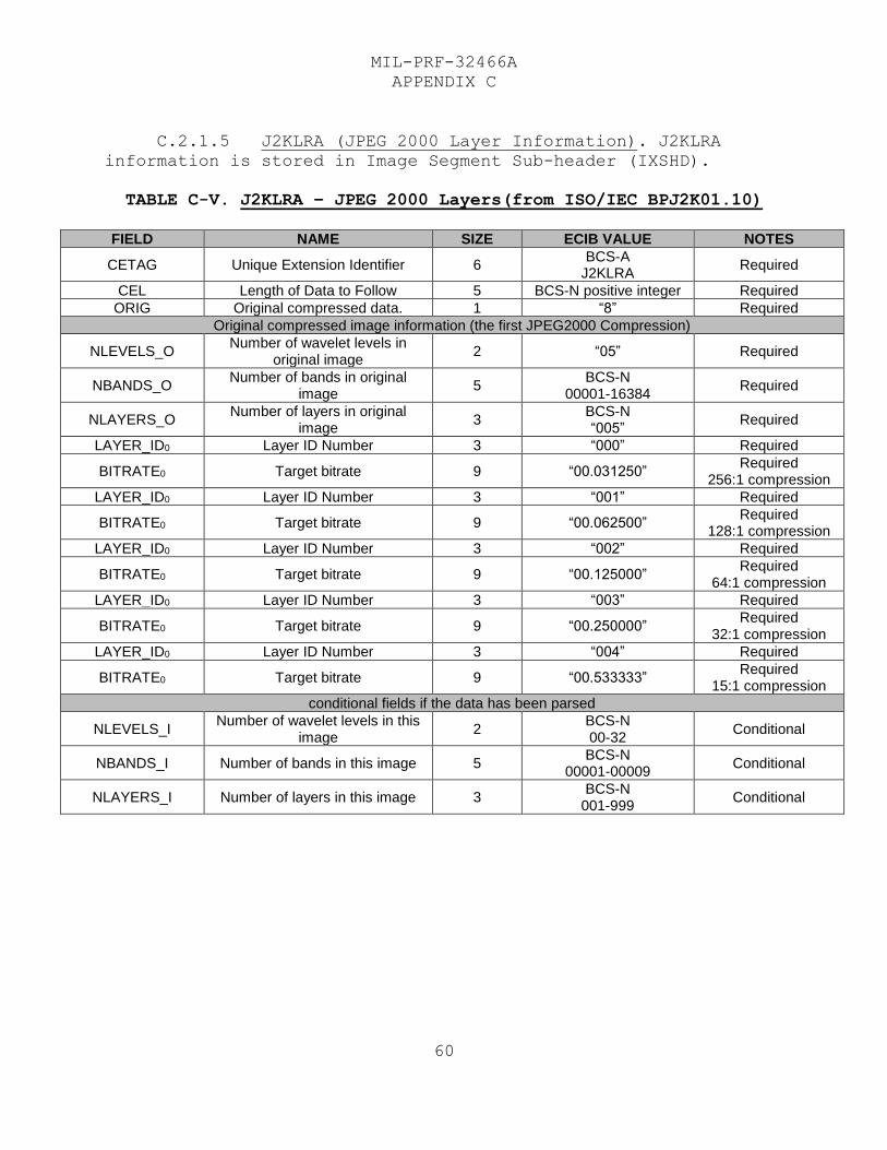
MIL-PRF-32466A
APPENDIX C
60
C.2.1.5 J2KLRA (JPEG 2000 Layer Information). J2KLRA
information is stored in Image Segment Sub-header (IXSHD).
TABLE C-V. J2KLRA – JPEG 2000 Layers(from ISO/IEC BPJ2K01.10)
FIELD NAME SIZE ECIB VALUE NOTES
CETAG Unique Extension Identifier 6 BCS-A
J2KLRA Required
CEL Length of Data to Follow 5 BCS-N positive integer Required
ORIG Original compressed data. 1 “8” Required
Original compressed image information (the first JPEG2000 Compression)
NLEVELS_O Number of wavelet levels in
original image 2 “05” Required
NBANDS_O Number of bands in original
image 5
BCS-N 00001-16384
Required
NLAYERS_O Number of layers in original
image 3
BCS-N “005”
Required
LAYER_ID0 Layer ID Number 3 “000” Required
BITRATE0 Target bitrate 9 “00.031250” Required
256:1 compression
LAYER_ID0 Layer ID Number 3 “001” Required
BITRATE0 Target bitrate 9 “00.062500” Required
128:1 compression
LAYER_ID0 Layer ID Number 3 “002” Required
BITRATE0 Target bitrate 9 “00.125000” Required
64:1 compression
LAYER_ID0 Layer ID Number 3 “003” Required
BITRATE0 Target bitrate 9 “00.250000” Required
32:1 compression
LAYER_ID0 Layer ID Number 3 “004” Required
BITRATE0 Target bitrate 9 “00.533333” Required
15:1 compression
conditional fields if the data has been parsed
NLEVELS_I Number of wavelet levels in this
image 2
BCS-N 00-32
Conditional
NBANDS_I Number of bands in this image 5 BCS-N
00001-00009 Conditional
NLAYERS_I Number of layers in this image 3 BCS-N
001-999 Conditional
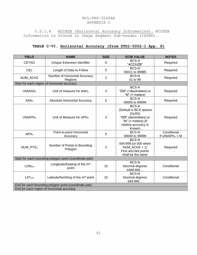
MIL-PRF-32466A
APPENDIX C
61
C.2.1.6 ACCHZB (Horizontal Accuracy Information). ACCHZB
information is stored in Image Segment Sub-header (IXSHD).
TABLE C-VI. Horizontal Accuracy (from STDI-0002-1 App. P)
FIELD NAME SIZE ECIB VALUE NOTES
CETAG Unique Extension Identifier 6 BCS-A
“ACCHZB” Required
CEL Length of Data to Follow 5 BCS-N
00011 to 99985 Required
NUM_ACHZ Number of Horizontal Accuracy
Regions 2
BCS-N 01 to 99
Required
Start for each region of horizontal accuracy
UNIAAHn Unit of measure for AAHn 3 BCS-A
“DM” (=decimeters) or “M” (= meters)
Required
AAHn Absolute Horizontal Accuracy 5 BCS-N
00000 to 99999 Required
UNIAPHn Unit of Measure for APHn 3
BCS-A (Default is BCS spaces
(0x20)) “DM” (decimeters) or
“M” (= meters) (if relative accuracy is
known)
Required
APHn Point-to-point Horizontal
Accuracy 5
BCS-N 00000 to 99999
Conditional If UNIAPHn = M
NUM_PTSn Number of Points in Bounding
Polygon 3
BCS-N 004-999 (or 000 when
NUM_ACHZ = 1) First and last points shall be the same
Required
Start for each bounding polygon point (coordinate pair)
LONnm Longitude/Easting of the mth
point 15
BCS-N Decimal degrees
±ddd.ddd… Conditional
LATnm Latitude/Northing of the mth point 15 BCS-N
Decimal degrees ±dd.ddd…
Conditional
End for each bounding polygon point (coordinate pair)
End for each region of horizontal accuracy
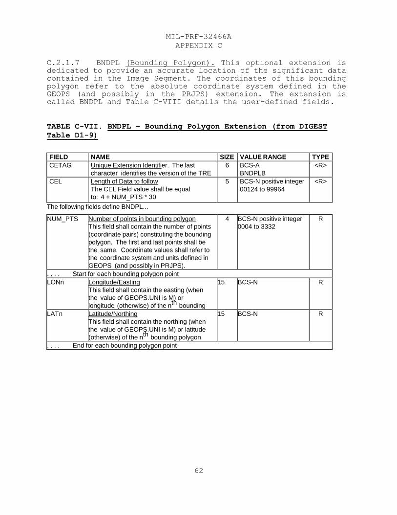
MIL-PRF-32466A
APPENDIX C
62
C.2.1.7 BNDPL (Bounding Polygon). This optional extension is dedicated to provide an accurate location of the significant data contained in the Image Segment. The coordinates of this bounding polygon refer to the absolute coordinate system defined in the GEOPS (and possibly in the PRJPS) extension. The extension is called BNDPL and Table C-VIII details the user-defined fields.
TABLE C-VII. BNDPL – Bounding Polygon Extension (from DIGEST
Table D1-9)
FIELD NAME SIZE VALUE RANGE TYPE CETAG Unique Extension Identifier. The last
character identifies the version of the TRE
6 BCS-A
BNDPLB
<R>
CEL Length of Data to follow
The CEL Field value shall be equal
to: 4 + NUM_PTS * 30
5 BCS-N positive integer
00124 to 99964
<R>
The following fields define BNDPL...
NUM_PTS Number of points in bounding polygon
This field shall contain the number of points
(coordinate pairs) constituting the bounding
polygon. The first and last points shall be
the same. Coordinate values shall refer to
the coordinate system and units defined in
GEOPS (and possibly in PRJPS).
4 BCS-N positive integer
0004 to 3332
R
. . . . Start for each bounding polygon point
LONn Longitude/Easting
This field shall contain the easting (when
the value of GEOPS.UNI is M) or
longitude (otherwise) of the nth bounding
polygon point.
15 BCS-N R
LATn Latitude/Northing
This field shall contain the northing (when
the value of GEOPS.UNI is M) or latitude
(otherwise) of the nth bounding polygon
point.
15 BCS-N R
. . . . End for each bounding polygon point
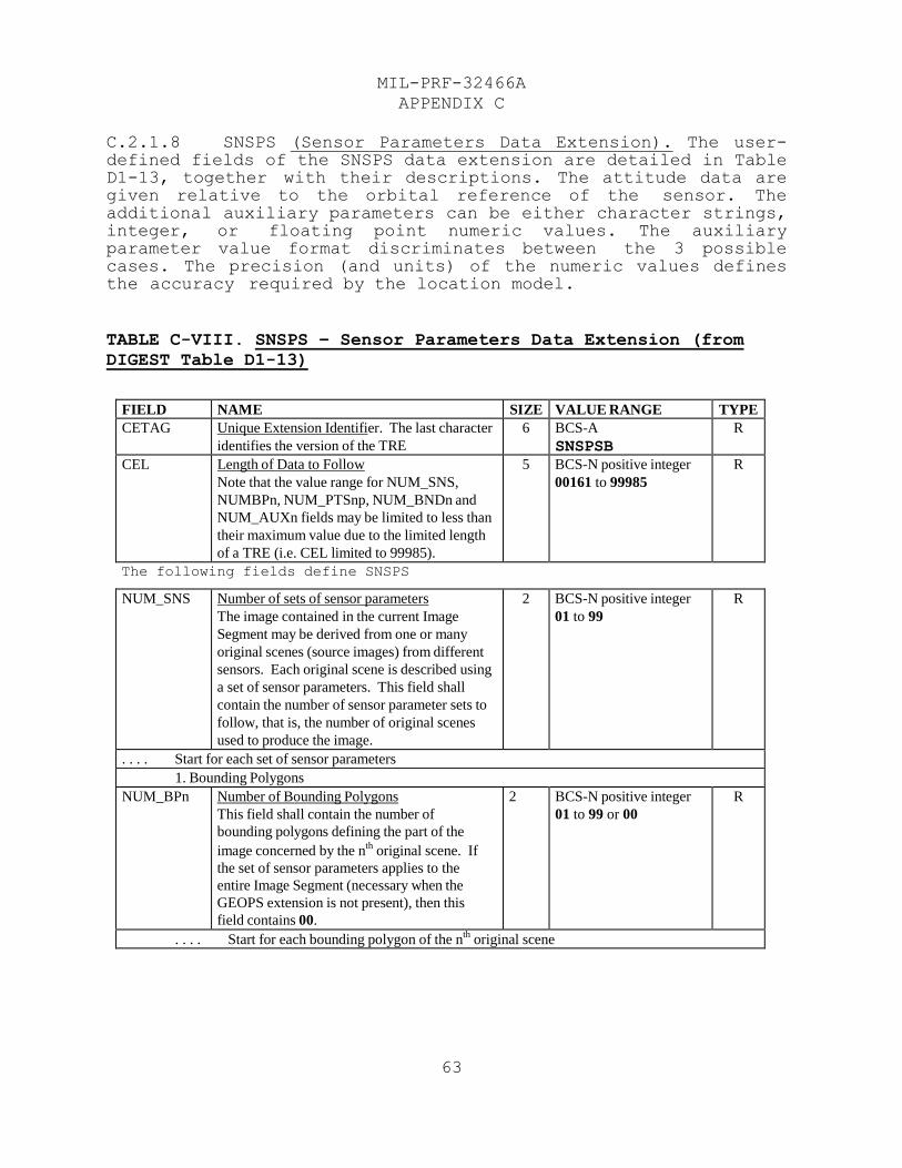
MIL-PRF-32466A
APPENDIX C
63
C.2.1.8 SNSPS (Sensor Parameters Data Extension). The user-defined fields of the SNSPS data extension are detailed in Table D1-13, together with their descriptions. The attitude data are given relative to the orbital reference of the sensor. The additional auxiliary parameters can be either character strings, integer, or floating point numeric values. The auxiliary parameter value format discriminates between the 3 possible cases. The precision (and units) of the numeric values defines the accuracy required by the location model.
TABLE C-VIII. SNSPS – Sensor Parameters Data Extension (from
DIGEST Table D1-13)
FIELD NAME SIZE VALUE RANGE TYPE CETAG Unique Extension Identifier. The last character
identifies the version of the TRE 6 BCS-A
SNSPSB R
CEL Length of Data to Follow
Note that the value range for NUM_SNS,
NUMBPn, NUM_PTSnp, NUM_BNDn and
NUM_AUXn fields may be limited to less than
their maximum value due to the limited length
of a TRE (i.e. CEL limited to 99985).
5 BCS-N positive integer
00161 to 99985 R
The following fields define SNSPS
NUM_SNS Number of sets of sensor parameters
The image contained in the current Image
Segment may be derived from one or many
original scenes (source images) from different
sensors. Each original scene is described using
a set of sensor parameters. This field shall
contain the number of sensor parameter sets to
follow, that is, the number of original scenes
used to produce the image.
2 BCS-N positive integer
01 to 99 R
. . . . Start for each set of sensor parameters 1. Bounding Polygons
NUM_BPn Number of Bounding Polygons
This field shall contain the number of
bounding polygons defining the part of the
image concerned by the nth
original scene. If
the set of sensor parameters applies to the
entire Image Segment (necessary when the
GEOPS extension is not present), then this
field contains 00.
2 BCS-N positive integer
01 to 99 or 00 R
. . . . Start for each bounding polygon of the nth
original scene

MIL-PRF-32466A
APPENDIX C
64
NUM_PTSnp Number of Points in the pth
Bounding Polygon
This field is required when the value of
NUM_BPn is greater than 00, and shall be
omitted otherwise. When present, this field
shall contain the number of points (coordinate
pairs) that are used to define the pth
bounding
polygon of the nth
original scene. Coordinate
values shall refer to the coordinate system and
units defined in GEOPS (and possibly in
PRJPS). First and last points shall be the
same.
3 BCS-N positive integer
004 to 999 C
(R)
FIELD NAME SIZE VALUE RANGE TYPE . . . . Start for each point (coordinate pair) of the p
th bounding polygon
LONnpm Longitude/Easting
This field is required when the value of
NUM_BPn is greater than 00, and shall be
omitted otherwise. When present, this field
shall contain the easting (when the value of
GEOPS.UNI is M) or the longitude (otherwise)
of the mth
point of the pth
bounding polygon.
15 BCS-N C
(R)
LATnpm Latitude/Northing
This field is required when the value of
NUM_BPn is greater than 00, and shall be
omitted otherwise. When present, this field
shall contain the northing (when the value of
GEOPS.UNI is M) or the latitude (otherwise)
of the mth
point of the pth
bounding polygon.
15 BCS-N C
(R)
. . . . End for each point (coordinate pair) of the pth
bounding polygon . . . . End for each bounding polygon of the n
th original scene
2. Identification of the bands of the nth
original scene at capture stage NUM_BNDn Number of Bands
This field shall contain the number of bands of
the nth
original scene.
NOTE: The band description of the original
scene may differ from the band description of
the transmitted image especially in case of
radiometric treatment (e.g., infra-red band
changed into red band, RGB image changed
into color-coded image, ...). When there is a
one-to-one correspondence between the
original scene and the image, the band
description order in the SNSPS extension shall
be consistent with the band description order in
the Image Subheader.
2 BCS-N positive integer
01 to 99 R
. . . . Start for each band of the nth
original scene BIDnp Original Scene Band Identification
This field shall contain an identification of the
pth
band of the nth
original scene.
5 BCS-A R
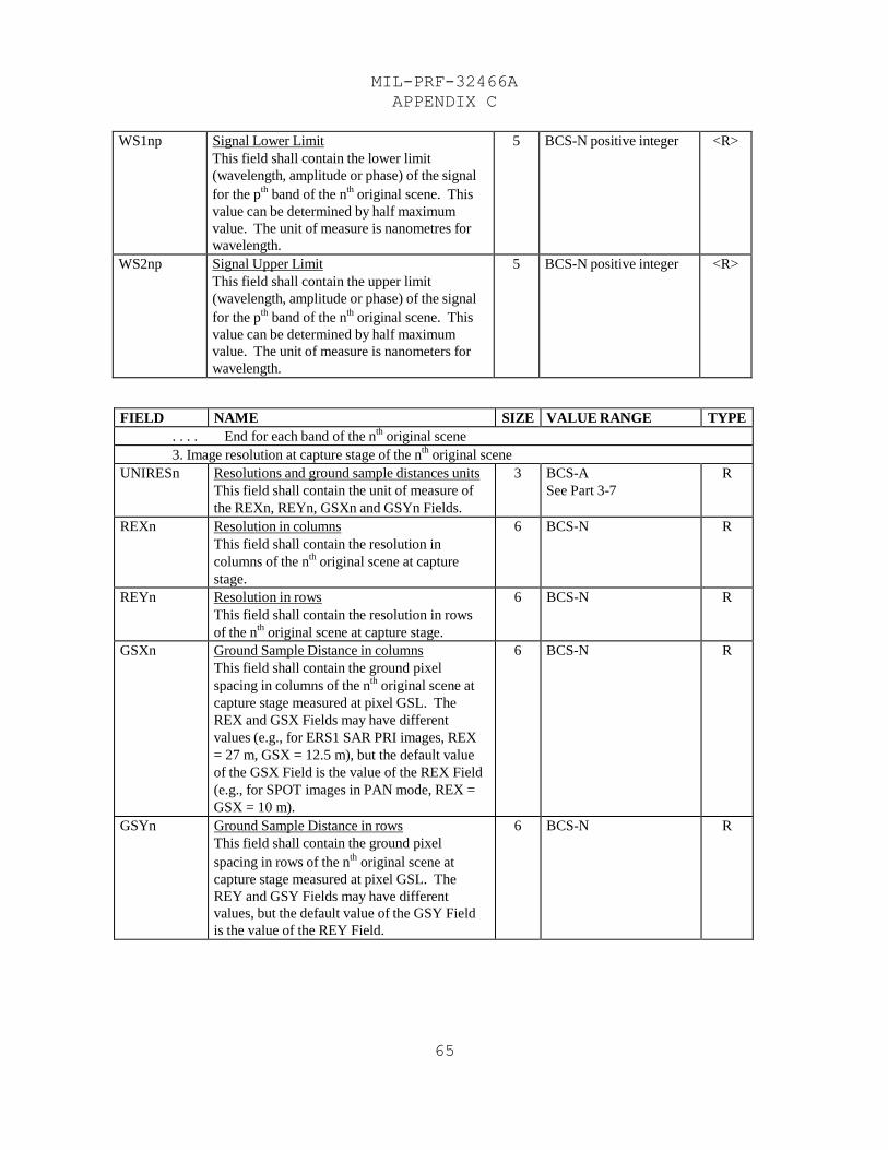
MIL-PRF-32466A
APPENDIX C
65
WS1np Signal Lower Limit
This field shall contain the lower limit
(wavelength, amplitude or phase) of the signal
for the pth
band of the nth
original scene. This
value can be determined by half maximum
value. The unit of measure is nanometres for
wavelength.
5 BCS-N positive integer <R>
WS2np Signal Upper Limit
This field shall contain the upper limit
(wavelength, amplitude or phase) of the signal
for the pth
band of the nth
original scene. This
value can be determined by half maximum
value. The unit of measure is nanometers for
wavelength.
5 BCS-N positive integer <R>
FIELD NAME SIZE VALUE RANGE TYPE . . . . End for each band of the n
th original scene
3. Image resolution at capture stage of the nth
original scene UNIRESn Resolutions and ground sample distances units
This field shall contain the unit of measure of
the REXn, REYn, GSXn and GSYn Fields.
3 BCS-A
See Part 3-7 R
REXn Resolution in columns
This field shall contain the resolution in
columns of the nth
original scene at capture
stage.
6 BCS-N R
REYn Resolution in rows
This field shall contain the resolution in rows
of the nth
original scene at capture stage.
6 BCS-N R
GSXn Ground Sample Distance in columns
This field shall contain the ground pixel
spacing in columns of the nth
original scene at
capture stage measured at pixel GSL. The
REX and GSX Fields may have different
values (e.g., for ERS1 SAR PRI images, REX
= 27 m, GSX = 12.5 m), but the default value
of the GSX Field is the value of the REX Field
(e.g., for SPOT images in PAN mode, REX =
GSX = 10 m).
6 BCS-N R
GSYn Ground Sample Distance in rows
This field shall contain the ground pixel
spacing in rows of the nth
original scene at
capture stage measured at pixel GSL. The
REY and GSY Fields may have different
values, but the default value of the GSY Field
is the value of the REY Field.
6 BCS-N R
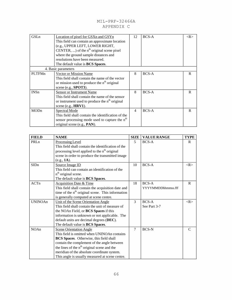
MIL-PRF-32466A
APPENDIX C
66
GSLn Location of pixel for GSXn and GSYn
This field can contain an approximate location
(e.g., UPPER LEFT, LOWER RIGHT,
CENTER, ...) of the nth
original scene pixel
where the ground sample distances and
resolutions have been measured.
The default value is BCS Spaces.
12 BCS-A <R>
4. Basic parameters PLTFMn Vector or Mission Name
This field shall contain the name of the vector
or mission used to produce the nth
original
scene (e.g., SPOT3).
8 BCS-A R
INSn Sensor or Instrument Name
This field shall contain the name of the sensor
or instrument used to produce the nth
original
scene (e.g., HRV1).
8 BCS-A R
MODn Spectral Mode
This field shall contain the identification of the
sensor processing mode used to capture the nth
original scene (e.g., PAN).
4 BCS-A R
FIELD NAME SIZE VALUE RANGE TYPE PRLn Processing Level
This field shall contain the identification of the
processing level applied to the nth
original
scene in order to produce the transmitted image
(e.g., 1A).
5 BCS-A R
SIDn Source Image ID
This field can contain an identification of the
nth
original scene.
The default value is BCS Spaces.
10 BCS-A <R>
ACTn Acquisition Date & Time
This field shall contain the acquisition date and
time of the nth
original scene. This information
is generally computed at scene centre.
18 BCS-A
YYYYMMDDhhmmss.fff R
UNINOAn Unit of the Scene Orientation Angle
This field shall contain the unit of measure of
the NOAn Field, or BCS Spaces if this
information is unknown or not applicable. The
default units are decimal degrees (DEC).
The default value is BCS Spaces.
3 BCS-A
See Part 3-7 <R>
NOAn Scene Orientation Angle
This field is omitted when UNINOAn contains
BCS Spaces. Otherwise, this field shall
contain the complement of the angle between
the lines of the nth
original scene and the
meridian of the absolute coordinate system.
This angle is usually measured at scene centre.
7 BCS-N C
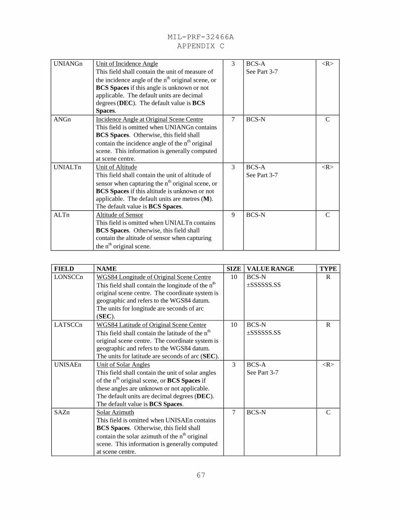
MIL-PRF-32466A
APPENDIX C
67
UNIANGn Unit of Incidence Angle
This field shall contain the unit of measure of
the incidence angle of the nth
original scene, or
BCS Spaces if this angle is unknown or not
applicable. The default units are decimal
degrees (DEC). The default value is BCS
Spaces.
3 BCS-A
See Part 3-7 <R>
ANGn Incidence Angle at Original Scene Centre
This field is omitted when UNIANGn contains
BCS Spaces. Otherwise, this field shall
contain the incidence angle of the nth
original
scene. This information is generally computed
at scene centre.
7 BCS-N C
UNIALTn Unit of Altitude
This field shall contain the unit of altitude of
sensor when capturing the nth
original scene, or
BCS Spaces if this altitude is unknown or not
applicable. The default units are metres (M).
The default value is BCS Spaces.
3 BCS-A
See Part 3-7 <R>
ALTn Altitude of Sensor
This field is omitted when UNIALTn contains
BCS Spaces. Otherwise, this field shall
contain the altitude of sensor when capturing
the nth
original scene.
9 BCS-N C
FIELD NAME SIZE VALUE RANGE TYPE LONSCCn WGS84 Longitude of Original Scene Centre
This field shall contain the longitude of the nth
original scene centre. The coordinate system is
geographic and refers to the WGS84 datum.
The units for longitude are seconds of arc
(SEC).
10 BCS-N
±SSSSSS.SS R
LATSCCn WGS84 Latitude of Original Scene Centre
This field shall contain the latitude of the nth
original scene centre. The coordinate system is
geographic and refers to the WGS84 datum.
The units for latitude are seconds of arc (SEC).
10 BCS-N
±SSSSSS.SS R
UNISAEn Unit of Solar Angles
This field shall contain the unit of solar angles
of the nth
original scene, or BCS Spaces if
these angles are unknown or not applicable.
The default units are decimal degrees (DEC).
The default value is BCS Spaces.
3 BCS-A
See Part 3-7 <R>
SAZn Solar Azimuth
This field is omitted when UNISAEn contains
BCS Spaces. Otherwise, this field shall
contain the solar azimuth of the nth
original
scene. This information is generally computed
at scene centre.
7 BCS-N C
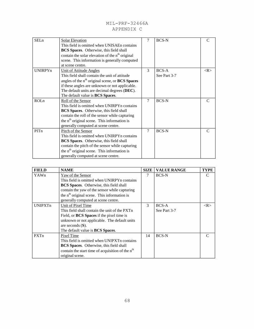
MIL-PRF-32466A
APPENDIX C
68
SELn Solar Elevation
This field is omitted when UNISAEn contains
BCS Spaces. Otherwise, this field shall
contain the solar elevation of the nth
original
scene. This information is generally computed
at scene centre.
7 BCS-N C
UNIRPYn Unit of Attitude Angles
This field shall contain the unit of attitude
angles of the nth
original scene, or BCS Spaces
if these angles are unknown or not applicable.
The default units are decimal degrees (DEC).
The default value is BCS Spaces.
3 BCS-A
See Part 3-7 <R>
ROLn Roll of the Sensor
This field is omitted when UNIRPYn contains
BCS Spaces. Otherwise, this field shall
contain the roll of the sensor while capturing
the nth
original scene. This information is
generally computed at scene centre.
7 BCS-N C
PITn Pitch of the Sensor
This field is omitted when UNIRPYn contains
BCS Spaces. Otherwise, this field shall
contain the pitch of the sensor while capturing
the nth
original scene. This information is
generally computed at scene centre.
7 BCS-N C
FIELD NAME SIZE VALUE RANGE TYPE YAWn Yaw of the Sensor
This field is omitted when UNIRPYn contains
BCS Spaces. Otherwise, this field shall
contain the yaw of the sensor while capturing
the nth
original scene. This information is
generally computed at scene centre.
7 BCS-N C
UNIPXTn Unit of Pixel Time
This field shall contain the unit of the PXTn
Field, or BCS Spaces if the pixel time is
unknown or not applicable. The default units
are seconds (S).
The default value is BCS Spaces.
3 BCS-A
See Part 3-7 <R>
PXTn Pixel Time
This field is omitted when UNIPXTn contains
BCS Spaces. Otherwise, this field shall
contain the start time of acquisition of the nth
original scene.
14 BCS-N C
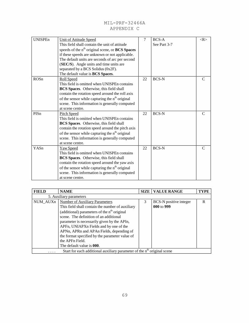
MIL-PRF-32466A
APPENDIX C
69
UNISPEn Unit of Attitude Speed
This field shall contain the unit of attitude
speeds of the nth
original scene, or BCS Spaces
if these speeds are unknown or not applicable.
The default units are seconds of arc per second
(SEC/S). Angle units and time units are
separated by a BCS Solidus (0x2F).
The default value is BCS Spaces.
7 BCS-A
See Part 3-7 <R>
ROSn Roll Speed
This field is omitted when UNISPEn contains
BCS Spaces. Otherwise, this field shall
contain the rotation speed around the roll axis
of the sensor while capturing the nth
original
scene. This information is generally computed
at scene centre.
22 BCS-N C
PISn Pitch Speed
This field is omitted when UNISPEn contains
BCS Spaces. Otherwise, this field shall
contain the rotation speed around the pitch axis
of the sensor while capturing the nth
original
scene. This information is generally computed
at scene centre.
22 BCS-N C
YASn Yaw Speed
This field is omitted when UNISPEn contains
BCS Spaces. Otherwise, this field shall
contain the rotation speed around the yaw axis
of the sensor while capturing the nth
original
scene. This information is generally computed
at scene centre.
22 BCS-N C
FIELD NAME SIZE VALUE RANGE TYPE 5. Auxiliary parameters
NUM_AUXn Number of Auxiliary Parameters
This field shall contain the number of auxiliary
(additional) parameters of the nth
original
scene. The definition of an additional
parameter is necessarily given by the APIn,
APFn, UNIAPXn Fields and by one of the
APNn, APRn and APAn Fields, depending of
the format specified by the parameter value of
the APFn Field.
The default value is 000.
3 BCS-N positive integer
000 to 999 R
. . . . Start for each additional auxiliary parameter of the nth
original scene
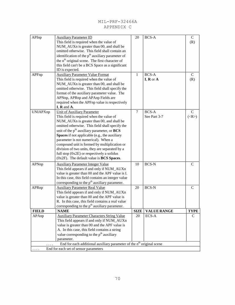
MIL-PRF-32466A
APPENDIX C
70
APInp Auxiliary Parameter ID
This field is required when the value of
NUM_AUXn is greater than 00, and shall be
omitted otherwise. This field shall contain an
identification of the pth
auxiliary parameter of
the nth
original scene. The first character of
this field can't be a BCS Space as a significant
ID is expected.
20 BCS-A C
(R)
APFnp Auxiliary Parameter Value Format
This field is required when the value of
NUM_AUXn is greater than 00, and shall be
omitted otherwise. This field shall specify the
format of the auxiliary parameter value. The
APNnp, APRnp and APAnp Fields are
required when the APFnp value is respectively
I, R and A.
1 BCS-A
I, R or A C
(R)
UNIAPXnp Unit of Auxiliary Parameter
This field is required when the value of
NUM_AUXn is greater than 00, and shall be
omitted otherwise. This field shall specify the
unit of the pth
auxiliary parameter, or BCS
Spaces if not applicable (e.g., the auxiliary
parameter is not numerical). When a
compound unit is formed by multiplication or
division of two units, they are separated by a
full stop (0x2E) or respectively a solidus
(0x2F). The default value is BCS Spaces.
7 BCS-A
See Part 3-7 C
(<R>)
APNnp Auxiliary Parameter Integer Value
This field appears if and only if NUM_AUXn
value is greater than 00 and the APF value is I.
In this case, this field contains an integer value
corresponding to the pth
auxiliary parameter.
10 BCS-N C
APRnp Auxiliary Parameter Real Value
This field appears if and only if NUM_AUXn
value is greater than 00 and the APF value is
R. In this case, this field contains a real value
corresponding to the pth
auxiliary parameter.
20 BCS-N C
FIELD NAME SIZE VALUE RANGE TYPE APAnp Auxiliary Parameter Characters String Value
This field appears if and only if NUM_AUXn
value is greater than 00 and the APF value is
A. In this case, this field contains a string
value corresponding to the pth
auxiliary
parameter.
20 ECS-A C
. . . . End for each additional auxiliary parameter of the nth
original scene . . . . End for each set of sensor parameters
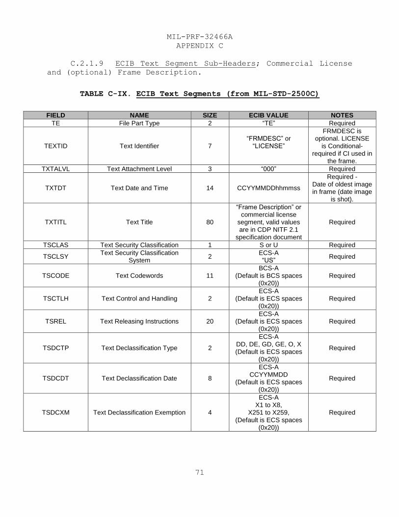
MIL-PRF-32466A
APPENDIX C
71
C.2.1.9 ECIB Text Segment Sub-Headers; Commercial License
and (optional) Frame Description.
TABLE C-IX. ECIB Text Segments (from MIL-STD-2500C)
FIELD NAME SIZE ECIB VALUE NOTES
TE File Part Type 2 “TE” Required
TEXTID Text Identifier 7 “FRMDESC” or
“LICENSE”
FRMDESC is optional. LICENSE
is Conditional- required if CI used in
the frame.
TXTALVL Text Attachment Level 3 “000” Required
TXTDT Text Date and Time 14 CCYYMMDDhhmmss
Required - Date of oldest image in frame (date image
is shot).
TXTITL Text Title 80
“Frame Description” or commercial license
segment, valid values are in CDP NITF 2.1
specification document
Required
TSCLAS Text Security Classification 1 S or U Required
TSCLSY Text Security Classification
System 2
ECS-A “US”
Required
TSCODE Text Codewords 11 BCS-A
(Default is BCS spaces (0x20))
Required
TSCTLH Text Control and Handling 2 ECS-A
(Default is ECS spaces (0x20))
Required
TSREL Text Releasing Instructions 20 ECS-A
(Default is ECS spaces (0x20))
Required
TSDCTP Text Declassification Type 2
ECS-A DD, DE, GD, GE, O, X (Default is ECS spaces
(0x20))
Required
TSDCDT Text Declassification Date 8
ECS-A CCYYMMDD
(Default is ECS spaces (0x20))
Required
TSDCXM Text Declassification Exemption 4
ECS-A X1 to X8,
X251 to X259, (Default is ECS spaces
(0x20))
Required
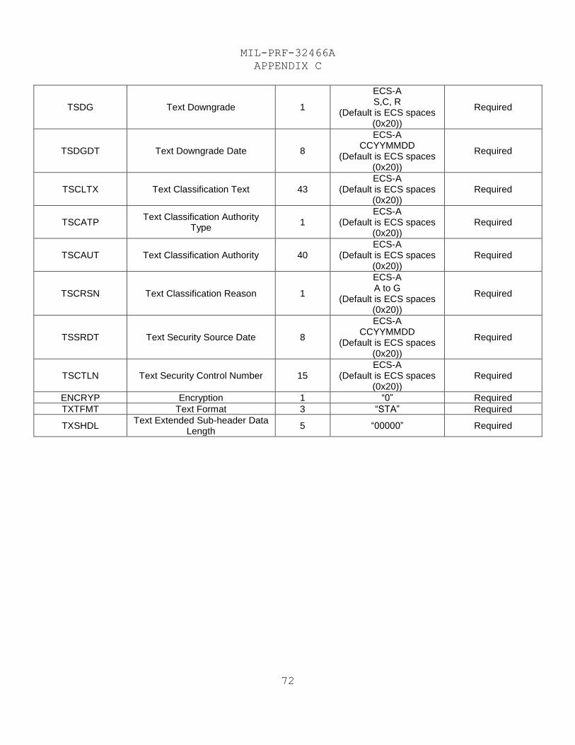
MIL-PRF-32466A
APPENDIX C
72
TSDG Text Downgrade 1
ECS-A S,C, R
(Default is ECS spaces (0x20))
Required
TSDGDT Text Downgrade Date 8
ECS-A CCYYMMDD
(Default is ECS spaces (0x20))
Required
TSCLTX Text Classification Text 43 ECS-A
(Default is ECS spaces (0x20))
Required
TSCATP Text Classification Authority
Type 1
ECS-A (Default is ECS spaces
(0x20)) Required
TSCAUT Text Classification Authority 40 ECS-A
(Default is ECS spaces (0x20))
Required
TSCRSN Text Classification Reason 1
ECS-A A to G
(Default is ECS spaces (0x20))
Required
TSSRDT Text Security Source Date 8
ECS-A CCYYMMDD
(Default is ECS spaces (0x20))
Required
TSCTLN Text Security Control Number 15 ECS-A
(Default is ECS spaces (0x20))
Required
ENCRYP Encryption 1 “0” Required
TXTFMT Text Format 3 “STA” Required
TXSHDL Text Extended Sub-header Data
Length 5 “00000” Required
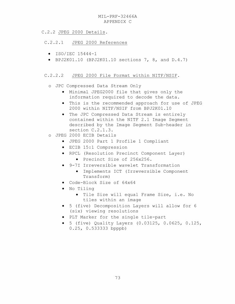
MIL-PRF-32466A
APPENDIX C
73
C.2.2 JPEG 2000 Details.
C.2.2.1 JPEG 2000 References
ISO/IEC 15444-1
BPJ2K01.10 (BPJ2K01.10 sections 7, 8, and D.4.7)
C.2.2.2 JPEG 2000 File Format within NITF/NSIF.
o JPC Compressed Data Stream Only
Minimal JPEG2000 file that gives only the
information required to decode the data.
This is the recommended approach for use of JPEG
2000 within NITF/NSIF from BPJ2K01.10
The JPC Compressed Data Stream is entirely
contained within the NITF 2.1 Image Segment
described by the Image Segment Sub-header in
section C.2.1.3.
o JPEG 2000 ECIB Details
JPEG 2000 Part 1 Profile 1 Compliant
ECIB 15:1 Compression
RPCL (Resolution Precinct Component Layer)
Precinct Size of 256x256.
9-7I Irreversible wavelet Transformation
Implements ICT (Irreversible Component
Transform)
Code-Block Size of 64x64
No Tiling
Tile Size will equal Frame Size, i.e. No
tiles within an image
5 (five) Decomposition Layers will allow for 6
(six) viewing resolutions
PLT Marker for the single tile-part
5 (five) Quality Layers (0.03125, 0.0625, 0.125,
0.25, 0.533333 bpppb)
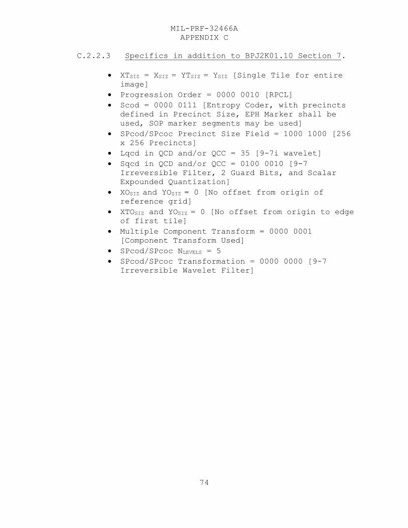
MIL-PRF-32466A
APPENDIX C
74
C.2.2.3 Specifics in addition to BPJ2K01.10 Section 7.
XTSIZ = XSIZ = YTSIZ = YSIZ [Single Tile for entire
image]
Progression Order = 0000 0010 [RPCL]
Scod = 0000 0111 [Entropy Coder, with precincts
defined in Precinct Size, EPH Marker shall be
used, SOP marker segments may be used]
SPcod/SPcoc Precinct Size Field = 1000 1000 [256
x 256 Precincts]
Lqcd in QCD and/or QCC = 35 [9-7i wavelet]
Sqcd in QCD and/or QCC = 0100 0010 [9-7
Irreversible Filter, 2 Guard Bits, and Scalar
Expounded Quantization]
XOSIZ and YOSIZ = 0 [No offset from origin of
reference grid]
XTOSIZ and YOSIZ = 0 [No offset from origin to edge
of first tile]
Multiple Component Transform = 0000 0001
[Component Transform Used]
SPcod/SPcoc NLEVELS = 5
SPcod/SPcoc Transformation = 0000 0000 [9-7
Irreversible Wavelet Filter]
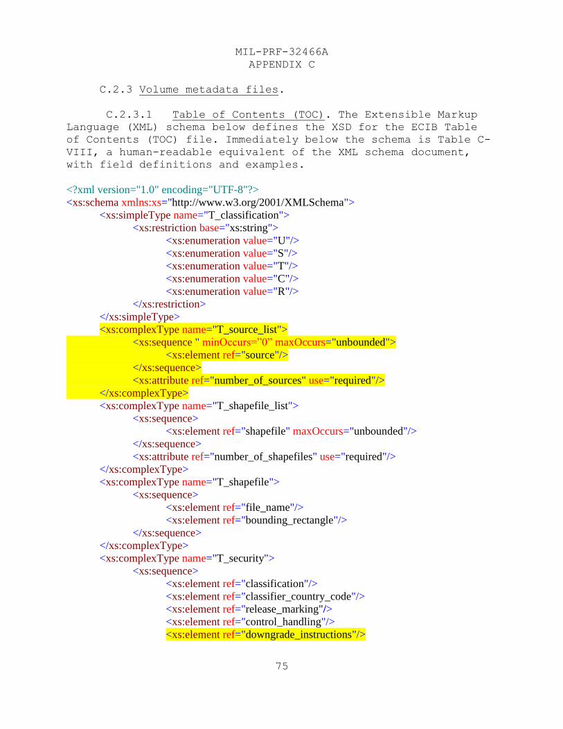
MIL-PRF-32466A
APPENDIX C
75
C.2.3 Volume metadata files.
C.2.3.1 Table of Contents (TOC). The Extensible Markup
Language (XML) schema below defines the XSD for the ECIB Table
of Contents (TOC) file. Immediately below the schema is Table C-
VIII, a human-readable equivalent of the XML schema document,
with field definitions and examples.
<?xml version="1.0" encoding="UTF-8"?>
<xs:schema xmlns:xs="http://www.w3.org/2001/XMLSchema">
<xs:simpleType name="T_classification">
<xs:restriction base="xs:string">
<xs:enumeration value="U"/>
<xs:enumeration value="S"/>
<xs:enumeration value="T"/>
<xs:enumeration value="C"/>
<xs:enumeration value="R"/>
</xs:restriction>
</xs:simpleType>
<xs:complexType name="T_source_list">
<xs:sequence " minOccurs=”0” maxOccurs="unbounded">
<xs:element ref="source"/>
</xs:sequence>
<xs:attribute ref="number_of_sources" use="required"/>
</xs:complexType>
<xs:complexType name="T_shapefile_list">
<xs:sequence>
<xs:element ref="shapefile" maxOccurs="unbounded"/>
</xs:sequence>
<xs:attribute ref="number_of_shapefiles" use="required"/>
</xs:complexType>
<xs:complexType name="T_shapefile">
<xs:sequence>
<xs:element ref="file_name"/>
<xs:element ref="bounding_rectangle"/>
</xs:sequence>
</xs:complexType>
<xs:complexType name="T_security">
<xs:sequence>
<xs:element ref="classification"/>
<xs:element ref="classifier_country_code"/>
<xs:element ref="release_marking"/>
<xs:element ref="control_handling"/>
<xs:element ref="downgrade_instructions"/>
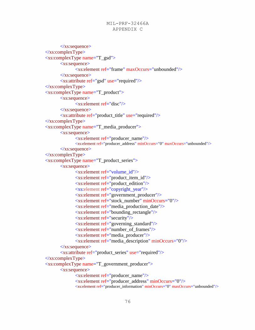
MIL-PRF-32466A
APPENDIX C
76
</xs:sequence>
</xs:complexType>
<xs:complexType name="T_gsd">
<xs:sequence>
<xs:element ref="frame" maxOccurs="unbounded"/>
</xs:sequence>
<xs:attribute ref="gsd" use="required"/>
</xs:complexType>
<xs:complexType name="T_product">
<xs:sequence>
<xs:element ref="disc"/>
</xs:sequence>
<xs:attribute ref="product_title" use="required"/>
</xs:complexType>
<xs:complexType name="T_media_producer">
<xs:sequence>
<xs:element ref="producer_name"/> <xs:element ref="producer_address" minOccurs="0" maxOccurs="unbounded"/>
</xs:sequence>
</xs:complexType>
<xs:complexType name="T_product_series">
<xs:sequence>
<xs:element ref="volume_id"/>
<xs:element ref="product_item_id"/>
<xs:element ref="product_edition"/>
<xs:element ref="copyright_year"/>
<xs:element ref="government_producer"/>
<xs:element ref="stock_number" minOccurs="0"/>
<xs:element ref="media_production_date"/>
<xs:element ref="bounding_rectangle"/>
<xs:element ref="security"/>
<xs:element ref="governing_standard"/>
<xs:element ref="number_of_frames"/>
<xs:element ref="media_producer"/>
<xs:element ref="media_description" minOccurs="0"/>
</xs:sequence>
<xs:attribute ref="product_series" use="required"/>
</xs:complexType>
<xs:complexType name="T_government_producer">
<xs:sequence>
<xs:element ref="producer_name"/>
<xs:element ref="producer_address" minOccurs="0"/> <xs:element ref="producer_information" minOccurs="0" maxOccurs="unbounded"/>
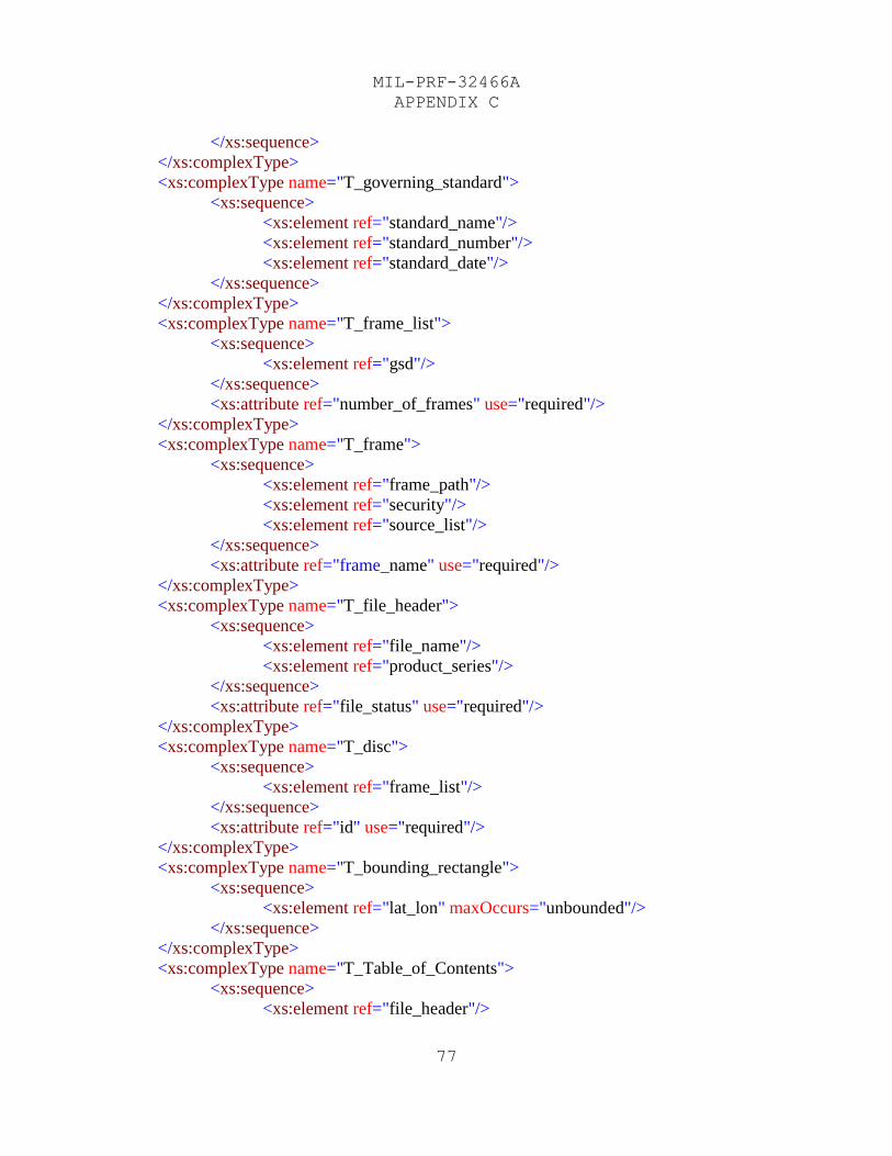
MIL-PRF-32466A
APPENDIX C
77
</xs:sequence>
</xs:complexType>
<xs:complexType name="T_governing_standard">
<xs:sequence>
<xs:element ref="standard_name"/>
<xs:element ref="standard_number"/>
<xs:element ref="standard_date"/>
</xs:sequence>
</xs:complexType>
<xs:complexType name="T_frame_list">
<xs:sequence>
<xs:element ref="gsd"/>
</xs:sequence>
<xs:attribute ref="number_of_frames" use="required"/>
</xs:complexType>
<xs:complexType name="T_frame">
<xs:sequence>
<xs:element ref="frame_path"/>
<xs:element ref="security"/>
<xs:element ref="source_list"/>
</xs:sequence>
<xs:attribute ref="frame_name" use="required"/>
</xs:complexType>
<xs:complexType name="T_file_header">
<xs:sequence>
<xs:element ref="file_name"/>
<xs:element ref="product_series"/>
</xs:sequence>
<xs:attribute ref="file_status" use="required"/>
</xs:complexType>
<xs:complexType name="T_disc">
<xs:sequence>
<xs:element ref="frame_list"/>
</xs:sequence>
<xs:attribute ref="id" use="required"/>
</xs:complexType>
<xs:complexType name="T_bounding_rectangle">
<xs:sequence>
<xs:element ref="lat_lon" maxOccurs="unbounded"/>
</xs:sequence>
</xs:complexType>
<xs:complexType name="T_Table_of_Contents">
<xs:sequence>
<xs:element ref="file_header"/>
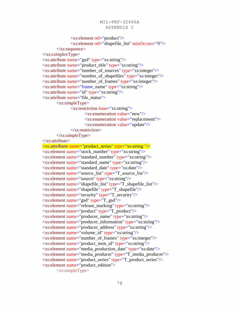
MIL-PRF-32466A
APPENDIX C
78
<xs:element ref="product"/>
<xs:element ref="shapefile_list" minOccurs="0"/>
</xs:sequence>
</xs:complexType>
<xs:attribute name="gsd" type="xs:string"/>
<xs:attribute name="product_title" type="xs:string"/>
<xs:attribute name="number_of_sources" type="xs:integer"/>
<xs:attribute name="number_of_shapefiles" type="xs:integer"/>
<xs:attribute name="number_of_frames" type="xs:integer"/>
<xs:attribute name="frame_name" type="xs:string"/>
<xs:attribute name="id" type="xs:string"/>
<xs:attribute name="file_status">
<xs:simpleType>
<xs:restriction base="xs:string">
<xs:enumeration value="new"/>
<xs:enumeration value="replacement"/>
<xs:enumeration value="update"/>
</xs:restriction>
</xs:simpleType>
</xs:attribute>
<xs:attribute name="product_series" type="xs:string "/>
<xs:element name="stock_number" type="xs:string"/>
<xs:element name="standard_number" type="xs:string"/>
<xs:element name="standard_name" type="xs:string"/>
<xs:element name="standard_date" type="xs:date"/>
<xs:element name="source_list" type="T_source_list"/>
<xs:element name="source" type="xs:string"/>
<xs:element name="shapefile_list" type="T_shapefile_list"/>
<xs:element name="shapefile" type="T_shapefile"/>
<xs:element name="security" type="T_security"/>
<xs:element name="gsd" type="T_gsd"/>
<xs:element name="release_marking" type="xs:string"/>
<xs:element name="product" type="T_product"/>
<xs:element name="producer_name" type="xs:string"/>
<xs:element name="producer_information" type="xs:string"/>
<xs:element name="producer_address" type="xs:string"/>
<xs:element name="volume_id" type="xs:string"/>
<xs:element name="number_of_frames" type="xs:integer"/>
<xs:element name="product_item_id" type="xs:string"/>
<xs:element name="media_production_date" type="xs:date"/>
<xs:element name="media_producer" type="T_media_producer"/>
<xs:element name="product_series" type="T_product_series"/>
<xs:element name="product_edition">
<xs:simpleType>
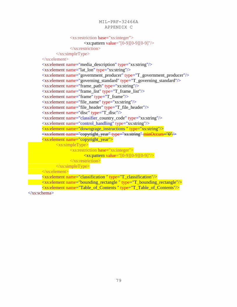
MIL-PRF-32466A
APPENDIX C
79
<xs:restriction base="xs:integer">
<xs:pattern value="[0-9][0-9][0-9]"/>
</xs:restriction>
</xs:simpleType>
</xs:element>
<xs:element name="media_description" type="xs:string"/>
<xs:element name="lat_lon" type="xs:string"/>
<xs:element name="government_producer" type="T_government_producer"/>
<xs:element name="governing_standard" type="T_governing_standard"/>
<xs:element name="frame_path" type="xs:string"/>
<xs:element name="frame_list" type="T_frame_list"/>
<xs:element name="frame" type="T_frame"/>
<xs:element name="file_name" type="xs:string"/>
<xs:element name="file_header" type="T_file_header"/>
<xs:element name="disc" type="T_disc"/>
<xs:element name="classifier_country_code" type="xs:string"/>
<xs:element name="control_handling" type="xs:string"/>
<xs:element name="downgrage_instructions " type="xs:string"/>
<xs:element name="copyright_year" type="xs:string" minOccurs="0"/>
<xs:element name="copyright_year">
<xs:simpleType>
<xs:restriction base="xs:integer">
<xs:pattern value="[0-9][0-9][0-9]"/>
</xs:restriction>
</xs:simpleType>
</xs:element>
<xs:element name="classification " type="T_classification"/>
<xs:element name="bounding_rectangle " type="T_bounding_rectangle"/>
<xs:element name="Table_of_Contents " type="T_Table_of_Contents"/>
</xs:schema>
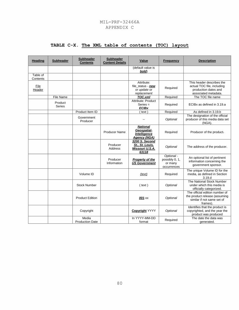
MIL-PRF-32466A
APPENDIX C
80
TABLE C-X. The XML table of contents (TOC) layout
Heading Subheader Subheader Contents
Subheader Content Details
Value Frequency Description
(default value is
bold)
Table of Contents
File Header
Attribute: file_status - new
or update or replacement
Required
This header describes the actual TOC file, including
production dates and associated metadata.
File Name TOC.xml Required The TOC file name
Product Series
Attribute: Product
Series = ECIBx
Required ECIBx as defined in 3.19.a
Product Item ID ( text ) Required As defined in 3.19.b
Government
Producer -- Optional
The designation of the official producer of this media data set
(NGA).
Producer Name
National Geospatial-Intelligence
Agency (NGA)
Required Producer of the product.
Producer Address
3200 S. Second St., St. Louis,
Missouri U.S.A. 63118
Optional The address of the producer.
Producer
Information Property of the US Government
Optional - possibly 0, 1,
or many occurrences
An optional list of pertinent information concerning the
government sponsor.
Volume ID (text) Required The unique Volume ID for the media, as defined in Section
3.19.d
Stock Number ( text ) Optional The National Stock Number under which this media is
officially categorized.
Product Edition 001-xx Optional
The official edition number of the product release (assuming
similar if not same set of frames).
Copyright Copyright YYYY Optional Identifies that the product is
copyrighted, and the year the product was produced
Media
Production Date
In YYYY-MM-DD format
Required The date the data was
generated.
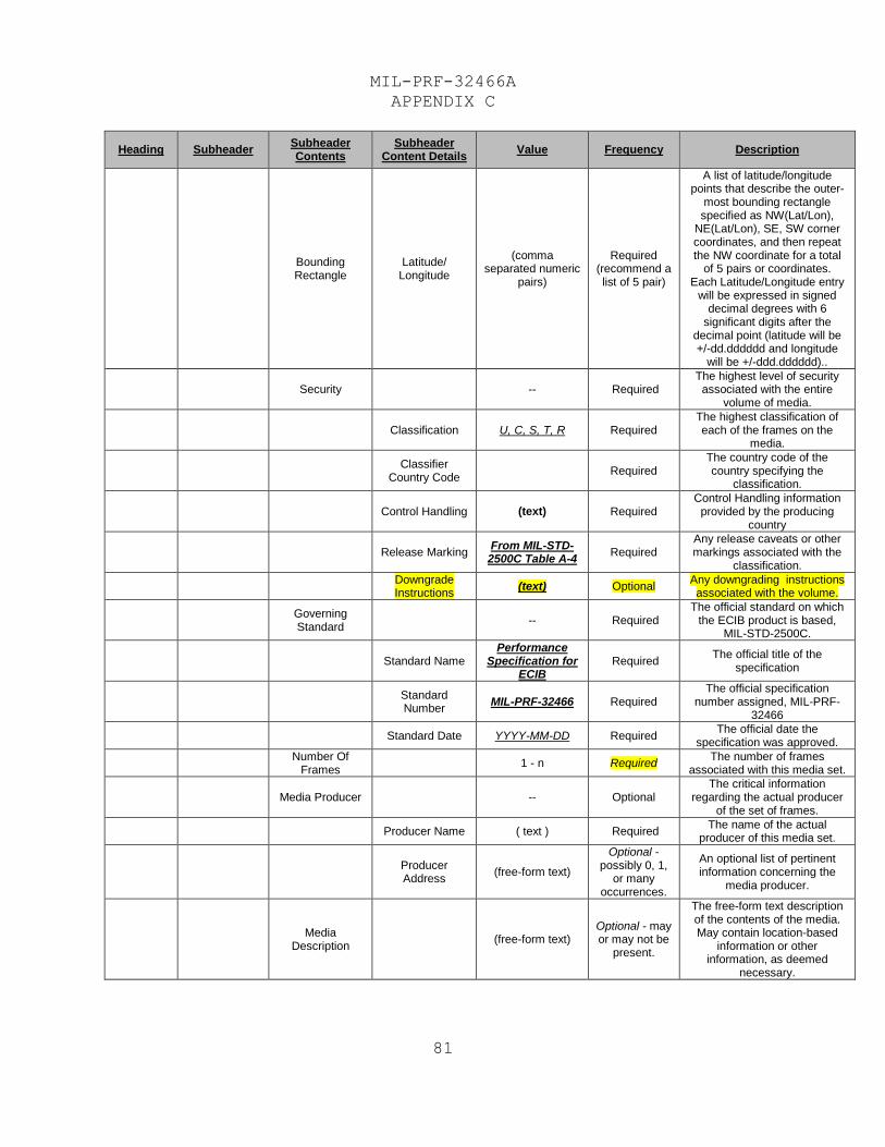
MIL-PRF-32466A
APPENDIX C
81
Heading Subheader Subheader Contents
Subheader Content Details
Value Frequency Description
Bounding Rectangle
Latitude/ Longitude
(comma separated numeric
pairs)
Required (recommend a list of 5 pair)
A list of latitude/longitude points that describe the outer-
most bounding rectangle specified as NW(Lat/Lon),
NE(Lat/Lon), SE, SW corner coordinates, and then repeat the NW coordinate for a total
of 5 pairs or coordinates. Each Latitude/Longitude entry
will be expressed in signed decimal degrees with 6
significant digits after the decimal point (latitude will be +/-dd.dddddd and longitude
will be +/-ddd.dddddd)..
Security -- Required The highest level of security associated with the entire
volume of media.
Classification U, C, S, T, R Required The highest classification of each of the frames on the
media.
Classifier
Country Code Required
The country code of the country specifying the
classification.
Control Handling (text) Required Control Handling information
provided by the producing country
Release Marking From MIL-STD-2500C Table A-4
Required Any release caveats or other markings associated with the
classification.
Downgrade Instructions
(text) Optional Any downgrading instructions associated with the volume.
Governing Standard
-- Required The official standard on which
the ECIB product is based, MIL-STD-2500C.
Standard Name Performance
Specification for ECIB
Required The official title of the
specification
Standard Number
MIL-PRF-32466 Required The official specification
number assigned, MIL-PRF-32466
Standard Date YYYY-MM-DD Required The official date the
specification was approved.
Number Of
Frames 1 - n Required
The number of frames associated with this media set.
Media Producer -- Optional The critical information
regarding the actual producer of the set of frames.
Producer Name ( text ) Required The name of the actual
producer of this media set.
Producer Address
(free-form text)
Optional - possibly 0, 1,
or many occurrences.
An optional list of pertinent information concerning the
media producer.
Media
Description (free-form text)
Optional - may or may not be
present.
The free-form text description of the contents of the media. May contain location-based
information or other information, as deemed
necessary.
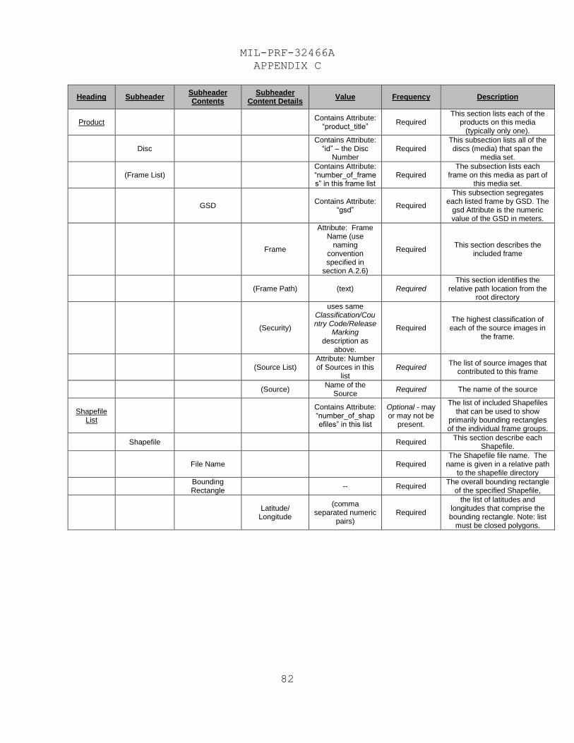
MIL-PRF-32466A
APPENDIX C
82
Heading Subheader Subheader Contents
Subheader Content Details
Value Frequency Description
Product Contains Attribute:
“product_title” Required
This section lists each of the products on this media
(typically only one).
Disc Contains Attribute:
“id” – the Disc Number
Required This subsection lists all of the discs (media) that span the
media set.
(Frame List) Contains Attribute: “number_of_frames” in this frame list
Required The subsection lists each
frame on this media as part of this media set.
GSD Contains Attribute:
“gsd” Required
This subsection segregates each listed frame by GSD. The
gsd Attribute is the numeric value of the GSD in meters.
Frame
Attribute: Frame Name (use
naming convention specified in
section A.2.6)
Required This section describes the
included frame
(Frame Path) (text) Required This section identifies the
relative path location from the root directory
(Security)
uses same Classification/Country Code/Release
Marking description as
above.
Required The highest classification of each of the source images in
the frame.
(Source List) Attribute: Number of Sources in this
list Required
The list of source images that contributed to this frame
(Source) Name of the
Source Required The name of the source
Shapefile List
Contains Attribute: “number_of_shapefiles” in this list
Optional - may or may not be
present.
The list of included Shapefiles that can be used to show
primarily bounding rectangles of the individual frame groups.
Shapefile Required This section describe each
Shapefile.
File Name Required The Shapefile file name. The
name is given in a relative path to the shapefile directory
Bounding Rectangle
-- Required The overall bounding rectangle
of the specified Shapefile,
Latitude/
Longitude
(comma separated numeric
pairs) Required
the list of latitudes and longitudes that comprise the bounding rectangle. Note: list
must be closed polygons.
MIL-PRF-32466A
INDEX
83
C.2.3.2 Shapefiles.
o Frame Extent Shapefile (for all frames on a media)
Each frame included shall be represented by a
polygon representing the geographic extent of the
frame.
Frame shapefiles shall be named with respect to
the EPF directory in the following manner:
./SHAPEFILE/<frame file directory
name>_frames.shp. The <frame file directory name>
corresponds to the frame file directory name
defined in Section 3.7.5.e. If the product
contains one 1 degree cell, or one quarter cell,
there will be one suite of shapefiles named in
accordance with Section 3.7.5.e. If the product
contains more than one 1 degree cell then there
will be a separate suite of shapefiles for every
1 degree cell, each named in accordance with the
frame file directory name defined in Section
3.7.5.e. A suite of shape files includes the
following files: *.shp, *.dbf, *.prj, *.shx.
Each frame polygon is required to have the
following Column Names and associated attributes:
FID (supplied by ESRI)
Shape
Frame_Name
Prod_Date (YYYYMMDD date frame is produced)
o Source Image Extent Shapefile (for all frames on a
media)
Each source used to create the frames on the
media shall be represented by a polygon
representing the geographic extent of the source
image.
MIL-PRF-32466A
INDEX
84
Source Image shapefiles shall be named with
respect to the EPF directory in the following
manner:./SHAPEFILE/<frame file directory
name><C>_source.shp The <frame file directory
name> corresponds to the frame file directory
name defined in Section 3.7.5.e. If the product
contains one 1 degree cell, or one quarter cell,
there will be one suite of shapefiles named in
accordance with Section 3.7.5.e. If the product
contains more than one 1 degree cell then there
will be a separate suite of shapefiles for every
1 degree cell, each named in accordance with the
frame file directory name defined in Section
3.7.5.e. A suite of shape files includes the
following files: *.shp, *.dbf, *.prj, *.shx. The
<C> represents the classification of the source
image shapefile, where “U” indicates an
Unclassified source shapefile, and “S” indicates
a Secret source shapefile.
Note: When the ECIB is an expurgated “Z” the “U”
or “S” should be used to identify the shapefile
classification.
Note: Consult the ECIB Product Specific Guidance
for specific instructions relating to “source”
[image] shapefile metadata accuracy reporting
when the product data is derived from All
Sources.
Each source image polygon will have the following
Column Names with associated attributes:
FID (supplied by ESRI)
Classif (classification of this shapefile,
either “U” or “S”)
Release (Releasability or blank)
Shape
Sensor_Typ (source sensor name, free text,
e.g. “WV02”)
MIL-PRF-32466A
INDEX
85
Img_Date (YYYYMMDD date of source image)
GSD – in meters (4 characters)
Abs_HorAcc (meters, 5 characters. Post
process value)
Rel_HorAcc (meters, 5 characters. Post
process value)
There is a 10 character limitation on the DBF
file column header names. Reference:
http://support.esri.com/usa/knowledgebase/techart
icles/detail/31008
o The projection of the Shapefile for a given zone will
be the same as the projection of the frames within
that zone.
MIL-PRF-32466A
INDEX
86
Acronyms, 23
Applicable Documents, 2
ARC system projection, 25
Color Reduction, 19
Compression Algorithm, 19
Coordinate Reference Systems, 15
Coordinate Transformations, 25
Coordinates, Non-polar, 15
Coordinates, Polar, 15
Coordinates, WGS-84, 15
Data File Organization, 9
Decompression, 20
Distortion, Non-polar, 15
Distortion, Polar, 16
Distribution Frames, 8
First Article, 5
Frame and virtual subframe
structure, 43
Frame and Virtual Subframe Tabular
Data, 43
Frame Description, 12, 20
Frame File Size Computation, 47
Frame Naming Convention, 37
Frame Structure, 11
Frame Structure for Polar Regions,
13
Frame Updates, 20
Government Documents, 2
Horizontal Accuracy, 5
Horizontal Datum, 6
Image Formats, 16
Image Segment Sub-Header, 54
Imagery Seams, 8
Intended use, 23
International Standardization
Agreements, 26
JPEG 2000 Details, 72
Media and Recording Formats, 7
Media Labeling, 20
NGA Help Desk, 26
NITF 2.1 File Structure, 48
Non-Government Publications, 4
Non-polar Frame Overlap, 13
Non-polar frame pixel coordinates
of a geographic point, 29
Non-polar latitude and longitude of
an ECIB frame pixel, 29
Nonpolar Zone Computation, 38
Nonstandard Distribution, 22
Notes, 23
Numbering & Origin Conventions, 12
Order of Precedence, 5
Orthorectification, 19
Packaging, 23
Pixel Spacing, 11
Polar frame pixel coordinates of a
geographic point, 33
Polar latitude and longitude of an
ECIB frame pixel, 32
Polar zone additional computations,
42
Polar Zone Overlap, 13
Product Description, 6
Project Distortion, 15
Projection System, 8
Purpose, 2
Requirements, 5
Resolution, 2, 6
Scope, 2, 27, 50, 51
Shapefiles, 78
Source Imagery, 7
Source Support Data, 19
Standard Distribution, 22
Storage Requirements, 20
Subject term (key word) listing, 23
Table of Contents (TOC), 74
Vertical Accuracy, 6
Volume metadata files, 74
Volume Support Data, 19

MIL-PRF-32466A
CONCLUDING MATERIAL
87
Custodians: Preparing Activity:
Army - MI NGA - MP
Navy - NO (Project GINT-2016-004)
Air Force - 09
Review Activities:
Army - AV
Navy - AS, CG, MC
Air Force - 11, 33, 99
DIA - DI
DISA - DC1
NSA - NS
OSD – DMS
NOTE: The activities listed above were interested in this
document as of the date of this document. Since
organizations and responsibilities can change, you should
verify the currency of the information above by using the
ASSIST Online database at https://assist.dla.mil/.