Methods, systems and devices for improving ventilation in a lung area
23
(19) United States Wondka US 20050005936A1 (12) Patent Application Publication (10) Pub. N0.: US 2005/0005936 A1 (43) Pub. Date: Jan. 13, 2005 (54) (76) (21) (22) (60) (51) (52) METHODS, SYSTEMS AND DEVICES FOR IMPROVING VENTILATION IN A LUNG AREA Inventor: Village, CA (US) Correspondence Address: ANTHONY DAVID WONDKA 944 EVENSTAR AVENUE WESTLAKE VILLAGE, CA 91361 (US) Appl. No.: Filed: 10/870,849 Jun. 17, 2004 Anthony David Wondka, Westlake Related US. Application Data Provisional application No. 60/479,213, ?led on Jun. 18, 2003. Publication Classi?cation Int. Cl.7 .................................................. .. A61M 16/00 US. Cl. ........ .. 128/204.18; 128/204.21; 128/204.23 / q \7' 000 \ an a o o o 0 o o 1:: :1 D :1 :1 (57) ABSTRACT Methods, systems and devices are described for neW modes of ventilation in Which speci?c lung areas are ventilated With an indwelling trans-tracheobronchial catheter for the pur pose of improving ventilation and reducing hyperin?ation in that speci?c lung area, and for redistributing inspired air to other healthier lung areas, for treating respiratory disorders such as COPD, ARDS, SARS, CF, and TB. Trans-Tracheo bronchial Segmental Ventilation (TTSV) is performed on either a naturally breathing or a mechanical ventilated patient by placing a uniquely con?gured indwelling catheter into a bronchus of a poorly ventilated speci?c lung area and providing direct ventilation to that area. The catheter can be left in place for extended periods Without clinician atten dance or vigilance. Ventilation includes delivery of respira tory gases, therapuetic gases or agents and evacuation of stagnant gases, mixed gases or Waste ?uids. Typically the catheter’s distal tip is anchored Without occluding the bron chus but optionally may intermittently or continuously occlude the bronchus. TTSV is optionally performed by insuf?ation only of the area, or by application of vacuum to the area, can include elevating or reducing the pressure in the targeted area to facilitate stagnant gas removal, or can include blocking the area to divert inspired gas to better functioning areas. /7'0 / / /Z5 /2/ 32
Transcript of Methods, systems and devices for improving ventilation in a lung area
(19) United States
Wondka
US 20050005936A1
(12) Patent Application Publication (10) Pub. N0.: US 2005/0005936 A1 (43) Pub. Date: Jan. 13, 2005
(54)
(76)
(21)
(22)
(60)
(51) (52)
METHODS, SYSTEMS AND DEVICES FOR IMPROVING VENTILATION IN A LUNG AREA
Inventor: Village, CA (US)
Correspondence Address: ANTHONY DAVID WONDKA 944 EVENSTAR AVENUE WESTLAKE VILLAGE, CA 91361 (US)
Appl. No.:
Filed:
10/870,849
Jun. 17, 2004
Anthony David Wondka, Westlake
Related US. Application Data
Provisional application No. 60/479,213, ?led on Jun. 18, 2003.
Publication Classi?cation
Int. Cl.7 .................................................. .. A61M 16/00
US. Cl. ........ .. 128/204.18; 128/204.21; 128/204.23
/ q \7' 000
\ an a o o o 0 o o 1:: :1 D
:1 :1
(57) ABSTRACT Methods, systems and devices are described for neW modes of ventilation in Which speci?c lung areas are ventilated With an indwelling trans-tracheobronchial catheter for the pur pose of improving ventilation and reducing hyperin?ation in that speci?c lung area, and for redistributing inspired air to other healthier lung areas, for treating respiratory disorders such as COPD, ARDS, SARS, CF, and TB. Trans-Tracheo bronchial Segmental Ventilation (TTSV) is performed on either a naturally breathing or a mechanical ventilated patient by placing a uniquely con?gured indwelling catheter into a bronchus of a poorly ventilated speci?c lung area and providing direct ventilation to that area. The catheter can be left in place for extended periods Without clinician atten dance or vigilance. Ventilation includes delivery of respira tory gases, therapuetic gases or agents and evacuation of stagnant gases, mixed gases or Waste ?uids. Typically the catheter’s distal tip is anchored Without occluding the bron chus but optionally may intermittently or continuously occlude the bronchus. TTSV is optionally performed by insuf?ation only of the area, or by application of vacuum to the area, can include elevating or reducing the pressure in the targeted area to facilitate stagnant gas removal, or can include blocking the area to divert inspired gas to better functioning areas.
/7'0 /
/ /Z5 /2/
32

Patent Application Publication Jan. 13, 2005 Sheet 1 0f 12 US 2005/0005936 A1
F/auk'e 1b 1 '
ET /
FIGURE 1d
Patent Application Publication Jan. 13, 2005 Sheet 2 0f 12 US 2005/0005936 A1
._) O 32.
pap/p5 Z5
Patent Application Publication Jan. 13, 2005 Sheet 3 0f 12 US 2005/0005936 A1
Patent Application Publication Jan. 13, 2005 Sheet 4 0f 12 US 2005/0005936 Al

Patent Application Publication Jan. 13, 2005 Sheet 6 0f 12 US 2005/0005936 A1
Eda/(6 ,6
— EEFM€ ~
LUNG TIDAL VOLUMZ
q. 2 F. 4 i v cTL 2
e l .m 5 In
2 Al DNWEBE
5 2
L0 WFR LOEES VULUM E 25'5
wqxmmmau _ _
6 _
m H W,
E \) d. F q\ h“ W»
Z w 0 5 E m
5 LT K 2 m
K w v
/ w W m. @?vwqxmmg .m§3s>


Patent Application Publication Jan. 13, 2005 Sheet 8 0f 12 US 2005/0005936 A1

Patent Application Publication Jan. 13, 2005 Sheet 9 0f 12 US 2005/0005936 A1

Patent Application Publication Jan. 13, 2005 Sheet 10 0f 12 US 2005/0005936 A1
F/G [MP/0
F/6. m5

Patent Application Publication Jan. 13, 2005 Sheet 11 0f 12 US 2005/0005936 A1
F16 W85”

Patent Application Publication Jan. 13, 2005 Sheet 12 0f 12 US 2005/0005936 A1
626
6/3 6/5 5/3?
w; (70% 606 6x60? 608, 60a

US 2005/0005936 A1
METHODS, SYSTEMS AND DEVICES FOR IMPROVING VENTILATION IN A LUNG AREA
CROSS REFERENCE TO RELATED APPLICATIONS
[0001] This application claims Provisional Patent Appli cation No. 60/479,213 as a predicate application With the respective priority ?ling date of Jun. 18, 2003.
STATEMENT REGARDING FEDERALLY SPONSORED RESEARCH OR DEVELOPMENT
[0002] Not Applicable
DESCRIPTION OF ATTACHED APPENDIX
[0003] Not Applicable
GOVERNMENT INVENTION OR CONTRACT WITH GOVERNMENT
[0004] None
ENTITY
[0005] Small Entity Concern
PRIOR ART
[0006] US. Pat. Nos. 4,825,859; 4,838,255; 4,850,350; 4,967,743; 5,000,175; 5,134,996; 5,186,167; 5,193,533; 5,255,675; 5,460,613; 5,513,628; 5,598,840; 5,791,337; 5,904,648; 6,227,200; 6,520,183; 6,575,944; 6,575,944; US. Published Patent Applications: 20010035185; 20020179090.
OTHER RELATED APPLICATIONS
[0007] Fink J. B.; Helium-oxygen: An Old Therapy Creates New Interest. (J Resp Care Pract April 1999; 71-76)
[0008] Christopher K L et al.; T ranstracheal oxygen for refractory hypoxemia. (JAMA 1986; 256: 494-7)
[0009] Gaebek J. B. et al; E?icacy ofSelective Intra bronchial Air Insu?lation in Acute Lobar Collapse. (Am J of Sur 1992; 164:501-505)
[0010] AARC Clinical Practice Guideline: Oxygen Therapy in the Home or Extended Care Facility (Respir Care 1992; 37:918-922)
[0011] MacIntyre, Neil; Long-term Oxygen Therapy: Conference Summary (Respir Care 2000; 45(2):237 245) VHA/DOD Clinical Proactice Guideline for the Management of Chronic Obstructive Pulmonary Disease (VHA 1999 August 116)
[0012] Blanch, L; Clinical Studies of Tracheal Gas Insu?lation (Respir Care 2001 ;46(2): 158-166)
BACKGROUND OF THE INVENTION
[0013] The present invention relates to the ?eld of respi ratory therapy and speci?cally to the ?eld of lung ventilation to treat a variety of pulmonary diseases.
[0014] Lung diseases are the number one category of diseases and a leading cause of death WorldWide. Some lung diseases, such as Chronic Obstructive Pulmonary Disease
Jan. 13, 2005
(COPD), Acute Respiratory Distress Syndrome (ARDS), Severe Acute Respiratory Syndrome (SARS) and cystic ?brosis (CF) usually require some form of ventilation assis tance or delivery of therapeutic agents in order to clinically improve the patient.
[0015] COPD in particular effects tens of millions of people and is one of the top ?ve leading causes of death. COPD is a spectrum of problems, including bronchitis and emphysema, and involves airWay obstruction, lung elasticity loss and trapping of stagnant COZ-rich air in the lung. Emphysema, the Worst form of COPD, occurs When there is a breakdoWn in the elasticity in the lung changing clusters of individual alveoli into large air pockets, thereby signi? cantly reducing the surface area for gas transfer. In some cases air leaks out of the compromised Walls of the minute airWays to the periphery of the lung causing the membra nous lining to separate and forming large air vesicles called bullae. Also due to elasticity loss, small conducting airWays leading to the alveoli become ?accid and have a tendency to collapse during exhalation, trapping large volumes of air in the noW enlarged air pockets, thus reducing bulk air ?oW exchange and causing CO2 retention in the trapped air. Mechanically, because of the large amount of trapped air at the end of exhalation, knoWn as elevated residual volume, the intercostal and diaphragmatic inspiratory muscles are forced into a pre-loaded condition, reducing their leverage at the onset of an inspiratory effort thus increasing Work-of breathing and dyspnea. Also, areas With more advanced emphysema and more trapped air tend to comprise the majority of the chest cavity volume and tend to ?ll prefer entially during inspiration due to their loW elasticity, thus causing the healthier portions to be disproportionately com pressed rather than in?ating normally during inspiration and receiving their share of inspired air. In emphysema therefore more effort is expended to inspire less air and the air that is inspired contributes less to gas exchange.
[0016] ARDS is a respiratory insufficiency caused by a variety of underlying problems such as lung injury, infec tion, edema, or atelectasis. SARS is a sudden respiratory insufficiency and appears to be caused by a viral infection. CF is a genetic condition in Which airWays secrete copious amounts of mucus and are in?amed.
[0017] Conventionally prescribed therapies for COPD and ARDS and sometimes SARS and CF include pharmacologi cal agents (beta-agonists, aerosoliZed bronchodilators, anti in?ammatories and mucolytics), supplemental long term oxygen therapy (LTOT) delivered nasally or via trache otomy, BiLevel Continuous Positive AirWay Pressure (BiPAP), Which loWers Work of inspiration by providing a steady stream of pressure, Tracheal Oxygen Gas Insuf?ation (TGI), described by Christopher, JAIVIA 1986; 256: 494-7, Which reduces CO2 content in the upper airWays thus alloW ing higher O2 concentrations to reach the distal airWays, respiratory muscle rehabilitation, pulmonary hygiene, such as lavage and percussion therapy, lung volume reduction surgery (LVRS) and lung transplantation These thera pies all have certain disadvantages and limitations With regard to effectiveness, targeting accuracy, risk or availabil ity. Usually, after progressive decline in lung function despite attempts at therapy, patients become physically incapacitated or sometimes require more invasive mechani cal ventilation to survive in Which case Weaning from ventilator dependency is often times difficult. Conventional

US 2005/0005936 A1
invasive ventilation modes include Continuous Mechanical Ventilation (CMV), Synchronized Intermittent Mechanical Ventilation (SIMV), Positive End Expiratory Pressure (PEEP) therapy, and high frequency jet ventilation (HFJV).
[0018] Some neWer ventilatory methods have been studied in the attempt to improve treatment of COPD and ARDS. One such method described by Fink, J Resp Care Pract April 1999; 71 is ventilation of a lung With gases of loW molecular Weights and loW viscosity, such as helium-oxygen mixtures or nitric oxide, in order to decrease gas ?oW resistance and loWer surface tension in distal airWays and alveolar surfaces, thus increasing oxygen transfer across the alveolar surface into the blood. Another neW method includes liquid per?uorocarbon ventilation Which can dis place mucus in distal airWays While still conducting oxygen thus improving gas ?oW. Another method never successfully commercialiZed is Negative End Expiratory Pressure (NEEP), Which helps remove CO2-rich gas during the exhalation cycle. These invasive methods typically ventilate COPD and ARDS patients more effectively then conven tional invasive ventilation modes and may improve Wean ing, but they are signi?cantly limited in ef?cacy because they can not easily be provided as chronic treatments and are not target speci?c. Rather they are inherently designed to treat the Whole lung from the upper airWay and hence do not address the signi?cant problem of hyperin?ation and areas of trapped stagnant gas, nor the problem of maldistribution of inspiratory gas volume.
[0019] Some additional devices and techniques have been invented With the aim of improving ef?cacy. US. Pat. No. 6,575,944 describes a catheter that is used for medication delivery through an endotracheal tube. That invention is good for pharmacological therapy on a mechanically venti lated patient, hoWever the invention does not address the signi?cant ventilation needs of the diseased lungs such as trapped gas and hyperin?ated lungs.
[0020] Us. Pat. No. 6,520,183 describes a catheter used to block on lung and delivery anesthesia to the other lung. That invention and other like it can only be used for one lung ventilation, almost alWays for surgery. That invention can be used in the unintended use of shunting ventilation to one lung, if the other lung is too diseased, hoWever this usage Would have signi?cant limitations in that lobar or segmental sections of lung could not be individually blocked; hence this therapy Would not be selective at all.
[0021] US. Pat. Nos. 6,227,200; 5,791,337; 5,598,840; 5,513,628; 5,460,613; 5,134,996; and 4,850,350 all describe catheters used for intermittently accessing and suctioning the trachea and main stem bronchi during through a tracheal tube during mechanical ventilation. That invention does not address the severe ventilation problems of the diseased lung, such as trapped air, hyperin?ation, and poor air?oW and perfusion distribution.
[0022] Us. Pat. No. 5,904,648 describes a catheter for blocking air?oW to one lung in order to ventilate and deliver anesthesia to the other side While the blocked side is being operated on. Again, that invention does not address improv ing ventilation and gas exchange.
[0023] Us. Pat. Nos. 5,255,675 and 5,186,167 describe a catheter placed in the trachea through Which the trachea is insuf?ated With oxygen. In clinical practice that invention
Jan. 13, 2005
and others like it have been proven to reduce the amount of CO2 in the lung and thus improve ventilation, hoWever because the therapy described in this invention can inher ently only be applied to the upper airWays, it does nothing to improve the signi?cant hyperin?ation, air trapping and air?oW and perfusion maldistribution of diseased lungs, and thus the therapy is severely limited. Indeed this therapy has not been Well received clinically because the amount of bene?t does not justify the added attention required.
[0024] US. Pat. No. 5,193,533 describes an invention similar to Us. Pat. No. 5,255,675 in Which high frequency ventilation is administered to the trachea to improve oxy genation. That invention has been proven clinically useful during short term medical procedures because the lung can be effectively mechanically ventilated at loWer pressures but it is not useful as a subacute or chronic therapy as it does not reduce the air trapping, hyperin?ation, or air?oW and blood perfusion maldistribution.
[0025] US. Pat. Nos. 4,967,743; 4,838,255 and 4,825,859 describe a catheter for suctioning and ravaging the airWays. That invention is limited to managing the airWay integrity and pulmonary hygiene and is not suited for directly improv ing the underlying causes of air trapping, hyperventilation, and air ?oW maldistribution in the lung.
[0026] US. Patent Application 20020179090 describes an aspiration catheter for removing phlegm from a lung. This invention is only useful in airWay management and is not suited for directly improving the underlying causes of air trapping, hyperventilation, and air ?oW maldistribution in the lung.
[0027] US. Patent Application 20010035185 describes a nasal-pharyngeal catheter for delivering breathing gases to the pharynx to supplement regular ventilation or breathing. That invention is incrementally more effective than LTOT in that the gases are delivered more effectively but unfortu nately the technique can not directly improve the underlying causes of air trapping, hyperventilation, and air ?oW mald istribution in the lung
[0028] It must be emphasiZed that an effective ventilation treatment should ideally target speci?c areas of the lung that are most diseased yet all the methods described in the prior art employ ventilation on the entire lung as a Whole, rather than on targeted lung areas that are more diseased. There fore, all knoWn ventilation modes alloW trapped CO2 to persist in the Worst effected areas of the lung and alloW these areas to remain hyperin?ated With the CO2-rich air, thus taking up valuable space in the chest cavity and compressing other potentially contributory lung areas. Other inventions or conventional therapies are either to traumatic, too tran sient, not site-speci?c, too experimental or not effective. The present invention disclosed herein addresses these short comings as Will become apparent in the later descriptions.
BRIEF SUMMARY OF THE INVENTION
[0029] The present invention disclosed herein takes into consideration the problems and challenges not solved by the aforementioned prior art methods. In summary, this inven tion accomplishes (1) effective and direct cannulation of the lung area requiring treatment for a targeted site-speci?c treatment, (2) provides the option of sub-chronic or chronic treatment Without the vigilance of a clinician, either in the

US 2005/0005936 A1
hospital setting or in the home-care setting, and can be titrated accordingly, (3) is atraumatic, (4) improves hyper in?ation and stagnant gas trapping in the distal spaces, (5) improves the maldistribution of air?oW and blood perfusion, and (5) is cost effective.
[0030] The present invention provides a method for directly ventilating an area in a lung to improve the gas exchange in that area, typically for the treatment of COPD, although other respiratory diseases, such as ARDS, SARS, CF and TB may also bene?t from this approach. The method, Trans-Tracheobronchial Segmental Ventilation (TTSV), is performed by (a) catheteriZing the lung area With an indWelling catheter that can be left in place for extended periods Without the vigilance of a clinician, and (b) venti lating the lung area via the catheter by delivering a venti lation gas and/or therapeutic substance such as a gas, liquid, solid or plasma, during an insuf?ation phase and removing Waste and mixed gases from the area during an exhaust phase. The scienti?c principles employed to accomplish TTSV are ?uid dynamics, the physical laWs of mass transfer, i.e., gas and tissue diffusivity, gas concentration gradients and pressure gradients, as Well as the physical laWs of collapsible tubes and hemoglobin biochemistry laWs.
[0031] In a preferred embodiment of the present invention the feeding bronchus of the targeted lung area is catheteriZed With an indWelling catheter anchored in the bronchus such that it can remain in place for extended periods Without being attended by a person. The catheter enters the bronchial tree from the upper airWay, either through an arti?cial airWay such as a tracheal tube or through a natural airWay such as the nasal passage or through a percutaneous incision such as a cricothyrotomy and is advanced to the targeted LUNG AREA through the bronchial tree With endoscopic or ?uoroscopic guidance, Where the tip is anchored in the airWay. For ventilation and hygiene considerations, the catheter entry point into the body typically includes a self-sealing and tensioning connector that controls ?uid from escaping from around the catheter shaft, but Which permits the catheter to slide axially to compensate for patient movement or for elective catheter repositioning. The ten sioning connector also serves to prevent inadvertent dislodg ing of the catheter’s distal end anchor from the bronchus. In accordance With this embodiment the catheter includes at least one lumen through Which the ventilation or therapeutic gas is delivered or insuf?ated directly into the targeted lung area and through Which CO2-rich mixed gas is removed or exhausted from the targeted area. Gas removal from the area is typically enhanced by applying vacuum, as opposed to passive exhaust, hoWever a loW vacuum level is applied to avoid the collapse of airWays and trapping gas behind the then collapsed airWays. Optionally the segmental ventilation gas delivery/removal cycle is synchroniZed With the breath ing pattern of the complete lung either during natural breathing or during mechanical ventilation but can also be asynchronous. The primary segmental ventilation param eters, ?oW, pressure and frequency, are regulated so as to create the desired volume delivery to the targeted area, or alternatively the desired pressure delivery to and in the targeted area, or still alternatively the desired gas composi tion in the targeted area or perfusion netWork thereof. The segmental ventilation parameters are measured to facilitate such regulation and to maintain safe conditions such as to prevent barotrauma.
Jan. 13, 2005
[0032] Still in accordance With the preferred embodiment of the present invention, the ?uid delivered to the targeted area may include standard breathing gases such as ?ltered air-oxygen mixtures, or may include therapeutic gases, such as helium, helium-oxygen mixtures, nitric oxide, other loW molecular Weight gases and gases enriched With particaliZed medicants, or may include liquids such as per?uorocarbons. Hereafter, the various ?uids potentially used in TTSV Will be referred to as simply ‘ventilation gas’.
[0033] Still in accordance With the preferred embodiment of the present invention, the proximal end of the catheter is kept external to the patient and is connected to a segmental ventilation gas control unit. The gas control unit comprises a supply of ventilation gas, or alternately an input connec tion means to a supply thereof, and comprises the requisite valves, pumps, regulators, conduits, sensors and control electronics to control the desired pressure and/or ?oW deliv ery of the gas and to control the desired pressure in the lung area. The gas control unit may comprise a replaceable or re?llable modular cartridge of compressed or concentrated ventilation gas and/or may comprise a pump system that receives ventilation gas from a reservoir and ejects the ventilation gas into the catheter at the desired parameters. The gas control unit further comprises fail-safe over-pres sure relief mechanisms to protect against inadvertent lung barotrauma. The gas control unit also typically comprises a negative pressure generating source and control system also connectable to a lumen in the catheter for the previously described gas removal phase, i.e., exhaust phase, of the gas control unit ventilation cycle. The gas control unit may be con?gured to be remove-ably or permanently attached inter nally or externally to a standard lung ventilator, in the case of performing gas control unit on a mechanically ventilated patient, or may be an independent unit optionally to be Worn by an ambulatory patient, in the case of performing TTSV on for example a home-based naturally breathing patient. It is appreciated that the gas control unit Will have the requisite control and monitoring interface to alloW the user to control and monitor the relevant parameters of the TTSV, as Well as the requisite poWer source, enclosure, electronics, etc.
[0034] In an optional embodiment of the present inven tion, an average pressure is created in the targeted lung area Which is slightly elevated compared to the average pressure in the remainder of the lung. This is achieved by measuring and regulating the lung area and TTSV parameters accord ingly. The purpose of the elevated pressure is four fold: (1) it Will facilitate a dilitation of the distal airWays to facilitate communication of the ventilation gas With the otherWise poorly communicating lung lobules and alveoli; (2) it Will facilitate CO2 displacement out of the elevated pressure area into areas of loWer pressure due to simple ?oW and pressure gradient laWs; (3) it Will facilitate displacement of CO2-rich gas out of very distal areas through collateral channels at the alveolar and lobular level into neighboring lung areas; (4) it Will increase the rate of ventilation gas diffusion across the alveolar surface into the blood due to higher gas partial pressures, obeying diffusivity laWs and hemoglobin bio chemistry laWs. Conversely, the average pressure created in the targeted area can also be regulated to produce a slightly loWer average pressure than the remainder of the lung, in order to facilitate volume reduction of the targeted hyper in?ated area.

US 2005/0005936 A1
[0035] TTSV can be performed by delivering ventilation gas to the targeted area but Without applying an active exhaust phase as opposed to the previously described active exhaust phase. Or, alternatively, active insuf?ation and expi ratory phases can simultaneously co-exist, rather than alter nating betWeen phases. Still alternately gas delivery and active gas exhaust can be continuous or semi-continuous rather than alternating With discrete phases of off and on. In any case, insuf?ation gas pressure and How can be delivered continuously, variably, intermittently at loW frequency, <20 cycles/min., intermittently at medium frequency, 20-50 cycles/min., intermittently at high frequency, >50 cycles/ min., or synchroniZed With the patient’s breathing cycle in order optimiZe the air?oW ?uid dynamics of TTSV. In the case of non-active expiration, the CO2-rich gas is simply displaced by the insuf?ation gas and exits the targeted lung area passively due to concentration and pressure gradients. It can be appreciated that the possible combinations of pressure amplitudes and frequency pro?les of both delivered and exhausted gases are extensive, but all must comply With the folloWing fundamental and critical principle that is unique to the present invention: The regulated parameters must produce a decrease in stagnant gas in the treated area, produce an increase in bene?cial gas in the treated area, avoid excessive or unsafe pressure and volume increases in the treated area, and ideally reduce the volume in the treated area to redistribute inspired air to other healthier lung areas.
[0036] In a second general embodiment of the present invention, regulation of the pressure in the ventilated seg ment is further facilitated by occluding the annular space betWeen the catheter and the feeding bronchus of the ven tilated segment. This embodiment further facilitates control of the pressure and gas concentration in the targeted lung area particularly in gravitationally challenging situations, for example When a non-gaseous substance is used in the ventilation ?uid, or When a loW molecular Weight gas is used.
[0037] In a third general embodiment of the present inven tion, TTSV of targeted lung area is performed using gas removal only, rather than both gas delivery and gas removal. In this embodiment can be accomplished by applying, via the catheter, a vacuum to the area, or can be accomplished by creating a venturi effect by establishing a high velocity gas jet of positive pressure in the proximal direction to entrain gas out of the targeted lung area. The vacuum created by these later embodiments is typically very loW level to avoid bronchial collapse, Which may be determined by measuring gas How and adjusting the vacuum level accord ingly. Again, this form may be continuous, intermittent or variable and can be synchroniZed With the breathing cycle. It is understood that either form of gas evacuation Will include the appropriate modi?cations to the gas control unit previously described.
[0038] In forth general embodiment of the present inven tion, a ventilation gas is delivered via the catheter into the targeted area for a desired period after Which a vacuum is applied via the catheter to the bronchii feeding the targeted area also for a desired period. The vacuum amplitude is selected to collapse the bronchii thus trapping the ventilation gas in the area. Mixed gases are forced out during the ventilation gas delivery phase and also a portion of mixed gases are sucked out of the conducting airWays immediately before their collapse at the beginning of the vacuum phase.
Jan. 13, 2005
The sequence is repeated successively until a predominant concentration of ventilation gas and minority of native gas occupies the area.
[0039] In a ?fth general embodiment of the present inven tion, in order to improve ventilation in the lung as a Whole, a segment Which is not contributing much to gas exchange is blocked With an occlusive catheter to shunt inspired gas to other areas of the lung that are less diseased. KnoWn as
Trans-Tracheobronchial Segmental Shunting (TTSS), this embodiment can be useful considering that the more dis eased less elastic areas preferentially ?ll With inspired air Which does not reach the alveoli because of the large amount of stagnant trapped gas. TTSS can be performed continu ously, semi-continuously, dynamically, or intermittently, or synchroniZed With the patients breathing cycle. TTSS can also be performed concurrently With some level of active gas removal using vacuum, and therapeutic gas or agent delivery into the blocked targeted area through the TTSS catheter. TTSS can also be performed With intermittent removal of the shunt but Without removal of the catheter.
[0040] It should be noted that in some applications and embodiments of this invention, the TTSV or TTSS proce dure is performed as a temporary palliative procedure With dramatic clinical bene?t during the actual therapy but With a dissipating bene?t after the therapy is discontinued. In other applications and embodiments, TTSV or TTSS is performed during mechanical ventilation to more effectively ventilate a patient, for example acutely to Wean a patient from ventilatory support, or subchronically or chronically to improve ventilation in ventilatory-dependent patients. Still in other cases, TTSV or TTSS is performed on a naturally breathing patient as a chronic therapy either continuously or intermittently in order to provide clinical bene?t lasting periods of Weeks or even years. In this later embodiment, the catheter may be removed after a treatment While leaving a hygienic seal at the percutaneous access point, and a neW catheter later inserted for a subsequent treatment. A guideWire might be left in place to ease subsequent re catheteriZation. It should also be noted that the TTSV or TTSS procedure may be performed simultaneously on dif ferent lung areas or sequentially on the same or different lung areas. It should also be noted that TTSV or TTSS can be extremely useful for gradually reducing bulla in bullous emphysema, particularly if a stream of loW molecular Weight gas such as HeliOx is insuf?ated into the targeted lung area and mixed gases are removed With aspiration. Finally it should be noted that the TTSV or TTSS procedure can be performed on a relatively feW large sections of lung, for example a lobe or a feW lobar segments on patients With heterogeneous or bullous emphysema, or can be performed on many relatively small sections of lung, for example tWelve sub-subsegments on patients With diffuse homoge neous emphysema. The procedure and treatment can even be performed on an entire lung by catheteriZing a left or right mainstem bronchus, or both lungs by catheteriZing the trachea.
[0041] As previously noted no methods exist in the prior art Wherein a poorly functioning lung area With trapped COZ-rich gas is more effectively ventilated by directly delivering ventilation gases to that area and/or removal of CO2-rich gas from that area, or of bronchial shunting of inspired air from a local lung area to other lung regions.

US 2005/0005936 A1
[0042] It should be noted that While preferred and optional embodiments of the present invention are described, there are other useful embodiments not speci?cally stated but are implied as part of the present invention Which combine various features of the described embodiment.
BRIEF DESCRIPTION OF THE DRAWINGS
[0043] FIG. 1 describes the anatomy of a lung and place ment of the TTSV catheter.
[0044] FIG. 2 describes conventional ventilation therapies for treating compromised lungs.
[0045] FIG. 3 depicts TTSV therapy on a naturally breath ing patient. [0046] FIG. 4 depicts TTSV therapy during mechanically ventilation.
[0047] FIG. 5 describes the effect of TTSV therapy on a naturally breathing patient. [0048] FIG. 6 describes the effect of TTSS therapy on a mechanically ventilated patient.
[0049] eters.
[0050]
FIG. 7 describes optional TTSV treatment param
FIG. 8 describes a typical TTSV catheter.
[0051] FIG. 9 describes typical TTSS catheters.
[0052] FIG. 10 describes optional TTSV and TTSS cath eter con?gurations.
[0053] FIG. 11 describes an over-guideWire and exchange catheter con?guration.
[0054] FIG. 12 describes means to alloW the TTSV cath eter to remain in place Without irritating the bronchial Walls.
[0055] FIG. 13 describes the TTSV Gas Control Unit.
[0056] FIG. 14 describes a TTSV Kit.
DETAILED DESCRIPTION OF THE INVENTION
[0057] Referring to FIG. 1 the lung anatomy is described including the left 30 and right 31 lung, trachea 32, the left main stem bronchus 33, the ?ve lung lobes 36, 37, 38, 39, 40, a lateral ?ssure 41 separating the left upper and loWer lobe, and the diaphragm 42 Which is displaced doWnWard indicative of a hyperin?ated emphysematous lung. FIG. 1a shoWs a cut aWay vieW of the left upper lobe bronchus 43, the apical segmental bronchus 44 of the left upper lobe, the parietal pleura 45, the visceral pleura 46 and the pleural cavity 47. Large bulla 48 are membranous air vesicles created on the surface of the lung betWeen the visceral pleura 46 and lung parenchyma 51 due to leakage of air out of the damaged distal airWays and through the lung parenchyma. The air in the bullae is highly stagnant and does not easily communicate With the conducting airWays making it very dif?cult to collapse bullae. Pleural adhesions 49 are ?brous tissue betWeen the visceral pleura 46 and the parietal pleura 45 Which arise from trauma or tissue fragility. These adhe sions render it dif?cult to acutely de?ate an emphysematous hyperin?ated lung compartment Without causing tissue injury such as tearing, hemorrhage or pneumothorax. FIG. 1b shoWs an exploded vieW of the upper lobe apical segment 52 and the anterior segment 54. FIG. 1a' describes a non
Jan. 13, 2005
emphysematous lung lobule Which includes the functional units of gas exchange, the alveoli 55, and CO2-rich exhaled gas 58 easily exiting the respiratory bronchiole 56, Also shoWn are intersegmental collateral channels 57, typically 40-200 um in diameter, Which communicate betWeen bron chopulmonary segments making it dif?cult for a lung com partment to collapse or remain collapsed because of re supply of air from neighboring compartments through these collateral channels. Detail C in FIG. 1c describes an emphy sematous lung lobule in Which the alveolar Walls are destroyed from elastin breakdoWn resulting in large air sacks 59. The emphysematous lobule traps air becoming further hyperin?ated because the respiratory bronchiole leading to the engorged lobule collapses 60 during exhalation, thus alloWing air in but limiting air ?oW out 61.
[0058] FIG. 1 also shoWs the TTSV catheter 170 anchored in the apical segment bronchus 44. In FIG. 1b, the TTSV ventilation gas 71 is shoWn being delivered by the TTSV catheter 170. The native gas 72 in the targeted apical segment is forced out of the apical segment 52 proximally alongside the catheter 170 and also across intersegmental collateral channels into the neighboring anterior segment 54 then proximally up the airWays. The native gas may also be sucked proximally up the catheter. The TTSV parameters are regulated to produce the desired pressure, volumes and gas concentrations.
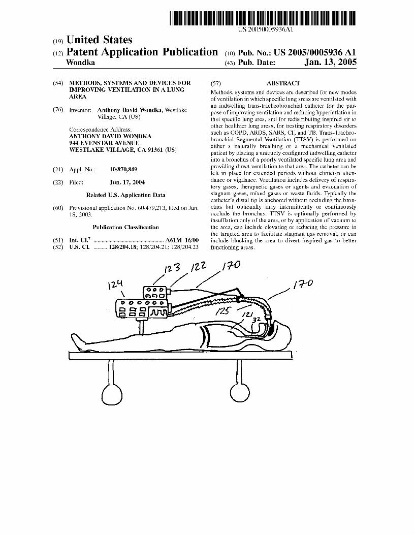
[0059] In FIG. 2 conventional therapies are shoWn Which enhance gas exchange of a compromised lung. FIG. 2a shoWs mechanical ventilation in conjunction With Transtra cheal Gas Insu?ation (TGI) using an EndoTracheal Tube 80. Positive pressure is delivered to the lung via a mechanical ventilator and EndoTracheal Tube and the trachea 32 is insuf?ated With oxygen 81 via a dedicated lumen 84 in the EndoTracheal Tube to ?ush out retained CO2 in the trachea. This therapy does not address the stagnant gas in the hyperin?ated lung areas that compromise ventilation. FIG. 2b shoWs long term oxygen therapy (LTOT) Where oxygen 81 is delivered via nasal cannula 82. Again, While increasing O2 levels in the lung’s upper airWays, this therapy does not address the stagnant gas in the hyperin?ated lung areas that compromise ventilation. FIG. 2c shoWs transtracheal oxy gen therapy (TTOT) Wherein oxygen 81 is delivered directly into the trachea 32 via a tracheotomy 83. While slightly more effective than LTOT, TTOT still has the same inherent shortcomings noted.
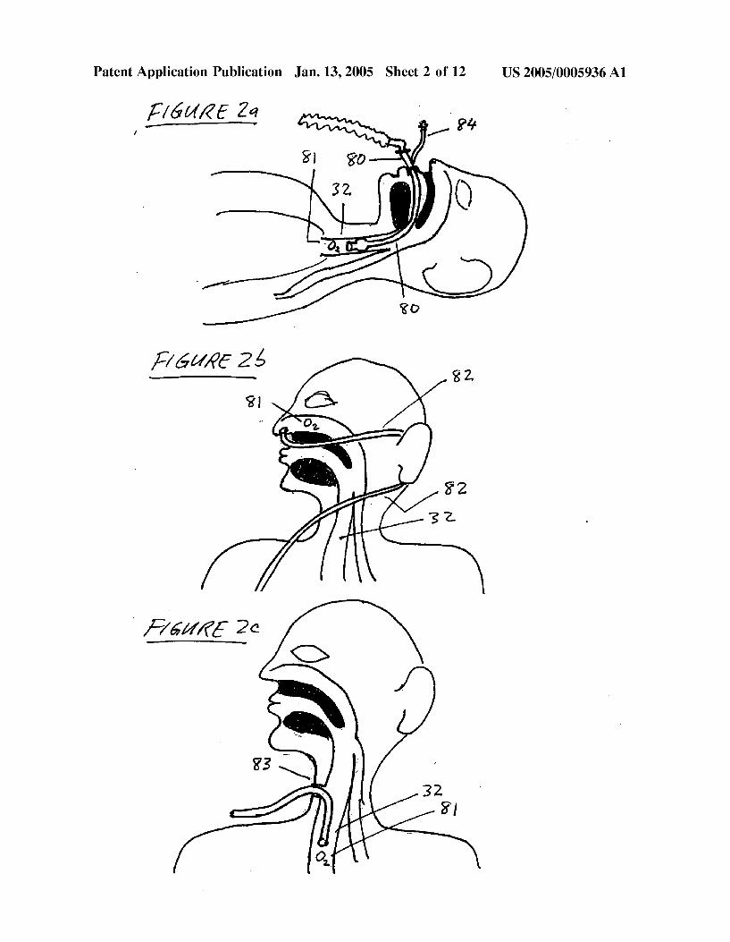
[0060] FIG. 3 describes a general layout of the invention disclosed herein, Wherein TTSV or TTSS is performed on an ambulatory spontaneously breathing patient, shoWing per cutaneous access into the trachea 32, catheteriZation of the targeted lung area 100, distal end anchoring 101, entry of the catheter 170 either nasally 102 or through a percutaneous incision 103, connection of the proximal end of the catheter to the Wearable portable Gas Control Unit 104, in the case of TTSV therapy. Referring to FIG. 3b a cross-sectional vieW is shoWn of entry of the catheter into the patient shoWing a percutaneous connector 105 With a through-port and hygienic seal 106 and a securing means 107 fastening the seal to the neck of the patient. The hygienic seal 106 also prevents inadvertent unWanted axial movement of the cath eter but alloWs desired axial sliding of the catheter in response to anticipated patient movement. The seal can be left in place to temporarily seal the incision With a self
US 2005/0005936 A1
sealing membrane or by attaching a plug 108 if the catheter is removed for extended periods.
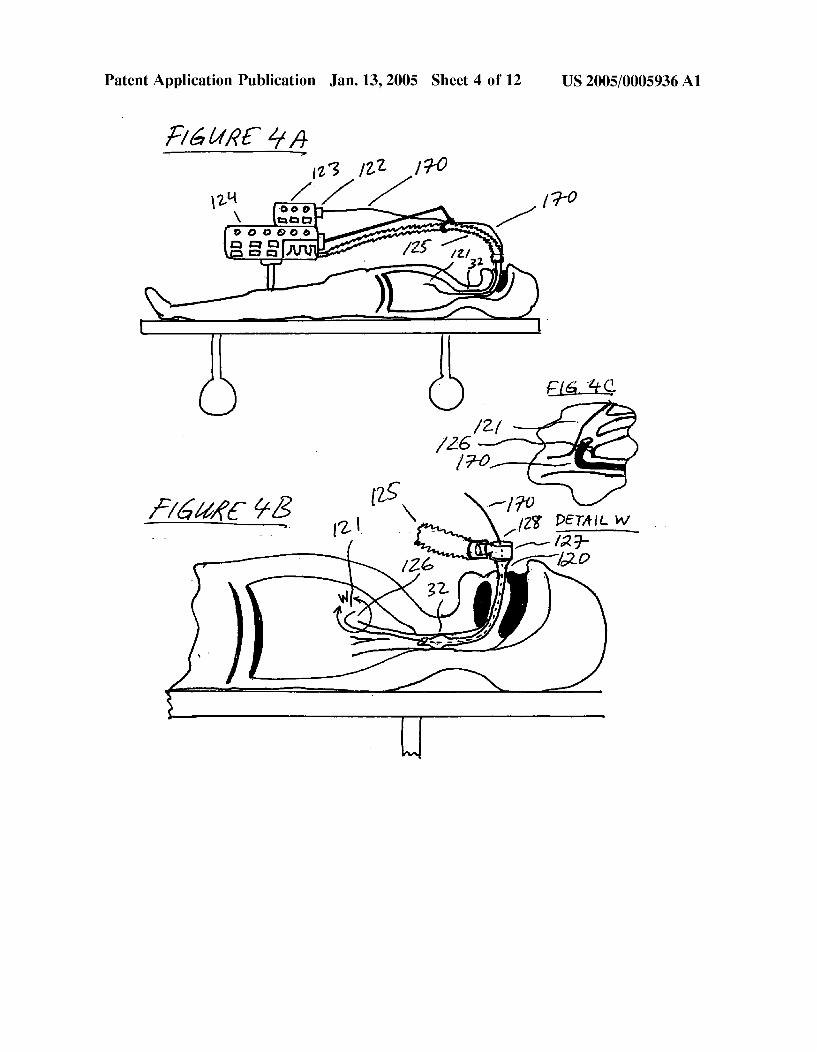
[0061] FIG. 4 describes a general layout of the invention, Wherein TTSV or TTSS is performed on a ventilatory dependent patient, shoWing entry of the catheter 170 through an endotracheal tube 120 Which is in the trachea 32 of the patient, catheteriZation of the targeted lung area 121, con nection of the proximal end of the catheter 122 to the ventilation Gas Control Unit 123, in the case of TTSV, as Well as the ventilator 124 and breathing circuit 125. It can be seen that the catheter distal end is anchored 126 in the targeted bronchus and the catheter shaft at the patient entry point near the elboW connector 127 is tensioned 128 to prevent inadvertent unWanted movement With a tensioning and/or sealing means.
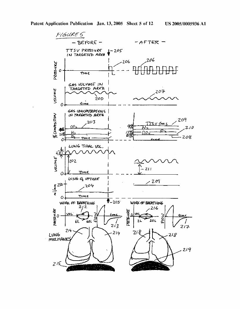
[0062] FIG. 5 graphically describes the effect of TTSV therapy performed on a naturally breathing patient. At baseline conditions the targeted lung area has an elevated gas volume 200 and the total lung has a tidal volume 201 With elevated residual volume 202. Due to gas trapping the targeted area has a predominant concentration of CO2 rich203 stagnant gas With very little fresh CO2 coming from the blood stream, loW blood perfusion due to shunting of blood to other lung areas, knoWn as the Euhler re?ex, and loW O2 uptake 204. Work of breathing pressure-volume curves 212 of a breath indicate gas trapping and labored inspiration and exhalation. Breath air flow indicates a pro tracted exhalation 213 due to the poor lung elastic recoil. The lung itself has hyperin?ated upper lobes 214 and diaphragm displaced doWnWard 215. TTSV is commenced 205 by site-speci?c ventilation 206 of the targeted area, typically using 100% Oxygen or HeliOx or some other therapeutic gas delivered through the indWelling TTSV catheter. After therapeutic equilibrium, the targeted area gas volume is decreased 207, the native stagnant gas concen tration in the targeted area is reduced dramatically 208 and is replaced by a high concentration of therapeutic gas 209 and fresh CO2 from the blood stream 210. Further, total lung residual volume decreases toWards normal 211, O2 transfer increases 209 toWards the normal value of 250 ml/min, Work of breathing is less labored 216 and exhalation flow rate returns quickly to Zero 217 due to improved recoil. The lung itself is less hyperin?ated 218 and the diaphragm position returns toWard normal 219. Depending on the parameters selected and other clinical factors, the therapeutic conditions can reach equilibrium in 30 minutes to 72 hours
[0063] FIG. 6 graphically describes the effect of TTSS therapy performed on a mechanically ventilated patient. At baseline conditions the tidal volume in the lung 250 shoWs an elevated residual volume 251 and the volume in the loWer lobes is abnormally loW 252. Work of breathing shoWs poor or high lung compliance 259 in ml/cmH20, and the overall gas exchange is comprised 253. The lung itself is hyperin ?ated, especially the upper lobes 260 and the diaphragm is displaced doWnWard 261. After commencement of TTSS therapy the conditions begin to change due to the blocking of the targeted area by the blocking catheter, and optionally enhanced by applying a slight vacuum to the blocked area via the catheter. Due to absorption of the gas in the blocked area, or dissipation of the gas out of collateral channels, or by slight vacuum applied via the catheter, the volume in the targeted area decreases as does the overall lung volume 254 and lung residual volume 255. Some inspired gas volume is
Jan. 13, 2005
noW diverted to the loWer lobes 256, the lung compliance noW decreases to a more healthy or elastic level 257 as
shoWn by the pressure-volume curve of a breath, gas transfer returns to a more normal level 258, and the lung itself is less hyperin?ated 262 and the diaphragm returns to a more normal position 263. Equilibrium can be reached betWeen 30 minutes and 72 hours, depending on the targeted area blocked and other clinical conditions.
[0064] FIG. 7 graphically describes optional TTSV ven tilation parameters With the abscissa and vertical coordinates corresponding to time and TTSV catheter pressure. FIG. 7a shoWs intermittent gas delivery With on 300 and off 301 times. FIG. 7b shoWs intermittent gas removal 302 by suctioning. FIG. 7c shoWs alternating gas delivery 303 and gas suctioning 304. FIG. 7a' shoWs alternating gas delivery and suctioning synchroniZed With the breath cycle so that TTSV gas delivery 305 occurs during the inspiratory phase 306 and TTSV gas removal 307 occurs during the expiratory phase 308. FIG. 76 shoWs TTSV gas removal 309 synchro niZed With inspiration 306 and TTSV gas delivery 310 synchroniZed With exhalation 308. FIG. 7f shoWs changing levels and periods of TTSV gas delivery 311 and gas suctioning 312 Wherein the levels are changing in order to maintain the desired conditions in the targeted area. FIG. 7g shoWs high frequency oscillatory gas delivery 313 and gas suctioning 314. FIG. 7h shoWs constant or static gas deliv ery 315 concurrent With high frequency oscillatory gas suctioning 316. FIG. 7i shoWs high frequency oscillatory gas delivery 317 concurrent With constant or static gas suctioning 318. FIG. 7j shoWs constant gas delivery 319 Without any gas suctioning. FIG. 7k shoWs constant gas delivery 320 concurrent With intermittent gas suctioning 321. FIG. 7l shoWs concurrent constant gas delivery 322 and gas suctioning 323. FIG. 7m shoWs variable gas deliv ery periods 324 and amplitudes 325 in order to regulate the desired conditions in the targeted area. FIG. 711 shows constant or static vacuum 326 applied to the targeted lung area With out any gas delivery. FIG. 70 shoWs alternating gas delivery and gas suctioning With a short delivery phase 327 and extended vacuum phase 328.
[0065] Typical gas delivery and gas suction parameters depend on the area being treated and the clinical conditions. During mechanical ventilation, gas delivery can range from 0.1 to 1.5 lmp and 8 to 40 cmH2O at the lobar segment level and 1.0 to 10.0 lmp and 10 to 50 cmH2O at the tracheal level. Gas evacuation can range from 0.1 to 1.5 lmp and —5 to —40 cmH2O at the lobar segment level and 1.0 to 10.0 lmp and —10 to —50 cmH2O at the tracheal level. During spontaneous ventilation, How can range from 0.05 to 1.5 lmp and 3 to 20 cmH2O at the lobar segment level and 1.0 to 10.0 lmp and 5 to 30 cmH2O at the tracheal level. Gas evacuation can range from 0.05 to 1.5 lmp and —3 to —20 cmH2O at the lobar segment level and 1.0 to 10.0 lmp and —5 to —30 cmH2O at the tracheal level. Frequencies can range from 1 to 120 cycles per hour if being used intermittently, and 2 to 120 cycles per minute in oscillatory mode, and 1 hour to inde?nite durations for continuous mode.
[0066] FIG. 8 describes a typical TTSV catheter 170 With a catheter shaft 180 a distal end 181, a proximal end 182, a proximal end connector 176 for attachment to the TTSV Gas Control Unit, connection ports for insuf?ation How 175 and suction 176, a distal end anchoring member 173, a slide-able sleeve 177 for placement in the percutaneous incision With

US 2005/0005936 A1
a self-sealing gasket 179, a connection 178 for detachment of the proximal end of the catheter, a sleeve 174 for compressing the anchoring member 173, a mechanism 169 for retracting the sleeve 174, a lumen 168 for the mechanism 169, a lumen for gas delivery 171 and a lumen for gas suctioning 172.
[0067] FIG. 9 describes typical TTSS catheter con?gura tions. FIG. 9a shoWs a dual TTSS catheter device, each catheter comprising a shaft 150, a balloon 151, for sealing at the distal tip of the catheter, a connector at the proximal end 152 of the catheter for optional connection to a suction source, a port 153 for in?ation of the balloon, a through lumen 154 throughout the length of the catheter for guideWire insertion or for applying suction through the catheter, a 15 mm sWivel elboW connector 155 for attach ment to an endotracheal tube 156 and breathing circuit 157 and a port 158 for insertion of a bronchoscope if needed.
[0068] FIG. 9b shoWs a dual TTSS catheter integrated into the construction of an endotracheal tube 160. The TTSS catheters are slide-able Within lumens 161 and 162 in the Wall of the endotracheal tube. The catheters include con nectors 163 for in?ation of the occlusion balloons 164.
[0069] FIG. 10 describes alternate TTSV or TTSS cath eter systems, devices and con?gurations. FIG. 10a shoWs a catheter With a self expanding Woven Wire anchor 400 Which expands upon retraction of an outer sleeve 401 concentric to the catheter shaft 402. The catheter includes lumens for gas delivery 403 and gas removal 404. FIG. 10b shows a catheter With an in?atable balloon 405 Which serves as an anchor and a bronchial occluder. The balloon is either electively in?atable, or is normally in?ated and electively de?atable. FIG. 10c describes an in?atable anchor 407 in the shape of radial spokes 408 and hence anchors the catheter tip but does not occlude the bronchus. FIG. 10d describes a catheter With both an occlusive balloon 410 and a non-occlusive anchor 411. FIG. 106 shows a catheter With an in?atable balloon anchor 414 and in Which the catheter includes a large port 415 communicating With a lumen 416 such that the anchor does not occlude the bronchus. Gas is free to ?oW betWeen the treated area 417 and the proximal areas 418 to avoid the clinical problems of complete bron chial obstruction. FIG. 10f describes a catheter anchor comprised of Wire loops 420. FIG. 10g describes a catheter With multiple small lumens 422 for gas delivery and a large lumen for gas suctioning 423. FIG. 10h shoWs a dual lumen catheter comprised of tWo concentric tubes 425 and 426 forming an inner lumen 427 and annular lumen 428, Wherein the inner tube or lumen is recessed from the catheter tip. Suctioning is conducted through the annular lumen and gas delivery through the inner lumen such that the gas delivery can prevent clogging of the suctioning path by ?ushing out any debris 429. FIG. 10i describes a tri-lumen catheter With a lumen 432 for passage of a guideWire 433 Wherein the guideWire may comprise a compressible anchoring feature 434 that can be retracted into the catheter lumen. FIG. 10j shoWs a dual lumen catheter in Which the tip has been shaped to bend one lumen 440 180° such that the end of the lumen 441 points proximally aWay from the targeted lung area 442. Positive pressure is applied to the proximal end of this lumen to create a high velocity jet 443 at the distal port 441. The jet entrains gas in the targeted area 444 to be sucked out With the jet due to the venturi effect and thus alloWs for suctioning of gas but Without the risk of clogging
Jan. 13, 2005
the catheter With debris. FIG. 10k describes another venturi system in Which the tip of the catheter is con?gured such that positive pressure gas ports 450 are pointed proximally. High velocity gas exiting these ports 451 entrain gas in the targeted area 452 to be sucked out With the jet. These venturi con?gurations are especially useful in applications Where gas removal is critical to the therapy and Where there is a risk of catheter clogging if vacuum Where to be used.
[0070] FIG. 11 describes a catheter exchange system Wherein the catheter is placed over a guideWire and can be disconnected. The proximal section 480 or machine end Which remains external to the patient, includes a connector 481 for connection to a TTSV ventilation control unit and a connector 482 for removal of the proximal section from the distal section 483. The distal section 483 or patient end Which is predominantly inside the body, includes a receiving connector 485 for the proximal end and a slide-able sleeve 486 for placement in the percutaneous incision. The sleeve self-seals on the shaft of the catheter 487 and applies a slight amount of tension to the catheter shaft to prevent inadvertent dislodgment of the catheter from the lung. The sleeve also includes Widenings 488 on both ends to anchor it in place on both sides of the incision. The distal section of the catheter also includes a stretchable section of catheter tubing 489 such that during movements of the patient’s neck, the catheter length can change Without transferring undesired tension to the distal end and inadvertently dislodging the catheter. Also included is a guideWire 490 that can be inserted and removed from a lumen 491 in the catheter, in order to initially place the catheter into the targeted site, or to place in the targeted site While the catheter is being removed, for example for cleaning or replacement.
[0071] Typical diameters of the TTSV catheter depend on the lung area being targeted. Some exemplary dimensions folloW: Lobar segment: OD=2.0-3.5 mm; Lobar subseg ment: OD=1.5-2.5 mm; Lobar sub-subsegment: OD=0.5-1.0 mm. TTSV catheter gas insuf?ation lumen diameters are typically 0.25-1.0 mm and gas exhaust lumens, if separately present, are typically comprise an area of 0.8-4.0 mm2, preferably greater than 2.0 mm2 to avoid mucous plugging. Catheter lengths are typically 120-150 cm. Anchoring forces are typically 1-10 psi and occlusion forces, if occlusion is utiliZed, are typically 0.2-0.5 psi. Anchors and occlusive member diameters depend on the targeted bronchial level and are up to 25 mm for main stem bronchus cannulation, 20 mm for lobar bronchus cannulation, 12 mm for segmental bronchi and 3 mm for sub-subsegmental bronchi cannulation When fully expanded. Proximal entry point tensioning forces typically produce 0.5-1.5 lbs of axial tension. The percuta neous plug is typically a soft rubber or thermoset material such as silicone. Some examples of catheter materials are; the shaft extrusion typically comprised of a thermoplastic or thermoset material such as nylon, PVC, polyethylene, PEBAX or silicone; the non-occlusive anchor typically comprised of a stainless steel or Nitinol Wire; the in?atable occlusive member comprised of a highly compliant plasti sol, silicone or urethane; connectors typically comprised of PVC, polysulfone, polypropylene or acrylic.
[0072] FIG. 12 describes a method and apparatus to alloW the indWelling TTSV or TTSS catheter to remain in place for extended periods Without irritating the bronchial Walls and optionally to prevent dislodgment of the catheter during movement of the neck. FIG. 12a describes compressible