Methods of the Circuit Analysis - die.ing.unibo.it · 3 As two inputs contribute to the operation...
15
1 ! Topology Equations (r equations) (KCL: n-1 equations) (KTL: r-n+1 equations) ! Element Equations (r equations) The number of these equations is equal to the number of the branches as they are the equation modeling each element of the circuit, and hence any branch. The circuit analysis problem is described by 2r equations in 2r unknowns. The equations are the topology equations and the element equations. The unknowns are the branch tensions and the branch currents. Circuit with n nodes and r branches ! ! = = m r n r 0 v 0 i Methods of the Circuit Analysis Department of Electrical, Electronic, and Information Engineering (DEI) A University of Bologna General method i1 + i3 + i4 -i6 = 0 i2 -i3 -i4 + i5 = 0 i6 -i5 = 0 -v1 + v2 + v3 = 0 -v 1 + v 2 + v 4 = 0 v1 -v2 + v5 + v6 = 0 v1 = V0 v2 = R2 i2 v3 = R3 i3 v 4 = R 4 i 4 + V 1 v5 = R5i5 v6 = R6i6 Top.Eq.s Elem.Eq.s Circuit: r = 6, n = 4 The circuit is described by 12 linear non4homogeneous equations and 12 unknowns. Therefore it has a unique solution. Example Methods of the Circuit Analysis • • • • B C _ H G E F _ _ _ D A 2 1 5 6 4 3 Graph Department of Electrical, Electronic, and Information Engineering (DEI) 6 University of Bologna A B C D H G E F i 1 i 2 i 6 i 4 i 3 i 5 V0 V1 R2 R6 R5 R3 + " • • • • • B C _ " + - H G E F _ _ _ R4
Transcript of Methods of the Circuit Analysis - die.ing.unibo.it · 3 As two inputs contribute to the operation...

1
! Topology(Equations( (r equations)
(KCL: n-1 equations)
(KTL: r-n+1 equations)
! Element(Equations((r equations)The$number$of$these$equations$is$equal$to$the$number$of$the$branches$as$they$are$the$equation$modeling$each$element$of$the$circuit,$and$hence$any$branch.$
The$circuit$analysis$problem$is$described$by$2r$equations$in$2r$unknowns.$The$equations$are$the$topology$equations$and$the$element$equations.$The$unknowns$are$the$branch$tensions$and$the$branch$currents.
Circuit with n nodes and r branches
!!
=
=
m r
n r
0v0i
Methods of the Circuit Analysis
Department$of$Electrical,$Electronic,$and$Information$Engineering$(DEI)$A University$of$Bologna
General method
i1 + i3 + i4 - i6 = 0i2 - i3 - i4 + i5 = 0i6 - i5 = 0- v1 + v2 + v3 = 0- v1 + v2 + v4 = 0v1 - v2 + v5 + v6 = 0
v1 = V0v2 = R2 i2
v3 = R3 i3
v4 = R4i4 + V1
v5 = R5i5
v6 = R6i6
Top.Eq.s
Elem.Eq.s
Circuit:22r = 6, n = 4The$circuit$is$described$by$12$linear$non4homogeneous$equations$and$12$unknowns.$Therefore$it$has$a$unique$solution.$$$
H � G�E � F_ _ _
Example
Methods of the Circuit Analysis
••
•
•B � C_
H � G�E � F_ _ _
DA2
1
5
6
43
Graph
Department)of)Electrical,)Electronic,)and)Information)Engineering)(DEI))6 University)of)Bologna
A B C D
H G E F
i1
i2
i6i4
i3
i5
V0
V1R2
R6
R5
R3+"
• •• •
•
B � C_
"+
-
H � G�E � F_ _ _
R4

2
! General'Method'of'the'Circuit'Analysis:(r'branches,*2r'unknowns,*2r'equations)
! Method'of'the'Tension'Substitution:(r'branches,*r'unknowns,*r'equations)
k0,kkk
m k
n k
ViRv
0v0i
+=
=
=
!!
These%equations%are%for%a%generic%element%with%a%resistors%and%a%tension%source
!!
=+
=
m k0,kk
n k
0ViR0i
(n-1) eq.s
(r-n+1) e q.s
r eq.s
(n-1) eq.s
(r-n+1) eq.s
Methods of the Circuit Analysis
Department*of*Electrical,*Electronic,*and*Information*Engineering*(DEI)*> University*of*Bologna
Superposition+Principle:As#a#consequence#of#the#linearity#of#the#equations#which#describe#the#circuit#the#solution#of#the#equations#of#the#Tension#Substitution#Method#is#given#by#the#branch#currents#expressed#by#a#linear#combination#of#the#independent#sources#of#the#circuit.
ir = Gr1V01 + Gr2V02 + … + GrlV0l + αr,l+1I01 + αr,l+2I02 +…+ αr,gI0g
We#must#stress#that#this#is#only#valid#in#the#linear#case.#In#order#to#be#in#this#case,#the#element#equations#must#be#linear.
V0k and#I0k are#the#input#of#the#circuit,#ir is#an#output.##Usually#the#source#voltages#and#source#currents#are#the#inputs#of#the#circuit.#The#branch#voltages#and#branch#currents#are#the#outputs.
The#superposition#principle#states#that#any#branch#current#is#the#algebraic#sum#of#the#currents#through#the#branch#due#to#each#independent#source#acting#alone#(the#same#statement#holds#for#the#branch#voltages#also).#
Methods of the Circuit Analysis

3
As two inputs contribute to the operation of this circuit , their two contributions are considered separately to calculate the outputs (branch current and voltages). Firstly the circuit with the source V0 and I0 is switched off (I0 = 0 corresponds to an open circuit branch) is analyzed. Afterwards the circuit where V0 is switched (V0 = 0 corresponds to a closed circuit branch) and the only active source is I0.
Calculation of i3: i3 = i3’ + i3”
- To calculate i3’ when I0 = 0:( )
2
BG332BG
eq
010110BG
eq
01
432
4321eq01eq
R'v
'i 'i R 'v
RV
R - V 'i R V ' v RV
- 'i
RRR
RRRR R dove 0 V 'iR
=!=
=+=!=
"#
$%&
'+++
+==+
02
toteq
2
BG30
toteq
"4
toteqBG
Beq
Aeq
Beq
Aeqtot
eq43Beq
21
21Aeq
IR
R
R"v
"i I R i R "v
RR
RRR ;RR R ;
RRRR
R
==!="=
+=+=
+=
•A B C D
H G E F
i1
i2
i6i4i3
i5
V0 I0
R1
R4
R3
R2+"
B
i3’
V0
R1
R4
R3
R2
i1’
G
+"
B
G
i4”i3”I0
R1
R4
R3
R2
Example
- To calculate i3’’ when V0 = 0:
• •
•
• •
•
•
••
•
! The$method$is$based$on$the$node%voltages,$uk (k=$1,2,..,n61),$that$are$the$potential$differences$between$each$non6reference$node$and$the$reference$node$(ground).$Hence$each$node$voltage$is$the$voltage$of$that$node$with$respect$to$the$reference$node." KCL$$is$applied$to$each$non6reference$node$k,$k$=$1,2,…,$n61$(figure$above):
i1+i2+….+ih = 0 (1)" KTL$is$applied$to$relate$the$node$voltages$to$the$branch$voltages$(figure$below):
vr = uk-uh (2)
" The$currents$are$expressed$by$the$element$equations
(3)
" By$substituting$eq.$3$into$eq.$1$a$set$of$n61$equations$in$n61$unknowns$(uk,$for$k=1,2,…,$n61)$is$obtained.
Methods of the Circuit Analysis
This method is utilized in the AC regime where Ir , Uk and Zr replaces ir ,vr , and Rr .
r
hk
r
rr R
uuRvi !
==
Nodal Analysis (n"1$$equations,$n"1$unknowns)
k1h
32
uh
+6vr
h k
uk0
•
•
• •
•
•
• •

4
Methods of the Circuit Analysis
! The$n&1$node$voltages$are$determined$by$the$solution$of$a$linear$non&homo&geneous$system$of$n&1$equations.$As$the$node$voltages$are$known,$the$branch$currents$are$obtained$from$eq.$3$and$the$branch$voltages$are$derived$from$eq.$2.
Nodal Analysis (n"1$$equations,$n"1$unknowns)
Step$to$determine$the$node$voltages1.//Define/the/reference/node/and/assign/the/n71/node/voltages/which/are/the/voltage/of/the/non7reference/nodes/with/respect/to/the/reference/one.
2.///Apply/KCL/to/each/non7reference/node.3.///Apply/KTL/to/refer/the/node/voltages/to/the/branch/voltages.
4. Express/the/branch/currents/in/terms/of/the/node/voltages/through/the/element/equations/and/substitute/them/in/the/cur7rents/equations/given/by/KCL/in/step/2./
5.///Solve/the/resulting/simultaneous/equations/to/obtain/the/node/voltages.
k1h
32
uh
+&vr
h k
uk0
•
• •
• •
•
•
•
v2 = u1v3 = u2
v4 = u2 - u1
i1 = - I1i5 = I2
v2 = R2 i2
v3 = R3 i3
v4 = R4 i4
i1 = - I1i5 = I2
i1 = - I1
i2 = u1 /R2
i3 = u2 /R3
i4 = (u2 - u1) /R4i5 = I2
!!"
!!#
$
=%%
+
=+%
%+%
0IRuu
Ru
0IRuu
RuI
24
12
3
2
24
12
2
11
!"#
=$+=+$+
0 i i i 0 i i i i
543
5421
( ) ( )( )!
"#
=++$$=$+
24323413
214222142
IRRuRRuRIIRRuRuRR
i1i4
i3i2
i5
I1
R4
R3R2
0
u1 u2
I2
Example
2. KCL application 3. KTL application
4. Use of element eq.s
ir as function of uk
ir expressed by uk in KCL eq.s
5. Solution of KCL eq.s in ukunknown (2 q.s and 2 unknowns)
1. Reference node definition
•
••
Department)of)Electrical,)Electronic,)and)Information)Engineering)(DEI))6 University)of)Bologna

5
i1 i6i4i3
i5
V0 I0
R1
R4
R3
R2+"
0
u1 u2
v1 = u1v3 = u1v4 = u1
v5 = u2 - u1
v6 = - u2
v1 = V0 + R1 i1
v3 = R2 i3
i4 = - I0
v5 = R3i5v6 = R4i6
i1 = (u1 - V0)/ R1
i3 = u1 /R2
i4 = - I0
i5 = (u2-u1)/ R3
i6 = - u2/R4
!"#
==++
0 i - i0 i - i i i
65
5431
( )( )!"
!#$
=%+%
+=%++
0uRRuR
VRRIRRRuRRuRRRRRR
23414
032023212211213231
1. Reference node definition
Example
2. KCL application
3. KTL application 4. Use of elem. eq.s ir as function of uk
ir expr. by uk in KCL eq.s5. Solution of KCL eq.s in ukunknown (2 q.s and 2 unknowns)
•
•
••
Department)of)Electrical,)Electronic,)and)Information)Engineering)(DEI))6 University)of)Bologna
!!"
!!#
$
=+%
=%
%%++
0Ru
Ruu
0RuuI
Ru
RVu
4
2
3
12
3
120
2
1
1
01 -
In#the#circuit#there#are#branches#that##contain#only#voltage#sources#(independent#or#controlled#sources).#For#these#branches#the#currents#cannot#be#expressed#in#terms#of#the#voltages.#A#branch#with#only#a#voltage#source#can#be##incorporated#into#a#closed#surface.#Thereafter#KCL#is#applied#to#this#surface.#This#branch#is#said#supernode.#As#it#results#from#KTL,#the#difference#of#the#node#voltages#at#the#terminals#of#the#source#branch,#is#given#by#the#source#voltage:
uk-uh = V0
!"
!#$
==+
=++
032
5432
541
Vu-u0 i-i -i i
0 i i i
• •
i4
i2
R4
R2
0
u2 u3
i3
R3
-+
V0u1 i5 R5
i1
R1
By expressing the 5 currents by means of the 3 node voltages, the system of equations is given by three equations with three unknowns which are the node voltages.
Nodal AnalysisSupernode
•
•••
Department-of-Electrical,-Electronic,-and-Information-Engineering-(DEI)-8 University-of-Bologna

6
When%%supernode%contains%the%reference%node%the%voltage%of%the%non4reference%node%inside%the%supernode%is%given%by%the%source%voltage:
uk = V0!"
!#
$
==+%=++
02
432
541
Vu0 i i i0 i i i
• •
i4 R4
0
u2 u3
i3
R3V0
u1 i5 R5
i1
R1 +-
i2R2
Nodal AnalysisSupernode
In this case also by expressing the 5 currents by means of the 3 node voltages, the system of equations is given by 3 equations with three unknowns which are the node voltages.
• •
•
•
Department)of)Electrical,)Electronic,)and)Information)Engineering)(DEI))6 University)of)Bologna
!!"
!!#
$
=%=%
=+%%=++
543
21
5432
521
i9uu02uu
0 ii i i0 10-i i i
•
i5
0
u2 u3u1
3Ω
i1 i34Ω
i2
i41Ω
6 Ω-+-+
u4
10!
3 v520V
i1 = u1/2i2 = (u2-u3)/6i3 = u3/4i4 = u4/1i5 = (u1- u4)/3
!!!!
"
!!!!
#
$
%=%
=%
=%
+%%%
=%
+%
+
3uu9uu
20uu
03uu
1u
4u
6uu
103uu
6uu
2u
4143
21
414332
41321
!!"
!!#
$
=%%=%
=%%+=%%+
0u2u3u20uu
0u8u5,2u2u60u2uu5u
431
21
4321
4321
2Ω
Example
•• ••
•
Department)of)Electrical,)Electronic,)and)Information)Engineering)(DEI))6 University)of)Bologna
7
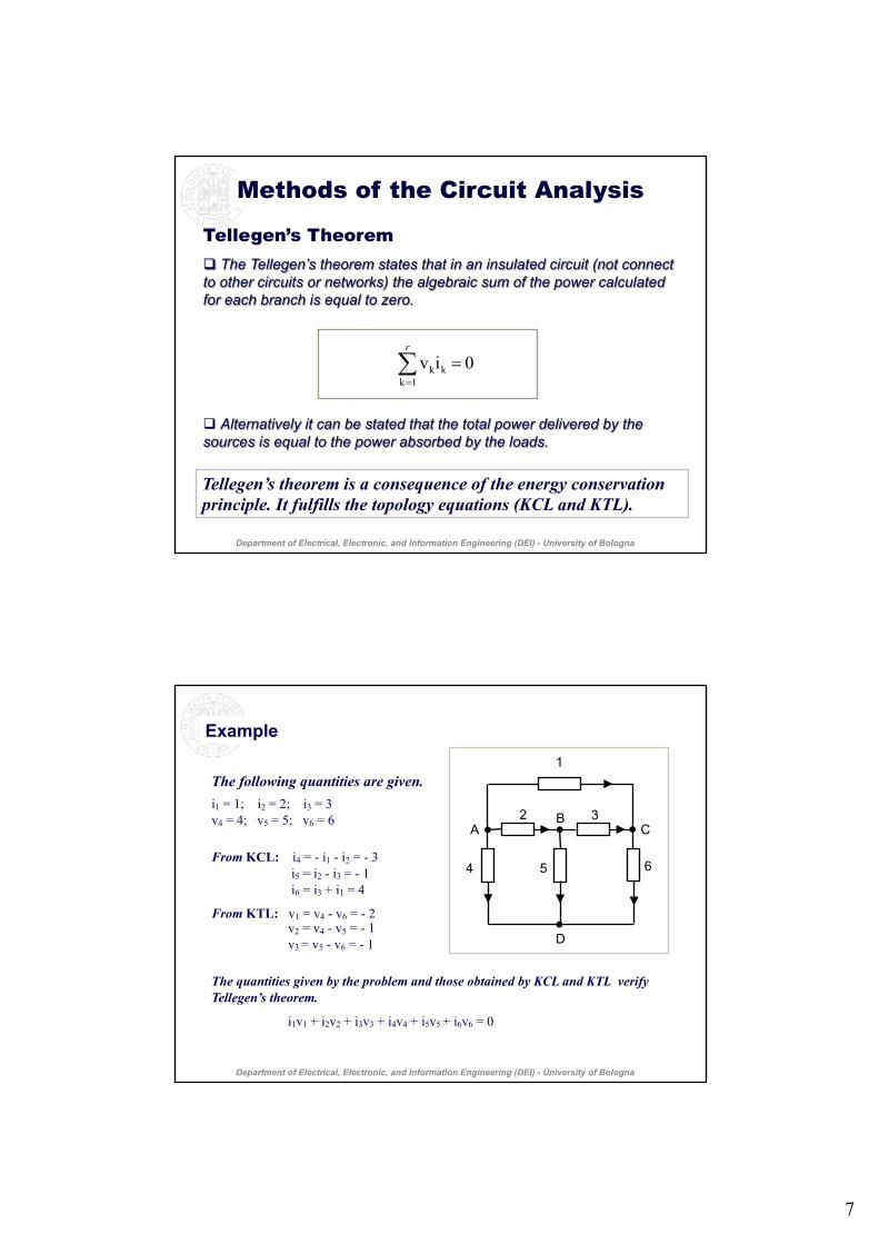
Tellegen’s Theorem! The$Tellegen’s theorem$states$that$in$an$insulated$circuit$(not$connect$to$other$circuits$or$networks)$the$algebraic$sum$of$the$power$calculated$for$each$branch$is$equal$to$zero.
! Alternatively$it$can$be$stated$that$the$total$power$delivered$by$the$sources$is$equal$to$the$power$absorbed$by$the$loads.
0 iv 1k
kk =!=
r
Tellegen’s theorem is a consequence of the energy conservation principle. It fulfills the topology equations (KCL and KTL).
Methods of the Circuit Analysis
Department)of)Electrical,)Electronic,)and)Information)Engineering)(DEI))6 University)of)Bologna
•
• • •AB
C
D
1
2 3
4 5 6
The following quantities are given.i1 = 1; i2 = 2; i3 = 3v4 = 4; v5 = 5; v6 = 6
From KCL: i4 = - i1 - i2 = - 3i5 = i2 - i3 = - 1i6 = i3 + i1 = 4
From KTL: v1 = v4 - v6 = - 2v2 = v4 - v5 = - 1v3 = v5 - v6 = - 1
The quantities given by the problem and those obtained by KCL and KTL verify Tellegen’s theorem.
i1v1 + i2v2 + i3v3 + i4v4 + i5v5 + i6v6 = 0
Example
•
• • •
Department)of)Electrical,)Electronic,)and)Information)Engineering)(DEI))6 University)of)Bologna

8
In Out
=Out$$F$ $In
Methods of the Circuit Analysis
The transfer function can be defined in the time domain [voltages and currents: v(t) and i(t)], in the frequency domain [voltages and currents: V and I ] or in the Laplace transform-domain.
Transfer FunctionIn#a#circuit#we#will#distinguish#between#input& and##output.#The#inputs#are#the#independent#current#and#voltage#sources,#also#said#excitations.#The#output#are#the#branch#currents#and#the#tensions#(branch#voltages,#node#voltages#or#any#potential#difference#between#two#nodes).
In#a#linear,#time#independent#circuit#for#an#input=output#pair#a#transfer&function&(or#network&function)#is#defined.#The#transfer#function#is#the#ratio#between#an#output#and#an#input#when#the#other#sources,#except#the#one#considered,#are#switched#off.##
Linear,,time.independent
network
Department&of&Electrical,&Electronic,&and&Information&Engineering&(DEI)&; University&of&Bologna
As#it#had#been#stated#by#the#superposition#principle,#in#a#linear#circuit#any#voltage#vrand#any#current#is can#be#expressed#as#a#linear#combination#of#the#p independent#tension#sources#and#the#q independent#current#sources#:
vr =# αr1 V01 +#αr2 V02 +#….#+#αrp V0p +#Rr1 I01 +#Rr2 I02 +#….#+#Rrq I0qis =#Gs1 V01 +#Gs2 V02 +#….#+#Gsp V0p +#βs1 I01 +#βs2 I02 +#….#+#βsq I0q
The#coefficients#αri,#Rrj,#Gsi,#βsj are#the#transfer#functions#of#the#r voltages#and#the#stensions#when##coupled#two#by#two#to#the#p tension#sources#and#the#q current#sources.#The#transfer#functions##αri and#βsj are#dimensionless.##The#Rrj have#the#dimension#of#a#resistance#or#an#impedance#(Ω).#The#Gsi have#the#dimension#of#a#conductance#or#an#admittance#(S#=#1/Ω).
Voltage Gain: αrp = vr
V0p V0i = 0 per i≠pI0j = 0 ∀ j
Transf. Imped.: Rrq = vr
I0q V0i = 0 ∀ iI0j = 0 per j ≠ q
Transf. Admitt.: Gsp = is
V0p V0i = 0 per i≠pI0j = 0 ∀ j
Current Gain: βsq = isI0q V0i = 0 ∀ i
I0j = 0 per j ≠ q
Transfer Function
Department)of)Electrical,)Electronic,)and)Information)Engineering)(DEI))6 University)of)Bologna

9
A"circuit"N+N1 is"constituted"by"the"circuit"N"and"the"circuit"N1 connected"through"a"port."The"circuit"N"is"linear,"time;independent"(time"independent"properties"of"itacircuit"elements),"with"stationary"sources."The"circuit"N"is"connected"to"the"circuit"N1 through"the"port"AB.""For"a"given"value"of"the"voltage"v of"port"AB"the"current"iflowing"from"A"to"B"through"N"is"determined"by"the"characteristics"of"the"circuit"N."The"v;i relation,"as"an"uniqu element"equation"of"circuit"N,"can"be"determined.
Hence"the"one"port"circuit"N,"characterized"by"i and"v,"can"be"considered"a"two"terminal"element."This"can"be"done"even"if"the"circuit"N"is"constituted"by"many"circuit"elements."The"i-v relation"only"depends"on"N."The"determination"of"this"relation"is"the"equivalent*circuit*determination"problem.
Methods of the Circuit Analysis
Circuit'N1
•
A
B
v
iCircuit'NLinear,'time0independentnetwork'with'stationary'sources
•
Department*of*Electrical,*Electronic,*and*Information*Engineering*(DEI)*9 University*of*Bologna
Equivalent Circuits
Equivalent Circuits
The$problem$of$the$equivalent*circuit*determination$is$to$find$an$elementary$circuit,$the$operation$of$which$simulates$the$operation$of$the$circuit$N.$For$this$elementary$circuit,$that$is$the$equivalent$circuit,$at$a$given$voltage$v the$same$current$i flows$through$it$as$it$would$flows$through$the$circuit$N$when$the$voltage$v between$the$terminals$A$and$B$would$be$the$same.$$
Methods of the Circuit Analysis
•
A
B
v
iCircuit'NLinear,'time/independentnetwork'with'stationary'sources
•
This$problem$is$solved$by$the$Thévenin’s theorem$and$by$the$Norton$theorem.$The$$equivalent$Thévenin circuit is$constituted$by$the$series$of$an$independent$voltage$source$with$a$resistor.$
The$$equivalent$Norton*circuit*is$constituted$by$the$parallel$of$an$independent$current$source$with$a$resistor.
Department*of*Electrical,*Electronic,*and*Information*Engineering*(DEI)*= University*of*Bologna
10
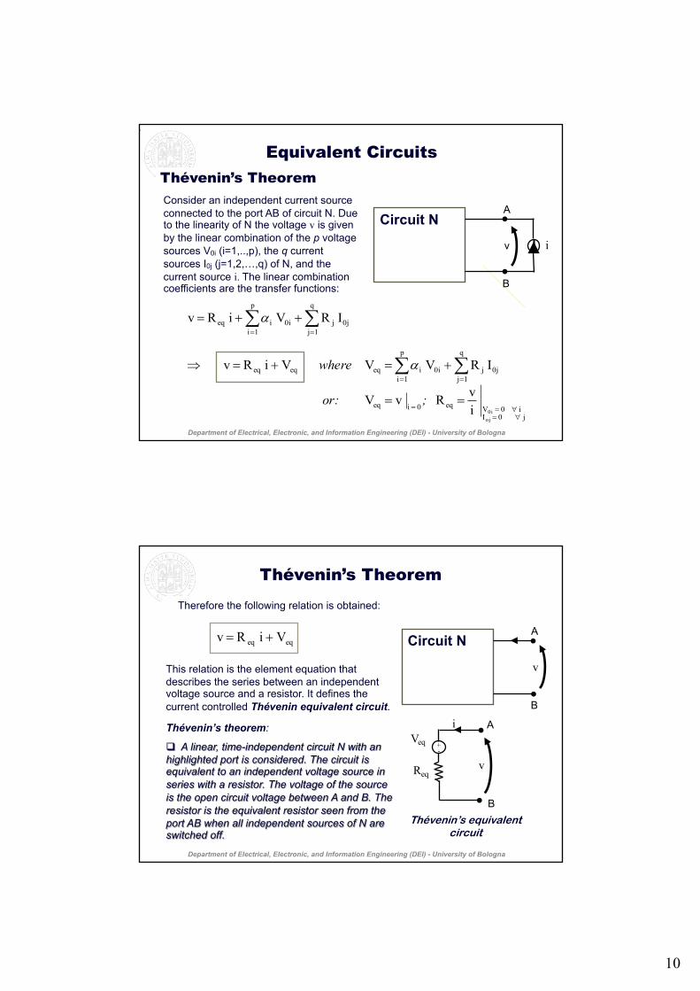
Consider)an)independent)current)source)connected)to)the)port)AB)of)circuit)N.)Due)to)the)linearity)of)N)the)voltage)v is)given)by)the)linear)combination)of)the)p voltage)sources)V0i (i=1,..,p),)the)q current)sources)I0j (j=1,2,…,q))of N,)and)the)current)source)i. The)linear)combination)coefficients)are)the)transfer)functions:
j 0 Ii 0 Veq0 ieq
q
1j0jj
p
1i0iieqeqeq
q
1j0jj
p
1i0iieq
oj0i
iv R v V
I R V V V i R v
I R V i R v
!=!==
==
==
==
+=+="
++=
##
##
;or:
where $
$
Equivalent CircuitsThévenin’s Theorem
•
•
A
B
v i
Circuit'N •
Department)of)Electrical,)Electronic,)and)Information)Engineering)(DEI))6 University)of)Bologna
Therefore'the'following'relation'is'obtained:'
This'relation'is'the'element'equation'that'describes'the'series'between'an'independent'voltage'source'and'a'resistor.'It'defines'the'current'controlled'Thévenin equivalent-circuit.
Thévenin’s theorem:
! A#linear,#time-independent#circuit#N#with#an#highlighted#port#is#considered.#The#circuit#is#equivalent#to#an#independent#voltage#source#in#series#with#a#resistor.#The#voltage#of#the#source#is#the#open#circuit#voltage#between#A#and#B.#The#resistor#is#the#equivalent#resistor#seen#from#the#port#AB#when#all#independent#sources#of#N#are#switched#off.#
Thévenin’s Theorem
eqeq V i R v +=
Req
Veq•
• B
A
v
i
+-
Thévenin’s equivalentcircuit
•
•
A
B
v
Circuit'N
Department-of-Electrical,-Electronic,-and-Information-Engineering-(DEI)-> University-of-Bologna

11
j 0 Ii 0 Veq0 veq
q
1j0jj
p
1i0iieqeqeq
q
1j0jj
p
1i0iieq
oj0i
vi G i I
I V G I I vG i
I V G vG i
!=!==
==
==
==
+=+="
++=
##
##
;or
where $
$
Norton’s TheoremConsider)an)independent)voltage)source)connected)to)the)port)AB)of)circuit)N.)Due)to)the)linearity)of)N)the)current)i is)given)by)the)linear)combination)of)the)pvoltage)sources)V0i (i=1,..,p),)the)qcurrent)sources)I0j (j=1,2,…,q))of N,)and)the)by)the)voltage)source)v.)The)linear)combination)coefficients)are)the)transfer)functions:
•
•
A
B
v
i
+-
Circuit'N
Equivalent Circuits
Department)of)Electrical,)Electronic,)and)Information)Engineering)(DEI))6 University)of)Bologna
eqeq I vG i +=
Norton’s TheoremTherefore'the'following'relation'is'obtained:'
This'relation'is'the'element'equation'that'describes'the'parallel'between'an'independent'current'source'and'a'resistor.'It'defines'the'current'controlled'Norton&equivalent&circuit.
Norton’s&theorem.! A#linear,#time-independent#circuit#N#with#a#highlighted#port#is#considered.#The#circuit#N#is#equivalent#to#the#parallel#between#an#independent#current#source#and#a#resistor.#The#current#of#the#source#is#that##flowing#through#N#when#the#port#AB#is#short#circuited.#The#resistor#is#the#equivalent#resistor#seen#from#the#port#AB#when#all#independent#sources#of#N#are#off.#
Norton’s equivalent circuit
eq eqi G v I= +
GeqIeq
•
• B
A
v
i
Geq = 1/Req
•
•
A
B
i
v
Circuit'N
Department&of&Electrical,&Electronic,&and&Information&Engineering&(DEI)&= University&of&Bologna

12
When%dependent%sources%are%present%in%the%circuit,%in%order%to%calculate%Req of%the%Thévenin or%the%Norton%circuit%(figure%above,%circuit%where%port%AB%is%consi?dered),%the%independent%sources%are%switched%off%and%the%dependent%sources%are%left%on.%Req is%expressed%by%the%relation:%%
Equivalent CircuitsDependent Sources in Thévenin’s and Norton’s Theorems
where%V0 is%a%voltage%source%connected%to%the%port%%considered%for%the%evaluation%of%the%equivalent%circuit.%It%is%used%to%calculate%i0%to%determine%Req(figure%below).%%%
0
0eq i
V R =
The method described is used to determine Req (for a circuit where dependent sources are present (above figure where the port AB is considered) . Req for the equivalent circuit is Req = V0 /i0 .
• •
I 4Ω
2vx+-
•
•
2Ω 2Ω
6Ωvx
A
B
•
• •i3
4Ω
2vx+-
•
•
i02Ω 2Ω
6Ωvx V0+-
A
B
When in a circuit no dependent sources are present and the sources are all independent Req can be calculated from the serie and parallel relations.
Summary
(2) I vG i :circuit equivalent sNorton'
(1) V i R v:circuit equivalent sThévenin'
eqeq
eqeq
+=
+=
When%eq.%1%is%divided%by%Req,%eq.%2%is%obtained.%When%eq.%2%is%divided%by%Geqeq.%1%is%obtained.%%If%Veq of%Thévenin’s circuit%is%known,%Ieq of%Norton’s%circuit%can%be%derived%by%subtracting%eq.%1%from%eq.%2%multiplied%by%Req.%Alternatively%from%Ieq of%Norton’s%circuit,%Veq of%Thévenin’s circuit%can%be%derived.%
0G ( GI
V G1 R
0R ( RV
I R1 G
eqeq
eqeq
eqeq
eqeq
eqeq
eqeq
)ifnin n to Thévefrom Norto;
)ifton nin to Norfrom Théve;
!"==
!"==
Equivalent Circuits
Department)of)Electrical,)Electronic,)and)Information)Engineering)(DEI))6 University)of)Bologna
13
Maximum Power Transfer
Req
Veq
•
•B
A
RL
i
+-
RL=Req
P (RL)
RL
PMax
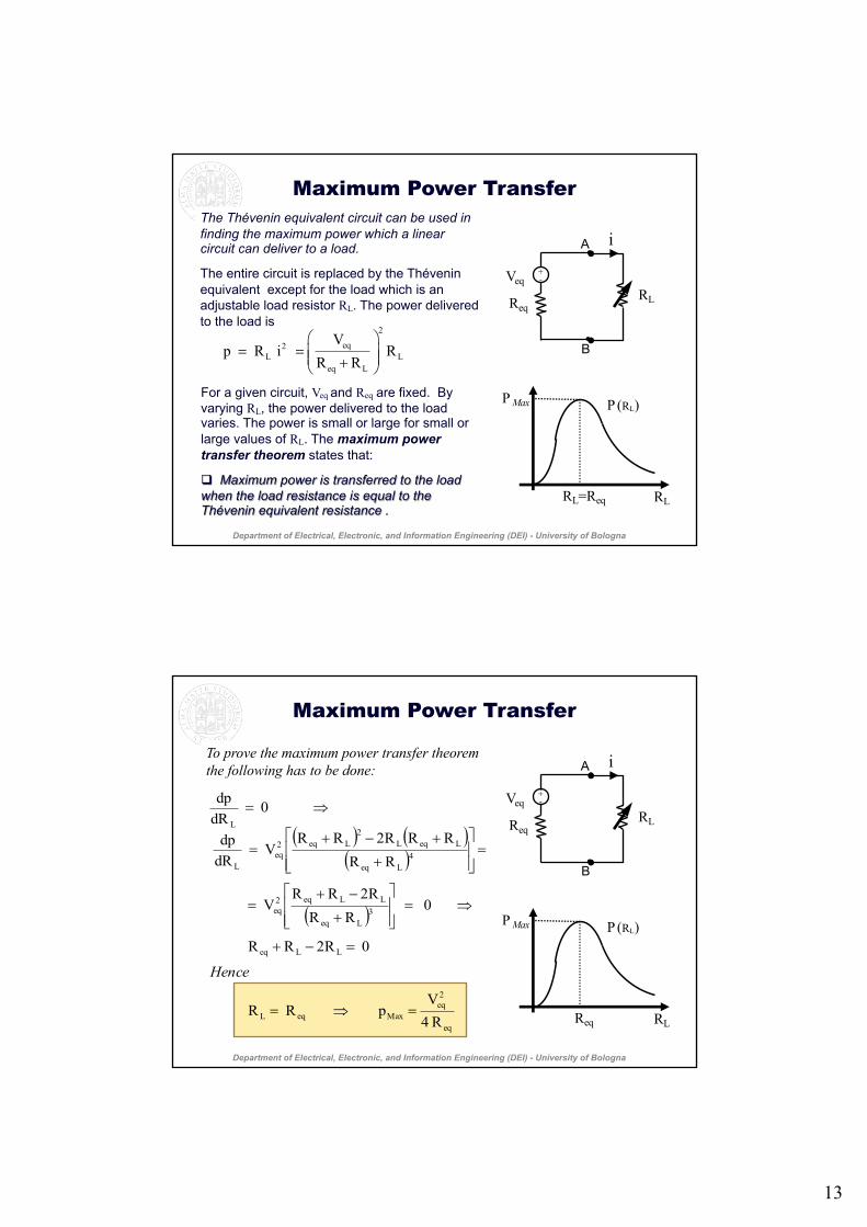
The$Thévenin equivalent$circuit$can$be$used$in$finding$the$maximum$power$which$a$linear$circuit$can$deliver$to$a$load.$
The&entire&circuit&is&replaced&by&the&Théveninequivalent&&except&for&the&load&which&is&an&adjustable&load&resistor&RL.&The&power&delivered&to&the&load&is
For&a&given&circuit,&Veq and&Req are&fixed.&&By&varying&RL,&the&power&delivered&to&the&load&varies.&The&power&is&small&or&large&for&small&or&large&values&of&RL.&The&maximum&power&transfer&theorem&states&that:
! Maximum$power$is$transferred$to$the$load$when$the$load$resistance$is$equal$to$the$Thévenin equivalent$resistance$.
2
eq2L L
eq L
Vp R i R
R R! "
= = # $# $+% &
•
•
Department&of&Electrical,&Electronic,&and&Information&Engineering&(DEI)&; University&of&Bologna
( ) ( )( )
( )
eq
2eq
MaxeqL
LLeq
3Leq
LLeq2eq
4Leq
LeqL2
Leq2eq
L
L
R 4V
p R R
0 R2RR
0 RR
R2RRV
RR
RRR2RRV
dRdp
0 dRdp
=!=
="+
!=##$
%
&&'
(
+
"+=
=##$
%
&&'
(
+
+"+=
!=
Hence
Maximum Power Transfer
Req
Veq
•
•B
A
RL
i
+-
Req
P (RL)
RL
PMax
To prove the maximum power transfer theorem the following has to be done: •
•
Department)of)Electrical,)Electronic,)and)Information)Engineering)(DEI))6 University)of)Bologna

14
Department)of)Electrical)Engineering)– University)of)Bologna27
adjustable*load*resistance
������
branch*current ����
branch*tension ����
element equation ������
equivalent*circuit ���
general*method*of*the*circuit*analysis
����(����)
input ��
load*resistance ����
maximum*power*transfer*theorem
��������
method*of*the tensionsubstitution
��������
network*function ����
nodal*analysis ����
node*voltage ����
Norton’s*theorem ����
output ��
reference*node ����
resonance*frequency ����
supernode ��
superpositionprinciple
����
Tellegen’s theorem ����
Thévenin’sequivalent*circuit
������
Terminology English – Chinese
Department)of)Electrical)Engineering)– University)of)Bologna28
Thévenin’s theorem �����
topology2equations ���
transfer2admittance ����
transfer2function ���
transfer2impedance ����
unknown ��
voltage2gain ���
Terminology English – Chinese

15
29
adjustable*load*resistance
resistenza*di*carico*variabile
branch*current corrente*di*ramo
branch*tension tensione di*ramo
element equation equazione**descrittiva*dell’elemento*circuitale
equivalent*circuit circuito*equivalente
general*method*of*the*circuit*analysis
metodo generale*di*analisi**circuitale
input ingresso
load*resistance resistenza*di*carico
maximum*power*transfer*theorem
teorema*di*massimo*trasferimento*di*potenza
method*of*the tensionsubstitution
metodo di*sostituzione*delle*tensioni
network*function funzione*di*rete
nodal*analysis analisi*nodale
node*voltage potenziale*di*nodo
Norton’s*theorem teorema*di*Norton
output uscita
reference*node nodo*di riferimento
resonance*frequency frequenza*di*risonanza
supernode supernodo
superpositionprinciple
principio*di*sovrapposizione*degli*effetti
Tellegen’s theorem teorema*di*Tellegen
Thévenin’sequivalent*circuit
circuito*equivalente*di*Thévenin
Terminology
Department)of)Electrical,)Electronic,)and)Information)Engineering)(DEI))6 University)of)Bologna
30
Terminology
Thévenin’s theorem teorema di0Thévenin
topology0equations equazioni0topologiche
transfer0admittance ammettenza0di0trasferimento
transfer0function funzione0di0trasferimento
transfer0impedance impedemza di0trasferimento0
unknown incognita
voltage0gain guadagno0di0tensione
Department)of)Electrical,)Electronic,)and)Information)Engineering)(DEI))6 University)of)Bologna