Methods and systems for preventing short message service (SMS ...
20
US 20020159387A1 (12) Patent Application Publication (10) Pub. N0.2 US 2002/0159387 A1 (19) United States Allison et al. (43) Pub. Date: Oct. 31, 2002 (54) METHODS AND SYSTEMS FOR PREVENTING SHORT MESSAGE SERVICE (SMS) MESSAGE FLOODING (76) Inventors: Rick L. Allison, Apex, NC (US); Peter J. Marsico, Carrboro, NC (US) Correspondence Address: JENKINS & WILSON, PA 3100 TOWER BLVD SUITE 1400 DURHAM, NC 27707 (US) (21) Appl. No.: 09/908,753 (22) Filed: Jul. 19, 2001 Related US. Application Data (60) Provisional application No. 60/273,442, ?led on Mar. 5, 2001. STI MSU RECEIVED BY LIM 5T2 MTP LEVEL I E- 2 PROCESSING PERFORMED 1... GWS PROCESSING PERFORMED DISCRIMINATION FCA INDICATED? Yes lNTERNALLY ROUTE TO FCM CARD Publication Classi?cation (51) Int. C1.7 ............................... .. H04J 3/14; H04J 1/16 (52) us. Cl. ....................... .. 370/229; 370/338; 370/349; 455/466; 455/566 (57) ABSTRACT A short message service (SMS) ?ood control routing node includes an SMS ?ood control module that receives short message service messages, determines the presence of short message service ?ooding, and takes appropriate action, such as discarding short message service messages that result in ?ooding. The presence of short message service message ?ooding may be determined by maintaining a count of short message service messages addressed to a particular called party Within a time period. If the count exceeds a threshold, the short message service message that caused the count to exceed the threshold may be discarded. The routing node may generate a message the originator of a short message service message ?ood and/or to an enforcement agency. EXI RACT LOOKUP KEY VALUES FROM MSU STU SEARCH FLOOD CONTROL TABLE INCREMENT SMS MESSAGE C0 UNTER l BT17 NORMALIZE > THREgHOLD ‘ $110 HMRT PROCESSING Yes 1 ST11 31,19 PASS MESSAGE D CARD SMS Messge TO OUTBOUND DCM VIA IMT BUS
Transcript of Methods and systems for preventing short message service (SMS ...

US 20020159387A1
(12) Patent Application Publication (10) Pub. N0.2 US 2002/0159387 A1 (19) United States
Allison et al. (43) Pub. Date: Oct. 31, 2002
(54) METHODS AND SYSTEMS FOR PREVENTING SHORT MESSAGE SERVICE (SMS) MESSAGE FLOODING
(76) Inventors: Rick L. Allison, Apex, NC (US); Peter J. Marsico, Carrboro, NC (US)
Correspondence Address: JENKINS & WILSON, PA 3100 TOWER BLVD SUITE 1400 DURHAM, NC 27707 (US)
(21) Appl. No.: 09/908,753
(22) Filed: Jul. 19, 2001
Related US. Application Data
(60) Provisional application No. 60/273,442, ?led on Mar. 5, 2001.
STI
MSU RECEIVED BY LIM
5T2
MTP LEVEL I E- 2 PROCESSING PERFORMED
1... GWS PROCESSING
PERFORMED
DISCRIMINATION
FCA INDICATED?
Yes
lNTERNALLY ROUTE TO FCM CARD
Publication Classi?cation
(51) Int. C1.7 ............................... .. H04J 3/14; H04J 1/16 (52) us. Cl. ....................... .. 370/229; 370/338; 370/349;
455/466; 455/566
(57) ABSTRACT
A short message service (SMS) ?ood control routing node includes an SMS ?ood control module that receives short message service messages, determines the presence of short message service ?ooding, and takes appropriate action, such as discarding short message service messages that result in ?ooding. The presence of short message service message ?ooding may be determined by maintaining a count of short message service messages addressed to a particular called party Within a time period. If the count exceeds a threshold, the short message service message that caused the count to exceed the threshold may be discarded. The routing node may generate a message the originator of a short message service message ?ood and/or to an enforcement agency.
EXI RACT LOOKUP KEY VALUES FROM MSU
STU
SEARCH FLOOD CONTROL TABLE
INCREMENT SMS MESSAGE C0 UNTER
l BT17 NORMALIZE
>
THREgHOLD ‘ $110
HMRT PROCESSING
Yes 1 ST11 31,19 PASS MESSAGE
D CARD SMS Messge TO OUTBOUND DCM VIA IMT BUS

Patent Application Publication Oct. 31, 2002 Sheet 1 0f 9 US 2002/0159387 A1
H PSwE EQ momma
M42092

Patent Application Publication Oct. 31, 2002 Sheet 2 0f 9 US 2002/0159387 A1
m Emmi E2 @025
62% =26

Patent Application Publication Oct. 31, 2002 Sheet 3 0f 9 US 2002/0159387 A1
m oSwE QM? mega
m2 mi?ooom
E25 $6 3V 2% H2 5 039% €
:25 Exam 2% AV
:25 9&5 2%
2m Esié @
MQ> Om;
ATV 2w Esié 6
Mam Umzm
MA>
2m “25% 3
A
Uwz m2

Patent Application Publication Oct. 31, 2002 Sheet 4 0f 9 US 2002/0159387 A1
08 vmm
w PSwE EQ @025 v8 N8 08 EN 28 2? <60 2:
\\ imawwmmpm zoi<ui§< @295 5802 v55 1225mm? .
E55 M63693 ZQQQEHQ 2920222200 mSz . $36
omm


Patent Application Publication Oct. 31, 2002 Sheet 6 0f 9 US 2002/0159387 A1
w Ch
7
mm 2.5 05%
mm; - OJOIWMEIP A $5 @
%
ELM
mJmE, JOE-ZOO OOO'E 1015M
@ @EwE
P5 ukm Fm
OmSE Gamma mvzammmuomm
Patent Application Publication Oct. 31, 2002 Sheet 7 0f 9 US 2002/0159387 A1
128
MSCNLR
Figure 7
MSCN LR
400 Sending MS

w oEwE
Oct. 31, 2002 Sheet 8 0f 9 US 2002/0159387 A1 Patent Application Publication
>
7 £8; 2865 ?kmw / _
/ 8w
_ 26:0 Oh / _
u ................................ 1. / 3m
0% m _ m %< L m 2% m m
N a? _ a
858mm _ __
mg ...................................... ..... .‘ §OEQOSQQ< MOHZHOO UOOHHH m M m komwqwz
“ n =2 8 o
- n @855 uownuamnlx " G05.“ Brawn‘ NE 4/
wow
/
/ 2; .EE wEw
com

Patent Application Publication Oct. 31, 2002 Sheet 9 0f 9 US 2002/0159387 A1
CD .5 .20) 82 (D u:
MSCNLR
500
MPP Figuré: 9
MSC/V LR
600

US 2002/0159387 A1
METHODS AND SYSTEMS FOR PREVENTING SHORT MESSAGE SERVICE (SMS) MESSAGE
FLOODING
RELATED APPLICATIONS
[0001] This application claims the bene?t of US. Provi sional Patent Application No. 60/273,442 ?led Mar. 5, 2001, the disclosure of Which is incorporated herein by reference in its entirety.
TECHNICAL FIELD
[0002] The present invention relates to methods and sys tems for controlling the delivery of short message service messages to a subscriber in a mobile communications net Work. More particularly, the present invention relates to methods and systems for preventing a mobile subscriber from being overWhelmed or ?ooded by the simultaneous or near simultaneous delivery of a large volume of SMS messages.
BACKGROUND ART
[0003] Short message service, Which Was ?rst introduced by European Wireless netWork operators in 1991, enables mobile subscribers to easily send and receive teXt messages via a Wireless handset. As the convergence of Wireless communication netWorks and Internet data netWorks has increased, the sending and receiving of SMS messages via computer terminals has also become commonplace. Although speci?cations and industry standards related to SMS are constantly evolving and being modi?ed, SMS messages have traditionally been used to convey readable teXt information, Where the teXt may include any combina tion of alphanumeric characters. After the initial teXt mes saging application, service providers began focusing on using SMS as a means of eliminating alphanumeric pagers by permitting tWo-Way general purpose messaging and noti?cation services. One service that has been provided using SMS is voice mail noti?cation service. As technology and netWorks continued to mature, a variety of services Were introduced, including electronic mail (email) and faX inte gration, paging integration, interactive banking, and infor mation services such as stock quotes, neWs highlights, etc.
[0004] SMS delivery service provides a mechanism for transmitting “short” messages to and from SMS-capable terminals (e.g., Wireless handsets, personal computers, etc.) via the signaling component of the Wireless communication netWork. With particular regard to the sending and receiving of SMS messages by a Wireless handset, a Wireless netWork provides the transport facilities necessary to communicate short messages betWeen a short message service center (SMSC) and a Wireless handset. A short message service center functions as a store and forWard platform for short messages. In contrast to earlier teXt message transmission services, such as alphanumeric paging, SMS technology is designed to provide guaranteed delivery of an SMS message to a destination. That is, if a temporary netWork failure prohibits the immediate delivery of an SMS message, then the short message is stored in the netWork (i.e., at the SMSC) until the destination becomes available. Another of the key and distinguishing characteristics of SMS service With respect to previously available message communication services is that an active mobile handset is able to receive or transmit a short message at any time, regardless of Whether or not a voice or data call is in progress.
Oct. 31, 2002
[0005] SMS can be characteriZed as an out-of-band packet delivery technique With loW per-message bandWidth require ments. Hence, SMS services are appealing to netWork oWners and operators. FIG. 1 is a netWork diagram illus trating an SMS implementation in a global system for mobile communication (GSM) Wireless netWork. It Will be appreciated that a functionally similar SMS architecture could also be employed in non-GSM Wireless netWorks. In any event, FIG. 1 includes a Wireless communication net Work, generally indicated by reference numeral 100. Wire less netWork 100 includes a sending mobile terminal 110 that formulates and sends SMS messages and a base station system 112 that manages the netWork-to-air interface and reliably transmits the SMS message into the core Wireless netWork. In this particular eXample, the receiving end of the netWork includes a base station system 126 and a receiving mobile terminal 128. Wireless netWork 100 also includes a pair of mobile sWitching centers (MSCs) 114 and 124, a pair of signal transfer points (STPs) 116 and 122, a short message service center 118 and a home location register (HLR) 120. SMSC 118 is responsible for relaying, storing, and forWard ing short messages betWeen sending and receiving SMS terminals. HLR 120 is a database platform used for perma nent storage and management of mobile subscriber pro?les and locations. HLR databases permanently store information about subscribers that belong to the same netWork as the HLR. A database element knoWn as a visitor location register (VLR) is used to temporarily store information about subscribers Who are currently “roaming” in the area serviced by the VLR. The VLR may belong to the subscrib er’s home netWork or to a non-home netWork. VLR data bases are typically integrated Within MSC netWork ele ments. Thus, a stand-alone VLR node is not shoWn in FIG. 1. The HLR and VLR store information needed to correctly route voice calls or data communications to a mobile sub scriber. This information may include an international mobile station identi?cation (IMSI), a mobile identi?cation number (MIN), a mobile directory number (MDN), a mobile station ISDN number (MSISDN), and the identi?cations of the VLR and MSC With Which the subscriber is currently associated.
[0006] With particular regard to short message service operations, HLR 120 provides SMSC 118 With netWork routing information for the receiving mobile subscriber or mobile terminal 128. In certain cases, HLR 120 may inform SMSC 118, Which has previously initiated unsuccessful short message delivery attempts to a speci?c mobile station, that the mobile station is noW recogniZed by the mobile netWork to be accessible.
[0007] MSC 114 is sometimes referred to as an SMS interWorking MSC (SMS-IWMSC) because it is capable of receiving a short message from a Wireless netWork and submitting it to the appropriate SMSC. In practice, SMS IWMSC nodes are typically integrated With an MSC in the netWork, but may also be integrated With the SMSC. MSC 124 is sometimes referred to as an SMS gateWay MSC (SMS-GMSC) because it is capable of receiving a short message from an SMSC, interrogating a home location register (HLR) for routing information, and subsequently delivering the short message to the “visited” MSC of the recipient mobile station.
[0008] FIG. 2 illustrates a communication netWork 150, Which is a variation of the Wireless netWork 100 described above With respect to FIG. 1. NetWork 150 includes a sending email client 152 and an email server 154, rather than sending mobile station 110 and base station 112. Email

US 2002/0159387 A1
server 154 formulates SMS messages from email messages and forwards the SMS messages to SMSC 118. As such, an email message may be generated by a Wireline computer terminal residing Within a data netWork (e.g., the Internet) and sent to a mobile terminal Within a Wireless netWork as an SMS message.
[0009] The signaling infrastructure of Wireless netWork 100 may be based on signaling system no. 7 (SS7), a telecommunications industry standard signaling protocol. SMS service uses the SS7 mobile application part (MAP), Which de?nes the methods and mechanisms of signaling communication in mobile or Wireless netWorks. The MAP protocol utiliZes the transaction capabilities application part (TCAP) component of the SS7 protocol. Both North Ameri can and international standards bodies have de?ned a MAP layer using the services of the SS7 TCAP component. The North American standard is published by the Telecommu nication Industry Association and is referred to as IS-41 MAP. The international standard is de?ned by the European Telecommunication Standards Institute and is referred to as GSM MAP.
[0010] FIG. 3 is an information How diagram illustrating the delivery of a short message to a mobile subscriber or terminal in GSM Wireless netWork. This diagram assumes the IWMSC and the GMSC node are both integrated into the SMSC node. Referring to FIG. 3, in step 1, a short message, such as a teXt message, is formulated by a sending mobile terminal and is transmitted via a signaling netWork to an MSC node. In response to receiving the short message, the MSC formulates a MAP-SEND-INFO-FOR-MO-SMS query message and transmits the message to the VLR node With Which the mobile is currently registered (step 2). The VLR responds to the query and, if the receiving mobile subscriber (MS) is registered, provides the MSISDN corre sponding to the IMSI to the MSC. Upon receiving the MS information, the MSC transmits the short message in a MAP-MO-FORWARD-SHORT-MESSAGE message to the SMSC (step 3). The SMSC sends a MAP-SEND-ROUT ING-INFO message to the HLR of the SMS recipient using the recipient’s MSISDN (step 4). The HLR responds With the IMSI of the recipient and the MSC With Which it is currently registered. If the information indicates that the recipient is available (i.e. currently registered With an MSC and turned on With suf?cient memory), the SMSC then transmits the short message to the MSC in a MAP-MT FORWARD-SHORT-MESSAGE (step 5), and transmits a delivery report to the sending MSC (step 6). It Will be appreciated that an SMSC attempts to deliver a short mes sage to a receiving MS Whenever the MS is registered and available (i.e. turned on With sufficient memory), even When the MS is engaged in a voice or data call. Such service is referred to as point-to-point delivery service and is accom plished via the use of the Short Message Delivery-Point-to Point (SMD-PP) and ForWardShortMessage mechanisms in IS-41 and GSM, respectively.
[0011] In step 7, the MSC queries the VLR With Which the recipient is currently registered With a MAP-SEND-INFO FOR-MT-SMS message. The VLR returns location infor mation associated With the receiving mobile subscriber (e.g., the MSISDN number associated With the receiving mobile subscriber). Using the information obtained from the VLR database, paging and authentication operations are initiated betWeen the MS and the base station. Once the receiving MS
Oct. 31, 2002
has been authenticated and located, the MSC transmits the short message to the mobile (step 8). In step 9, information associated With the disposition or status of the SMS delivery attempt is returned to the SMSC.
[0012] It Will be appreciated that such delivery status information may be used by the SMSC to ensure or guar antee the delivery of a particular message. That is, When a short message delivery attempt by the SMSC fails due to a temporary netWork failure, the SMSC may request that it be noti?ed by the HLR When the indicated mobile subscriber becomes accessible. Such “message Waiting” functionality is achieved using the SMS noti?cation indicator in IS-41 and set message Waiting data in GSM.
[0013] From the discussion of SMS operation fundamen tals presented above, it Will be appreciated that the SMS components of a Wireless communication netWork Will diligently attempt to deliver every SMS message received by the netWork. While such guaranteed delivery service is an attractive feature for legitimate mobile subscribers, the guar anteed delivery service may also cause a mobile subscriber’s handset or terminal to be ?ooded messages in a manner that signi?cantly inconveniences the subscriber or potentially even temporarily disables the subscriber’s communication terminal. Furthermore, from a netWork operations perspec tive, SMS ?ooding incidents could have a signi?cantly negative impact on overall netWork performance. Such SMS message ?ooding could be eXecuted With malicious intent, or could simply be the unintentional result of a commercial advertising campaign. Accordingly, there eXists a long-felt need for novel methods and systems for preventing an SMSC and/or a mobile subscriber from experiencing a mass delivery or ?ooding of SMS messages.
DISCLOSURE OF THE INVENTION
[0014] According to one aspect, the present invention includes a signaling message routing node for transmitting and receiving short message service (SMS) data packets via a communications netWork. The routing node includes an SMS ?ood control database that contains information Which is used to determine Whether a receiving or called party is being ?ooded With SMS messages. The information stored in the ?ood control database may be indicative of the average rate at Which SMS messages are being sent or delivered to a mobile subscriber. In the event that the average delivery rate value exceeds a predetermined maXi mum or threshold value, SMS message delivery service to the called party is temporarily suspended. Subsequent SMS messages received at the routing node of the present inven tion that are addressed to the suspended called party may be discarded.
[0015] An SMS ?ood control application associated With the routing node may generate a neW SMS message addressed to the sending or calling party associated With a discarded message. This neW SMS message noti?es the sending or calling party that delivery of the discarded SMS message Was unsuccessful. The SMS ?ood control applica tion of the present invention may also eXamine sending party, calling party, and/or routing information contained in an SMS message received during a ?ooding episode to determine the origin of a ?ooding attack. As such, it may be possible for an SMS ?ood control application of the present invention to identify the particular netWork, netWork ele

US 2002/0159387 A1
ments, or communication terminal(s) from Which an SMS ?ooding attack is being staged. If the origin of the ?ooding attack can be determined, a neW SMS message can be generated for notifying one or more netWork operators of the incident so that appropriate steps can be taken to mitigate or terminate the attack.
[0016] Accordingly, it is an object of the present invention to prevent a short message service subscriber from being ?ooded With a large number of SMS messages in a short period of time.
[0017] It is another object of the present invention to prevent a short message service center from being ?ooded With a large number of SMS messages in a short period of time.
[0018] It is another object of the present invention to provide a netWork routing node that facilitates the enforce ment of SMS message ?ood prevention measures;
[0019] It is another object of the present invention to identify the sending or calling party responsible for an SMS message ?ooding incident.
[0020] It is another object of the present invention to notify the sending or calling party of an SMS message associated With an SMS message ?ooding incident that the offending SMS message(s) have been discarded.
[0021] It is another object of the present invention to notify a netWork operator of the occurrence of an SMS message ?ooding incident so that steps may be taken by the operator to mitigate or terminate the incident.
[0022] Some of the objects of the invention having been stated hereinabove, other objects Will be evident as the description proceeds, When taken in connection With the accompanying draWings as best described hereinbeloW.
BRIEF DESCRIPTION OF THE DRAWINGS
[0023] A description of the present invention Will noW proceed With reference to the accompanying draWings of Which:
[0024] FIG. 1 is a netWork diagram illustrating conven tional netWork elements associated With handling SMS messages originating from a mobile terminal;
[0025] FIG. 2 is a netWork diagram illustrating conven tional netWork elements associated With handling SMS message originating from an email client;
[0026] FIG. 3 is a message ?oW diagram illustrating MAP protocol messages associated With the sending and receiving of an SMS message;
[0027] FIG. 4 is block diagram of a signaling gateWay routing node suitable for use With embodiments of the present invention;
[0028] FIG. 5 is a schematic diagram of a signaling gateWay routing node including an SMS ?ood control mod ule (FCM) according to an embodiment of the present invention; [0029] FIG. 6 is a ?oW chart illustrating the processing of an SMS message by a routing node including an SMS ?ood control module according to an embodiment of the present invention;
Oct. 31, 2002
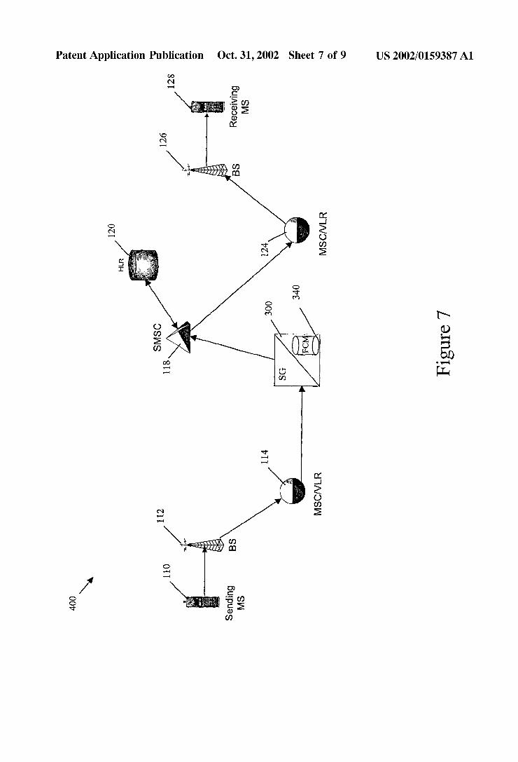
[0030] FIG. 7 is a netWork diagram illustrating a commu nications netWork including a routing node having an SMS ?ood control module according to an embodiment of the present invention;
[0031] FIG. 8 is a block diagram illustrating a stand-alone SMS message processing platform (MPP) including an SMS ?ood control module according to an embodiment of the present invention; and
[0032] FIG. 9 is a netWork diagram illustrating a commu nication netWork including a stand-alone SMS MPP accord ing to an embodiment of the present invention.
DETAILED DESCRIPTION OF THE INVENTION
[0033] Disclosed herein are several embodiments of the present invention, some of Which may include an underlying hardWare platform that performs functions similar to that of a traditional telecommunications netWork packet routing sWitch, such as a signaling gateWay (SG) routing node. Each of the integrated routing node embodiments described beloW, includes an underlying hardWare platform similar to that of high performance signal transfer point (STP) and SG products marketed by Tekelec of Calabasas, Calif., the EAGLE® STP and IP7 SECURE GATEWAYTM, respec tively. FIG. 4 is a block diagram of a signal transfer point or signaling gateWay platform suitable for use With embodi ments of the present invention. In FIG. 4, a routing node 250 includes the folloWing subsystems: a maintenance and administration subsystem (MAS) 252, a communication subsystem 254 and an application subsystem 256. MAS 252 provides maintenance communications, initial program load, peripheral services, alarm processing and system disks. Communication subsystem 254 includes an interprocessor message transport (IMT) bus that is the main communica tion bus among all subsystems in the routing node 250. The IMT bus may include tWo 125 Mbps counter-rotating serial rings.
[0034] Application subsystem 256 includes application cards or printed circuit boards capable of communicating With the other cards through the IMT bus. Numerous types of application cards can be incorporated into 250, including: a link interface module (LIM) 258 that provides SS7 links and X25 links, a data communication module (DCM) 260 that provides an Internet Protocol (IP) interface using trans mission control protocol (TCP) or other transport layer protocol, and an translation services module (TSM) 262 that provides global title translation, gateWay screening and other services. A database services module (DSM) 264 may also be provided to support triggered local number portabil ity service, as Well as advanced database services, such as the SMS ?ood control application described herein.
Integrated SMS Flood Control Routing Node Architecture
[0035] FIG. 5 illustrates a signaling gateWay 300 includ ing an internal SMS ?ood control module according to an embodiment of the present invention. In the illustrated embodiment, SG 300 includes an interprocessor message transport bus 304 that is the main communication bus among all internal subsystems Within SG 300. A pair of mainte nance and administration subsystem processors 306, an SS7-capable link Interface module 308, an IP-capable data

US 2002/0159387 A1
communication module 330, and an SMS ?ood control module (FCM) 340 are connected to IMT bus 304. These modules maybe physically connected to the IMT bus 304 such that signaling and other types of messages may be routed internally betWeen all active cards or modules. For simplicity of illustration, only single LIM, DCM, and FCM cards are shoWn in FIG. 5. HoWever, it should be appreci ated that the distributed, multi-processor architecture of SG node 300 facilitates the deployment of multiple LIM, DCM, FCM and other cards, all of Which can be simultaneously connected to and communicating via IMT bus 304.
[0036] MASP pair 306 provide maintenance communica tions, initial program load, peripheral services, alarm pro cessing and system disks. As the MASP pair are not par ticularly relevant to a discussion of SMS ?ood control application functionality, a detailed discussion of their design and operation is not provided herein.
[0037] Focusing noW on LIM card functionality, in the illustrated embodiment, LIM 308 is comprised of a number of sub-components including an SS7 MTP level 1 and 2 process 310, an I/ O buffer or queue 312, a gateWay screening (GWS) process 314, an SS7 discrimination process 316, and a distribution process 318. MTP level 1 and 2 process 310 provides the facilities necessary to send and receive digital data over a particular physical medium. MTP level 1 and 2 process 310 also provides error detection, error correction, and sequenced delivery of SS7 message packets. I/O queue 312 provides for temporary buffering of incoming and outgoing signaling message packets. GWS process 314 may examine a received message packet and determine Whether the message is to be alloWed into the sWitch for processing and/or routing. Discrimination process 316 performs a dis crimination function to determine Whether an incoming SS7 message packet requires internal processing or is simply to be through sWitched, i.e., routed to another node. In one embodiment, discrimination process 316 examines a service indicator octet (SIO) value in the received message packet in order to determine Whether internal SCCP-type processing is required. Distribution process 318 handles the internal dis tribution of SS7 message packets that require additional processing prior to ?nal routing.
[0038] DCM 330, as shoWn in FIG. 5, includes an SS7/1P converter 332 and I/O queue 334. SS7/1P converter 332 converts betWeen SS7 and IP protocol stacks to alloW transport of SS7 messages over an IP netWork. Exemplary protocols that may be implemented by SS7/1P converter 332 include TALI (as described in IETF RFC 3094) over TCP/IP and SCTP (as described in IETF RFC 2960) over IP. I/O queue 334 stores messages to be processed by higher layers. It Will be appreciated that the message packets received and transmitted by a DCM card may include transport adapter layer interface (TALI) protocol messages, session initiation protocol (SIP), M2UA, M3UA, SUA, SCTP, H.323 or other signaling protocols that may be transported via TCP/IP or similar IP-based protocols.
[0039] In general, an SMS ?ood control module (FCM) includes applications and databases that may be used to perform SMS ?ood control. FCM 340 shoWn in FIG. 5 includes a signaling connection control part sub-module 342, Which further includes a subsystem controller knoWn as a signaling connection routing controller (SCRC) 344. Responsibilities of the SCRC 344 include directing an incoming SS7 message packet to an SMS message ?ood control (MFC) application 346 and creating a neW message packet in response to information returned by MFC appli
Oct. 31, 2002
cation 346. This ability to create a neW message in response to information returned from SMS ?ood control application 346 is a signi?cant aspect of the present invention. SS7 message packets leaving SCRC 344 are received and further processed by routing process 350. Routing process 350 is responsible for the external routing of SS7 message packets that have been processed by SMS MFC application 346 and/or do not require additional processing by the SG node 300. That is, routing process 350 determines to Which LIM or DCM card an SS7 message packet should be routed for subsequent outbound transmission from the SG node. It Will also be appreciated from FIG. 5 that in one embodiment, FCM 340 is coupled to and serviced by an external provi sioning application platform (EPAP) subsystem 352 via an Ethernet connection. EPAP subsystem 352 is responsible for administration and maintenance of at least some of the SMS ?oW control data resident on FCM 340.
SMS Flood Control Module Architecture
[0040] As discussed above, a signi?cant problem associ ated With currently offered SMS services involves an SMS recipient’s inability to control the ?oW of SMS messages to his or her communication terminal. This shortcoming has the potential of becoming greatly ampli?ed as the generation of SMS message traffic outside of the traditional PSTN net Work environment continues to increase. As such, it Will be appreciated that one of the primary objectives of a routing node including an SMS ?ood control module according to an embodiment of the present invention is to provide a method by Which a netWork operator can quickly and easily control the rate at Which SMS messages are delivered to an SMS service subscriber. A netWork operator may also pro vide an individual SMS subscriber With the ability to directly control the rates at Which SMS type messages are delivered to their communication terminal by granting the SMS subscriber access to the FCA data.
[0041] In FIG. 5, FCM 340 may receive an SMS message that has been internally routed, via IMT bus 304, from a communication module such as a LIM or DCM. FCM 340 includes one or more data tables stored in memory that contain the information for implementing the SMS message ?ood control functionality described above. Table 1 shoWn beloW illustrates a simpli?ed table structure including exem plary information usable by FCM 340 in performing SMS ?ood control according to an embodiment of the present invention.
TABLE 1
Flood Control Data
KEYS) DATA
CgPA CdPA OPC DPC CID SMS# Threshold
9 1 94605500 * * * * 2 75
9194691300 * * * * 12 75
* 9194690000 * * * 1 5
* * 1 - 1- 1 * * 23 1 24
* * * 2-2-2 221 66 250
[0042] The ?ood control table structure depicted in Table 1 is presented primarily for the purposes of illustration and that practical implementation of a ?ood control application of the present invention may involve a more complex data structure, such as a tree structure. Such complex data

US 2002/0159387 A1
structures could be necessary depending upon the particular performance requirements of a given netWork implementa tion.
[0043] In any event, the sample data table structure shoWn in Table 1 contains a number of key or index ?elds includ ing: a sending or calling party identi?cation ?eld, a receiving or called party identi?cation ?eld, an originating point code (OPC) ?eld, a destination point code (DPC) ?eld, and a carrier identi?cation (CID) ?eld. In a signaling system 7 signaling environment, SMS ?ood control data that may be stored in the sending or calling party identi?er ?eld may include a calling party address (CgPA) parameter, a mobile station integrated services digital netWork number, an inter national mobile station identi?er number, or a mobile iden ti?cation number. In a SIP environment, the sending or calling party ?eld may store a SIP identi?er, such as a SIP URL.
[0044] The data stored in the sending or calling party ?eld may be used to identify the source of SMS messages that ?ood a particular netWork or mobile subscriber. For example, SMS ?ood control module 340 may maintain a count of SMS messages received Within a particular time period from a particular message originator. The message originator may be an individual or a netWork, depending on the content of the sending party identi?cation ?eld. If the count exceeds a threshold, SMS ?ood control module 340 may notify the sender and/or an enforcement agency.
[0045] The receiving or called party identi?er ?eld may store called party address (CdPA) parameters, IMSIs, MSIS DNs, or SIP identi?ers associated With receiving mobile stations. The data stored in the called party ?eld may be used to prevent SMS message ?ooding of a particular mobile station. For example, SMS ?ood control module 340 may maintain a count of SMS messages received by a particular mobile station. If the count exceeds a predetermined thresh old Within a predetermined time period, SMS ?ood control module 340 may discard SMS messages to the terminal being ?ooded. [0046] The OPC ?eld may store point codes associated With SMS message originators. For example, if it is knoWn that a particular netWork frequently causes SMS ?ooding, the point code of a sWitch in that netWork may be provi sioned in Table 1 to monitor and control ?ooding originating from a node in that netWork. In the event that an SMS ?ood control application of the present invention is implemented or practiced in a non-SS7 communication netWork, the data stored in OPC ?eld Would correspond to a netWork address, such as an IP address, that is valid in the netWork Within Which the invention is being practiced.
[0047] The DPC ?eld in Table 1 may store point code values of recipient nodes in a netWork that are subject to SMS message ?ooding. For example, the DPC ?eld may store the point code of an SMSC in a particular netWork to prevent SMS message ?ooding of the SMC. Once again, if an SMS ?ood control application of the present invention is implemented in a non-SS7 communication netWork, the data stored in DPC ?eld Would correspond to a netWork address, such as an IP address, that is valid in the netWork Within Which the invention is being practiced. Finally, carrier ID (CID) ?eld may be used to determine Whether a carrier identi?ed in the carrier ID ?eld of an SMS ?ood control message has an SMS ?ood control agreement With the oWner of routing node 300.
Oct. 31, 2002
[0048] In addition to the screening or key ?elds, each entry or record in Table 1 contains an SMS message counter ?eld and an SMS message delivery rate threshold ?eld. The SMS message counter ?eld stores information related to the number of SMS messages received and processed by SG node 300 for each particular entry. FCM 340 may include a timer used in conjunction With the value stored in the message counter ?eld to calculate the rate of SMS message delivery. For example, in one embodiment FCM 340 may periodically Zero the values in the SMS counter ?elds upon expiration of the timer. In such an embodiment, the values stored in the threshold ?eld may be set to the maximum alloWable number of SMS messages for the speci?ed time period. In an alternate embodiment, FCM 340 may calculate the average or instantaneous delivery rate of SMS messages for each entry. In this embodiment, the value stored in the threshold ?eld may be indicative of the maximum instanta neous or average rate.
[0049] The sending party, receiving party, OPC, and DPC ?elds in Table 1 may be provisioned manually by a netWork operator or an end user. HoWever, in addition to or instead of such manual provisioning, these ?elds may be provi sioned automatically by ?ood control module 340. For example, When ?ood control module 340 receives an SMS message, ?ood control module 340 may perform a lookup in the ?ood control table based on data extracted from the message. If ?ood control module 340 fails to locate a matching entry, ?ood control module may automatically add an entry to the ?ood control table using the parameters from the received message. The next time a message is received having the same parameters, ?ood control module 340 Will locate the previously created entry and increment the mes sage count. The threshold ?eld for automatically-created entries may be set to a default value determined by the netWork operator. In this manner, FCM 340 automatically provisions itself to monitor neW sources of SMS message ?ooding.
[0050] According to another aspect of the invention, FCM 340 may include a provisioning interface 353 that alloWs a user or a netWork operator to provision values in the ?ood control table. Provisioning interface 353 may be any type of interface that alloWs a user or netWork operator to provision or alter ?ood control data in the SMS ?ood control table. Examples of such interfaces may include text-based inter faces, graphical interfaces, or interfaces that include a com bination of text and graphics. Interface 353 may be accessed using any suitable means, such as FTP or HTTP via the Internet.
[0051] Using a table-driven architecture to perform SMS ?ood control greatly facilitates provisioning and updating of SMS ?ood control data. A netWork operator can increase alloWable thresholds of SMS messages in a netWork as equipment is upgraded Without reWriting and re-compiling ?ood control softWare. Similarly, an end user can increase SMS ?ood control thresholds as mobile terminal processing and storage capacity improves. The combination of a pro visioning interface With a table-driven ?ood control archi tecture alloWs both end users and netWork operators to easily control the ?oW of SMS messages.
[0052] The ?ood control table data structure and data presented in Table 1 are merely illustrative of the basic information necessary to provide the required SMS ?ood

US 2002/0159387 A1
control functionality. In practice, the actual record structures and overall database design may vary according to particular implementation and system performance requirements.
SMS Flood Control Module Operation
[0053] FIG. 6 is a ?oW chart illustrating exemplary steps performed by a routing node including an SMS ?ood control module in processing SMS messages according to an embodiment of the present invention. For purposes of illus tration, it is assumed that the SMS message being processed is an SS7 transaction capabilities application part (TCAP) or mobile application part-based SMS message. HoWever, an SMS ?ood control module of the present invention may be used in a non-SS7 environment to process SMS messages that utiliZe non-SS7 signaling protocols (e.g., SIP, SUA/ SCTP, H.323, TALI, etc.). In any event, the block diagram presented in FIG. 5 may be used in conjunction With the processing ?oW chart of FIG. 6 to better understand the operation of a routing node including an SMS ?ood control module according to an embodiment of the present inven tion. The dashed line in FIG. 5 illustrates the path that an SMS message may folloW through the routing node.
[0054] Beginning at inbound LIM 308, an SS7-based SMS signaling message is received (ST1), and SS7 MTP Level 1 and 2 processing is performed on the incoming signaling message packet by the MTP Level 1 and 2 process 310, as indicated by step ST2. When MTP Level 1 and 2 processing is complete, the signaling message packet is temporarily buffered in 1/0 queue 312 before being passed up the stack to GWS process 314, Where various parameters in message are examined to determine Whether the message is to be alloWed into the sWitch (ST3). Such gateWay screening parameters may include originating point code, destination point code, and carrier ID.
[0055] Once the message successfully passes GWS pro cessing, the message is directed to discrimination process 316, as indicated in step ST4. Discrimination process 316 examines the SMS signaling message packet and determines Whether the packet requires further processing by SG node 300. In one embodiment, discrimination process 316 may examine destination point code and service indicator octet parameters contained Within the message transfer part header of an SS7 signaling message packet. In the event that a signaling message includes a DPC value corresponding to the SS7 netWork address of SG node 300 and an SIO value corresponding to that of an SCCP message, the message is identi?ed as potentially requiring SMS ?ood control pro cessing. In the example shoWn in FIG. 5, it is assumed that discrimination process 316 examines the DPC and SIO values associated With the received SMS signaling message and subsequently determines that ?ood control processing of the message packet may be required (ST5). If discrimination process 316 determines that a received message does not require SMS ?ood control processing, the message may be routed from SG node 300 via a communication module such as a LIM or DCM (ST6). In the event that SMS ?ood control processing may be required, the SMS message is passed to distribution process 318. Distribution process 318 may internally distribute the SMS message from the receiving LIM 308 to the FCM 340 via IMT bus 304, as indicated in step ST7.
[0056] In step ST8, the SMS signaling message arrives at FCM 340 and SCCP process 342 receives the packet. Within SCCP process 342, the message packet is passed to the SCRC controller 344. In step ST9, SCRC controller 344
Oct. 31, 2002
decodes and examines packet content information contained Within the SMS signaling message header in order to verify that the message is an SMS message. In one embodiment, such a determination is made through examination of a subsystem (SSN) parameter that is contained in the SCCP portion of an SMS message. While different netWorks may de?ne and recogniZe different SSN values to represent MAP type messages (SMS is a MAP message), an SSN value typically used by Wireless netWork operators to indicate a MAP type message is SSN=5. In another embodiment, the SMS message identi?cation function may be performed by examining the operation code in the MAP portion of the SMS message. The operation code may indicate that the message is a ForWardShortMessage message, Which is used in GSM netWorks to deliver short messages. Hence, it may be particularly important that FCM 340 identify these types of messages for ?ood control purposes. The operation code parameter can be used to select ForWardShortMessage mes sages for processing. Other messages may be routed nor mally. [0057] In the event that a message is determined to be of a type other than SMS, the message may be passed to routing process 350 for routing from SG node 300, as indicated by steps ST10, ST11, and ST12. HoWever, if a message is determined to be an SMS message, data used to perform SMS ?ood control processing is next extracted from the message (ST13). In the exemplary implementation described herein, such data may include a CgPA parameter, a CdPAparameter, an OPC parameter, a DPC parameter, and a CID parameter, all of Which correspond to key ?elds in the sample ?ood control table (Table 1) that resides on or is accessible by FCM 340. It should be noted that the MAP MSISDN, IMSI or MIN may be used, although they are not shoWn in the example table. As such, some or all of the data extracted from the SMS message is used to search the ?ood control table for a matching entry or record (ST14 and ST15). If a matching record or entry is not located, the message is passed to routing process 350 for routing from SG node 300, as indicated by steps ST10, ST11 and ST12. As discussed above, if a matching entry is not located, a neW entry may be created for the received message. In the event a matching entry is located in the ?ood control table, the data contained in the matching entry is used to perform SMS ?ood control processing.
[0058] In one embodiment, SMS ?ood control processing may include incrementing the value of the SMS message counter ?eld associated With the matching entry (ST16). The incremented SMS message counter ?eld value may then be compared to the threshold ?eld value to determine Whether to route or discard the SMS message. It Will be appreciated that depending upon the particular implementation, addi tional calculations may need to be performed to ensure that the SMS message counter value and corresponding thresh old value are similarly de?ned. That is, if a user has speci?ed a threshold of ten SMS messages per minute and the period of the reset timer is anything other than one minute, then the tWo ?eld values must be normaliZed before a meaningful comparison can be made (ST17 and ST18).
[0059] As indicated above, the data stored in Table 1 may be used by FCM 340 to control SMS ?ooding in a variety of Ways. For example, if a calling party address in a received SMS message matches a value in a calling party identi?er ?eld, FCM 340 may determine Whether the number of SMS

US 2002/0159387 A1
messages received from the particular calling party exceeds the threshold speci?ed in the threshold ?eld. If the number exceeds the threshold, the calling party may be noti?ed and further messages from the particular calling party may be blocked. Such sender-based ?ood control may be performed for netWorks or for individual subscribers. In order to perform netWork-Wide sender-based ?ood control, FCM 340 may keep a count of all messages received from a particular netWork. In order to perform sender-based ?ood control on an individual basis FCM 340 may maintain a count of SMS messages from a particular calling party. Either type of sender-based ?ood control is intended to be Within the scope of the invention.
[0060] Yet another type of ?ood control that may be performed by FCM 340 includes recipient-based ?ood con trol. Recipient-based ?ood control may be performed on an individual basis or on a netWork basis. In order to perform recipient-based ?ood control on an individual basis, FCM 340 may maintain a count of SMS messages directed to a particular called party Within a predetermined time period. In order to perform recipient-based ?ood control on a netWork basis, FCM 340 may maintain a count of SMS messages received by a particular netWork Within a prede termined time period. Either type of recipient-based ?ood control is intended to be Within the scope of the invention.
[0061] In yet another alternative embodiment, FCM 340 may combine sender and receiver data in received message to perform ?ood control based on the sender and the intended recipient. This combined type of ?ood control may be performed on an individual basis or on a netWork basis by provisioning the appropriate values in Table 1. Thus, FCM 340 according to the present invention is capable of per forming sender-based, receiver-based, or sender and receiver-based SMS ?ood control by provisioning the appro priate values in Table 1.
[0062] Returning to FIG. 6, if the SMS message delivery rate does not exceed the threshold value, the message is passed to routing process 350 for routing from SG node 300, as indicated by steps ST10, ST11 and ST12. HoWever, if it is determined that the SMS message delivery rate exceeds the threshold value, the SMS message may be discarded (ST19). [0063] As stated above, SMS ?ood control module 340 may generate a neW message in response to determining that the SMS message delivery rate exceeds the threshold value. Such a neW message may be an SMS message that is addressed to the calling or sending party associated With the discarded SMS message. This neW SMS message may inform the calling or sending party that the original SMS message Was not delivered to the intended recipient and that additional SMS messages should not be sent to the intended recipient for a predetermined timeout period. In addition to or instead of a neW message directed to the calling or sending party of the discarded SMS message, a neW message may be created to alert a netWork operator to the SMS message ?ooding incident. Such a netWork management message may include information that can be used to identify the origin of an SMS message ?ooding attack (e.g., CgPA, OPC, CID, etc.) and, as such, may assist a netWork operator in mitigating or terminating an SMS ?ooding incident.
[0064] FIG. 7 illustrates an exemplary Wireless commu nication netWork 400 including a signaling gateWay With an SMS ?ood control module according to an embodiment of
Oct. 31, 2002
the present invevention. In FIG. 7, Network 400 is similar in architecture to communication netWork 100 illustrated in FIG. 1. HoWever, instead of STP pair 116 and 122 illustrated in FIG. 1, communication netWork 400 includes SG node 300 including SMS ?ood control module 340. As such, a mobile subscriber 110 may originate an SMS message destined for another mobile subscriber 128. The SMS mes sage, addressed to MS 128, is received into the Wireless netWork via base station system 112 and is subsequently routed to MSC 114. MSC 114 in turn routes the message to signaling gateWay 300. The SMS message is received by signaling gateWay 300 and is processed in a manner similar to that described above With respect to FIGS. 5 and 6. In the event that the SMS ?ood control application Within signal ing gateWay 300 determines that MS 128 is being ?ooded With SMS messages, the SMS message is discarded and is consequently not delivered to the intended destination. Given the particular netWork architecture illustrated in this example, the discarding of the SMS message prevents ?ooding at tWo critical locations in the netWork. That is, an SMSC typically serves as an intermediate store and forWard buffer element for SMS messages in an SMS capable netWork. Consequently, all SMS messages destined for MS 128 Would ?rst be received, processed, and temporarily buffered by SMSC 118. Since SMS messages that are identi?ed as causing ?ooding are discarded at SG 300, both the intermediate SMSC 118 and the intended recipient MS 128 are shielded from large volumes of SMS message traf?c that Would be associated With a ?ooding incident. Such “downstream” SMS traf?c shielding is one of the key bene?cial attributes of the present invention.
Stand-alone SMS Flood Control Module Architecture
[0065] Yet another embodiment of the present invention involves the implementation of an SMS ?ood control mod ule on a stand-alone SMS message processing platform that is not located Within a routing node. A functional block diagram of one embodiment of such a message processing platform is shoWn in FIG. 8. In FIG. 8, SMS MPP 500 includes SS7 and IP protocol stacks 502 and an I/O queue 504. SS7 and IP protocol stacks 502 may be capable of sending and receiving SS7 messages, IP messages, and IP-encapsulated SS7 messages. I/O queue 504 buffers mes sages Waiting to be processed by higher and loWer layers. SMS MPP 500 further includes an application selection manager 506 and an application library 508. In this simpli ?ed example, application library 508 includes several mes sage processing applications that are adapted to receive and subsequently process a variety of signaling messages, including an SMS ?ood control application 510. SMS mes sage ?ood control application 510 may include a provision ing interface 512 that alloWs a user to provision or changes SMS message ?ood control data. Provisioning interface 512 may be similar in structure and operation to provisioning interface 353 described above With respect to FIG. 5. Hence, a description thereof Will not be repeated herein.
[0066] Application selection manager 506 may select an application for processing a received message based on parameters extracted from the message. Table 2 shoWn beloW illustrates exemplary parameters that may be used to select the appropriate application.

US 2002/0159387 A1
TABLE 2
Application Selection Data
KEY(s)
Type OPC SLS DPC CID APPLICATION
* 1-1-1 * * SMS ?ood control
IAM * * * 7 App2
IAM * * 4-4-4 * App3
[0067] From Table 2, parameters that can be used to select the appropriate application include the message type, OPC, DPC, SLS, and carrier ID. These parameters may be used alone or in combination to select the appropriate application.
[0068] Ausage measurements and billing (UMB) database 520 maintains usage metrics and billing information related to the screening and processing of SMS messages by SMS MPP 500. In one embodiment, UMB 52010 maintains information associated with screened messages in the form of call detail records (CDRs). Table 3 shown below illus trates exemplary CDR data that may be stored in UMB database 520.
TABLE 3
Usage Measurements and Billing Information
KEY BII I ING RECORD DATA
Appli Date Time cation CdPA CgPA Carrier
Dec. 01, 13:01:24 Flood- 9194691300 9194671100 221 2000 Con
Dec. 01, 13:01:24 Flood- 9193457012 9194621450 636 2000 Con
Dec. 01, 13:01:24 App2 9193457894 914671230 221 2000
[0069] Each CDR is represented by a row in Table 3. Each CDR includes date, time, and application key ?elds. Each CDR also includes a called party (CdPA) or receiving party identi?er ?eld that contains the phone number or identi?er (e.g., email address, URL, etc.) associated with the SMS receiving party, a calling party (CgPA) or sending party identi?er ?eld that contains the phone number or identi?er (e.g., email address, URL, etc.) associated with the SMS sending party, and a carrier ID ?eld that contains the carrier ID associated with an SMS message. UMB database 520 may also collect and maintain peg count type usage mea surements and statistics associated with screened or pro cessed SMS messages.
Stand-alone SMS Flood Control Module Operation
[0070] Focusing now on operation of a message process ing platform (MPP) embodiment of the present invention, the path of a typical SS7 SMS signaling message requiring SMS ?ood control processing is traced through a sample communication network 600 shown in FIG. 9. Again, the sample network 600 is similar in architecture to the com munication network 100 illustrated in FIG. 1. However, unlike network 100, communication network 600 includes the stand-alone SMS message processing platform (MPP) 500 for providing SMS ?ood control processing service.
Oct. 31, 2002
[0071] A mobile subscriber 110 may originate an SMS message that is destined for another mobile subscriber 128. The SMS message, addressed to MS 128, is received into the wireless network via base station system 112 and is subse quently routed to MSC 114. In this particular example, MSC 114 routes the message to the signal transfer point 116. If the SMS message is addressed to an SS7 point code associated with the STP 116, the SMS message is received by STP 116, which performs a global title translation (GTT) or other functionally similar re-directing routing address translation operation. Those skilled in the art of SS7 communications will appreciate that GT is a translation process used to determine the location (e.g., SS7 point code and subsystem) of a message processing platform (e. g., MPP, service control point, database node, etc.). Such GTT functionality is well known and widely deployed in modern communication networks. In any event, as a result of the GTT or GTT-like processing, the SMS message is routed from STP 116 to MPP 500 for SMS ?ood control processing. At this point, it should be noted that it is also possible that an SMS message could be directly addressed to MPP node 500, in which case no GTT or GTT-like processing would be required by STP 116. In such a scenario, the MPP node 500 would perform the necessary SMS ?ood control processing as well as any GTT or GTT-like processing required to route the message to SMSC 118.
[0072] In the particular example discussed with regard to FIGS. 8 and 9, SMS MPP 500 receives an SMS message packet via an SS7 or IP communication link from STP 116. SS7/1P protocol stacks 502 receive the SS7 message signal ing unit (MSU) and remove any headers not required by higher layers. The SMS message is then passed via I/O queue 504 to application selection manager 506. As dis cussed previously, ASM 506 may examine a number of message parameters and/or message characteristics for the purpose of determining the particular message processing application or applications that are required. Table 2 shown above includes a number of index or key ?elds by which the table may be searched to determine the particular application that is required to service the received message. These ?elds may be used alone or in combination as a search or lookup key.
[0073] In the example presented in FIG. 9, it is assumed that the originating point code (OPC) address information contained in the received SMS message is 1-1-1. Referring to the sample application selector data shown in Table 2, an OPC value of 1-1-1 indicates the need for SMS ?ood control processing. As such, the SMS message is passed from ASM 506 to SMS ?ood control application (FCA) 510. FCA processing then proceeds in a manner similar to the FCA processing described above with regard to the FIG. 5.
[0074] In the event that the SMS ?ood control application residing on SMS MPP node 500 determines that MS 128 is being ?ooded with SMS messages, the SMS message is discarded and is consequently not delivered to the intended destination. Once again, in such a case, discarding of the SMS message prevents ?ooding at two critical locations in the network. That is, typically an SMSC serves as an intermediate store and forward buffer element for SMS messages in an SMS capable network. Consequently, all SMS messages destined for MS 128 would ?rst be received, processed, and temporarily buffered by SMSC 118. Since ?ood related SMS messages are discarded at SG 300, both intermediate SMSC 118 and intended recipient MS 128 are shielded from large volumes of SMS message traffic that would be associated with a ?ooding incident. Once again, it

US 2002/0159387 A1
Will be appreciated that such “downstream” SMS traf?c shielding is one of the key bene?cial attributes of the present invention. It Will be understood that various details of the invention may be changed Without departing from the scope of the invention. Furthermore, the foregoing description is for the purpose of illustration only, and not for the purpose of limitation—the invention being de?ned by the claims.
What is claimed is: 1. A method for preventing short message service (SMS)
message ?ooding, the method comprising:
(a) receiving a ?rst SMS message including called and calling party identi?cation information;
(b) performing a lookup in a message ?ood control (MFC) database using at least one of the called and calling party identi?cation information;
(c) in response to locating a matching entry in the MFC database, using information contained in the matching entry to detect the presence of SMS message ?ooding; and
(d) in response to detecting the presence of SMS message ?ooding, discarding the ?rst SMS message.
2. The method of claim 1 Wherein receiving a ?rst SMS signaling message includes receiving a signaling system 7 (SS7) mobile application part (MAP)-based SMS message.
3. The method of claim 2 Wherein receiving an SS7 MAP-based SMS message includes receiving an Internet protocol (IP)-encapsulated SS7 MAP-based SMS message.
4. The method of claim 1 Wherein receiving a ?rst SMS message includes receiving a session initiation protocol (SIP)-based SMS message.
5. The method of claim 1 Wherein the called party identi?cation information includes a mobile subscriber inte grated services digital netWork (MSISDN) number.
6. The method of claim 1 Wherein the called party identi?cation information includes an international mobile station identi?er (IMSI).
7. The method of claim 1 Wherein the called party information includes an email address.
8. The method of claim 1 Wherein the called party information includes an Internet protocol (IP) address.
9. The method of claim 1 including, in response to detecting the presence of SMS message ?ooding, generating a second SMS message addressed to the calling party associated With the ?rst SMS message.
10. The method of claim 9 Wherein the second SMS message noti?es the calling party that the ?rst SMS message Was not delivered to the called party.
11. The method of claim 1 including, in response to detecting the presence of SMS message ?ooding, generating a second SMS message addressed to a third party.
12. The method of claim 11 Wherein the second SMS message noti?es the third party of an originator of a ?ood of SMS messages.
13. The method of claim 11 Wherein the third party is a government agency.
14. The method of claim 11 Wherein the third party is a netWork operator.
15. The method of claim 1 Wherein using information in the matching entry to detect the presence of SMS message ?ooding includes determining Whether the number of SMS messages received by a called party Within a predetermined time period exceeds a threshold number of SMS messages.
Oct. 31, 2002
16. The method of claim 1 Wherein using information in the matching entry to detect the presence of SMS message ?ooding includes determining Whether the number of SMS messages received from a calling party Within a predeter mined time period exceeds a threshold number of SMS messages.
17. The method of claim 1 Wherein using information in the matching entry to detect the presence of SMS message ?ooding includes determining Whether the number of SMS messages received by a netWork Within a predetermined time period exceeds a threshold number of SMS messages.
18. The method of claim 1 Wherein using information in the matching entry to detect the presence of SMS message ?ooding includes determining Whether the number of SMS messages received from a netWork Within a predetermined time period exceeds a threshold number of SMS messages.
19. The method of claim 1 Wherein receiving a ?rst SMS message includes receiving the ?rst SMS message at a netWork routing node and redirecting the ?rst SMS message to a message processing platform separate from the netWork routing node.
20. The method of claim 19 Wherein redirecting the ?rst SMS message includes examining a destination address contained in the ?rst SMS message.
21. The method of claim 20 Wherein the destination address contained in the ?rst SMS message includes an SS7 destination point code (DPC) value.
22. The method of claim 20 Wherein the destination address contained in the ?rst SMS message includes an IP address value.
23. The method of claim 19 Wherein redirecting the ?rst SMS message includes redirecting the ?rst SMS message based on a message type indicator included Within the message.
24. The method of claim 23 Wherein the message type indicator includes a subsystem number (SSN) identi?er.
25. The method of claim 23 Wherein the message type indicator includes a SIP message type identi?er.
26. The method of claim 19 Wherein redirecting the ?rst SMS message includes examining an origination address contained in the ?rst SMS message.
27. The method of claim 26 Wherein the origination address contained in the ?rst SMS message includes an SS7 originating point code (OPC) value.
28. The method of claim 26 Wherein the origination address contained in the ?rst SMS message includes an IP address value.
29. The method of claim 1 comprising, in response to locating a matching entry in the MFC database, increment ing an SMS message counter associated With the matching entry.
30. The method of claim 1 comprising, in response to failing to locate a matching entry in the MFC database, inserting a neW entry in the MFC database.
31. A method for collecting information that can be used to prevent a calling party Who has previously ?ooded a called party With SMS messages from ?ooding another subscriber or the netWork again, the method comprising:
(a) at a netWork element, detecting that a calling party identi?ed in a received SMS message is ?ooding a called party With SMS messages and, in response, entering information for identifying the calling party in a message ?ood control (MFC) database;

US 2002/0159387 A1
(b) in response to detecting that the calling party is ?ooding the called party, checking the MFC database to determine Whether the calling party has previously ?ooded any subscriber identi?ed in the MFC database; and
(c) in response to locating a matching entry in the MFC database, sending a message to a third party indicating that the calling party is a repeat offender.
32. The method of claim 31 Wherein the third party is a netWork administrator With the capability to remove the offending party’s authentication from the network, thereby preventing further access.
33. The method of claim 31 Wherein the third party is a netWork administrator With the capability to enable screen ing of calls to block the offending party from accessing the netWork.
34. The method of claim 31 Wherein the third party is a government agency.
35. An SMS ?ood control routing node comprising:
(a) a ?rst communication module for receiving SMS messages from a netWork;
(b) an SMS message ?ood control (MFC) database for storing information for preventing SMS message ?ood ing; and
(c) an SMS ?ood control module for receiving the SMS messages from the ?rst communication module for performing a lookup in the SMS MFC database based on information extracted from the SMS messages and detecting the presence of SMS message ?ooding.
36. The SMS ?ood control routing node of claim 35 Wherein the ?rst communication module is a signaling system 7 (SS7)-capable link interface module (LIM).
Oct. 31, 2002
37. The SMS ?ood control routing node of claim 35 Wherein the ?rst communication module is a Internet pro tocol (IP)-capable data communication module (DCM).
38. The SMS ?ood control routing node of claim 35 Wherein the SMS ?ood control information includes the number of SMS messages received Within a predetermined time period.
39. The SMS ?ood control routing node of claim 35 Wherein the SMS ?ood control information includes the number of SMS messages received by a particular mobile subscriber Within a predetermined time period.
40. The SMS ?ood control routing node of claim 35 Wherein the SMS ?ood control information includes the number of SMS messages received from a particular calling party Within a predetermined time period.
41. The SMS ?ood control routing node of claim 35 Wherein the SMS ?ood control information includes the number of SMS messages received from a particular net Work Within a predetermined time period.
42. The SMS ?ood control routing node of claim 35 Wherein the SMS ?ood control information includes the number of SMS messages directed to a particular netWork element Within a time period.
43. The SMS ?ood control routing node of claim 35 Wherein the SMS ?ood control module is located Within the SMS ?ood control routing node.
44. The SMS ?ood control routing node of claim 35 Wherein the SMS ?ood control module is located external to the SMS ?ood control routing node.
45. The SMS ?ood control routing node of claim 35 comprising a provisioning interface for alloWing a user to add or modify the data in the SMS ?ood control database.
* * * * *