Methodology for a Safety Case of a Dual Purpose Cask … · Spent nuclear fuel which is generated...
116
Methodology for a Safety Case of a Dual Purpose Cask for Storage and Transport of Spent Fuel Report of WASSC/TRANSSC joint working group 2011-2013
Transcript of Methodology for a Safety Case of a Dual Purpose Cask … · Spent nuclear fuel which is generated...
Methodology for a Safety Case of
a Dual Purpose Cask for Storage and
Transport of Spent Fuel
Report of WASSC/TRANSSC joint working group 2011-2013


FOREWORD
Spent nuclear fuel which is generated in the operation of nuclear reactors needs to be safely
managed following its removal from the reactor core. Reactor storage pools were designed on the
assumption that after a short period of time spent nuclear fuel would be removed for
reprocessing, disposal or storage elsewhere. Owing to delays in making decisions on the
disposition of spent fuel and in putting decisions into effect, the volume of highly radioactive
spent fuel that needs to be stored is growing, and additional storage capacity is required.
One of the widely used options for additional storage capacity is the use of dry spent fuel storage
casks. From various existing dry storage concepts, several member states are utilizing a concept
of dual purpose casks (DPCs).The concept of storing spent fuel in a container that can be safely
handled and stored whilst providing levels of radiation shielding, heat dissipation, criticality
safety and containment that are acceptable for transport in the public domain has obvious
benefits, but it should be understood that these benefits do come with inherent risks. These
inherent strategic risks need to be managed over the storage timescale.
In April 2011, the IAEA initiated a Working Group to develop guidance for Member States for
an integrated safety case for DPCs for the transport and storage of spent fuel, with the support of
both the Transport Safety Standards Committee (TRANSSC) and the Waste Safety Standards
Committee (WASSC) with the intention of developing guidance for the structure and content of
an integrated safety case for a DPC.
This TECDOC is published based on the discussion during the three year activity by the Working
Group addressing the technical aspects of demonstrating the safety of the DPC design during
storage and compliance with the transport safety requirements extant at the time of transport at
the end of storage period. The IAEA highly appreciates the contributions from various experts to
this TECDOC. The IAEA officers responsible for this publication were Y. Kumano and S.
Whittingham of the Division of Radiation, Transport and Waste Safety.

CONTENTS
INTRODUCTION .................................................................................................................................................. 1
1. Background ........................................................................................................................... 1
2. Working group activities ...................................................................................................... 2
3. Objective and scope .............................................................................................................. 2
4. Definitions ............................................................................................................................. 4
5. Structure of this publication ................................................................................................. 4
PART 1: GENERAL PRINCIPLES AND TECHNICAL INFORMATION ............................................................. 6
1.1 Document control of DPCSC ............................................................................................... 6
1.2 Administrative information .................................................................................................. 6
1.3 Specification of contents ...................................................................................................... 7
1.4 Specification of the DPC ...................................................................................................... 8
1.5 Storage and transport conditions .......................................................................................... 9
1.5.1 Basic concept ................................................................................................................. 9
1.5.2 Operational scenarios .................................................................................................. 11 1.5.3 Operational scenarios impact ..................................................................................... 18
1.6 General design considerations and acceptance criteria .................................................... 25
1.6.1 Relationship between regulatory requirements, performance criteria, acceptance
criteria, design criteria, and design specification ..................................................................... 25 1.6.2 Basic design prerequisites........................................................................................... 28
1.6.3 Performance criteria .................................................................................................... 29 1.6.4 Design principles and acceptance criteria.................................................................. 30
1.7 Ageing considerations ........................................................................................................ 38
1.7.1 Introduction ................................................................................................................. 38
1.7.2 Components and ageing mechanisms to be considered ............................................ 39 1.7.3 Component evaluation ................................................................................................ 43
1.7.4 Preshipment inspection after storage period .............................................................. 49 1.8 Compliance with regulatory requirements ........................................................................ 52
1.8.1 Transport package design approval and storage licensing period ............................ 52 1.8.2 License types for storage ............................................................................................ 53
1.9 Operation ............................................................................................................................. 53
1.10 Maintenance plan ................................................................................................................ 54
1.11 Emergency plan................................................................................................................... 54
1.12 Management systems .......................................................................................................... 54
1.12.1 Lessons learned from literature on ageing management .......................................... 55 1.12.2 Essence of the systematic approach to ageing management .................................... 57
1.12.3 Ageing management programme for DPC storage facilities .................................... 59 1.12.4 DPCSC periodic review .............................................................................................. 61
1.12.5 Record management .................................................................................................... 61 1.13 Decommissioning ............................................................................................................... 62

PART 2: SPECIFIC TECHNICAL ASSESSMENT .............................................................................................. 63
2.1 Common provisions for all technical analyses in part 2 of the safety case ..................... 63
2.1.1 Bases for technical assessment ................................................................................... 63 2.1.2 Description and justification of analysis methods .................................................... 63
2.1.3 Analysis of DPC design .............................................................................................. 64 2.1.4 Comparison of acceptance criteria with results of analysis ...................................... 64
2.2 Structural Analyses ............................................................................................................. 65
2.2.1 Reference to DPC design for structural analysis ....................................................... 65
2.2.2 Assumptions for structural analysis ........................................................................... 65 2.2.3 Description and validation of methods for structural analysis ................................. 65
2.2.4 Structural assessment .................................................................................................. 67 2.3 Thermal analyses ................................................................................................................ 69
2.3.1 Reference to DPC design for thermal analysis .......................................................... 69 2.3.2 Assumptions for thermal analysis .............................................................................. 69
2.3.3 Description and validation of methods for thermal analysis .................................... 69 2.3.4 Thermal assessment .................................................................................................... 71
2.4 Activity release analysis ..................................................................................................... 72
2.4.1 Reference to DPC design for activity release analysis ............................................. 72
2.4.2 Assumptions for activity release analysis .................................................................. 72 2.4.3 Description and validation of calculation method for activity release analysis ...... 74
2.4.4 Activity release calculations ....................................................................................... 74 2.5 External dose rates analysis................................................................................................ 81
2.5.1 Reference to DPC design for dose rates analysis ...................................................... 81 2.5.2 Assumptions for dose rates analysis .......................................................................... 81
2.5.3 Description and validation of calculation method for dose rates analysis............... 82 2.5.4 Dose rate calculations ................................................................................................. 82
2.6 Criticality safety analysis ................................................................................................... 83
2.6.1 Reference to DPC design for criticality safety analysis ........................................... 83
2.6.2 Assumptions for criticality safety analysis ................................................................ 84 2.6.3 Description and validation of the calculation method for criticality safety
analysis 85 2.6.4 Criticality safety calculations ..................................................................................... 85
REFERENCES ..................................................................................................................................................... 88
DEFINITIONS ..................................................................................................................................................... 94
ABBREVIATIONS .............................................................................................................................................. 98
ANNEX: EXAMPLE FOR THE HOLISTIC APPROACH OF A DPCSC FOR AN OPERATIONAL
SCENARIO ........................................................................................................................................................ 100
CONTRIBUTORS TO DRAFTING AND REVIEW ........................................................................................... 106

1
INTRODUCTION
This introduction provides the background and history of the Working Group activities as well as
general discussion to consider for subsequent parts of this report (PART 1 and PART 2).
1. BACKGROUND
Operating nuclear reactors generate spent fuel, which needs to be safely managed following its
removal from reactor cores. The reactor pool capacities were designed based on the assumption
that fuel would be removed after a certain period of time either for reprocessing, disposal, or
further storage. However, as a result of storing higher burn-up fuel, significantly increased
timeframe till disposal solutions are prepared, and delays in decisions on strategies for spent fuel
management, the volume of spent fuel discharged from reactors which needs to be managed and
stored is on the increase. Consequently, additional storage capacity may be needed following the
initial storage in reactor pools.
In some countries, a concept of dual purpose cask (DPC) is considered as an option for further
storage. This is because of that the concept increases flexibility for storage capacity, as well as its
economic efficiency that can reduce the complexity of handling highly radioactive spent fuels.
The primary safety objectives of a DPC design relate to national storage regulations and
compliance with the transport regulations extant at the time of transport. DPCs are generally
designed with a dual containment boundary and are designed and maintained so the primary lid
need not be opened for inspection or maintenance during storage or before transport after storage
to avoid unnecessary degradation, incidental risks, and radiological exposures. Storage based on
this concept does not require additional equipment (such as hot cells).
If a DPC is designed based on a single-containment boundary concept, it is necessary to provide
appropriate maintenance facilities that can be used to maintain the cask in the event of failure of
primary containment boundary.
Managing spent fuel using a DPC involves storage and on-site and off-site transport of the spent
fuel before and after storage. Many countries require licenses for storage of the spent fuel in the
DPC or for storage facilities containing DPC packages. Most countries also require package
design approval for the DPC package to be transported.
Safety assessment and approval or licensing procedures have to consider the differences between
the two DPC configurations (i.e. the DPC transport package design and the DPC storage package
design). A DPC provided for transport is usually equipped with impact limiters and often has an
one-lid closure system. The acceptance criteria for this DPC transport package are defined in
IAEA transport regulations SSR-6 [1]. The DPC transport package also needs to be designed so
that it can be used in an operational mode that is different from usual transport packages. More
specifically, the DPC transport package needs to be transported after several decades of storage
and, therefore, needs to use long term resistant packaging components that require ageing
considerations.

2
A DPC package provided for storage is usually not equipped with transport impact limiters, but
often has a closure system with additional lids, including lid interspace pressure monitoring. The
acceptance criteria for this DPC storage package are specific for the regulations for on-site
activities, including storage and on-site transport, and they are very often different from SSR-6
requirements. Nevertheless, most of the safety relevant DPC components are the same for both
purposes.
Therefore, demonstration of compliance of the DPC package with national and international
transport regulations, as well as with the storage requirements in an integrated manner is
recommended.
2. WORKING GROUP ACTIVITIES
The International Conference on Management of Spent Fuel from Nuclear Power Reactors,
which was hosted by the IAEA in June 2010, recommended establishing a joint international
working group to provide guidance to Member States for integrating the safety cases for storage
and transport of spent fuel in a DPC in a holistic manner. A consultancy meeting (CS-130) was
convened to “Establish a Working Group on an Integrated Safety Demonstration for the Dual Use
Cask for Spent Nuclear Fuel” at the IAEA in November 2010. The meeting also developed the
terms of reference for that working group.
The objectives of the working group were:
(1) To prepare an IAEA guidance document (TECDOC or Safety Report) containing guidance
for the structure and contents of a DPC integrated safety case (DPCSC) (as a supporting
document to GSR Part 5 [2]; GSG-3 [3]; SSG-15 [4]; and SSG-26) [5];
(2) To provide recommendations to the Transport Safety Standards Committee (TRANSSC),
Waste Safety Standards Committee (WASSC), Radiation Safety Standards Committee
(RASSC), and Nuclear Safety Standards Committee (NUSSC), as appropriate, for changes
to be made to existing IAEA requirements and guidance relevant to the licensing and use of
transport and storage casks for spent fuel.
Plenary meeting for the working group meetings were held at the IAEA Headquarters in April
2011 (TM-40975), April 2012 (TM-42920), and April 2013 (TM-44985).
The working group took the technical guide on package design safety reports for the transport of
radioactive material [6] as an initial model regarding structuring of the guidance. The work was
distributed into 4 sub-groups.
3. OBJECTIVE AND SCOPE
This TECDOC contains guidelines for the structure and contents of a DPCSC. The scope is only
for dual-purpose metal storage and transport casks for short and long term dry storage (as defined
in SSG-15, Appendix I [4]). This publication does not cover requirements for a safety case of a
DPC storage facility. A canister is considered a DPC component when it is contained within a
DPC as a part of its internals.

3
This TECDOC aims to assist designers, vendors, operators, applicants, licensees, regulators,
technical support organizations, and others in developing and reviewing the safety case and
supporting safety assessment. This TECDOC contains guidance that can be used, irrespective of
how the safety case and safety assessment process is addressed within individual national
regulatory frameworks.
IAEA Safety Standards Series, GSR, Part 5 [2] (see also Ref. [7]) introduces the concept of
safety case as follows:
The safety case is a collection of arguments and evidence in support of the safety
of a facility or activity. The safety case will normally include the findings of a
safety assessment, and will typically include information (including supporting
evidence and reasoning) on the robustness and reliability of the safety assessment
and the assumptions made therein.
An integrated safety case for transport and storage aims to support the application for the package
design approval for transport and the application for the licensing of the storage cask (as part of
the safety case for the storage facility). The DPCSC may be a collection of scientific and
technical arguments including safety assessments in support of:
(1) The demonstration of compliance with IAEA transport regulations SSR-6 [1] for off-site
transport, including transport after storage;
(2) The demonstration of compliance with the international standards and national
requirements for dry storage of spent fuel as they apply to the DPC package during its
storage period.
This TECDOC is based on the concept of an integrated DPCSC. This concept assumes that the
DPCSC is in line with the IAEA recommendations on the safety case for predisposal
management of radioactive waste [4] and linked to the transport and storage approvals as
described in subsequent paragraphs (see also Figure 1).
The basic information for the DPCSC is the description of the DPC and its contents, the impact
conditions and acceptance criteria. The term ‘impact conditions’ means all basic data for the
safety assessment arising from normal, off-normal, and accident conditions of storage and
routine, normal, and accident conditions of transport (RCT, NCT, and ACT). Transport
regulations provide impact conditions for off-site transport. The impact conditions for storage
need to be specified based on national regulations and an assessment of the operational
conditions at the storage facility. ‘Acceptance criteria’ are based on regulatory limits that the
DPC package and the storage facility are required to meet (e.g. dose rates). The acceptance
criteria for off-site transport are given in the transport regulations. The acceptance criteria for
storage (to be applied to each DPC package/storage facility combination) need to be specified
based on national regulations and an assessment of the operational conditions of the storage
facility. This basic information is complemented by instructions for operation and maintenance.
The DPCSC needs then to demonstrate that a DPC of the specified design loaded with the
specified contents and being exposed to the defined impact conditions, operations, and
maintenance meets the specified acceptance criteria. A regulatory body could assess this
demonstration leading to an approval of the DPC package design. Assuming approval will be

4
given only if compliance with the transport regulations has been demonstrated in the DPCSC, the
design can be approved as a transport package. Regarding storage, the DPCSC could qualify the
DPC package for storage in a specific facility.
This concept leaves some freedom to the DPC designer in defining impact conditions and
acceptance criteria. In either case, the transport requirements are not so flexible and need to be
met. An incorrect choice of storage impact conditions or acceptance criteria could lead to
problems in obtaining a licence for the storage facility, if the DPC package as defined in the
DPCSC does not meet the regulatory requirements and operational limits of the storage facility.
Therefore, impact conditions and acceptance criteria have to be selected based on a careful
review of the regulatory requirements and operational limits and conditions of the storage facility.
Of course, acceptance criteria can also be set in a more restrictive manner, which should provide
some additional margin in assessing current and future storage facilities.
4. DEFINITIONS
The definitions included in IAEA Safety Glossary [7] and IAEA transport regulations SSR-6 [1]
apply throughout this publication. The definitions section toward the end of this publication
provides additional publication-specific definitions.
5. STRUCTURE OF THIS PUBLICATION
Part 1 provides a generic consideration of the organization and contents of a DPCSC. It also
provides information on administrative matters; specification of contents; DPC specifications,
DPC performance criteria; and compliance with regulatory requirements, operation, maintenance,
and management systems as a part of the DPCSC.
Part 2 provides generic and specific considerations for technical assessments of the safety case.
Figure 1 shows the structure of the DPCSC.
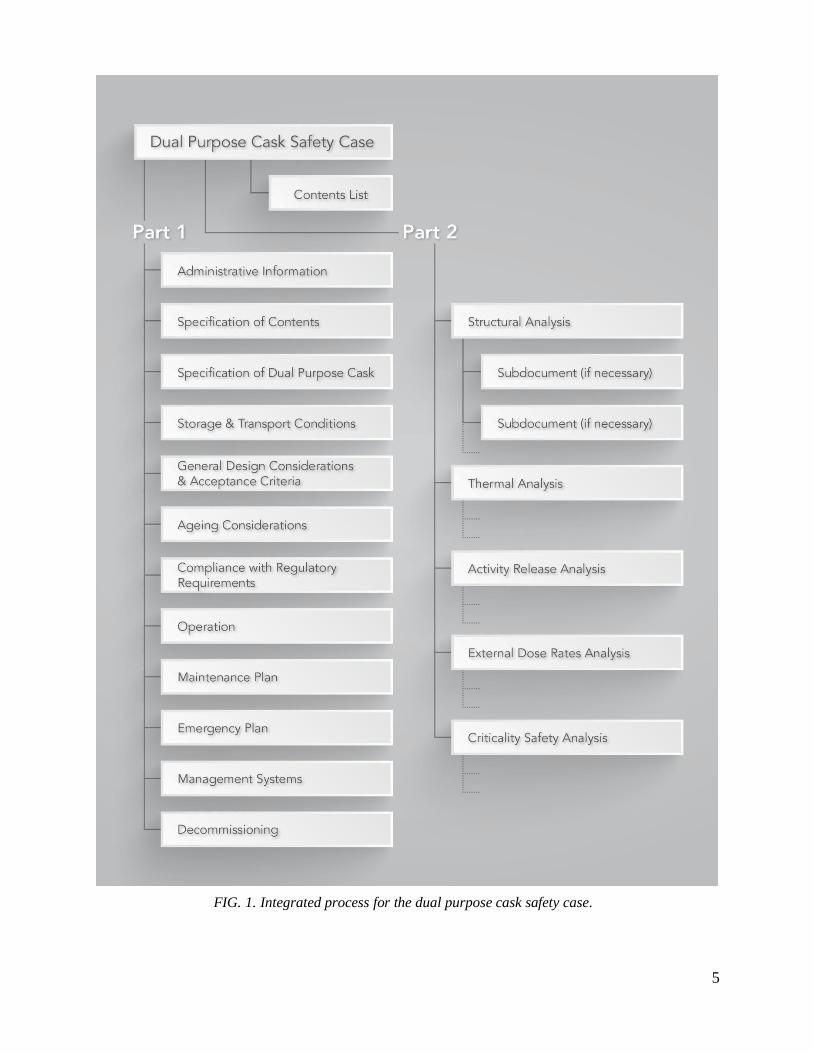
5
FIG. 1. Integrated process for the dual purpose cask safety case.

6
PART 1: GENERAL PRINCIPLES AND TECHNICAL INFORMATION
Part 1 of the DPCSC needs to include the following information.
1.1 TRACKING THE HISTORY OF DPCSC
As soon as a DPC has its own life cycle starting from design and ending with decommissioning, a
DPCSC is a ‘rolling process’ and is updated periodically, or when incorporating new findings.
Therefore it is important to clearly identify exact stage of the life cycle and the issue version of
each DPCSC document or subdocument and keep updated a list of DPCSC documents, including
a description of each document version.
1.2 BASIC ADMINISTRATIVE AND TECHNICAL INFORMATION
The DPCSC include the following basic administrative and technical information:
(1) Designer-specific model identification of the DPC.
(2) Identification of DPC designer (name, address, contact details).
(3) Type of transport package.
(4) Transport-specific limitations of operational conditions after short or long term storage,
e.g.:
(a) Modes of transport for which approval is requested;
(b) Any special instructions to the carrier such as required special transport
configurations (e.g. transport frame, canopy).
(5) Storage specific limitations of operational conditions for generic DPC package licenses,
e.g.:
(a) Need for storage building;
(b) Environmental conditions (temperature, wind, snow, etc.);
(c) Storage orientation (vertical, horizontal);
(d) Handling capacity (weight, dimensional limits);
(e) Fuel retrievability (hot cell, etc.);
(f) Maintenance/repair capability;
(g) Inspection and maintenance frequency;
(h) Storage pitch (minimum distance between DPC packages);

7
(i) Accident conditions (drop height/orientation, tip over, tornado, missile, flooding.
etc.);
(j) Siting requirements, including seismic, tsunami, and volcano;
(k) Monitoring requirements.
(6) Reference to applicable transport regulations and/or storage requirements, including the
edition of IAEA Regulations for the Safe Transport of Radioactive Material and other
relevant IAEA Safety Standards to which the DPC design refers.
(7) List of laws, regulations, guidelines, codes, standards, and licenses applicable to the design,
fabrication, quality assurance programme, transport, and storage of the DPC package based
on the defined operational scenarios, as well as the related nuclear facilities and modes of
transport to be used. From these laws, regulations, and guidelines, the regulatory
requirements (technical, operational, and other) that control the design, analysis, and
operation of the DPC package need to be determined and included in the DPCSC. These
regulatory requirements have to be tabulated and presented in Section 1.8 with a
description of the design, safety analysis results, and references to DPCSC sections.
(8) Reproducible conceptual drawings need to be provided. The conceptual drawings may
include bird’s eye views and three dimensional illustrations showing the configuration of
the DPC in each transport and storage modes indicating the major components of the DPC,
such as packaging, impact limiters, devices for thermal insulation, and packaging inserts, if
applicable. The illustrations need to indicate at least the overall outside dimensions, the
masses of the main components of the packaging, and the gross mass for empty and loaded
conditions.
1.3 SPECIFICATION OF CONTENTS
A detailed description of the permitted radioactive contents of the DPC needs to include, but is
not limited to, the following information, as applicable:
(1) Radionuclides / radionuclide composition; progeny, if applicable.
(2) Activity, mass and concentrations, and heterogeneities, if applicable.
3) Physical and chemical state, geometric shape, arrangement, loading restrictions, irradiation
parameters, moisture content, and material specifications (particularly, information on
spent fuel degradation during storage).
(4) Fuel condition (e.g. damaged, non-damaged, intact, or consolidated fuel rods; fuel
assemblies with missing rods,). Fuel integrity may be defined in the national regulations or
guidelines (e.g. Interim Staff Guidance 1 by US-NRC [Ref. 8]) or based on international
technical reports (e.g. IAEA Nuclear Energy Series NF-T-3.6 Ref. [9]).
(5) Nature and characteristics of the radiation emitters.
(6) Thresholds of heat generation rate for contents.
8
(7) Mass of fissile material or fissile nuclides.
(8) Other contents such as canisters and non-fuel hardware (e.g. control rods, sources, thimble
plugs, burnable poison rods, moisture absorbers, etc.).
(9) Typical parameters of spent fuel which provide the basis for the derivation of some of
above descriptions, such as fuel design type, initial enrichment, burnup and cooling period.
(10) The acceptable parameters of the history of the spent fuel before loading. Before it is
loaded in the DPC, the fuel will have been subjected to a number of processes, including
irradiation in the reactor, handling operations and pool storage, all of which can influence
the physical integrity of the fuel rods and the structural components. The history of the
spent fuel before loading is, therefore, an important input into the safety case.
1.4 SPECIFICATION OF THE DPC
The DPC design has to be defined by including the following information, as applicable:
(1) A list of all DPC components, monitoring systems, and complete design drawings for
transport and storage configurations;
(2) A parts list of all safety related components including bolts and seals;
(3) Material specifications of all DPC components and standard items and methods of their
manufacture including requirements for material procurement, welding, other special
processes, non-destructive evaluation, and testing;
(4) Information on material degradation during storage and transport;
(5) A description of:
(a) The DPC body, lid (closure mechanism) and inserts;
(b) The DPC components of the containment system;
(c) The DPC components required for shielding;
(d) The DPC components for criticality control;
(e) The DPC components for thermal protection;
(f) The DPC components for heat dissipation;
(g) The protection against corrosion;
(h) The protection against contamination;
(i) The transport configuration, including any devices required for the transport
including impact-limiting components, canopies and tie-downs, which may have an
effect on the safety of the package;

9
(j) The storage configuration, including any devices required for the safe handling and
storage that may have an effect on the safety of the package in storage operations.
1.5 STORAGE AND TRANSPORT CONDITIONS
This section needs to describe the performance criteria that allow the DPC design to meet
applicable transport regulations and the storage safety requirements such as summarized here:
(1) Radioactive material containment;
(2) Shielding (control of external radiation levels);
(3) Criticality prevention;
(4) Heat removal (prevention of damage caused by heat);
(5) Stored spent fuel retrievability;
(6) Structural integrity;
(7) Ageing.
For this purpose, the DPC designer has to first consider DPC package operational scenarios, and
has to identify the regulatory and licensing requirements. The designer has to then develop
operational procedures for each operational step included in the scenarios, and identify conditions
to which the DPC package could be subjected considering the operational limits. Furthermore,
the designer needs to describe analysis assumptions and data used for the safety case and how
they are derived from the design and the behaviour of the package under routine, normal, and
accident conditions of transport (RCT, NCT, and ACT) and normal, off-normal and accident
conditions of storage. This is especially true regarding the release of radioactive material,
radiation levels, criticality safety, heat removal, structural integrity of the DPC, and integrity of
contained spent fuel.
This section needs to include items to be considered in developing the DPCSC, from the
determining the operational scenario to interpreting the safety analysis basis.
1.5.1 Basic concept
When developing the DPCSC, the DPC designer first determines the DPC package operational
scenarios by considering:
(1) Operational scenarios
The DPC designer has to consider DPC package operational scenarios, including those in the
DPCSC, together with the nuclear facilities (either actual or postulated) related to each scenario.
The DPC designer also needs to justify each operational scenario (e.g. country specific
requirements, regulatory situation, siting, technical feasibility, safety philosophy) selection in the
DPCSC.

10
(2) Safety case for DPC package storage system
A complete safety case for the DPC package storage system will be achieved by integrating the
DPCSC and related nuclear facilities safety cases. Thus, the DPC designer and nuclear facility
operator responsibilities need to be agreed upon before developing the safety case. Therefore:
(a) In general, safety cases related to DPC package operations in a given nuclear facility
have to be included in the nuclear facility safety case, as the safety analysis or
assessment and the associated acceptance criteria depend on the environmental
conditions unique to that facility.
(b) In some cases, normal operations (e.g. loading, unloading and handling of DPC
packages) and off-normal operations (e.g. operations during loss of power, loss of
crane operation) in nuclear facilities are specific to the DPC design. In such cases, the
safety cases related to the operations involving the DPC package at the storage
facility may also be included in the DPCSC.
(c) Nuclear facilities accidents, except those incidents that are considered and for which
acceptance criteria are defined, are to be considered by the nuclear facilities.
(3) Environmental conditions
Some Member States provide a regulatory framework of regulations or guidelines that stipulates
environmental conditions to be considered at the storage facility for the DPC package storage
design. This allows approval of the DPC package design independently of the storage site.
Storage facility operators may select a DPC design that fits their site conditions from approved
designs or design a storage facility to meet selected DPC design specifications. In the latter case,
the DPCSC can include the safety assessment of the DPC package in the specified storage
environment.
(4) Time spans
The DPC designer has to consider the intended storage and transport time span.
(5) Operational procedures and environmental conditions of operation.
The DPC designer has to develop procedures for each step in the considered operational
scenarios and include them in the DPCSC. At the same time, environmental conditions of the
DPC package operations have to be clearly defined and included in the DPCSC. The developed
operational procedures have to be presented in Section 1.9, “Operation” in the DPCSC.
(6) Retrievability
Retrievability of the DPC content is required under GSR Part 5, requirement 11 [2] and
specifically addressed in SSG-15, paras 6.133 and 6.134 [4].
In this publication, retrievability is the ability to recover DPC contents. Some states may define
the condition at retrieval.

11
(7) Retrieval Facility
The storage safety may not rely as heavily on the previous operational steps if a retrieval facility
has the necessary infrastructure to enable opening a DPC for inspection of the internals and the
spent fuel in the DPC. The same is true if the storage facility allows for the opening of the lid for
DPC maintenance and repair work.
Inspection of spent fuel and DPC internals demonstrates the storage safety at the storage facility
and ensures the safety of transport after storage and safety of spent fuel retrieval at the next
destination facility.
1.5.2 Operational scenarios
1.5.2.1 Operational steps that constitute the operational scenario
The DPC operational scenario consists of various steps addressed in the DPCSC. The DPC
designer has to select and organize them sequentially from the following list of steps.
(1) DPC package preparation (for transport and storage, including spent fuel loading and
inspections);
(2) On-site transport (before storage and/or after storage);
(3) Off-site transport (before storage and/or after storage);
(4) Handling at storage facility (before and after storage);
(5) Storage (on-site or off-site);
(6) DPC package unloading (at the destination of transport after storage).
Figure 2 illustrates DPC operational steps, including some of their required elements; Figures
2a-2d shows typical operational scenarios.
The DPCSC will be clear about which of the possible various operational scenarios need to be
included and, in addition to transport, the approval being sought. The operator is responsible to
ensure operations that are carried out, but not within the scope of the DPCSC, are adequately
covered elsewhere (e.g. within the storage and/or retrieval facility safety case).

12
FIG. 2.Transport/ storage operational steps.
(Note: Handling and transport are distinguished in this figure,
since they deal with different configurations of package)

13
FIG. 2a. Scenario for on-site storage operational steps FIG 2b. Scenario for off-site storage operational steps

14
FIG. 2c. Scenario for on-site and off-site storage operational steps FIG 2d. Scenarios for on-site and off-site repair routines

15
1.5.2.2 Notes on each operational step
Section 1.5.2.1 states that the DPC designer has to develop operational procedures and include
the environmental conditions of operations in the DPCSC. Some guidance for developing the
operational procedures is addressed as follows:
(1) DPC package preparation:
(a) This step is in principle conducted at the spent fuel storage pool at nuclear power
stations.
(b) To initiate this step, the DPC has to be fabricated as designed and the spent fuel to be
loaded complies with the DPC spent fuel specifications. It needs to be ensured that
the operator of this step confirms the former by the record of fabrication inspections
supplied by the DPC vendor and the latter by the record of nuclear plant fuel
inspections.
Under the operational scenario where there is no inspection of DPC internals by
removal of the DPC lid(s) (such as after storage in preparation for shipment), the
condition of the spent fuel and the DPC package preparation confirmed in this
step provide initial conditions for the safety assessment in all of the following
operational steps. The spent fuel and the DPC, therefore, need to be properly
inspected, recorded, and referenced in the following steps.
This step includes preparing the DPC for spent fuel loading, lid(s) closure,
internal water drainage, drying, inert gas filling, preparation for transport, and
preshipment inspections. Detailed preparation and inspection procedures may
differ for on-site or off-site transport of the DPC package.
(2) On-site transport:
(a) On-site transport is necessary at all facilities involved in the scenario.
(b) On-site transport may consist of any movement of the DPC package at nuclear
facilities where the off-site transport regulations usually do not apply. Such on-site
transport may include transfer between different nuclear facilities/buildings as long as
public roads or railways transport are not involved.
(c) On-site transport begins when the DPC package is ready for on-site transport in the
nuclear facility dispatching the DPC package, and ends when the DPC package is
unloaded in nuclear facility receiving the DPC package.
(d) Generally, environmental conditions and the configurations of the DPC package
between on-site and off-site transport will differ.
Compared with off-site transport, on-site transport environmental conditions tend
to be less onerous due to a smaller range of ambient conditions (temperature,
pressure, etc.) and limited consequences from incidents and/or accidents under

16
controlled operations. It may not be the case, however, that off-site transport
environmental conditions bound those of on-site transport.
While during off-site transport a DPC package is generally secured horizontally
in or on a conveyance with impact limiters attached, on-site transport may be
conducted without impact limiters, or vertically.
(3) Off-site transport:
Off-site transport of the DPC package is conducted in compliance with IAEA transport
regulations SSR-6 [1] or similar national regulations. Environmental conditions of off-site
transport are prescribed in the transport regulations, and the safety assessment of the DPC
package under those conditions has to be included in the DPCSC. The DPC package condition
prior to transport after storage relies on safe storage at the facility.
(4) Storage facility handling:
(a) There are generally two steps to handling of the DPC package at a storage facility: i)
handling in preparation for storage and ii) handling in preparation for transport after
storage. For installations equipped for fuel retrieval, additional handling steps to
prepare transfer of the DPC package between the storage position and the retrieval
installation needs to be considered.
(b) While preparing for storage, a receipt inspection needs to confirm whether the DPC
package complies with storage limits and conditions of the facility. Then operations
of configuration changes from transport to storage (i.e. removal of impact limiters),
and DPC package transfer to and storage at the storage location are conducted.
(c) Though preparation for shipment is the reverse of preparation for storage, a
preshipment inspection to confirm whether the DPC package complies with the
transport regulations after the storage period, instead of the receipt inspection that is
completed prior to storage, will be conducted.
(d) Consideration needs to be given to all situations in which handling mechanisms could
malfunction.
(e) Consideration has to be given to the possibility of DPC package becoming wedged
and immovable within the spent fuel storage facility. In addition to the issue of
shielding in such circumstances, consideration needs to be given to whether handling
equipment and systems are able to recover from such situations or could be damaged
by the application of excessive stresses.
(5) Storage:
(a) The safety of storage relies on the proper preparation of the DPC package for storage,
its safe transport to the storage facility, and maintaining specified environmental
conditions while in storage.

17
(b) There are generally two options for storage: i) on-site storage and ii) off-site storage.
For an on-site storage facility located inside the boundary of a nuclear power station
site, the DPC package would be shipped to the next destination (e.g. a spent fuel
handling facility for unloading) by off-site transport after storage at the facility. For
the off-site storage option, a DPC package is first transported from a nuclear power
plant to an off-site storage facility, and may be transported again to a subsequent
destination (perhaps for reprocessing or disposal) after storage.
(c) A design option for some storage facilities is to construct a storage building, which
mitigates impacts from natural phenomena to the DPC package and reduces the
radiation level at the site boundary by the shielding provided by the building
structure. Incidents such as building collapse or a cooling air inlet blockage need to
be considered.
(d) Providing a fuel retrieval capability is another option for a storage facility design.
When fuel retrieval capability is available, spent fuel can be unloaded from a
damaged or otherwise compromised DPC to repair it, or fuel could be moved to
another DPC. This capability allows for contingencies in the case of incidents and/or
accidents. Furthermore, to confirm post-storage shipment requirements compliance,
spent fuel and DPC internals can be inspected by opening the DPC package. This
reduces the reliance on fuel records management from previous steps, including
storage.
(e) A hot cell is typical of a fuel retrieval installation. For on-site storage facilities, it
may be possible to use the spent fuel storage pool at a nuclear power plant on-site as
a retrieval installation. However, in the case of long term storage for a period such as
50 to 100 years, the guaranteed period of availability of the pool has to be identified
in the operational scenario. Alternative measures need to be provided if this
guaranteed period is not possible. Alternative measures to control undue leakage of
the first lid include DPC design features such as providing for a second lid qualified
for off-site transport, or attaching a third lid (welded or bolted) to re-establish a
double-barrier storage closure system, or to transport the DPC to another facility with
a pool or a hot cell.
(f) When no spent fuel retrieval capability is available at the storage facility, there is no
chance to directly confirm the state of the DPC internals or the spent fuel contained
in the DPC after loading until the DPC package is unloaded at the destination facility.
As confirming the DPC maintains its safety functions and verifying the status of the
spent fuel at each operational step is essential, alternative inspection or assessment
confirmation methods need to be established and described.
(6) DPC package unloading:
(a) DPC package unloading will be conducted at a reprocessing facility, nuclear power
plant, another spent fuel storage facility, or the disposal facility. As this DPCSC
concerns dual purpose casks (i.e. transport and storage), and not multi-purpose casks
(i.e. transport, storage, and disposal), the DPC package has to be unloaded at the

18
disposal facility. The feasibility of disposal of the DPC and contents is outside of the
scope of this DPCSC.
(b) Spent fuel retrieval safety at subsequent facilities relies on safe storage in the original
storage facility and safe transport to the destination facility.
(c) The operational steps for DPC package unloading are the reverse of the DPC loading.
Two optional methods to unload spent fuel from DPC include wet unloading in a
pool and dry unloading within a hot cell. The latter eliminates processes such as
water injection into DPC package, spent fuel reflooding, and placement of DPC
package into water.
1.5.3 Operational scenarios impact
1.5.3.1 Incidents considered for each operational scenario
To establish conditions with which to design the DPC and to assess its safety, the DPC designer
needs to postulate conditions that the DPC package may encounter at each operational step in the
operational scenarios defined in Sections 1.5.1 and 1.5.2, and identify every loading (mechanical,
thermal, radiological, chemical, electrical, etc.) that could have an adverse effect on the DPC and
its contents as impact conditions. The DPCSC needs to identify and justify reasons for selecting
operational situations and related impact conditions .
Safety arguments concerning outside the regulatory environment of transport or storage facility
or a storage site design basis accident are out of the scope of the DPCSC. However, when it is a
matter of public or competent authority’s concern, such arguments may be included.
(1) DPC package preparation
Designed DPC package preparation operations including handling inside the loading facility
(nuclear power plant) are considered normal conditions. Incidents caused by a credible single
failure of equipment or a credible single human error are considered to be off-normal conditions.
Accidents in the facility, such as a DPC package drop inside/outside the reactor building, are out
of the scope of the DPCSC (but in the scope of the facility safety case).
(2) On-site transport
Transport regulations cover situations to be considered during on-site transport. When on-site
transport is conducted under conditions not covered by the off-site transport regulations, or if the
DPC configuration is different than for off-site transport (e.g. without impact limiters or transport
in vertical orientation of the DPC), normal, off-normal, and accident conditions of on-site
transport have to be defined commensurate to frequencies of occurence and consequences of the
credible incidents/accidets.
(3) Off-site transport
IAEA transport regulations SSR-6 [1] prescribe three conditions for classifying off-site transport
situations: i) RCT (incident free), ii) NCT (minor mishaps), and iii) ACT (credible accidents).

19
(4) Storage facility handling
Planned DPC package handling operations for storage preparation, shipment preparation and
inspection, or DPC maintenance if applicable during storage are considered normal conditions.
Incidents caused by minor mishaps, a credible single equipment failure or a credible single
human error are considered to be off-normal conditions. Incidents such as a tip over or drop of
the DPC package, or a fall of an overhead crane onto the DPC package can be classified as
accident conditions.
(5) Storage
The facility operator needs to identify situations or incidents during storage to be evaluated, as
they are specific to the facility siting and design and to DPC package operation in the facility.
SSG-15, Annexes V and VI [4] provide comprehensive examples of anticipated incidents in spent
fuel storage facilities. For some Member States, national spent fuel storage regulations or
guidelines, such as Refs [10–12], define incidents and accidents to be considered in the design of
the storage facility.
As a DPC is a static component stationary during storage with its safety functions maintained
statically, nothing would happen under normal conditions of storage, except a self-induced
phenomenon (i.e. ageing). DPC package environmental conditions, including effects of natural
events, will differ depending on storage location (indoors or outdoors).
Incidents caused by minor mishaps, a credible single failure of equipment, or a credible single
human error are considered to be off-normal storage conditions. Situations caused by postulated
initiating events, such as credible equipment failure, operator or human induced error, or natural
events have to be identified and classified with careful consideration to their occurrence
frequencies and consequences as either off-normal or accident conditions during storage. In some
Member States, an aircraft crash and consequent building collapse and fire has to be considered
as an example of human induced accident. In other States, less frequent but extreme natural
events such as tsunami or volcanic eruption may have to be considered. Even a hypothetical
radioactive material release from the loss of containment of a single DPC package due to non-
mechanistic reasons can be considered accident conditions to demonstrate safety of storage.
(6) DPC package unloading
Planned DPC package unloading operations, including handling inside the unloading facility, are
considered normal conditions. Incidents caused by minor mishaps, a credible single failure of
equipment, or a credible single human error are considered off-normal conditions.
1.5.3.2 Loading factors impacting the operation of DPC
The most severe natural loadings need to be considered with reference to historical records and
siting investigations of the storage facility site and its surrounding area. Seismic loading needs to
be established according to the approach discussed earlier.
Examples of conditions to be considered are:
(1) Mechanical loadings:

20
(a) Internal and external pressure;
(b) Dead load, compressive load by stacking;
(c) Bolt tightening load, reaction load from seals;
(d) Thermal stress by expansion or contraction;
(e) Transport acceleration, vibration, handling acceleration (lifting, rotating);
(f) Impact load due to drop or collision; local load at collision area;
(g) Impact load by a heavy item dropped onto the DPC; or by collision of a wind driven
missile, a turbine missile, or an aircraft crash; local load at the point of impact;
(h) Seismic load, tsunami load, wind load, snow load.
(2) Thermal loadings:
(a) Ambient temperature, solar insolation;
(b) Deformation or dimensional change caused by thermal expansion or contraction;
(c) Thermal load by fire;
(d) Thermal load from peripheral DPC packages;
(e) Temperature rise by vacuum drying or blockage of cooling air inlet;
(f) Thermal shock by reflooding of DPC internal;
(g) Material structure change, decomposition by heat, and thermolysis gas;
(h) Ageing, including creep, stress relaxation, and overageing.
(3) Radiological impacts:
(a) Hardening or embrittlement of metal or polymers by radiation;
(b) Material structure change, decomposition by radiation, radiolysis gas;
(c) Loss in efficiency of built-in neutron absorbers.
(4) Electrochemical or chemical reactions:
(a) Electrochemical or chemical reactions between different materials, reaction products;
(b) Corrosion, stress corrosion cracking (SCC), corrosion products.

21
1.5.3.3 Example of impact conditions
Table 1 presents examples of situations and conditions used for designing and assessing a DPC
package derived from typical operational scenarios. This example is based on a DPC design
under the following conditions:
The DPC package is stored inside a storage building or on a storage pad outdoors.
No spent fuel retrieval installation is available in the storage facility. Therefore, the storage
facility is designed to prevent the DPC and its contents from damage inhibiting the ability of
the safety functions to comply with the transport regulations during storage and handling at
the facility.
According to national regulations, off-site transport approval includes on-site transport
conducted in conjunction with off-site transport.
Table 1, rows 1 and 2 show typical examples of incidents and accidents that are to be considered,
but not limited to, for off-normal conditions and accident conditions. Credible incidents and
accidents in the DPCSC have to be carefully selected considering national storage regulations.
TABLE 1. SITUATIONS AND LOADING TO BE CONSIDERED IN EACH OPERATIONAL
STEP
No. Classifications Conditions Loading
(a) Preparation and loading
1 Normal conditions
(i) Pressurization for drainage; (ii) Internal vacuum;
(iii) Internal temperature rise;
(iv) Transfer inside the facility.
Internal/external pressure
Dead load
Bolt tightening load Seal reaction load
Lifting load
Transferring load
Thermal load
Ambient temperature
2 Off-normal conditions
(to be considered in the facility’s safety case) ―
3 Accident conditions (to be considered in the facility’s safety case) ―
(b) Off-site transport
4 RCT
(i) Transport:
- Ambient temperature of -40°C to
38°C;
- Solar insolation;
- Handling and transport acceleration.
(ii) External pressure of 25 kPa.
Internal/external pressure
Dead load Bolt tightening load
Seal reaction load
Lifting load
Transporting load
Vibration
Impact load
Thermal load
Ambient temperature

22
TABLE 1. (Continued)
No. Classifications Conditions Loading
5 NCT
(i) Water spray;
(ii) 0.3 m drop;
(iii) Stacking;
(iv) Steel bar drop;
(v) Ambient temperature of -40°C to 38°C.
Internal/external pressure Dead load
Bolt tightening load
Seal reaction load
Stacking load
Local load
Impact load
Thermal load
Ambient temperature
Insolation
Irradiation (a.s.)
Ageing (a.s.)
6 ACT
(i) 9 m drop;
(ii) 1 m drop onto steel bar;
(iii) Fire (800°C, 30 minutes);
(iv) 15 m immersion;
(v) 200 m immersion.
Internal/external pressure Dead load
Bolt tightening load
Seal reaction load
Local load Impact load
Thermal load
Insolation
Heat input form fire
Irradiation (a.s.)
Ageing (a.s.)
(c) Handling at storage facility
7 Normal operation
(i) Lifting acceleration:
- Ambient temperature and pressure; - Lifting acceleration.
(ii) Transfer inside the facility:
- Ambient temperature and pressure;
- Transferring acceleration.
Internal/external pressure Dead load
Bolt tightening load
Seal reaction load
Lifting load
Transferring load Thermal load
Ambient temperature
Irradiation (a.s.)
Ageing (a.s.)
8 Off-normal
conditions
Minor collision with peripheral equipment
(e.g. transport frame) or surrounding DPC
packages
Internal/external pressure Dead load
Bolt tightening load
Seal reaction load
Impact load
Thermal load
Ambient temperature
Irradiation (a.s.)
Ageing (a.s.)

23
TABLE 1. (Continued)
No. Classifications Conditions Loading
9 Accident conditions (i) Tip over.
(ii) Drop from handling height.
Internal/external pressure Dead load
Bolt tightening load
Seal reaction load
Impact load
Thermal load
Ambient temperature
Irradiation (a.s.)
Ageing (a.s.)
(d) Storage
10 Normal conditions
(i) Storage;
Ambient temperature and pressure
Solar insolation, wind, rain, snow
(outdoor storage)
(ii) Ageing.
Internal/external pressure
Dead load
Bolt tightening load
Seal reaction load Securing load
Thermal load
Ambient temperature
Irradiation
Ageing
11 Off-normal
conditions
(i) Natural events:
- Earthquake, flood;
- Tornade (outdoor storage);
- Blockage of cooling air (in-building
storage);
(ii) Human induced events:
- Power source failure.
Internal/external pressure Dead load
Bolt tightening load
Seal reaction load
Seismic load
Thermal load
Ambient temperature
Irradiation
Ageing
(d) Storage (continued)
12 Accident conditions
(i) Extreme natural events: - Earthquake, tsunami, flood, volcanic
eruption;
- Wind driven missiles.
(ii) Human induced events:
- Tip over;
- Gas explosion; - Aircraft crash;
- Fire.
(iii) Release of radioactive material (form
single DPC with non-mechanistic
reason).
Internal/external pressure Dead load
Bolt tightening load
Seal reaction load
Thermal load
Ambient temperature
Irradiation Ageing

24
TABLE 1. (Continued)
No. Classifications Conditions Loading
(e) Unloading
13 Normal conditions
(i) Pressurization during filling water;
(ii) Internal vapour and water;
(iii) Internal temperature decrease;
(iv) Transfer inside the facility.
Internal/external pressure Dead load
Bolt tightening load
Seal reaction load
Lifting load
Transferring load
Thermal load
Ambient temperature
Irradiation
Ageing
14 Off-normal
conditions Blockage of exhaust
Internal/external pressure Dead load
Bolt tightening load
Lifting load
Thermal load
Ambient temperature
Irradiation Ageing
15 Accident conditions (To be considered in the facility’s safety case) ―
* a.s. = ‘after storage.’ ** Ageing includes creep, stress relaxation and overageing.

25
1.6 GENERAL DESIGN CONSIDERATIONS AND ACCEPTANCE CRITERIA
When applying the concept of DPC system, safety assessment and approval or licensing
procedures have to consider the differences between the two DPC configurations (i.e. the DPC
transport package design and the DPC storage package design). The elements of the storage
regime, the storage environment, monitoring/inspection, records, that are required to demonstrate
compliance with the transport safety case needs be clearly stated in the safety case in compliance
with the transport regulations, such that those designing the storage facility and those operating it
can clearly understand what has to be implemented in the storage regime and provide the
necessary records for future transport that this criterion has been achieved.
In this section, how regulatory requirements for both transport and storage are incorporated with
DPC design is described.
1.6.1 Relationship between regulatory requirements, performance criteria, acceptance
criteria, design criteria, and design specification
Regulations require the designer to meet ‘performance criteria’ for DPC transport packages and
DPC packages used solely for storage (e.g. sufficient shielding, activity release limitations,
criticality prevention, and sufficient heat removal). These performance criteria are connected to
acceptance criteria. Acceptance criteria are derived from quantitative regulatory limits of
performance criteria such as international and national regulations, standards, and requirements
The engineering process for DPC design and technical assessment is the foundation for transport
and storage design specifications.
The DPC design has to meet appropriate ‘design criteria’ (e.g. maximum allowable stress for a
specified material under a specified loading condition) under the applicable operational or
accident conditions as part of the design assessment for each DPC component and the assembled
DPC.
The design, justified by technical assessment, is defined in a ‘design specification.’
Figure 3 shows how the design specification has to encompass the acceptance criteria for
transport and storage. The transport package design acceptance criteria are derived from the
international and national transport regulations, whereas the acceptance criteria in relation to the
storage regulation is derived from international standards and national regulations. In addition,
acceptance criteria for the DPC need to consider requirements that are specific to storage facility
design. More detailed consideration on determining acceptance criteria is given in section 1.6.4.
Figure 4 shows the relationship between various elements of the design process.

26
FIG. 3. Relationship between design specification and acceptance criteria.

27
FIG. 4. Relationship between elements of the design process.

28
1.6.2 Basic design prerequisites
Section 1.3 of the DPCSC describes specifications for the spent fuel contained in the DPC;
Section 1.4 describes DPC specifications. The DPC designer has to confirm spent fuel and the
DPC specifications comply with basic prerequisite and design principles listed below.
(1) Spent fuel
Prerequisite conditions of spent fuel to be contained in the DPC are important factors for safe
storage and transport.
(a) The spent fuel irradiation records can be used to assess the integrity of fuel cladding
and need to be maintained throughout the storage period. Special provisions for
damaged fuel will be considered to maintain safety functions.
(b) After unloading from the reactor, spent fuel is cooled down in a spent fuel storage
pool for a period required to maintain integrity of the fuel cladding throughout the
storage period.
(c) When loading spent fuel into the DPC, the spent fuel assemblies integrity has to be
confirmed by visual inspection, operational data while in the reactor, nondestructive
testing, or fuel assembly sipping inspection, etc.
(d) The records for the previous items have to be properly prepared and maintained by
the storage facility operator, and will be available for the transport operator and
competent authority as confirmation of safety.
(2) DPC
(a) The design of the DPC is required to comply with national or international transport
regulations and be approved by the competent authority. The design principle for the
DPC is first to comply with transport regulations that clearly state design
requirements for a transport package, and secondly to comply with additional
requirements for storage that depend on the national regulations and on-site storage
facility design and operations.
(b) The DPCSC may include transport after storage with or without prior direct
inspection of spent fuel contained in the DPC.
(c) The DPC will not be used for the period longer than originally evaluated to maintain
integrity of spent fuel and components of the DPC important to safety. If the DPC is
needed beyond that period, it has to be reevaluated.
(d) The following instances need to be considered when assessing radiolysis and thermal
effects. In all cases where water or hydrocarbon materials are present (polymers,
aqueous or organic solutions, absorbed humidity), proof of the absence of the risk of
accumulation of combustible gases exceeding the limiting concentration for
flammability has to be included. In the event of loading of leaking fuel rods, the
possibility of contained water needs to be considered unless its absence can be

29
justified. In addition, if applicable, the risk of chemical and physical reactions
including radiation induced effects for materials reacting with water or oxygen, (e.g.
sodium, plutonium, metallic uranium), or suffering a change of phase (e.g. freezing,
melting, boiling), needs to be considered.
1.6.3 Performance criteria
DPC safety functions are containment, shielding, criticality prevention, and heat removal and to
the extent possible, will be based on passive systems. In addition, retrievability of the DPC
contents after storage has to be maintained. The safety functions are based on demonstrating the
structural integrity of the DPC. Design goals for the DPC under each operational condition are
summarized as follows:
(1) For storage and handling at facilities:
(a) Normal operation: Safety functions are maintained for the DPC to store and handle
the DPC package safely under normal operation conditions.
(b) Off-normal operation: Safety functions are maintained to continue storage and
handling with countermeasures such as minor repairs, if necessary, under anticipated
off-normal operation conditions.
(c) Accident condition: Safety functions are maintained or mitigated from deterioration
to prevent excess radiological risk to the operator, public, or environment under
anticipated accident conditions.
(2) For transport:
(a) RCT: The DPC safety functions are to be maintained for the DPC package to be
transported and handled safely according to transport regulations.
(b) NCT: Safety functions are maintained to permit transport under conditions stipulated
by transport regulations.
(c) ACT: Safety functions are maintained or mitigated from deterioration to enable
emergency response under accident conditions stipulated by transport regulations.
Design principles to achieve these design goals (for storage and handling at facilities, and for
transport) are developed as follows for each safety function.
(1) Containment: The DPC has to maintain the containment function to satisfy two items:
(a) No radioactive material contained in the spent fuel can be released beyond the
regulatory limits.
(b) To maintain the inert atmosphere in the DPC cavity to retain integrity of the basket
and spent fuel.
30
The DPC design containment function is met through the following requirements:
The risk of radioactive material release is mitigated when the interior of the DPC
maintained at a negative pressure. For positive internal pressures, however, the
risk of corrosion of spent fuel cladding may be mitigated due to prevention of
moisture or any corrosive gas flow into the DPC cavity.
The containment system of the DPC has to have multiple barriers against the
release of radioactive material. If seals and/or welds are used, the containment
function has to be maintained during long term storage.
The seal function of the closure system has to be designed so that the
leaktightness of the DPC can be verified after loading.
The closure system of the DPC has to be so designed that the seal function can
be monitored during storage.
The DPC has to be designed so the seal function can be repaired or replaced after
the unlikely event of loss of seal function.
The seal function has to meet the transport regulation requirements after the
storage period.
(2) Shielding: The DPC has to provide the shielding capability needed to maintain the radiation
dose limits below the defined limits. The DPC has to be designed to provide sufficient
shielding function by itself, or together with shielding capability of a storage building
(when it is used), to keep the dose by direct radiation and by skyshine to worker and
members of the public within the regulatory limits and as low as reasonably achievable.
(3) Criticality Prevention: The DPC has to be designed to prevent criticality under operational
states and design basis accident conditions with spent fuel loaded.
(4) Heat removal: The DPC design has to provide adequate heat removal capability required to
maintain the safety functions of the DPC and, if required, the integrity of the spent fuel.
(5) Retrievability: The DPC has to be designed to maintain the retrievability of stored spent
fuel assemblies for operational states thus including transport after storage. If spent fuel
cannot be retrieved with normal operating procedures, special operating procedures need to
be developed.
1.6.4 Design principles and acceptance criteria
The DPC designer has to verify and describe within the DPCSC that the DPC design
specifications will fulfill the performance criteria and that the DPC package will meet the
acceptance criteria for each safety function.
The design principles and acceptance criteria below are applicable to all states defined in
Section 1.6.3.

31
1.6.4.1 Containment
(1) Design principles:
(a) The containment system for the prevention of the release of radioactive material
during storage and transport has to be clearly defined.
(b) The closure system during storage has to be a double lid closure system to allow leak
detection by monitoring the interspace pressure. A pressure sensor to continuously
monitor interspace and/or internal pressure may be employed. A single lid closure
system may be used if the system adopts a seal that can provide an interspace for
pressure monitoring. Pressure monitoring is not required if multi-layered welding is
employed to seal the DPC.
(c) Seals making up the containment system during storage will need heat, corrosion and
radiation resistance and have sufficient durability during the storage period.
(d) For double lid closure systems, the DPC internal cavity and interspace need to be
filled with a gas to maintain the pressure barrier against radioactive material gas flow
driven release during storage. DPC internal cavity pressure is recommended to be
lower than ambient, because even if the pressure barrier is damaged, leakage of
radioactive material due to inert filling gas flow from the DPC package will be
prevented.
Initial filling pressures of inert gas to the DPC internal cavity and interspace
need to be established to maintain a pressure barrier regardless of temperature
atmospheric pressure changes, leakage through seals, loss of primary lid seal
function and/or an assumed fission product gas release from spent fuel.
Residual water in the DPC cover gas has to be within the range specified to
prevent deterioration of spent fuel cladding during storage.
(e) Seals that comprise the containment boundary of the DPC during transport have to
comply with the transport regulations under all conditions of transport, including
ACT.
If the same seals used during storage are used for transport after storage, ageing
effects on the sealing performance need to be considered. For transport after
storage, seals on the secondary lid may be changed to new seals. In addition,
where applicable, a third lid with seals can be added.
(f) Seals that comprise the containment boundary during storage need to have the
capability to maintain the pressure barrier of the DPC under normal, off-normal, and
accident conditions in the storage facility.
The release of activity caused by the leakage rates of the containment system
will not cause unacceptable doses to workers and to the public. The sealing
capability required during storage is defined as the leakage rate of the DPC
closure system (hereinafter referred as ‘standard leakage rate for storage’). The

32
closure system has to maintain a pressure barrier within the DPC regardless of
temperature and atmospheric pressure changes, ageing of seals (especially, stress
relaxation), and has to limit fission product gas release from spent fuel during
storage to acceptable values. The primary lid seals have to maintain the standard
leakage rate for storage over the storage period. To establish the standard leakage
rate of the secondary lid seals for storage, loss of sealing capability of the
primary lid must be considered in addition to the conditions above.
The method to establish the standard leakage rate for storage considering ageing
of the metallic seal could be based on the data from the acceleration test adjusted
using the Larson-Miller parameters (LMPs) as shown in Ref. [13] and
Section 1.7.3.2.
If a seal is part of the containment system during storage, the seal needs to
maintain its function so standard leakage rates specified for storage can be
satisfied under routine conditions during transport before storage.
If the standard leakage rates specified for storage cannot be demonstrated under
conditions during transport before storage, then additional measures (a leak test
prior to storage, accelerometers during transport, etc.) may be required.
(g) The effects of abnormal deterioration of primary lid seal function will be considered
as part of the DPCSC. This may be mitigated either by design or by management
arrangements. (e.g. storage with an attached third lid, transport of the DPC to another
facility with the existing secondary lid, attached third lid qualified for off-site
transport)
(2) Acceptance criteria:
(a) Acceptance criteria for the release of radioactive material from the DPC transport
package is required to meet IAEA transport regulations SSR-6 [1].
(b) Acceptance criteria for the containment are leakage rates of DPC storage package for
normal, off-normal and accident conditions of storage. It has to be demonstrated in
the DPCSC that containment leakage rates lead to activity release that will cause dose
rates acceptable to national regulations for the storage facility.
(c) If the DPC is designed to keep the pressure of the DPC internal cavity below
atmospheric, the leakage rate of the seal needs to keep the pressure of internal cavity
below atmospheric throughout the storage period.
1.6.4.2 Shielding
(2) Design principles:
(a) The DPC will be designed to shield the radiation emitted from the contents of the
DPC to the level stipulated in the transport regulations under the impact conditions of
transport.

33
The condition of shielding material under the impact conditions of transport has
to be considered (e.g. deformation). The condition of shielding materials will be
given as input to the shielding analysis from the structural and thermal analyses.
In transport after storage, the effects of ageing on performance of shielding
material (e.g. the reduction in atomic number density of neutron absorber) have
to be considered.
(b) The DPC has to be designed to shield radiation emitted from the contents to the
specified level.
Radiation levels specified in the nuclear facilities are generally set to reduce
excess dose to workers under normal and off-normal operations, while enabling
response in the case of an emergency, while not exceeding the dose limit at the
site boundary.
It is rational to apply the same shielding capability that complies with the
transport regulations to storage situations, if possible. Therefore, in the typical
DPC design, such a shielding capability may be specified.
(c) Restoration measures (e.g. emplacement of additional shielding) to enable off-site
transport have to be provided if the deterioration of shielding capability occurs during
a storage accident.
(1) Acceptance criteria:
(a) Acceptance criteria for radiation levels of the DPC transport package must meet the
principles of IAEA transport regulations SSR-6 [1].
(b) Acceptance criteria for the shielding are the radiation levels of the DPC storage
package for normal, off-normal and accident conditions of storage. The designer has
to provide the radiation levels based on safety assessments.
(c) The storage facility safety case has to demonstrate that expected radiation levels
comply with the principles of national regulations for storage. Acceptance criteria
have to take into consideration sufficient safety margins.
1.6.4.3 Criticality prevention
(1) Design principles:
The DPC has to be designed to prevent criticality of the contents by geometric configuration of
the basket and with neutron absorbers contained in the basket during transport or operations at
nuclear facilities.
(a) Structural integrity of the basket has to be maintained during transport or operations
at nuclear facilities in the case that the geometrical configuration of the contents has
to be maintained as part of criticality prevention function.
34
(b) Ageing of basket material, neutron absorber and the content has to be considered in
the criticality prevention design for storage and transport after storage.
(c) The criticality assessment for transport has to be conducted in accordance with the
principles for packages containing fissile material as stipulated in IAEA transport
regulations SSR-6 [1].
(d) The criticality assessment for storage needs to consider the environmental conditions
(e.g. existence of water, specifications of spent fuel, position of spent fuel assemblies
in the basket, possible dimensional changes of basket and spent fuel assemblies, and
the concentration, homogeneity, or diminution of the neutron absorber material) and
arrangement of the DPC packages (e.g. change of spacing by external events) that
result in the maximum effective neutron multiplication factor.
(e) The basket inside the DPC has to be designed to maintain its structural integrity
throughout the storage period, when it bears part of criticality prevention function.
(2) Acceptance criteria:
Acceptance criteria for criticality safety of the DPC package are neutron multiplication factors
(keff). The DPC designer has to provide keff values for RCT, NCT, and ACT and normal,
off-normal, and accident conditions of storage based on the principles of national and
international regulations. Acceptance criteria need to include sufficient safety margins. The safety
margins have to be determined by taking into account the system to be analysed and
recommendations from the transport regulations or guidance (e.g. SSG-26 VI.35-VI.38 [4]),
standards (e.g. German DIN 25712 [14]), or the competent authority.
1.6.4.4 Heat removal
(1) Design principles:
(a) The DPC has to be designed to dissipate external heat input and decay heat of the
contents to maintain i) temperatures of the DPC components important to safety and
ii) spent fuel cladding temperatures within specified ranges to maintain integrity of
these items under RCT and NCT, and normal and off-normal nuclear facilities
operations.
The thermal analysis to demonstrate compliance with transport regulations has to
be conducted for a single DPC package. In the case that the DPC package is
transported under conditions not covered by the transport regulations (e.g.
transport with canopy, consignment in an array), additional analyses to address
those conditions have to be included in the DPCSC.
For the thermal analysis under storage conditions, external heat input from
surroundings has to be considered.
The DPC designer has to select proper material keeping in mind compatibility
with other safety functions, and has to clearly define temperature limits for these

35
components and parts. Examples of the DPC components and parts that may
have safety functions include:
- Structural components (e.g. cask body, lids, bolts, basket, trunnions);
- Seals (e.g. metallic, elastomeric);
- Shielding components (e.g. lead, high molecular weight compounds);
- Neutron absorber components (e.g. boron-containing parts);
- Heat removal aids (e.g. internal fins, radial fins) .
(b) The DPC has to be designed to dissipate external heat input and decay heat of
contents to maintain safety functions under ACT and nuclear facilities accidents.
The DPC designer has to define temperature limits for components and parts under
accident conditions with consideration to compatibility with other safety functions to
be maintained under the accident conditions of transport and accidents in the nuclear
facilities. For example, if the required radiation level can be maintained under the
accident conditions without certain shielding, then the limiting temperature for that
shielding does not need to be defined.
(c) The DPC has to be designed to dissipate external heat input and decay heat of the
contents to maintain spent fuel cladding temperature below the limiting temperature
defined to maintain integrity of the cladding.
The limiting temperature for spent fuel cladding is defined as the lower of either
the initial temperature of the cladding whose cumulative creep will not exceed
1% during storage period, or the ceiling temperature to prevent deterioration of
mechanical properties due to hydride reorientation. Furthermore, in the case that
the strength of irradiated cladding is applied in the structural evaluation of the
cladding, the temperature to trigger recovery from embrittlement (annealing) will
be considered.
In the assessment of fuel cladding integrity, all temperature histories for the
cladding (i.e. during DPC package preparation, transport before storage,
handling at the storage facility, storage, transport after storage, etc.) need to be
considered. The temperature rise during the vacuum drying process after loading
the spent fuel needs to be fully understood and carefully controlled and noted for
future reference.
(d) A temperature monitoring system for the DPC package, if necessary during storage,
could be installed.
(2) Acceptance criteria:
The DPC needs to have sufficient heat removal capability to ensure the following acceptance
criteria are met:
Criticality;
36
Release of radioactive materials to the environment;
Radiation doses.
These acceptance criteria are described as follows:
(a) Acceptance criteria for the external surface temperature of the DPC for transport
purposes needs to meet the principles of IAEA transport regulations SSR-6 [1].
(b) Acceptance criteria for the heat removal from the DPC for normal, off-normal, and
accident conditions of storage are temperature of DPC components and its contents.
The designer needs to justify the DPC would have sufficient heat removal capability
as follows:
During transport or operations in the nuclear facilities, the temperature of DPC
components and parts important to safety will not exceed the limiting
temperature defined to maintain such functions or integrity commensurate to the
operational situations.
The temperature of spent fuel cladding will not exceed the limiting temperature
defined to maintain its integrity under RCT and NCT, or normal and off-normal
nuclear facilities operations.
1.6.4.5 Structural integrity
The structural integrity of the DPC package is fundamental to meet the acceptance criteria
necessary to demonstrate the design principles for each of the safety functions. The structural
analysis will therefore provide the evidence upon which the subsequent analyses depend for their
safety arguments. The following elements will be considered:
(1) Design principles:
(a) The DPC designer has to define and classify the necessary levels of structural
integrity for components of the DPC and contents, commensurate with the safety
functions required at situations in each of the operational steps. The levels of
structural integrity could be expressed in terms such as: ‘stress level within the elastic
range,’ ‘deformation allowable, but not rupture,’ or ‘allowable rupture.’ Components
and parts to be evaluated and their levels of structural integrity are dependent on the
DPC design, transport conditions, and design conditions of adjacent nuclear facilities.
Some examples are provided below.
Containment components (cask body, lids, lid bolts, etc.): Under RCT and NCT
and normal and off-normal conditions of storage, stresses created in the
components have to be within the elastic range. Under ACT and accident
conditions of storage, they may undergo plastic deformation but only to the
extent that the DPC can still meet the accident containment criteria.
Basket: Stresses created have to be kept within the elastic range under RCT and
NCT and normal and off-normal conditions of storage. Under ACT and accident

37
conditions of storage, the basket may be deformed but not ruptured. Basket
deformation needs to be calculated and incorporated into the criticality
assessment model.
Trunnions: Under RCT and NCT and normal and off-normal conditions of
storage, they have to be kept within the elastic range. Under ACT, no structural
integrity is required. If facility design requires a cask to be tied on the floor or
pad for earthquake or other natural disaster considerations, structural integrity
might be requested under certain accident conditions of storage. Otherwise, no
structural integrity is required under the accident conditions of storage.
Components supporting shielding (e.g. DPC outer shell): Under RCT and NCT
and normal and off-normal conditions of storage, components supporting
shielding have to be kept within elastic range. Under ACT and accident
conditions of storage, they may be deformed or even ruptured in the case that
shielding capability is not required under accident conditions.
Heat removal aids: They have to be kept within elastic range under RCT and
NCT and normal and off-normal conditions of storage. Under ACT and accident
conditions of storage, they can be deformed but not ruptured.
Spent fuel integrity has to be confirmed under any loading conditions during
handling and storage (e.g. earthquake).
(b) The DPC designer has to determine limiting stress levels (or allowable stresses) for
components and parts under operational conditions to follow the level of structural
integrity defined in design principle (a) by applying the rules for fabrication of the
DPC design approved by the competent authority [15], [16].
(c) Table 2 provides an example of application of DPC fabrication rules.
(d) If not specified by the regulator, the DPC designer may refer to industry, national, or
international design and construction codes for nuclear components. In the
application of such codes, rules on components with functions similar to those of the
DPC component (e.g. pressure retaining, support structure) have to be applied
considering structural characteristics, stress types, and rupture aspects.
(e) The DPC designer has to also determine the necessary level of containment
(e.g. allowable stresses) for spent fuel cladding under operational conditions.
TABLE 2. EXAMPLE OF THE RELATIONSHIP BETWEEN OPERATIONAL
CONDITIONS AND ALLOWABLE STRESS CONDITIONS
Components
Operational Conditions Service Condition Level (allowable stress conditions) in the ASME
B&PV Code Ref [15] Conditions of
Transport Handling
Operations Storage
Operations

38
TABLE 2.(Continued)
Containment
Components
RCT Normal Normal A
NCT Off-normal Off-normal B
ACT Accident Accident D
Basket
RCT Normal Normal A
NCT Off-normal Off-normal B
ACT Accident Accident D
Trunnion
RCT Normal ― A
NCT Off-normal ― B
ACT Accident ― ―
Support Structure for
Shielding
RCT Normal Normal A
NCT Off-normal Off-normal B
ACT Accident Accident ―
Thermal
Path
RCT Normal Normal A
NCT Off-normal Off-normal B
ACT Accident Accident D
(2) Acceptance criteria:
In general, components of the DPC and its internals important to safety and its contents need
sufficient structural capability to withstand the combined loads anticipated during normal,
off-normal, and accident conditions to ensure the following acceptance criteria are met:
Criticality;
Release of radioactive materials to the environment;
Radiation doses and dose rates to the public and workers;
Heat removal.
These acceptance criteria do not necessarily imply that all the structures important to safety
survive without any permanent deformation or other damage. The results of the structural
analysis have to include determination of the maximum extent of potentially significant accident
deformations and any permanent deformations, degradation, or other damage that may occur, and
must clearly demonstrate that no damage would render the system performance unacceptable.
1.7 AGEING CONSIDERATIONS
1.7.1 Introduction
Safety related components are subjected to degradation mechanisms and ageing processes that
depend on the component and its operational and environmental conditions. The IAEA has
worked on ageing problems and their relevance for the safety of nuclear power plants since the
mid-1980s and the overall approach can be applied to spent fuel storage facilities.

39
For licensing of the DPC package for any storage facility or for any transport campaign, it has
to be ensured that the entire history of ageing of the DPC and its contents is considered and that
the specified maintenance and monitoring had been completed.
For example, in the possible case where the DPC package has been transported after storage to
a second storage facility, ageing at the first storage facility must be considered for the
application of the storage license at the second storage facility.
Components of the fuel and container/packaging are especially important because of the potential
for degradation processes to lead to fuel fragmentation, loss of container integrity, and other
structural alterations that could directly impact confinement, subcriticality control and/or
retrievability.
Thus, it is important to evaluate the potential degradation phenomena over time and their impact
on the functions important to safety.
Although storage in a DPC can be licensed with state-of-art knowledge, periodic reassessments
of the condition of the DPC package with respect to evolving regulations and evolutions in
technology have to be performed to ensure the DPC package licensing basis remains in
compliance throughout the storage period, during which ageing mechanisms may cause changes
from the original licensing basis (refer to Section 1.12).
An ageing programme for the DPC and its contents over the period of long term storage
minimizes uncertainties in the safety relevant functions of the system for which may otherwise be
impaired by ageing mechanisms (refer to Section 1.12).
1.7.2 Components and ageing mechanisms to be considered
Ageing of DPC components and contents is categorized in terms of the degradation mechanisms
or phenomena that may affect the various components, particularly during the storage period.
Various organizations have evaluated potential mechanisms that may cause degradation of key
components. The US NRC [17], IAEA [18], EPRI [19] and US DOE [20] have prepared tables
identifying potential degradation mechanisms for all the components and contents of a DPC (and
other storage systems). Although some of these tables were developed for ageing related to the
storage of spent fuel beyond the long term (as defined in SSG-15 [4]), they are also applicable to
ageing periods up to 100 years.
For example, Table 3, adapted from a forthcoming revision of [20], and Table 4, adapted from
[18], highlight the type of degradation mechanisms of potential concern to DPC components. In
addition, Table 4 shows an assessment for spent fuel cladding summarizing the type of
degradation mechanisms of potential concern to that particular component for long term dry
storage.
More recently, the US DOE has documented the initial gap analysis performed to identify data
and modelling needs to develop the desired technical basis to enable storage of spent fuel [21].
ASTM [22] provides information on materials performance during storage beyond the long term
(as defined in SSG-15 [4]) for a dry storage system license renewal (including DPC).
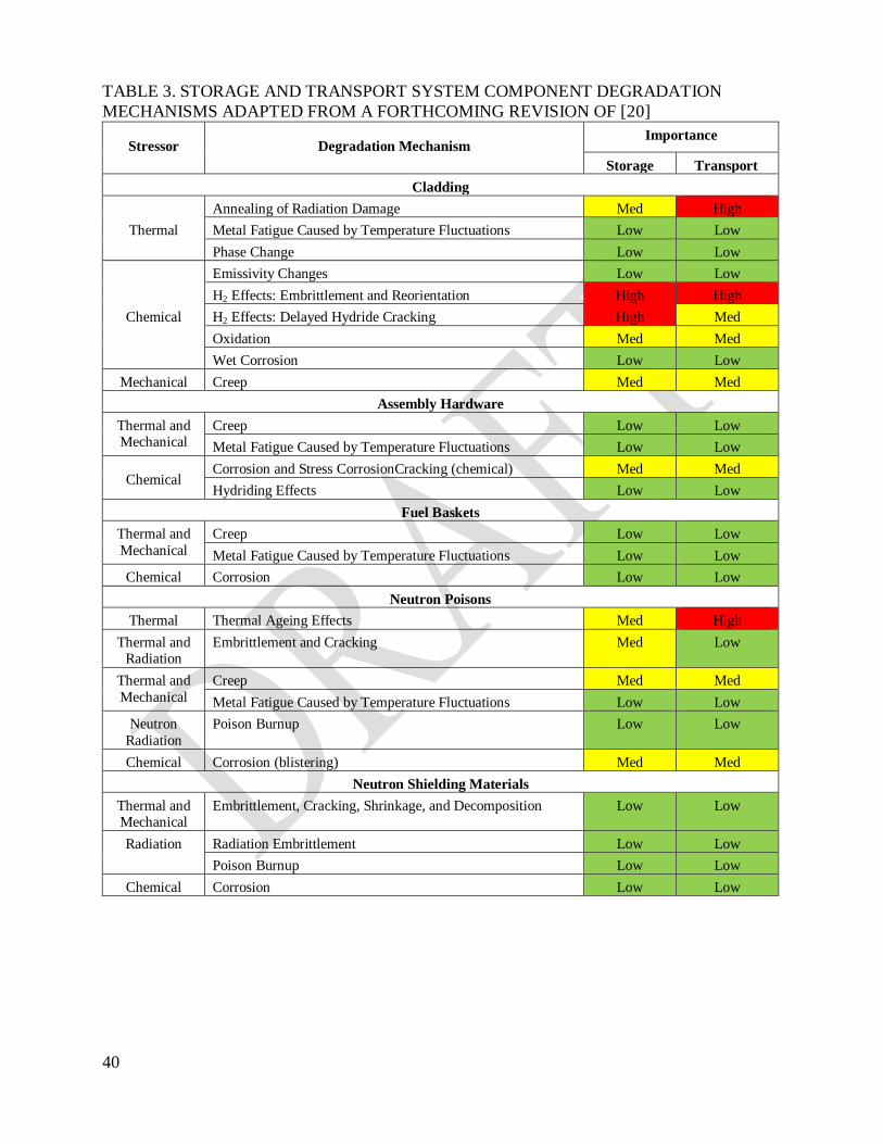
40
TABLE 3. STORAGE AND TRANSPORT SYSTEM COMPONENT DEGRADATION
MECHANISMS ADAPTED FROM A FORTHCOMING REVISION OF [20]
Stressor Degradation Mechanism Importance
Storage Transport
Cladding
Thermal
Annealing of Radiation Damage Med High
Metal Fatigue Caused by Temperature Fluctuations Low Low
Phase Change Low Low
Chemical
Emissivity Changes Low Low
H2 Effects: Embrittlement and Reorientation High High
H2 Effects: Delayed Hydride Cracking High Med
Oxidation Med Med
Wet Corrosion Low Low
Mechanical Creep Med Med
Assembly Hardware
Thermal and Mechanical
Creep Low Low
Metal Fatigue Caused by Temperature Fluctuations Low Low
Chemical Corrosion and Stress CorrosionCracking (chemical) Med Med
Hydriding Effects Low Low
Fuel Baskets
Thermal and
Mechanical
Creep Low Low
Metal Fatigue Caused by Temperature Fluctuations Low Low
Chemical Corrosion Low Low
Neutron Poisons
Thermal Thermal Ageing Effects Med High
Thermal and Radiation
Embrittlement and Cracking Med Low
Thermal and
Mechanical
Creep Med Med
Metal Fatigue Caused by Temperature Fluctuations Low Low
Neutron
Radiation
Poison Burnup Low Low
Chemical Corrosion (blistering) Med Med
Neutron Shielding Materials
Thermal and Mechanical
Embrittlement, Cracking, Shrinkage, and Decomposition Low Low
Radiation Radiation Embrittlement Low Low
Poison Burnup Low Low
Chemical Corrosion Low Low

41
TABLE 3. (Continued)
Stressor Degradation Mechanism Importance
Storage Transport
Container
Welded Canister
Chemical Atmospheric Corrosion High Med
Aqueous Corrosion: General, Localized (pitting, crevice),
SCC, Galvanic
High Med
Bolted Direct-Load Casks
Thermal and
Mechanical
Embrittlement of Elastomer Seals Low Low
Thermomechanical Fatigue of Seals and Bolts Med High
Radiation Embrittlement of Elastomer Seals Low Low
Chemical
Atmospheric Corrosion (including marine environment) High Med
Aqueous Corrosion: General, Localized (pitting, crevice),
SCC, Galvanic
High Med
Inert Fill Gas
Thermal and
Mechanical
Diffusion through Canister Wall NA High
Radiation NA NA
Chemical NA NA
NOTE: The importance ranking given is an example. The importance of degradation mechanisms could be different for storage and transport.

42
TABLE 4. EXAMPLES OF FACTORS AFFECTING SPENT FUEL INTEGRITY
DURING LONG TERM DRY STORAGE ADAPTED FROM [18]
Effective Factor Phenomenon Related Parameter Related Cask Property
Creep By cladding hoop stress according to internal pressure of fuel rod. Cladding
temperature is restricted so that the
accumulated creep strain within a
design storage period may not exceed
1%
Fuel temperature under storage
conditions
The degradation of cask cooling performance
Fuel temperature at
the time of vacuum
drying
Vacuum-drying
conditions (the degree
of vacuum, time)
Hydro
gen
Eff
ect
Embrittlement Affecting cladding mechanical properties by hydrogen absorption in
the atmosphere in a cask
The atmosphere ingredient in the
cask
Degradation of the atmosphere in a cask or
bad drying
Reorientation In excessive hoop stress is acting on the cladding, hydride may precipitate
in the radial direction and may affect
mechanical properties
Fuel temperature under storage
Degradation of cask cooling performance
Axial Diffusion
and Migration
The hydrogen in a cladding may
diffuse according to the direction
temperature gradient of an axis at the degree side of low temperature, and
may affect a mechanical property
Fuel temperature at
the time of vacuum
drying
Vacuum drying
conditions could mean a
fuel thermal transient
Irradiation-hardening
Recovery
The irradiation hardening (higher
strength, lower ductility) recovers
according to recovery of radiation
damage by high temperature
maintenance under storage, At the time of the transport after storage,
when using the mechanical property
of irradiation material for evaluation
of fuel integrity, it is required that
irradiation-hardening recovery should
not occur
Fuel temperature
under storage
Degradation of cask
cooling performance
Fuel temperature at the time of vacuum
drying
Vacuum-drying conditions (the degree
of vacuum, time)
Stress Corrosion Cracking
The combinations with corrosive fuel products like iodine, and the hoop
stress by internal pressure in a fuel
rod
Fuel temperature under storage
Oxidation By reaction with oxygen in the
atmosphere in a cask. May affect the
mechanical properties
The atmosphere in
the cask
Degradation of the
atmosphere in a cask or
bad drying
Helium Generation by Alpha Decay
The helium produced by alpha decay in a fuel pellet causes internal
pressure in a fuel rod to increase
during storage
Fuel temperature under storage
Degradation of cask cooling performance
Physical Properties Change of a Pellet
The lattice constant of a pellet changes with alpha irradiation, and
swelling (volume expansion is
started)
— —

43
1.7.3 Component evaluation
1.7.3.1 Spent fuel
Integrity of spent fuel to be stored in the facility has to be confirmed when the fuel is placed in
the DPC through various means, such as reviewing the data collected during operation of the fuel
in a reactor and by inspection (e.g. sipping, ultrasonic), if necessary.
NOTE: This discussion assumes the spent fuel is intact. Fuel that is not intact or otherwise not
‘typical’ might possibly be placed within a DPC only under special licensing
conditions (e.g. inside a special canister for damaged spent fuel, which is loaded in
specific basket positions).
Also during storage, integrity of fuel cladding has to be maintained for the entire designed
storage period. Moreover, the storage facilities are required to be designed to maintain such
integrity through the designed storage period, while considering ageing deterioration and other
factors.
Thus, during storage, spent fuel integrity is required to be maintained. Integrity in this sense
means fuel cladding is not damaged (cladding with pin holes and hairline cracks, which may
accidentally occur with low frequency, is not regarded as damaged), and integrity of spent fuel
once it is placed in the DPC is properly maintained (excessive deformation or degradation of
material properties have not occurred).
At the beginning, a specific method to evaluate the integrity of spent fuel, as defined above, is
maintained during storage and will be discussed in the license application. As can be seen in
Table 4, damaged fuel could produce a degradation of the cask atmosphere and a degradation of
cooling performance functions.
Spent fuel degradation factors are chemical, thermal, mechanical, and radioactive. Each factor is
evaluated as follows:
(1) Chemical
Chemical factors include the use of specific backfill gases, radiolysis on the internal atmosphere
composition, and remaining moisture after drying. These factors may produce an environment
that favours conditions for stress corrosion cracking or embrittlement phenomena.
Corrosion of fuel cladding due to atmospheric moisture remaining inside the DPC is one of the
examples of degradation caused by chemical factors.
It is assumed that the DPC retains an inert gas environment during storage and the DPC cavity is
dried to an acceptable level prior to the storage period. Thus, if the gas environment within the
DPC is maintained during storage, degradation due to chemical factors is judged to cause no
problem in relation to integrity of spent fuel. If necessary, water-absorbing material may be
placed within the DPC. If ageing of absorbing material is allowed depending on regulations of
the individual country, the degradation behavior of the absorbent needs to be considered during
the storage period.

44
Reference [23] provides supporting knowledge regarding chemical factors.
(2) Thermal
Spent fuel originates all degradation mechanisms due to thermal factors. The effect of thermal
factors decreases with time, depending on the initial heat load, as well as the heat removal
capability.
Examples of degradation due to thermal factors include fuel cladding fracture due to high-
temperature creep deformation, reduction of fuel cladding strength due to recovery of irradiation
hardening under the condition of high temperature, fuel cladding embrittlement due to hydrides
reorientation in association with high-temperature and stress corrosion cracking.
Spent fuel to be stored is assumed to be uranium dioxide fuel or mixed oxide fuel, which is
irradiated in commercial power generation reactors. In addition, scientific and technical
knowledge has to be obtained to determine whether the integrity of fuel cladding can be
maintained for the entire designed storage period. After being permanently removed from a
reactor core, spent fuel is cooled in the nuclear power plant spent fuel pool for a required period.
It is assumed that the DPC is designed to ensure fuel cladding temperature is kept sufficiently
low for the designed storage period (not to exceed a certain fixed level) to maintain fuel cladding
integrity (e.g. by focusing on the cumulative creep deformation of the cladding).
NOTE: Some countries limit maximum spent fuel temperature to a specified value to avoid
hydride reorientation and to limit creep deformation. They could also require a limit
on the number of thermal cycles [24]). Other countries base their maximum spent fuel
temperature limitation on the creep deformation limitation.
It is also assumed that the DPC is designed such that spent fuel decay heat can be appropriately
removed in terms of maintaining spent fuel integrity.
If the fuel cladding temperature is kept below the design temperature, it can be considered that
there is no degradation due to thermal factors for the entire storage period.
Reference [23] provides supporting knowledge and examples regarding thermal factors, including
evaluating damage of the fuel cladding due to progress of creep deformation, decrease of fuel
cladding strength due to recovery of irradiation hardening, fuel cladding embrittlement due to
hydride reorientation, and stress corrosion cracking.
(3) Mechanical
Examples of degradation due to mechanical factors include damage of fuel cladding due to
external forces (incidents or accidents) during storage and transport. The effect of mechanical
factors could increase with time due to changes in fuel cladding properties. To minimize fuel
damage due to mechanical factors, it is important to impose limits on handling activities. Thus,
the incidental and accidental spent fuel conditions have to be evaluated accounting for expected
degradation over the time.
It is required to maintain DPC basic safety functions (containment, shielding, criticality
prevention, and heat removal) when handling the DPC package. During storage, it is required that
45
the DPC is designed to maintain basic safety functions against the design basis loads (e.g. seismic
loads based upon the historical records and field investigation results of the storage site and the
surrounding area). Between the power plant and the storage facility, transport has to be conducted
to satisfy the DPC safety requirements. Impulsive force due to drop, collision, and vibration
during transport, and seismic force due to seismic motion during storage are examples of external
force that might be applied to the DPC.
For the period of transport, DPCs need to be designed to maintain spent fuel integrity against
external forces. For the period of storage, the DPCs need to be designed in such a manner that
they will not undergo external forces beyond those assumed for transport. When expecting
external forces to exceed those during transport, such forces have to be considered in the DPC
design. Confirming the external force actually applied to the DPCs is within the range of those
considered during design ensures spent fuel integrity is maintained against mechanical factors.
(4) Radiation
Radiation affects the fuel pellet structure, especially for high burnup (i.e. higher than 45
GW•d/MTU in United States of America [25]) spent fuel, and produce release of inter- and
intra-granular gases, which may increase cladding internal pressure. As a result, the probability of
occurrence of degradation such as spent fuel creep, spent fuel stress corrosion cracking, and
hydride reorientation may also increase.
In addition, due to the effect of radiation on cladding behaviour, evaluations of incidents and
accidents during storage and transport have to consider increases in strength and decreases in
ductility and fracture toughness of the cladding.
Concerning changes of mechanical properties of the fuel cladding due to neutron irradiation
during storage period, the amount of such irradiation is small in comparison to neutron irradiation
in the reactor. Therefore, there is no problem related to degradation due to neutron radiation
regarding integrity of spent fuel.
Reference [23] provides supporting knowledge regarding irradiation factors.
1.7.3.2 DPC
Ageing deterioration is not expected to affect safety functions for the majority of component
materials currently expected to be used for the DPCs. Table 5 shows DPC component material
for which ageing deterioration needs to be considered.

46
TABLE 5. EXAMPLE OF DESIGN CONSIDERATIONS AGAINST AGEING
DETERIORATION OF COMPONENT MATERIAL
Component Material Material Degradation
Factors Design Consideration
Neutron Shielding
Material
Resin, polyethylene Thermal,
radiation
Establishment of weight loss rate of
neutron shielding material in shielding analysis
Basket Aluminum alloy,
boron-aluminum alloy; neutron
absorbers
Thermal,
radiation
Establishment of allowable stress,
considering ageing deterioration in structural and compositional analysis
for criticality control
Metal Seal Aluminum, silver Chemical,
thermal
Moisture control and establishment
of temperature limit of the metal seal
Elastomeric O-ring Ethylene propylene
diene monomer
(EPDM),
Fluorocarbon rubber (FKM)
Chemical,
radiation,
thermal
Material selection
Cask Body Coating Chemical Inspection and necessary
maintenance
Trunnions Polymer sealants Chemical Inspection and necessary
maintenance
(1) DPC body, trunnions, neutron shielding material, shock absorbers
The DPC needs to be designed to ensure the necessary safety functions during storage and
subsequent transport after storage, while considering potential ageing deterioration of component
material that may occur during DPC package operation.
An appropriate method of verification to confirm that integrity of the DPC is maintained
throughout the storage period for each of these components, as described below.
As the main body of the DPC is important in terms of maintaining basic safety function,
sufficiently reliable materials need to be chosen, considering environment factors such as
temperatures during the design storage period, radiation, and ageing deterioration such as
corrosion, creep, and stress corrosion cracking.
In addition, the DPC components have to be designed to maintain required strength and
performance, and to maintain required safety functions.
If shock absorbers are fabricated for a DPC at a significant period prior to transport of the DPC
package, ageing degradation of the shock absorber material (wood, foam, or aluminium
honeycomb) has to be considered.

47
Polymeric materials for neutron shielding are more sensitive to radiation and temperature than
metals. The radiation exposure conditions for safety related neutron shielding materials can be
determined and compared with the radiation resistance for the particular polymer (if available).
The primary irradiation alteration mechanisms of polymeric material systems in DPC are gamma
radiation induced changes causing scission, crosslinking, or both, that lead to degradation of the
polymer. In addition, the release of gases during degradation (e.g. hydrogen from neutron
shielding material) has to be considered for any potential effect of the gases on safety related
DPC components. References [26–29] provide examples of ageing behaviour studies for neutron
shielding materials.
(2) Basket
The DPC basket is designed to safely contain spent fuel, to ensure proper geometrical
configuration to meet the subcriticality and thermal performance functions, and to allow for fuel
loading and retrievability (if required). Baskets are made from a variety of metals such as
stainless steel, carbon steel, aluminum alloys, or metal matrix composite. When the basket inside
the DPC constitutes a part of the criticality prevention function, it is designed to maintain
structural integrity for the entire period of operation of the DPC package.
Baskets are exposed to decay heat and radiation of the contained spent fuel, and to external forces
caused by vibration due to handling and transfer operations, or off-normal or accident events,
such as earthquakes. Therefore, baskets have to be designed (including material selection) and
manufactured to achieve long term integrity during storage. The environment (which is presumed
to be achieved at the time of sealing) needs to be retained. Hence, when DPCs are loaded in the
power plants (baskets with spent fuel are installed), their cavity has to be dried up to remove
moisture sufficiently, filled with inert gas, and then sealed using multiple lid structures. The
baskets are exposed to the same environment as the spent fuel and are subject to chemical,
thermal, mechanical and radioactive degradation factors, each of which is evaluated as follows:
(a) Chemical
Chemical factors cause many forms of degradation, including basket corrosion due to
exposure from moisture remaining inside DPCs. It is assumed that the DPCs are used
for storage with an inert gas environment.
(b) Thermal
Basket components are subject to creep at normal or off-normal temperatures during
dry storage. Basket components are also subjected to metal fatigue caused by
temperature fluctuations.
The long term effects of thermal ageing on basket components and especially on
neutron poison materials need to be evaluated.
(c) Mechanical
Examples of degradation due to mechanical factors include damage of basket due to
external forces during storage and transport.

48
(d) Radiation
Change of properties of the basket components, including the neutron absorber, due
to neutron irradiation during storage period has to be considered.
(3) Closure system
The DPC closure system, either bolted or welded, serves to seal its contents, and maintain an
inert internal environment. The DPC has to be designed to ensure containment (e.g. considering
ageing deterioration of the seals during storage for bolted closure systems). The DPC needs to be
designed to separate the space containing spent fuel from the outside of the container by
incorporating multiple containment structures in the lid. For some DPCs with bolted closure
systems, the design may enable operators to monitor the containment function, or allow for an
additional lid to be installed in case a lid containment function abnormality is encountered.
Radiation may not affect metal seals (e.g. consisting of coil spring and an inner liner and outer
liner or coiled spring and coated liner) because of the high threshold value required to alter the
mechanical properties of metals. The repulsion force of the coil spring pushes the outer liner on
the seal surface to ensure containment. However, time and temperature effects on metal seals
have to be carefully assessed to ensure continued safe performance. In particular, containment
functions degradation due to corrosion or creep of metal seals has to be considered.
References [23, 30, 31] provide detailed examples of storage cask reopening and inspection.
Concerning corrosion for example, a DPC condition inspection at Fukushima Daiichi Nuclear
Power Station revealed whitening of part of the metal seal surface due to the influence of
moisture remaining on the primary lid flange. Even though there was no abnormality discovered
in the results of the leaktightness test of the primary lid, it was necessary to thoroughly remove
the remaining moisture during preparation of the storage cask. A similar condition inspection at
Tokai Daini Nuclear Power Station showed no whitening on the surface of the metal seal as the
remaining moisture was thoroughly removed from the primary lid, thus confirming validity of
this improvement [23].
Several ageing degradation experiments have been conducted on metallic seals [32–35]. In
addition, a long term containment performance test using full scale lid models was conducted in
Japan from October 1990 to February 2009 [36, 37]. The experiment results provide a basis by
which to evaluate the long term seal performance using the LMP approach.
Furthermore, Ref. [38] provides a demonstration of full scale DPC model performance of
metallic seals in a DPC under transport accident conditions after storage.
The potential for degradation products to affect the integrity of safety related DPC components
has to be considered when using elastomeric seals as they are more sensitive to radiation and
temperature than metals. The radiation exposure conditions for safety related elastomeric seals
can be determined and compared with the radiation resistance for the particular polymer (if
available). The release of gases during degradation (e.g. corrosive fluorine from an elastomeric
seal) has to be considered for potential effects of the gases on safety related DPC components.
49
Usually, elastomeric seals are not included in the safety relevant closure system, and in this case,
the degradation behaviour of elastomeric seals is of minor importance for long term safety.
References [39–42] provide an overview of ageing behaviour studies for elastomeric seals.
(4) Canisters
In some specific designs, the DPC includes a welded canister in which the fuel assemblies are
loaded. The canister provides an additional physical barrier to prevent release of radioactive
material, maintains an inert atmosphere for the container internals to prevent chemical
degradation, and prevents ingress of neutron moderator to provide additional criticality
protection.
The canister is exposed to the DPC internal inert atmosphere. The internal environment of the
canister might be similar to that of the basket; therefore, degradation mechanisms for canisters
within a DPC during storage are considered to be the same as those for the basket. The internal
pressure of canisters might also be taken into account. Based on the four potential stressors
(thermal, radiation, chemical, and mechanical), the identified possible canister degradation
mechanisms during normal or off-normal conditions are wet corrosion, creep, and metal fatigue
caused by temperature fluctuations.
1.7.4 Preshipment inspection after storage period
1.7.4.1 Items to be confirmed before transport of DPC package after storage
Transport after ageing during storage requires careful inspection of the DPC package. When
spent fuel is transported, generally the following items are inspected.
(1) External appearance;
(2) Leaktightness;
(3) Pressure retention;
(4) Dose rate;
(5) Subcriticality;
(6) External surface temperature;
(7) Lifting capability;
(8) Weight;
(9) Condition of contents;
(10) Surface contamination.
Of these, items 3), 5), and 9) are difficult to perform after storage. Alternate means of inspection
can be performed by verification as described in the next section, which in combination with the
ageing evaluation, provide assurance that the DPC package can be safely transported.
50
1.7.4.2 Concept of alternative inspections
Integrity of the DPC and its contents needs to be checked to confirm safety of transport at the end
of the storage period (e.g. by visually checking the condition of the contents and baskets by
opening the DPC lid, or by inspecting the atmosphere inside the DPC before shipment in the
storage facilities).
However, the following facts need to be considered before such an inspection: storage facilities
are very stable and static, activity from spent fuel contained in the DPCs gradually decays by
releasing heat, and visual inspection of internals requires opening the DPC containment
boundary. This action is undesirable not only because it increases radiation exposure or release of
radioactive material risks, but also may increase other risks caused by incidents during handling
of the DPC package.
Consequently, it is more convenient to perform the following inspections based on alternative
approaches when the same level of safety can be ensured as when performing a visual check.
(1) Subcriticality inspection
There is reasonable assurance of no significant deformation or damage if the following points are
confirmed:
(a) The baskets are manufactured following the design in the factory.
(b) Moisture is removed and inert gas is filled according to the design principles during
preparation of the DPC packages in the power plant.
(c) DPC packages passed subcriticality inspection for transport from the power plant to
the storage facility, and there are no abnormal external forces encountered during
transport.
(d) The inert atmosphere of the basket (neutron absorber material) has been maintained
during storage.
As a consequence, when the DPC packages are shipped from the storage facilities that have no
fuel reloading equipment, subcriticality inspection during the preshipment inspection can be
substituted by the documents confirming the previously listed items.
(2) Contents Inspection
When DPC packages are originally shipped from the power plant to the storage facility,
operational records or other documentation already confirm the quantity and configuration of the
spent fuel within the DPC. If there is no factor that will change these conditions, the above
mentioned items can be reconfirmed by using the same records for the shipping of the DPC
packages from the storage facility.
Although the DPC contents cannot be visually checked to determine appearance as they are in a
sealed DPC with inert gas and have the necessary heat removal functions during storage, spent

51
fuel integrity is considered to be maintained and will not be impaired due to chemical, thermal, or
radiological degradation, as explained in Section 1.7.3.1.
Specifically, if the following points are confirmed, it can be judged that no abnormal change in
the condition of spent fuel occurred:
(a) Moisture is removed and inert gas is filled in a way that satisfies the design condition
during preparation of the DPC packages in the power plant.
(b) DPC packages pass the inspection of contents for transport from the power plant to
the storage facility, and there are no abnormal external forces added during transport.
(c) There have been no incidents that may damage the integrity of the spent fuel during
storage (that is, all the items presented in Section 1.7.3.1 were satisfied).
(d) The inert atmosphere of the DPC has been maintained during storage.
As a consequence, when the DPC packages are shipped from the storage facilities, especially if
there is no fuel reloading equipment, the inspection of the contents during the preshipment
inspection can be substituted by the documents that confirm the listed items.
(3) Pressure retaining inspection
Pressure measurements need to confirm that the atmosphere inside the DPCs is within the range
of design principles. However, as the internal cavity of the DPC is sufficiently dried, filled with
an inert gas, sealed by a multiple lid structure, and did not exceed the maximum recommended
temperature, as long as the containment function is maintained throughout the storage period the
original atmosphere can be assumed to be preserved.
Specifically, if the following points are confirmed, the atmosphere inside the DPCs is within the
range assumed at the design stage:
(a) Moisture is removed and inert gas is filled in the way that satisfies the design
principles during preparation of the DPC packages in the power plant.
(b) DPC packages pass the pressure measurement test for transport from the power plant
to the storage facility and no abnormal external force acted during transport.
(c) Containment function of the DPCs was confirmed by the acceptance test in the
storage facility.
(d) Containment function of the DPCs was not lost during storage.
As a consequence, when DPC packages are shipped from the storage facilities, especially those
without fuel reloading equipment, documents confirming items (a) to (d) can substitute for
pressure measurement during the preshipment inspection.

52
1.8 COMPLIANCE WITH REGULATORY REQUIREMENTS
The DPC design specifications are to comply with:
(1) Transport regulations.
(2) Storage and on-site transport requirements that depend on national regulations and on
storage facility design. Meeting the acceptance criteria for storage specified in Section 1.6
shows compliance with the storage requirements.
In general, the DPCSC has to include a complete list of:
(a) Applicable paragraphs of regulations for transport.
(b) Acceptance criteria for storage and on-site transport, as applicable, to the respective
DPC design. Demonstration of compliance with these paragraphs will be verified by
reference to where in the DPCSC compliance is established or other justification.
Sections 1.8.1 and 1.8.2 discuss licensing considerations.
1.8.1 Transport package design approval and storage licensing period
A transport package design approval is usually issued for a period of a few to several years. At
the end of the approval period, the license needs to be revalidated for the next period by
demonstrating compliance with current transport regulations. In contrast, a storage license
(storage facility operational license) could be issued for a period of up to several decades. At the
end of the licensed period, the storage license may be terminated and the facility could be
decommissioned, or the operational license could be extended by a demonstration of compliance
with the current storage facility regulations.
IAEA transport regulations SSR-6 [1] may change from time to time, but with every change gap
analyses between the current and the revised provisions need to be done. Transitional provisions
are provided for the transport regulations where appropriate and/or needed. In that case, DPC
packages licensed under the old transport regulations may be transported when they comply with
the specified arrangement.
Section 1.7 addresses storage license evaluation considerations for determining acceptable
storage period lengths. For example, for a license period of 50 years, it may not be difficult to
evaluate the integrity of the DPC and contents based on available ageing data on spent fuel and
DPC components. On the other hand, for a storage period of 100 years or more, ageing data is not
readily available so an investigation and reevaluation of ageing of spent fuel and the ability of
DPC to continue to perform its safety functions needs to be performed in advance of a
commitment to extended storage and/or transport licenses.
When the transport regulation is changed or new technology is developed during storage, a gap
analysis has to be conducted and the DPCSC has to be updated (see Section 1.12.3 and 1.12.4).

53
1.8.2 License types for storage
Depending on national storage regulations, there are generally two types of storage licenses.
(1) General DPC License (included in a storage license): A stand-alone DPC design licence
issued independently of a specific storage site. The DPC is designed for transport
regulations, specific fuel specifications, and generic storage conditions, including normal
operations, off-normal operations, and accident conditions. A storage facility operator will
choose and implement one or more types of general DPC designs that fit the storage facility
conditions. When storage conditions of a facility differ from generic DPC design
conditions, a separate evaluation needs to be conducted by the storage facility and included
in the facility safety case.
(2) Storage License on the Basis of Site Specific Conditions: The DPC is designed for
transport regulations, spent fuel specific to the site, and specific storage site/facility
conditions. This type of DPC can only be stored at the site for which it is evaluated, and the
license may be a part of the storage facility license. In the safety case for this type of DPC,
safety analyses of the specific storage site/facility conditions are provided.
There may be other licensing methodologies based on national regulations.
Depending upon national regulations, the DPC package may need transport approval before the
start of the storage period.
1.9 OPERATION
The minimum requirements for the following activities need to be fully defined for the DPC
package, as applicable:
(1) Testing requirements (including cold and/or hot tests, when applicable) and controls before
first use.
(2) Testing requirements and controls before each operational step.
(3) Handling and tie down requirements, if applicable.
(4) Requirements for loading and unloading DPC contents.
(5) Requirements for assembling DPC components.
(6) Proposed supplementary equipment and operational controls to be applied during each
operational step that are necessary to ensure the DPC package meets the regulatory
requirements for transport and storage considering heat dissipation, thermal barriers,
duration limits, and temperature limits.
(7) Reestablishing containment boundary functions (change of seals, installation of additional
lids, etc.). Ensuring parts or components are replaced without major impact on the
storage/transport operations and preferably while shielded from the radiation field around
the DPC package.

54
8) The DPCSC scope may include transport after storage with or without direct inspection of
the contained spent fuel.
1.10 MAINTENANCE PLAN
As part of the management system, a maintenance programme has to be established for the DPC
and its contents including and fully defining, as a minimum, the requirements for the following
activities:
(1) Maintenance and inspection requirements before each operational step;
(2) Maintenance and inspection requirements at periodic intervals throughout the lifetime use
of the DPC;
(3) Monitoring and repair of DPC package (e.g. restoration of surfaces, etc.).
The terms ‘maintenance’ and ‘inspection’ used in this publication include examination and
testing. Sections 1.12.2.5 and 1.12.3(5) provide a more detailed discussion of maintenance
programmes.
1.11 EMERGENCY PLAN
In the event of incidents or accidents during radioactive material transport and storage,
emergency provisions, as established by relevant national and/or international organizations, have
to be implemented to protect the public and workers, the environment, and the property. IAEA
Safety Guide TS-G-1.2 [43] contains transport guidelines for such provisions. For storage, the
DPC designer needs to supply information to assist the facility operators in establishing the
emergency plan of the related facility, which may also be included in the safety case for the
storage facility.
Considerations need to include the development of scenarios of anticipated sequences of events,
establishment of emergency procedures, and an emergency plan to deal with each of the
scenarios, including procedural checklists and lists of persons and organizations to be contacted.
This DPCSC has to either interface with the transport or storage facility emergency plans or,
where they do not exist, provide emergency plans.
1.12 MANAGEMENT SYSTEMS
A management system is the plan for the systematic actions necessary to provide confidence that
the storage and transport systems will perform satisfactorily and specified requirements will be
fulfilled. The management system needs to apply to all activities relating to the DPC and its
contents including, but not limited to, the design, fabrication, assembly, inspection, testing,
record management, training, maintenance, repair, modification, use, procurement, handling,
shipping, in-transit storage, short and long term storage, transport after storage, and
decommissioning. The scope of a management system has to clearly identify management roles
and responsibilities during all phases of the storage and transport processes. Useful references
regarding management systems are IAEA Safety Requirements GS-R-3 [44], IAEA Safety Guide
TS-G-1.4 [45], and IAEA Safety Guides TS-G-1.5 [46]

55
Special attention needs to be paid to the ‘Ageing management programme’ in this publication.
New 1.12.1 Maintenance plan
As part of the management system, a maintenance programme has to be established for the DPC
and its contents including and fully defining, as a minimum, the requirements for the following
activities:
(1) Maintenance and inspection requirements before each operational step;
(2) Maintenance and inspection requirements at periodic intervals throughout the lifetime use
of the DPC;
(3) Monitoring and repair of DPC package (e.g. restoration of surfaces, etc.).
The terms ‘maintenance’ and ‘inspection’ used in this publication include examination and
testing. Sections 1.12.2.5 and 1.12.3(5) provide a more detailed discussion of maintenance
programmes.
1.12.1 Lessons learned from literature on ageing management
It has to be ensured in the DPCSC that the entire history of ageing of the DPC and its contents is
considered and that the specified maintenance and monitoring had been completed. For example,
in the possible case where the DPC package has been transported after storage to a second
storage facility, ageing at the first storage facility must be considered for the application of the
storage license at the second storage facility.
While aging problems and their management for DPC are still to be investigated, since the
mid-1980s the The IAEA has worked on ageing problems and their relevance for the safety of
nuclear power plants since the mid-1980s. In 2009 the collective experience of these documents
was summarized with the publication of IAEA Safety Guide NS-G-2.12 [47]. The principle
established in the IAEA Safety Guide can be applied to spent fuel storage facilities.
Figure 5 illustrates this, which indicates the continuous improvement of the ageing management
programme for a particular structure or component, on the basis of feedback of relevant operating
experience, results from research and development, and results of self-assessments and peer
reviews, to help ensure emerging ageing issues will be adequately addressed.
The US NRC addressed ageing management of spent fuel dry cask storage systems in
NUREG-1927, Chapter 3 Aging Management Review [48]. At first, materials of construction and
the environments to which these materials are exposed need to be identified. Next, those ageing
effects requiring either an Ageing Management Programme (AMP) or Time-Limited Ageing
Analysis (TLAA) need to be identified. The Ageing Management Activity (AMA) defines two
methods for addressing potential ageing effects: TLAA and AMP. A TLAA is a process to assess
structures, systems, and components (SSCs) that have a time dependent operating life. At the end
of the identified operating period, the component is typically replaced or renewed. As the DPC
interior and cladding cannot readily be inspected, increased reliance on lessons learned from
research reports in the literature is necessary. Similar to the ageing management of nuclear power
stations, where components are grouped in relation to their safety importance, replaceability, etc.,
56
storage cask components also need to be grouped [49]. The US EPRI presented ageing
management options [50], including additional analyses of degradation mechanisms, enhanced
monitoring and inspection, and, if necessary, repackaging or overpackaging, or both. Recently,
likewise the US Department of Energy addressed ageing management of spent fuel dry cask
storage systems [51]. The goal of this report is to help establish the technical basis for spent fuel
storage beyond the long term and subsequent transport.
OECD/NEA [52] developed the technical basis for commendable practices on ageing
management for SCC and cables in nuclear power plant.

57
FIG. 5. Systematic approach to manage ageing of a DPC.
1.12.2 Essence of the systematic approach to ageing management
This section describes the essence of the systematic approach to DPC ageing management
according to Figure 5.
1.12.2.1 Understanding ageing
Effective ageing management involves taking informed actions to mitigate degradation of SSCs
in DPC storage facilities. Developing an AMP that identifies SSCs subject to ageing processes,
SSCs that need specific actions to mitigate ageing, and the processes to be applied to each SSC is
important to effective ageing management [53].
58
Safety related SSCs are subjected to specific degradation mechanisms and ageing processes that
depend on the component and its operational and environmental conditions, as described in the
Material Performance section. Characteristically in DPC storage system, spent fuel decay heat
and radiation levels will decrease as the storage period continues. Section 1.7.2 describes how
mechanisms will degrade spent fuel cladding and SSC integrity.
1.12.2.2 Plan: Development and optimization of activities for ageing management
Ageing management includes the documentation of relevant programmes and activities and a
description of how the different programmes are coordinated in a systematic manner that
guarantees continuous improvement by incorporating operational experience and relevant
research results.
Ageing issues are best addressed through a systematic programme in which relevant activities for
ageing management are coordinated. The documentation needs to also address maintenance,
control, and inspection and monitoring processes as necessary, as well as the frequency and the
scope of these activities.
1.12.2.3 Do: Managing ageing mechanisms
To limit degradation to an acceptable level, it is necessary to understand potential degradation
mechanisms; suitable operational conditions designed to minimize degradation; control,
inspection, and monitoring techniques that need to be used to detect degradation; evaluation
criteria to determine whether sufficient safety margins remain when degradation is detected; and
methods to manage, repair, or replace degraded components.
1.12.2.4 Check: Monitoring, inspection and assessment
Component evaluations have to demonstrate the validity of the safety functions considering
potential ageing degradation. Safety related SSCs, therefore, include:
(1) Monitoring throughout the storage period;
(2) Periodic inspection for components that may degrade during the storage;
(3) Preshipment inspections.
As a result of these evaluations, a monitoring programme, an inspection programme, and a
maintenance programme, or all, are necessary. Reference [54] provides an example of a periodic
safety review guide.
1.12.2.5 Act: Maintenance
A maintenance programme needs to consider components with a time dependent operating life.
At the end of the identified operating period, the component is typically replaced or renewed.
Effective ageing management involves taking informed actions to mitigate degradation of safety
related SSCs. The actions are based on an understanding of the types of material and
environments at the facility. The key elements of ageing management involve maintenance and
condition assessment.

59
1.12.3 Ageing management programme for DPC storage facilities
An AMP for the storage period addresses uncertainties in the safety relevant functions of the
system that may be impaired by ageing mechanisms. The AMP identifies SSCs that need specific
actions to mitigate ageing and ensures that no ageing effects result in a loss of intended function
of the SSCs, during the license period.
The Generic Aging Lessons Learned (GALL) report [55] provides generic templates for common
nuclear power plant equipment, which can be similarly applied to developing AMPs for SSCs in
the DPC storage facility.
AMPs generally include the following programmes:
(1) Prevention programmes:
A prevention programme can inhibit ageing effects.
(2) Mitigation programmes:
A mitigation programme can slow the effects of ageing. For example, cathodic protection systems
can minimize corrosion of inaccessible metallic components.
(3) Monitoring programmes:
Monitoring means continuous or periodic measurement, including inspection. Inspection means
an examination, observation, measurement, or test undertaken to assess SSCs and materials of the
DPC storage facility.
Ongoing verification in storage facilities is needed to ensure adequate performance of critical
SSCs to meet effective ageing management requirements. Early detection of degradation is
desired before any loss of safety function by either condition monitoring or performance
monitoring.
(a) Condition monitoring:
Condition monitoring will search for the presence and extent of ageing effects.
Examples for DPC storage include determining the condition of concrete structures
and pads, external coatings and housings, and instrumentation and cables.
(b) Performance monitoring:
Performance monitoring will verify the ability of the SSCs to perform their intended
functions. Some examples for specific performance follow.
(i) Shielding:
A DPC operator will obtain historic radiation survey data and evaluate trends.
Either through measurement or analysis, one can adequately assess trends of

60
historical measurements or deviations from calculated radiation levels, which
would indicate shielding degradation. For example, this assessment can be
directed at polymeric neutron shielding materials, because the organic resins
incorporated in DPCs are subject to thermal and radiation induced degradation.
(ii) Containment:
An essential component for containment is the closure system. For DPC storage,
pressure monitoring between cask lids or lid seals can be used. A decreasing
pressure may indicate closure system degradation and has to be considered as an
indicator to implement corrective actions.
(4) Inspection programmes:
An inspection programme will ensure that the safety related components fulfil all applicable
storage requirements and transport requirements:
(a) Periodic inspection of the storage system (e.g. pressure transducers) and preparation
of a report about its condition.
(b) Random inspections of the storage system may be carried out.
(c) The results of recurrent inspections have to be evaluated.
(d) Periodic reassessments of the condition of the storage system with respect to evolving
regulations and technology need to be performed to ensure the storage licensing basis
remains in compliance throughout the storage period, during which ageing
mechanisms may cause changes from the original licensing basis.
(e) The time span for inspection depends on the extent of SSCs degradation, which is
assessed based on the understanding of the degradation mechanisms. Inspections are
made before degradation affects the safety function of the SSCs. During storage, the
time span for inspection may be revised iteratively based on the history of operation,
the results of the past inspection, etc.
After the tsunami disaster at Fukushima Daiichi Nuclear Power Station, a dry spent fuel storage
cask stored on-site was investigated to evaluate potential damage to the cask. This evaluation is
described in Ref. [56]. The evaluation indicated the robustness of the storage cask.
(5) Maintenance programmes:
Operating history, including corrective actions and design modifications, is an important source
of information for evaluating the ongoing condition of pertinent SSCs. One has to discuss such
history in detail. One may consider relevant site specific and industry wide experience as part of
the overall condition assessment of pertinent SSCs.
(a) The AMP ensures that no ageing effects result in a loss of any safety function of the
SSCs.

61
(b) Pressure transducers or pressure switches are used for monitoring the pressure
between the lids or the metal seals. Transducers may be periodically calibrated or
controlled.
(c) If the SSCs are significantly degraded, the AMP might require replacement of the
degraded SSCs based on an assessment of the decrease in the functional performance
of the SSCs.
Note that the maintenance programme will focus on safety related SSCs for technical reasons.
However, the public may be concerned with more visible through non-safety related SSCs as
well (e.g. deteriorated paint).
1.12.4 DPCSC periodic review
Once a DPCSC is developed, the DPCSC needs to be a controlled and include a record of its
compilation and review and its approval by the DPC designer.
Gap analyses considering regulatory changes have to be performed to recognize effects of
subsequent design changes on the DPC already in use, and changes due to developments in
technology have to be monitored. The renewal of the license will be affected by changes in
regulations if new regulations require additional safety considerations. Evolving technological
developments, DPC design changes, or results from research on the effects of ageing mechanisms
on components may, but not necessarily, justify modifications during routine maintenance, at the
renewal of the license, or prior to transport.
The DPCSC has to be kept up to date by periodic review. For DPCs that will be in operation for
several decades, it is important that the essential information on the DPCSC development and
justification are kept present during the lifetime of the DPC. Periodic safety reviews and gap
analyses are to be performed to keep the DPCSC updated; those periodical reviews are an
important element of knowledge management, and force designer and regulators to keep
knowledge on DPC safety present to all relevant institutions. It is recommended to perform gap
analyses for transport package design approval renewal and periodic reassessments of storage
systems in a coordinated and systematic approach (see Section 1.7.1). As the DPCSC is a ‘rolling
process’ the issue versions of separate DPCSC documents or subdocuments have to be clearly
identified in them. It is preferable for the DPCSC to contain a list of the documents it refers to,
including a description of each document version. For the documentation and use of a safety
case, see also in IAEA Safety Guide GSG-3, Chapter 7 [3].
A gap analysis concludes when the DPCSC based upon the new findings is deemed sufficient or
measures are taken to provide the required level of safety.
1.12.5 Record management
Confirmation is required that the prerequisites for and the results of each operational step
involving the DPC storage system were properly inspected, tested, and recorded. A record has to
be available to the operators concerned for each step and to competent authorities for the
confirmation of safety of the system. The availability of such records has to be clearly defined
during the entire storage period and transport after storage in the DPCSC.
62
(1) In the DPC package preparation step, the inspection record confirming that the spent fuel to
be stored is in compliance with applicable specifications has to be provided by the nuclear
power plant operator, and has to be made available for the safety assessment of the DPC
and the integrity of the spent fuel stored to inform subsequent operational steps.
(2) During DPC package preparation, suppliers have to provide the inspection record for DPC
fabrication to nuclear power plant operators to confirm DPC design compliance. The
inspection record has to also be made available for safety assessment of the DPC and spent
fuel integrity in subsequent operational steps.
(3) DPC safety function and spent fuel integrity inspection records may be used to confirm
safety for conducting off-site transport after storage (i.e. the inspection before shipment as
a transport package). For the operational scenario that includes storage at a facility without
fuel retrieval capability, it is especially important to conduct proper inspection or
alternative evaluations at various stages of DPC package preparation. Stages include receipt
of the DPC package at the storage facility, storage and transport after storage with proper
items, and methods established beforehand to confirm safety functions of components
inside the DPC and the integrity of spent fuel without direct observation, such as visual
inspection by opening the DPC lid. The applicable inspection records and evaluation results,
or both, will be properly managed, maintained, and provided upon request.
(4) Preservation and transfer of technology and knowledge to new programme or
organizational staff is essential, particularly for long term storage periods.
(5) Consideration has to be given to the transfer of storage records to transport operations
personnel.
1.13 DECOMMISSIONING
The DPCSC needs to provide an initial plan for decommissioning of the DPC including
consideration for financial arrangements.

63
PART 2: SPECIFIC TECHNICAL ASSESSMENT
Part 2 of the safety case provides the detailed technical analyses to support the demonstration of
compliance with the regulations and acceptance criteria in Part 1 of the safety case, as referred to
in Section 1.8.
Section 2.1 of this guidance provides the common provisions which need to be applied to all
technical analyses to be included in Part 2 of the DPCSC and will not constitute a separate
section of the DPCSC.
Sections 2.2 to 2.6 of this guidance give a list of the technical analyses that may be necessary in
the DPCSC together with their main contents.
2.1 COMMON PROVISIONS FOR ALL TECHNICAL ANALYSES IN PART 2 OF THE
SAFETY CASE
Section 2.1 contains the common provisions that need to be included in each of the technical
analyses in Sections 2.2 to 2.6.
2.1.1 Bases for technical assessment
Each technical analysis in Sections 2.2 to 2.6 of the DPC design being evaluated needs to
precisely reference the DPC design specification and the contents specification defined in
Sections 1.3 and 1.4.
As described in Section 1.5, the impact conditions for the applicable operational scenarios have
to be derived and used in the technical analyses.
The acceptance criteria for the technical analysis and the DPC design criteria in terms of
geometry or performance characteristics need to be defined and justified when necessary
(Section 1.6). The acceptance criteria may be derived from regulatory limits taking into account
an appropriate safety margin. The design criteria have to be chosen from accepted codes and
standards or justified by the designer.
For the technical analyses, the DPC designer has to use properties of new or aged materials
(whichever is most restrictive) while considering factors in Section 1.7. If experimental tests are
used, the aged condition of the DPC package will also be considered.
2.1.2 Description and justification of analysis methods
The safety demonstration of a DPC design can be accomplished by a combination of the
following as appropriate. The methods or standards used in each analysis listed in Sections 2.2 to
2.6 will include a description of the analysis technique used, its limitations, and its accuracy. In
all cases their use has to be justified.
(1) The results of physical testing of prototypes or models of appropriate scale. When a
campaign of tests is implemented for a specific design to be approved by competent

64
authorities, the designer is advised to notify the competent authorities in advance of the
testing programme and they are allowed to witness testing.
(2) By reference to previous satisfactory demonstrations of a sufficiently similar nature. Test
results of designs similar to the design under consideration are permissible if the similarity
can be demonstrated sufficiently by justification and validation.
(3) By calculation, or reasoned argument, when the calculation procedures are generally agreed
to be suitable and conservative. Assumptions made may require justification by physical
testing.
If computer programs are used for the safety analysis, then additional information will be
required to:
(a) Verify/validate the program in terms of the operating platform (computer), method,
modelling approach, and assumptions used.
(b) Justify the applicability of these programs including a statement of possible sources
of errors, particularly for conditions for which sufficient verification has not yet been
provided.
(c) Assess the effects of modelling assumptions and simplifications as well as any other
parameters that may influence the calculated results.
(d) Special attention has to be paid to situations for which the existing or available
database is not applicable (due to missing or insufficient data). In those cases, the use
of calculation methods and assumptions needs to be conservative to provide margins
of safety to compensate.
(e) In general, program validation is accomplished by comparing with analytical
solutions and with other validated programs (benchmarking). More guidance can be
found in Ref. [4], Section VI.14.
2.1.3 Analysis of DPC design
The DPC design has to be assessed, as appropriate, with the results subject to an appropriate and
identified sensitivity analysis with stated levels of accuracy.
It is probable that more than one accident and its consequences need to be considered to ensure
various safety functions that may be fulfilled by different components of the DPC design comply
with regulatory requirements.
Other factors that may have a consequential effect on the safety functions have to be analysed.
These may be corrosion, combustion, pyrophoricity or other chemical reactions, radiolysis, phase
changes, etc.
2.1.4 Comparison of acceptance criteria with results of analysis
The results of the analyses detailed in Section 2.1.3 have to be compared with the acceptance
criteria and DPC design criteria and regulatory compliance has to be justified accordingly.

65
2.2 STRUCTURAL ANALYSES
2.2.1 Reference to DPC design for structural analysis
The design of the DPC and the description of the contents have to be referenced according to
Section 2.1.1.
2.2.2 Assumptions for structural analysis
The structural behavior has to be demonstrated for normal operation, off-normal operation, and
accidents. For off-site transport, the conditions to be analyzed are given in the international
modal regulations or national transport regulations. According to IAEA transport regulations
SSR-6 [1], analysis is required for routine conditions of transport (RCT, no incident), normal
conditions of transport (NCT, including minor mishaps), and accident conditions of transport
(ACT), each defined by testing conditions. For on-site transport and storage the conditions to be
addressed need to be taken from the analysis of the operational conditions, incidents, and
accidents that must be considered for these activities as described in Section 1.5.2.
Most of the acceptance criteria for transport are derived from IAEA transport regulations SSR-6
[1]. In addition, the criteria are to be derived from national regulations or as agreed upon with
national regulators.
In general, components of the DPC and its contents important to safety need to have sufficient
structural capability to accommodate the combined loads anticipated during normal and
off-normal events and to withstand the worst case loads under accident level events to ensure the
following acceptance criteria are met:
(1) Criticality;
(2) Release of radioactive materials to the environment;
(3) Direct radiation doses to the public or workers and derived dose rates;
(4) Heat removal.
This position does not necessarily imply that all the structures important to safety survive without
permanent deformation or other damage. The results of the structural analysis have to include
determination of the maximum extent of potentially significant accident deformations and any
permanent deformations, degradation, or other damage that may occur, and have to clearly
demonstrate that no damage would render the system performance unacceptable.
2.2.3 Description and validation of methods for structural analysis
2.2.3.1 Experimental drop testing
(1) Determine the most damaging test orientation and sequence and analyse the effect on the
containment, criticality safety and shielding functions.

66
(2) For the mechanical ACT, the sequence of 9 m drop tests and 1 m puncture tests need to be
analysed or performed to maximise damage and loading of the DPC (in terms of
deformation, stress, strain, acceleration and damage before the second test) while
considering different DPC components (cask body, closure system, impact limiters, basket,
etc.) and contents. The drop test positions and sequences are to be selected to maximise
loading of the individual DPC components and contents.
(3) An assessment needs to be made of storage facility conditions defined in Section 1.5 and of
the DPC package configuration. The following aspects need to be considered:
(a) Drop tests which maximise the stresses and acceleration.
(b) Drop tests which maximise the deformation.
(c) Drop tests that maximise the damage to orifices, notably by a puncture bar. The
containment components in the orifices are often thin and more liable than the body
to be damaged.
(4) For drop tests performed with a scale model of a DPC package, the following needs to be
considered:
(a) Similar or conservative geometry and component/material properties are to be used.
(b) Demonstration that the results of the drop test with the scale model DPC can be
correlated to the original design.
(c) It may be necessary to increase drop heights to simulate the total potential energy that
would have been received by the DPC package at full scale. This is particularly so
where the characteristic deformation of the structure is not negligible in comparison
to the drop height [57].
(d) Appropriate geometric scaling of all containment system components is important
[58], including:
Metallic seals: same design, materials and similar force-deflection characteristic.
Elastomeric seals: the similarity has to be based on the useful elasticity taking
into account the compression set. The change of material properties with
temperature and radiation has to be considered.
The scaling of tightening torques for bolts of the scale model DPC package has
to consider friction, precision of torques, and technical limitations in an exact
geometric and physical scaling of the containment system components.
Similar welding seams.
In the case of scale model DPC package drop testing with significant
deformations of impact limiters or yielding targets, the correlation to the
67
behaviour of the full scale DPC package performance has to be carefully
justified.
2.2.3.2 Structural analysis calculations
(1) Calculations using computation models are to be verified and validated. It must be
demonstrated that input parameters (material laws, characteristic values, boundary
conditions, etc.) describe sufficiently and precisely the actual conditions which the DPC
package may experience.
(2) If uncertainties exist regarding important input parameters (e.g. material laws),
conservative design calculations including the possible range of material properties have to
be performed to assess limiting values.
(3) All data used (material laws, boundary conditions, load assumptions, etc.) and calculation
results are to be documented in detail.
2.2.4 Structural assessment
The following are some of the points that need to be considered in a structural analysis.
(1) An assessment needs to be made of the mechanical behaviour (including fatigue analysis,
brittle fracture, creep, and effects of ageing during storage) under RCT, NCT, and SCT
before and after storage and under normal, off-normal, and accident conditions of storage
for:
(a) DPC components of the containment system;
(b) DPC components that provide radiation shielding;
(c) DPC components for criticality control;
(d) DPC components for which their performance will have a consequential effect upon
(a), (b), and (c);
(e) Packaging attachments used for lifting the DPC package (RCT and NCT, and normal
and off-normal conditions of storage);
(f) Packaging attachments used for restraining the DPC package to its conveyance
during transport (RCT and NCT only);
(g) External features used in special storage configurations such as DPC package
anchored to the pad.
This includes the mechanical stability of the contents and any structure that is used to
maintain its geometry if necessary for the criticality safety assessment. Other important
criticality safety relevant items to be considered include water leaking into or out of the
DPC, the rearrangement of the fissile material, and the degradation of neutron absorbers.
68
(2) Demonstration of the compliance with performance standards is accomplished by methods
listed in Section 2.1.2.
(3) The mechanical properties of the materials considered need to represent the range of
mechanical properties of the DPC components considering (e.g. i) the applicable
temperature ranges between the minimum and the maximum temperature of the respective
DPC components and ii) the loading rates to which the components may be subjected in
transport and storage).
(4) The following points have to be considered in the assessment of the mechanical behaviour
of the DPC components:
(a) The effects on the DPC package response due to variations in the shock absorbing
properties of the impact limiter material (wood, polymers, plaster, concrete, etc.) with
consideration given to the temperature range and the moisture content of the impact
limiters.
(b) The possibility of brittle fracture of components at the minimum design temperature.
(c) The strength of the lid bolts has to be justified for accident conditions.
(d) It is preferable to avoid plastic deformation of containment system components such
as bolts, seal seats, etc. Plastic deformation analysis would require complex proofs
concerning the mechanical behaviour of the components and sufficient seal seating.
(e) Possible damage of seals due to vibrations or sliding of the lid has to be evaluated.
(f) The condition of the containment system has to be determined to enable Section 2.4
requirements to be demonstrated within the temperature range concerned.
(g) Retention of sufficient thermal protection to guarantee the safety functions of DPC
components for accident conditions has to be evaluated.
(h) Verification of the mechanical behaviour of the fuel and the internal structure.
(i) The effect of the thermal loads on the mechanical behaviour of the DPC components
are to be considered (e.g. thermal stresses and strains and interactions between DPC
components due to changes in dimensions).
(j) Proof of the ability to withstand the maximum pressure (taking into account fire and
radiolysis, physical changes, chemical reactions, etc.).
(k) Verification that the DPC can withstand water immersion. For storage, impact on the
DPC due to potential floods at the facility site needs to be considered.
(l) Analysis of the influence of any devices described in Section 1.4(e) on the
performance of the DPC package in accident conditions.

69
(5) The spent fuel integrity and geometries required to maintain subcriticality and heat
removal, and its related confinement system, have to be maintained and verified throughout
the storage period.
(6) Consideration has to be given to potential cumulative effects of radiation on materials
likely to be subjected to significant radiation fields. In addition, potential thermal effects on
material degradation need also to be considered. Other ageing effects such as stress
corrosion cracking, creep, and stress relaxation have to be considered (Section 1.7).
(7) Static, dynamic, and seismic loads have to be considered in the design of casks or baskets.
2.3 THERMAL ANALYSES
2.3.1 Reference to DPC design for thermal analysis
The design of the DPC and the description of the contents need to be referenced according to
Section 2.1.1.
2.3.2 Assumptions for thermal analysis
The thermal behavior has to be demonstrated for normal operation, off-normal operation, and
accidents. IAEA transport regulations SSR-6 [1] lists off-site transport conditions that have to be
analyzed. According to SSR-6, analysis is required for RCT, NCT, and ACT, each defined by
testing conditions. For on-site transport and storage, the conditions to be addressed have to be
taken from the analysis of the operational conditions, incidents, and accidents that have to be
considered for these activities as described in Section 1.5.2.
Most of the acceptance criteria for transport are derived from IAEA transport regulations SSR-6
[1].In addition, the criteria are also derived from national regulations or as agreed upon by the
national regulators.
In general, components of the DPC and its contents important to safety need sufficient heat
removal capability to ensure the following acceptance criteria are met:
(a) External surface temperature of the DPC package for transport purposes have to meet
national and international transport regulations requirements.
(b) Criticality.
(c) Release of radioactive materials to the environment.
(d) Direct radiation doses and dose rates to the public or workers.
2.3.3 Description and validation of methods for thermal analysis
The following are some of the points that need to be considered in a thermal analysis.

70
(1) An assessment needs to be made of the thermal behaviour under RCT, NCT, and ACT each
before and after storage, and under normal, off-normal, and accident conditions of storage
for:
(a) The containment system;
(b) Components providing radiation shielding;
(c) Components providing criticality control;
(d) Components for which their performance will have a consequential effect upon (a),
(b), and (c).
This assessment includes the fissile material thermal behaviour and any structure used to
maintain the geometry of the fissile material for the criticality safety assessment.
(2) Evaluate the effects of insolation for a period of 12 hours according to SSR-6, para. 657
[1]. Averaging insolation over 24 hours is not acceptable. For outside storage, the same
effects need to be considered.
(3) Consider the presence of protective systems liable to impede heat dissipation in RCT (e.g.
tarpaulins, canopies, additional screens, outer packaging [containers, boxes, etc.]), if
applicable.
(4) For storage, as well as 3), consider adjacent DPC packages.
(5) Justify simplifying assumptions used for calculation (for example the absence of
trunnions).
(6) The DPC package in accident conditions needs to be analysed in the position (horizontal or
vertical) which is most thermally challenging to the DPC and contents.
(7) The solar insolation before and after the fire test needs to be considered as defined in
SSR-6, para. 728 [1]. For storage, a different solar insolation may be applicable.
(8) The absorptivity of the external surface of the DPC will not be lower than 0.8 without
additional justification (see SSR-6, para. 728(a) [1]) during and after the fire test to account
for deposits upon the DPC surface. The absorptivity will also not be lower than the possible
maximum value of the emissivity.
(9) The evaluation of the minimum and maximum temperatures of the various components of
the DPC has to take account of all the possible positions for the contents.
(10) The time dependent temperatures of fuel and components have to be determined during the
total storage period. This information can be used for the evaluation of ageing effects
(Section 1.7).
(11) The profile of burnup distribution and decay in irradiated fuels has to be taken into account
in the thermal analyses.

71
(12) The influence of combustible materials that generate additional heat input and affect the
fire duration has to be taken into account for safety analyses.
(13) Analysis of the influence of the devices specified in Section 1.4(e) in fire conditions on the
performance of the DPC package needs to be performed, if applicable.
(14) It has to be demonstrated that the spare volume in the seal grooves allows for thermal
expansion unless appropriate justification is provided.
(15) Operational conditions during DPC loading as well as storage and transport have to be
described. The heat removal capability in combination with operational conditions (which
can be very important during the loading procedure, for example if using vacuum drying)
has to be such that the temperature of the spent fuel assembly, including that of the
cladding, does not exceed the maximum allowable value. In addition, other safety related
components of the DPC also have to not exceed their maximum allowable temperatures.
This can be demonstrated by measurements or calculations.
(16) Analysis has to consider processes foreseen to degrade or impair the system over time.
Changes to thermal properties related to ageing (Section 1.7), for example changes to the
internal gas composition, need to be considered.
(17) All thermal loads and processes resulting from the spent fuel decay heat have to be given
appropriate consideration in the design. Typical items for consideration include:
(a) Thermally induced stresses;
(b) Internally and externally generated pressures;
(c) Heat transfer requirements;
(d) Effect of temperature on subcriticality.
2.3.4 Thermal assessment
The thermal assessment has to be conducted for all operational scenarios planned for the DPC
package (Section 1.5.2). Sections 2.3.1 to 2.3.3 describe conditions to be considered for the
thermal analysis.
2.3.4.1 Experimental thermal test
Experimental thermal tests for transport have to be carried out in accordance with guidance
provided in SSG-26 para. 728 [4]. Analogous methods may be applied to storage situations.
(1) When thermal analysis is based on test results, show that the temperature measurements
were performed at thermal equilibrium.
(2) When the thermal test is made in a furnace and where some DPC components burn, the
concentration of oxygen present in the environment of the furnace has to be controlled to

72
be the same as that obtained in a hydrocarbon fire. In addition, control of heat input has to
be considered thoroughly.
2.3.4.2 Thermal analysis calculations
(1) Calculations using computational models are to be verified and validated. It must be
demonstrated that input parameters (material properties, characteristic values, boundary
conditions, etc.) describe sufficiently and precisely the bounding conditions that the DPC
package may experience.
(2) The safety margins on temperature results derived using numerical modelling need to be
commensurate with the uncertainty of the numerical model.
(3) If uncertainties exist regarding important input parameters (e.g. material properties),
conservative design calculations including the possible range of material properties need to
be performed to assess limiting values.
(4) All data used (material properties, boundary conditions, etc.) and calculation results are to
be documented in detail.
2.4 ACTIVITY RELEASE ANALYSIS
2.4.1 Reference to DPC design for activity release analysis
The design of the DPC and the description of the contents have to be referenced according to
Section 2.1.1.
2.4.2 Assumptions for activity release analysis
The limitation of activity release has to be demonstrated for NCT and ACT, and normal operation,
off-normal operation, and accidents during storage. IAEA transport regulations SSR-6 [1]
provide the off-site transport conditions that have to be analysed. According to SSR-6 [1],
analysis is required for NCT (including minor mishaps) and ACT, each defined by test conditions.
For on-site transport and storage, the conditions to be addressed have to be taken from the
analysis of the operational conditions, incidents, and accidents that must be considered for these
activities at the affected facilities as described in Section 1.5.2.
The basic condition of the DPC package for each step in the operational scenario has to be taken
from the history of the fuel and the DPC as described in Section 1.5.1, including irradiation of the
fuel and all ageing processes of the DPC, its inserts and seals, and the fuel after loading
(Section 1.7). Then, based on this state for the assessment conditions given above, the influence
on the properties of the DPC, the inserts and seals, and the fuel elements have to be determined
(refer to analysis results from Sections 2.2 and 2.3). The mechanical and thermal impact
conditions (DPC package orientation during tests or accidents, temperatures, etc.) have to be
selected to lead to the configuration with maximum release. These conditions may differ from
those leading to the most severe situation regarding dose rate calculation or criticality safety;
therefore these conditions need to be carefully selected and justified in the DPCSC.
Basic information needed to assess activity release is as follows:

73
(1) The leakage rate of the containment system of the DPC based upon leakage rate test (see
Section 1.9) and upon structural and thermal analysis (Sections 2.2 and 2.3).
(2) The releasable source term (gaseous, aerosols, volatiles) of the contents of the DPC based
upon a structural integrity assessment of the spent fuel (including cladding) and the
physical and chemical properties of radionuclides inventory (taking into account ageing,
release processes, pulverization, and other changes in physical form). The determination of
the releasable source term needs to consider:
(a) Mechanical resistance of the spent fuel assemblies with respect to the internal
pressure;
(b) The risk of rupture due to creep of the rods under the effect of the internal pressure,
taking into account the mechanical properties of the fuel rods for the temperature
conditions and for the history (burnup rate, cooling time, etc.) of the spent fuel
assemblies;
(c) The risk of rupture of the rods from mechanical impacts, taking into account the
mechanical properties of the fuel rods and cladding for the temperature conditions
and the history (burnup rate, cooling time) of the spent fuel assemblies;
(d) Analysis of the condition of the spent fuel assemblies (for example, the risk of
cracking or rupture of the fuel rod at their ends), if necessary for the safety
demonstration;
(e) Condition of internal canister or basket for spent fuel (damaged or not);
(f) Fission gas release rate from spent fuel;
(g) The presence of debris and of aerosols in the DPC cavity following the analysis of
risks of rupture and cracking of the spent fuel cladding;
(h) The formation of aerosols.
(3) Pressure condition inside the DPC (resulting from possible radiolysis, corrosion, cladding
failure, temperature, etc.).
(4) For off-site transport, a reduction of ambient pressure to 60 kPa has to be considered for
evaluation of activity release according to in SSR-6, Para. 645 [1]. For on-site transport and
storage, the minimal atmospheric pressure of the site has to be considered.
Relevant values for activity release limits have to be taken from SSR-6 [1] or derived from
criteria for the facility (Section 1.8).
Example for transport: IAEA transport regulations SSR-6 [1], para. 659 specify the restrictions
for the loss of radioactive contents from Type B(U) or Type B(M) packages under NCT and ACT
in terms of activity per time: limits of 10-6
A2 per hour for NCT and A2 (10 A2 for 85
Kr) per week
for ACT have to be kept by an appropriate function of the containment system.

74
2.4.3 Description and validation of calculation method for activity release analysis
Activity release has to be calculated for NCT and ACT, and normal operation, off-normal
operation, and accident conditions during storage. Some of these calculations usually are done by
using computer programs.
The selection or calculation of activity release source term for a DPC package has to be based on
a bounding case of the radioactive inventory in the DPC.
The computer program or calculation method used has to be accurately specified. The validation
of the computer program for application to the DPC design and contents under consideration has
to be demonstrated (Section 2.1.2(c)).
The validation for source term calculations may be based on the SFCOMPO database [59] or as
approved by the national competent authority.
References [60] and [61] provide additional activity release guidance.
2.4.4 Activity release calculations
2.4.4.1 Containment system of a DPC
The closure system, which is part of the containment boundary of most DPCs, is comparable: two
flanges with inserted bolts and a metallic or elastomeric seal in between (for one lid flange). An
additional metallic or elastomeric seal is required to create the necessary volume for leak tests via
test ports. For example, the double jacket metal seals used for the DPC designs in Germany
consist of a circular spiral spring encased in two jackets; the inner layer is made of stainless steel,
the outer of aluminium or silver. Material for elastomeric seals usually used is fluorocarbon
rubber (FKM) or ethylene propylene diene monomer (EPDM) rubber.
2.4.4.2 Leakage mechanism and mode of calculation
Direct measurements of radioactive releases from a DPC package are not feasible. Therefore, the
common method for the specification of leaktightness is to relate the admissible limits of activity
release to equivalent standardized leakage rates.
Releasable radioactive material might be in the form of gas, liquid, solid particles, or a
combination of these, and can be released through leaks or, in case of DPC with elastomeric
seals, by permeation. Miscellaneous models are available for different leak designs and types of
fluid. The ‘one capillary leak model’ has become accepted [62] in the field of package design
testing. The maximum permissible activity release rate can be expressed in terms of a maximum
permissible capillary leak diameter. The following equations describe the flow rates through a
capillary.

75
(1) Gas flow
The modified Knudsen equation is valid for the whole range of molecular, transitional, and
viscous laminar gas flow.
where
Q is leakage rate [Pa m³ s-1
];
a is capillary length [m];
D is capillary diameter [m];
M is relative molecular mass [kg mol-1
];
pd is downstream pressure [Pa];
pu is upstream pressure [Pa];
R is universal gas constant [8.31mol-1
K-1
];
T is temperature [K] (fluid);
µ is dynamic viscosity of the fluid [Pa s].
In addition to gas, particles could be released, but below a standardized leakage rate of
QSLR < 10-4
Pa m3
s-1
the release of fuel or crud particles is negligible due to a choking of the
capillary [63].
(2) Liquid flow
Poiseuille’s law is applied for the flow of liquids through a capillary:
where
L is liquid leakage rate [m3 s
-1].
A DPC design at conventional temperature and pressure conditions is considered to be
liquid-tight below a standardized leakage rate of QSLR = 10-5
Pa m³ s-1
[64].
(3) Permeation
Permeation of radioactive gases through metals is negligible for release calculation [65]. If
elastomeric seals are used, gas permeation is an additional release pathway:
where
QP is permeation rate [Pa m³ s-1
];
P is coefficient of permeation [m² s-1
];
a
D
M
TRpp
a
DQ du
3224
6
2
2
)(
128
du ppaµ
DL
4
128
pl
APQP
76
p is partial pressure difference [Pa];
l is thickness of the permeable material [m];
A is area of the permeable material normal to the gasflow [m3].
The DPC designer has to demonstrate that the design leakage rates specified for the
miscellaneous conditions do not exceed the maximum permissible standardized leakage rates.
The ISO 12807 [66] or ANSI N14.5 [67] standards provide the basis for the calculation.
There are seven substantial steps to determine:
1. Total releasable activity;
2. Equivalent A2;
3. Permissible activity release rate;
4. Activity release due to permeation;
5. Maximum permissible volumetric leakage rate;
6. Maximum permissible equivalent capillary leak diameter;
7. Permissible standardized leakage rate.
2.4.4.3 Design leakage rates
Design leakage rates identify the efficiency limits of the containment system under NCT and
ACT and normal, off-normal, and accident conditions of storage, and are deduced from tests with
real DPC packages, DPC models, or DPC components (e.g. flange assemblies). Component tests
are important for the demonstration of the worst case conditions and for statistical validation.
Impact loads (see Table 6 for off-site transport resulting from the regulatory mechanical and
thermal tests) can result in deformations, displacements or degradation (or combination of these)
of DPC components involving an unloading and/or a movement of the lids and/or seals as a result
of rotation or lateral sliding. The leakage rate can increase as a consequence.

77
TABLE 6. EXAMPLE OF IMPACTS TO BE CONSIDERED FOR OFF-SITE
TRANSPORT THAT CAN INFLUENCE THE LEAKTIGHTNESS OF THE
CONTAINMENT SYSTEM
IAEA Transport Regulations
SSR-6 [1] Loadings to be Considered
RCT Paras 613 and 616
Acceleration in radial, axial, and vertical directions;
Operational temperature and pressure.
NCT Paras 722 to 724
RCT and
Free drop from a height of 0.3 m (mass 15 t);
Five times the maximum weight (during 24 hours);
6 kg steel bar drop from the height of 1 m;
Maximal normal operating pressure and temperature.
ACT Paras 726 to 730
RCT, NCT and combination of:
Free drop from a height of 9 m;
1 m puncture test;
800°C, 30 min thermal test separately;
Water immersion test (including 200 m).
(1) Metallic seals
A specific leakage rate (depending on the type of metallic seal) that attests the regular assembly
status (leaktightness) has to be demonstrated by a leakage test after assembling of the closure
system after loading and before any transport, or the containment function has to be demonstrated
by other means (e.g. taking into account monitoring).
This specified leakage rate has to be accepted for normal operation during storage and RCT.
Off-normal operation, storage related accidents / NCT and ACT: For NCT and ACT the design
leakage rates depend on the test safety assessment results.
The vertical 0.3 m drop (package mass 15 t) under NCT can cause short term elastic
deformation of the bolts that can lead to a short time relaxation of the lid flange. Component tests
have shown that after a repeated compression, provided that no seal dislocation occurs, the
specified leakage rate is achievable again [68].
Leakage rates measured after a repeated compression including a seal displacement (rotation) are
considerably higher [68]. For implementing the specified leakage rate as design leakage rate for
NCT, DPC designers need to demonstrate that there is a sufficient compression load on the seal
at any time during the drop event to prevent a movement of the seal. Otherwise the higher values
have to be used.
The design leakage rates for ACT for DPC designs need to be deduced using, for example,
measurements after drop tests with DPC models, numerical analyses of influences of thermal
impacts, component tests simulating a lateral and a radial seal displacement, or other similar
methods.

78
Mechanical and thermal safety analyses have to be used to determine the maximum widening
between the flange surfaces of the sealing system which can be caused, for example, by
deformation of bolts, bending of the lid and/or the DPC body flange, or by dissimilar thermal
expansion of lid and DPC body material (due to different coefficients of thermal expansion or
inhomogeneous heating under thermal impact). For RCT it is important that such widening does
not exceed the useful elastic recovery of the seal, called ru, because the efficiency of the seal is
exhausted above this range. A gap greater than ru will cause the standardized leakage rate to
exceed specifications.
Specified NCT and ACT design leakage rates can only be accepted if the possible widening after
impact loading is smaller than ru (a short term decompression above ru is possible). Figure 6
illustrates the useful elastic recovery of ru.
DPC designers are required to consider the influence of temperature and time to justify
conservative ru values.
FIG. 6. Compression and decompression cycle of the Helicoflex seal for illustration of the useful
elastic recovery (ru = e2-e1). Reproduced courtesy of Technetics Group[69].
(2) Elastomeric seals
Elastomeric seals show a very advantageous behaviour under mechanical stresses and are able to
compensate for flange dislocations over a wide range of deformations. The design leakage rate
when using elastomeric seals is mainly limited by permeation.
A critical point for these seal materials is their behaviour at low temperatures and the limited
lifetime at high temperatures (see also Section 1.7). DPC designers have to justify the critical low
temperature for failure and lifetime at high temperature when using new mixtures of elastomeric
materials.
2.4.4.4 Source term
Spent fuel rods contain radionuclides in the form of gas, volatiles, and fuel particles, which are
only releasable through a breach in the cladding. Additional particles known as Chalk River
Unidentified Deposit (CRUD), on rods surfaces can contribute to the releasable content.

79
The activities of the radionuclides, which have to be considered for release calculation, can be
calculated by using a computer program, such as ORIGEN [70] or ORIGEN-ARP from the Scale
code package [71]. The calculations of the activities of the radionuclides need to lead to the
maximum quantities of releasable radionuclides (in terms of A2). The calculation case to
determine the source term for the release analysis could thus be different from the case to
determine the source term for the external dose rate calculation.
The release of activity from the fuel rods into the DPC internal cavity depends on the chemical
and physical properties of the radionuclides, the fuel characteristics, the conditions of the
cladding tubes and on the amount and properties of CRUD.
Based on experiments and examinations, conservative values for the prediction of the source term
for leakage rate calculation were deduced in a NUREG report [72] (Table 7).
TABLE 7. RELEASE FRACTIONS USED TO PREDICT THE SOURCE TERM FOR
RELEASE CALCULATIONS FROM SPENT FUEL TRANSPORT PACKAGES [72]
Release fractions NCT ACT
Fraction of gases released due to a cladding breach fG 0.3 0.3
Fraction of volatiles released due to a cladding breach fv 2 × 10⁻⁴ 2 × 10
-4
Fraction of fuel fines released due to a cladding breach fF 3 × 10⁻⁵ 3 × 10
–5
Fraction of CRUD that spalls off of rods fc 0.15 1.0
Fraction of rods developing cladding breaches fB 0.03 1.0
These values are determined for burnups of 33 to 38 GWd/tHM. In recent years, fuel is being
driven to burnups of 65 GWd/tHM or higher. DPC designers are requested to investigate the
possible influence of a higher burnup and other parameters on the release fractions and to justify
the release fraction used for their specific cases.
(1) Release fraction of gases and volatiles
The generation of 85
Kr and 3H dominates the gas release and is proportional to the burnup. The
release of fission gases from fuel occurs through grain boundaries and depends on temperature
and fuel microstructure. The release fraction increases disproportionally with a higher burnup.
Measurements have shown that a fraction of 30% is still a conservative value up to a burnup of
100 GWd/tHM. For a burnup of 80 GWd/tHM, a release fraction of 15% is justifiable [73].
For volatiles, dominated by 137
Cs, 134
Cs, 106
Ru, and 90
Sr, a release fraction of 0.02% is acceptable
as conservative estimate even for higher burnup considering the very low vapour pressures of the
relevant isotopes.
(2) Release fraction of particles
Changes in the fuel characteristics after a higher burnup can affect the particle size distribution.
Also the amount and the characteristics of CRUD fines are impacted by higher burnups. Design

80
leakage rates of spent fuel transport and storage casks equipped with metal seals are, in most
cases, small enough to prevent particle release.
(3) Fraction of rods developing cladding breaches
The number of rods developing cladding breaches is a very important parameter for the release
calculation. Such breaches enable not only the release of gas, volatiles, and fuel particles into the
DPC interior, but also an increase of the internal cavity pressure. In this context, cladding
breaches imply only fine cracks, in contrast to the criticality assessment domain where more
extensive damages such as fuel rod ruptures are of main interest.
Higher burnups cause a higher cladding material embrittlement due to the uptake of hydrogen
and a higher tendency for hydride reorientation, as well as a growing oxide layer and
coalescences of fuel and cladding material.
Due to the lack of experimental results, the failure rate of fuel rods cladding under ACT for the
containment assessment is assumed to be 100%. Until now there was no need for a more detailed
examination with reduction of the failure fraction for ACT in mind because the release
calculations for most of the DPC designs show a sufficient margin to the required level. The
influence of the degraded rods properties due to higher burnups on the failure probability of the
cladding under NCT, for example after a 0.3 m drop, is still an open question.
DPC designers are requested to present additional evidence supporting a conservative value of
the fraction of rods developing cladding breaches under NCT. In case of a lack of additional
analysis, the number of higher burnup spent fuel assemblies permitted for one loading has to be
limited to ensure a sufficient safety margin in calculation. For very high burnups an
encapsulation of the fuel rods could be requested.
The assessment for storage may be based partially on assessment for transport, but the following
also need to be considered:
(a) Components of the containment system may be different (e.g. two lids).
(b) Normal conditions (e.g. temperature, pressure) may be different for storage.
(c) Accident conditions depend on the storage facility and DPC configuration (aircraft
crash, no shock absorbers, etc.) and are different from transport conditions.
(d) Permanent monitoring takes place for many designs, and there is equipment and
instructions for the case of leakage (using this methodology could be an additional
option to limit the activity release under normal conditions).
(e) Ageing of DPC components (Section 1.7).
(f) Changes of the fuel assembly characteristics (radionuclides composition, cladding,
release of activity) during storage.
(g) Pressure increase and radiolysis in the DPC during storage.
81
2.4.4.4 Other guidance
References [66, 67], and [5], paras 657.5 to 657.13 provide additional activity release calculation
and leakage rate measurement guidance.
2.5 EXTERNAL DOSE RATES ANALYSIS
2.5.1 Reference to DPC design for dose rates analysis
DPC designers have to reference according to Section 2.1.1 the DPC design and a description of
its contents.
2.5.2 Assumptions for dose rates analysis
The external dose rates have to be calculated for normal operation, off-normal operation, and
accidents. IAEA transport regulations SSR-6 [1] provide the required off-site transport conditions
to be analysed. According to SSR-6, analysis is required for RCT (incident free), NCT (including
minor mishaps), and ACT, each defined by testing conditions. For on-site transport and storage,
the conditions to be addressed have to be taken from the analysis of the operational conditions,
incidents, and accidents that must be considered for these activities as described in Section 1.5.2.
The basic condition of the DPC package for the given step in the operational scenario needs to be
taken from the history of the fuel and the DPC as described in Section 1.5.1 including irradiation
of the fuel and all ageing processes of the DPC, its inserts, and the fuel after loading (Section 1.7).
Then, based on this state for the assessment conditions given above, the influence on the
properties of the DPC, the inserts, and the fuel elements has to be determined (refer to
Sections 2.2 and 2.3). The mechanical and thermal impact conditions (DPC package orientation
during testing, temperatures, etc.) have to be selected to lead to the worst configuration (highest
dose rates). These conditions may differ from those leading to the most severe situation regarding
activity release or criticality safety; therefore, these conditions have to be carefully selected and
justified in the DPCSC.
Basic information for the assessment of the external dose rates is the:
(1) Source term of the DPC contents taking into account the integrity of the spent fuel
(including cladding) and internal components (basket, inner container, etc.);
(2) DPC shielding components integrity.
External dose rates limits have to be taken from international or national regulations or
acceptance criteria given by the competent authorities.
IAEA transport regulations SSR-6 [1] define off-site transport criteria, including dose rate limits
for a single DPC package, as well as dose rate limits for the surface and the surrounding area of
the conveyance. As it is usually difficult to meet the limits for the conveyance later by additional
shielding (need for heat transfer) or distances (conveyance size limits) DPC designers are
recommended to take into account the conveyance limits in the DPC design phase. The
assessment of the dose rate and dose rate increase ratio for RCT, NCT, and ACT need to assume

82
a radioactive content that would create the maximum dose rate at the surface of the DPC at
distances defined in the regulations.
For on-site transport and storage, the dose rate criteria have to be derived according to national
regulations specifically applied for the storage site for the public and workers (Section 1.6).
2.5.3 Description and validation of calculation method for dose rates analysis
Dose rates have to be calculated for RCT, NCT, and ACT and normal operation, off-normal
operation, and accident conditions of storage.
The selection or calculation of the radiation source term for a DPC package has to be based on a
bounding case of the radioactive inventory of the spent fuel assemblies (including structural
materials) and the activated materials of the DPC.
A computer program usually calculates external dose rates. The computer program used has to be
suitable and accurately specified. The main features of the program have to be described.
Dose rate calculation methods have to be qualified and validated for the specific conditions of the
DPC package to which they are applied (Section 2.1.2). One possible method of validation is to
compare dose rate calculations against DPC package measurements.
Dose rate calculations have to take into account current ICRP recommendations [74].
2.5.4 Dose rate calculations
The assessment of the dose rate and dose rate increase ratio have to assume a radioactive content
that would create the maximum dose rate at the surface of the DPC and at distances defined in the
regulations.
The modelling of the shielding components and sources has to be fully described in the DPCSC
for all cases analysed.
Dose rate analyses have to take into account:
(1) Dose rate analysis has to be performed in such a way that specific DPC surface areas with
maximum dose rates are identified and analysed (e.g. trunnion areas, areas containing gaps
that give rise to radiation streaming, areas adjacent to reduced shielding, and other areas
with the potential of increased dose rates due to DPC design).
(2) Based on dose rate analysis, the maximum radioactive contents of the DPC have to be
justified (or limited) by various methods and parameters (e.g. nuclide specific activity
values, nuclide specific source terms for gamma and neutron emitters, minimal cooling
time, and others), as appropriate.
(3) Burnup axial profile has to be conservatively taken into account for neutron and gamma
sources along the shielding model, as applicable.

83
(4) Geometry of the modelled source term of the DPC contents has to take into account a
structural integrity assessment of the spent fuel (including cladding) and internal
components (basket, inner container, etc.). Based on this assessment, possible relocation of
the contents has to also been taken into account.
(5) DPCSC has to correctly include the secondary gamma radiation from neutron sources in
the dose rate analysis.
(6) Radiation from activated materials from fuel assembly components (e.g. top and bottom
nozzles) and from inserts (e.g. control rods, thimble plugs) has to be taken into account and
appropriately modelled.
(7) If measurements are applied to demonstrate compliance with the dose rate limits, then
representative radiation sources have to be selected, as well as appropriately calibrated dose
rate measuring techniques used for gamma and neutron radiation.
(8) The expected areas for peak dose rates to be checked before shipment (Section 1.9) have to
be derived from the results of dose rate calculation to ensure compliance with transport
regulations.
(9) The integrity of the DPC shielding components and their behaviour under normal and
accident conditions have to account for the structural, thermal, and ageing analyses. For
example, if applicable:
(a) Consider thermal response of materials providing radiation protection under fire
conditions;
(b) Provide the possible effects due to lead slump after mechanical impact, taking into
account the temperature of the lead.
For storage, the following would also be considered:
(1) Degradation of the shielding components with time (e.g. ageing of neutron shielding
material; Section 1.7);
(2) The storage configuration may differ from transport configuration (e.g. additional
shielding);
(3) The modelled source term depends on time in storage.
2.6 CRITICALITY SAFETY ANALYSIS
2.6.1 Reference to DPC design for criticality safety analysis
The design of the DPC and the description of the contents need to be referenced according to
Section 2.1.1. If burnup credit is used in the demonstration of criticality safety, all necessary
information about the irradiation conditions has to be included as mentioned in Section 2.1.1.
84
2.6.2 Assumptions for criticality safety analysis
The criticality safety has to be demonstrated for RCT, NCT, and ACT and normal operation,
off-normal operation, and accidents during storage. For off-site transport, the conditions to be
analysed are given in IAEA transport regulations SSR-6 [1]. According to SSR-6, analysis is
required for RCT (incident free), NCT (including minor mishaps), and ACT, each defined by
testing conditions. For on-site transport and storage, the conditions to be addressed have to be
taken from the analysis of the operational conditions, incidents, and accidents that must be
considered for these activities as described in Section 1.5.2.
The basic condition of the DPC package for the given operation has to be taken from the history
of the fuel and the DPC as described in Section 1.5.1, including irradiation of the fuel and all
ageing processes of the DPC, its inserts, and the fuel after loading (Section 1.7). Based on this
state, DPC designers have to determine the influence of the assessment conditions given above
on the properties of the DPC, the inserts, and the spent fuel (Sections 2.2 and 2.3). The
mechanical and thermal impact conditions (DPC package orientation during testing, temperatures,
etc.) have to be selected to lead to the most reactive configuration. These conditions may differ
from those leading to the most severe situation regarding activity release or dose rate calculation;
therefore, these conditions need to be carefully selected and justified in the DPCSC.
It is very important to determine the amount of water inside the DPC cavity that has to be taken
into account. As an example, IAEA transport regulations SSR-6 [1] for off-site transport require
assuming water can leak into all DPC void spaces. Avoidance of water leakage into the DPC, i.e.
water exclusion, can only be assumed when:
(1) The design incorporates at least two high standard water barriers (which remain watertight
during the tests for NCT, followed by the tests for ACT and including an immersion under
0.9 m of water for 8 hours) to prevent such leakage, even as a result of error.
(2) A high degree of quality control in the manufacture, maintenance, and repair of the DPC
and its inserts is demonstrated.
(3) Tests to demonstrate the closure of each DPC package before each shipment are specified.
According to IAEA Safety Guide SSG-26, para. 680.2 [5] leakage criteria for ‘water tightness’
need to be set in the DPCSC, and accepted by the competent authority. These criteria have to be
demonstrated to be achieved in the tests, and achievable in the production models.
For on-site transport and storage, the moderation conditions to be taken into account have to be
derived from national regulations and the analysis of the operational conditions, incidents, and
accidents.
As unmoderated low-enriched uranium is always subcritical, the presence or absence of water in
the cavity of a DPC has an extremely high impact on criticality safety. A failure in the design
phase to determine the most severe accident conditions leading to water ingress into the cavity
may result in unacceptably strong neutron multiplication in case of an accident (e.g. if the
criticality safety assessment assumed water exclusion, and neutron absorbers or other features for
preventing criticality were not included in the design). It is therefore recommended to assume

85
water ingress in the criticality safety demonstration for all cases, even if not required by the
regulations.
If more than several grams of water are to be assumed in the DPC cavity, the behaviour of the
inserts (for instance, degradation of neutron absorbers) and the fuel are very important for the
criticality safety assessment. If water in-leakage is not to be taken into account, it may be
possible to demonstrate criticality safety independently from the condition of the inserts and fuel.
This may be a solution for cases where it is difficult to describe the behaviour of the fuel in
accident conditions due to ageing.
Criticality safety for DPC packages needs to be demonstrated by calculating the effective neutron
multiplication factor (keff) of a single DPC package and arrays of DPC packages in the conditions
defined above. Criteria for keff limits have to be taken from national regulations or acceptance
criteria given by the competent authorities and have to consider uncertainties, conservatism, and
margin of safety. IAEA Safety Guide SSG-26, paras. VI.35 – VI.38 [5] and German standard,
DIN 25712 [14] provide keff acceptance criteria guidance.
2.6.3 Description and validation of the calculation method for criticality safety analysis
DPC package criticality safety has to be demonstrated by calculating the effective neutron
multiplication factor for a single DPC package and arrays of DPC packages for RCT, NCT, and
ACT and normal operation, off-normal operation, and accident conditions of storage. Such
calculations are usually done using computer programs.
The computer programs used have to be accurately specified (including the cross section data
library used and, for example, the modules used for the calculations). The main features of the
program need to be described.
The validation of the computer program for application to the DPC design under consideration
has to be demonstrated. The validation has to be based on calculations for a sufficiently large
database of critical and subcritical experiments. The experiments need to be similar to the DPC
design parameters, materials (fuel composition, DPC insert materials, DPC materials, etc.), and
neutron spectra (taking into account the moderation ratios of the different configurations of the
DPC and its contents). The validation has to lead to the calculation of an upper safety limit for
keff. IAEA Safety Guide SSG-26 [5], paras. VI.22 – VI.29, and NUREG/CR-6361 [75], Chapter 4
provide advice regarding the validation. ICSBEP International Handbook [76] collects a large
database of critical and subcritical experiments. Ref. [77] provides advice on how to select
suitable experiments and how to check their similarity.
For situations when the qualification database is not applicable (due to missing or insufficient
data) DPC designers may have to use conservative calculation methods and assumptions to
provide margins of safety to compensate for the lack of data.
2.6.4 Criticality safety calculations
Criticality safety has to be demonstrated for all operational scenarios planned for the DPC
package (Section 1.5.1). The criticality safety demonstration needs to consider the conditions
described in Sections 2.6.1 to 2.6.3.
86
The criticality safety demonstration must analyse (according to IAEA transport regulations
SSR-6, para. 688 [1]) a single DPC package reflected by at least 20 cm of water, as well as
arrangements of several DPC packages. SSR-6 specifies the hypothetical arrays of (identical)
DPCs to be considered by the DPC designer for off-site transport. For storage, the arrangements
to be considered would be taken from applicable regulations and the layout of the storage site
including the analysis of the operational conditions, incidents, and accidents. If different DPC
designs or contents are present at the storage site, their possible interaction needs to be analysed
(for DPC packages with thick walls made from iron or steel, the interaction between different
DPC packages can usually be neglected, but nevertheless this case needs to be analysed). The
arrangements to be taken into account for on-site transport are site specific and need to adhere to
the regulations for such operations.
Moderation conditions play an important function in the criticality analysis and unless moderator
exclusion is assumed (Section 2.6.2), the DPC designer has to consider optimum moderation in
each calculation, including complete, partial, and preferential (limited to the conditions possible
during credible accident scenarios) flooding of the DPC.
For some specific DPC designs, if the interaction between DPC packages close to each other
cannot be neglected, the optimum moderation conditions of an array of DPC packages could be
different from the optimum moderation conditions for the single DPC package. Moderation
conditions between DPC packages and within the DPC packages have to be analysed.
It is important to verify that storage and transport criticality safety assessments are based on the
correct configurations, which are usually different for the different operations and scenarios
(aircraft impact, shock absorbers, etc.).
The following typical items, if applicable, would be considered in the criticality analysis
(however, this list is not exhaustive — see also SSG-26, Appendix VI [5]):
(1) Justification of the criticality analysis needs to account for all possible physical and
geometric configurations (dimensional tolerances, positions of the components, etc.).
(2) Usually keff increases in cases of fuel rod lattice expansion and may increase by axial
shifting of fuel rods and collection of fuel released from broken fuel rods in free space in
the DPC cavity. Such configurations need to be carefully considered.
(3) If natural or depleted uranium could be present in the fuel elements, it needs to be taken
into account in the criticality safety justification with appropriate assumptions relative to
quantities and location of the uranium within the DPC.
(4) For DPC packages for which subcriticality is demonstrated without considering the ingress
of water into the cavity under ACT and accident conditions of storage, the criticality safety
of a single DPC package under RCT, NCT, and normal operation conditions of storage
with water ingress needs to be demonstrated to cover possible situations (including human
error).

87
(5) Consequences of human error/accidents during loading on conditions of the DPC and its
contents need to be considered (for example, an erroneously loaded assembly with higher
enrichment or lower burnup if burnup credit is taken into account).
(6) All structural materials that could increase the neutron multiplication need to be taken into
account.
(7) Rearrangement, degradation, loss of efficiency, and depletion of neutron absorber material
need to be taken into account (see also ageing in Section 1.7).
In contrast to the classic approach to criticality demonstration assuming unirradiated fuel, a
second approach (burnup credit) may be used when considering a more realistic fuel reactivity
under certain conditions, including the selection of nuclides and burnup conditions, computer
programs, and isotopic validations.
Information on the use of burnup credit in criticality safety assessments of spent fuel can be
found in publications from the NEA WPNCS Expert Group on Burnup Credit Criticality Safety
(see the list of references including IAEA meetings on this topic at
http://www.nea.fr/html/science/wpncs/buc/index.htm)

88
REFERENCES
[1] INTERNATIONAL ATOMIC ENERGY AGENCY, Regulations for the Safe Transport
of Radioactive Material 2012 Edition, IAEA Safety Standards Series No. SSR-6, IAEA,
Vienna (2012).
[2] INTERNATIONAL ATOMIC ENERGY AGENCY, Predisposal Management of
Radioactive Waste, IAEA Safety Standards Series No. GSR Part 5, IAEA, Vienna
(2009).
[3] INTERNATIONAL ATOMIC ENERGY AGENCY, The Safety Case and Safety
Assessment for the Predisposal Management of Radioactive Waste, IAEA Safety
Standards Series No. GSG-3, IAEA, Vienna (2013).
[4] INTERNATIONAL ATOMIC ENERGY AGENCY, Storage of Spent Nuclear Fuel,
IAEA Safety Standards Series No. SSG-15, IAEA, Vienna (2011).
[5] INTERNATIONAL ATOMIC ENERGY AGENCY, Advisory Material for the IAEA
Regulations for the Safe Transport of Radioactive Material, IAEA Safety Standards
Series No. SSG-26, IAEA, Vienna (2013).
[6] Technical guide on package design safety reports for the transport of radioactive
material, recommended by the European Association of Competent Authorities on the
transport of radioactive material (EACA), European PSR Guide ISSUE 2 (September
2012), http://ec.europa.eu/energy/sites/ener/files/documents/20131018_trm_technical_guide.pdf
[7] INTERNATIONAL ATOMIC ENERGY AGENCY, IAEA Safety Glossary, 2007
Edition, IAEA, Vienna (2007).
[8] NUCLEAR REGULATORY COMMISSION, Classifying the Condition of Spent
Nuclear Fuel for Interim Storage and Transportation Based on Function, Division of
Spent Fuel Storage and Transportation, Interim Staff Guidance -1, Revision 2, USNRC,
Washington, D.C. (2007).
[9] INTERNATIONAL ATOMIC ENERGY AGENCY, Management of Damaged Spent
Nuclear Fuel, IAEA Nuclear Energy Series No. NF-T-3.6, IAEA, Vienna (2009).
[10] UNITED STATES OFFICE OF THE FEDERAL REGISTER, Title 10, US Code of
Federal Regulations, Part 72, Licensing Requirements for the Independent Storage of
Nuclear Fuel, High-level Radioactive Waste, and Reactor-related Greater than Class C
Waste, US Government Printing Office, Washington, D.C. (2012).
[11] RECOMMENDATION OF THE NUCLEAR WASTE MANAGEMENT
COMMISSION (ESK), “Guidelines for dry cask storage of spent fuel and
heat-generating waste (revised version of 10.06.2013)”
http://www.entsorgungskommission.de/englisch/downloads/eskempfehlungesk30llberev
fassung10062013en.pdf
[12] NUCLEAR SAFETY COMMISSION OF JAPAN, Decision: Safety examination
guidelines for spent fuel interim storage facilities using metallic dry casks; and
Long-term integrities of metallic dry casks and their contents at the spent fuel, NSCJ,
Tokyo (2002).
[13] KATO, K. SAEGUSA, T., Long-term Sealability of Gaskets for Spent Fuel Storage
Casks (No.2), CRIEPI Rep. No.U94029, Central Research Institute of Electric Power
Industry, Tokyo (1998).
[14] DIN 25712:2007-07: Kritikalitätssicherheit unter Anrechnung des Brnnstoffabbrands bei
Transport und Lagerung bestrahlter Leichtwasserreaktor-Brennelemente in Behältern

89
(Criticallity safety taking into account the burnup of fuel for transport and storage of
irradiated light water reactor fuel assemblies in casks)
[15] AMERICAN SOCIETY OF MECHANICAL ENGINEERS, Boiler and Pressure Vessel
Code, Section III Rules for Construction of Nuclear Facility Components, Division 3
Containment for Transportation and Storage of Spent Nuclear Fuel and High Level
Radioactive Material and Waste, ASME, New York (2012)
[16] JAPAN SOCIETY OF MECHANICAL ENGINEERS, Codes for Construction of Spent
Fuel Storage Facilities – Rules on Transport/Storage Packagings for Spent Nuclear Fuel
– (in Japanese), JSME, Tokyo (2007).
[17] NUCLEAR REGULATORY COMMISSION, Materials Aging Issues and Aging
Management for Extended Storage and Transportation of Spent Nuclear Fuel,
NUREG/CR7116, USNRC, Washington, D.C. (2011).
[18] INTERNATIONAL ATOMIC ENERGY AGENCY, Optimization strategies for cask
design and container loading in long-term spent fuel storage, IAEA-TECDOC-1523,
IAEA, Vienna (2006).
[19] ELECTRIC POWER RESEARCH INSTITUTE, Extended Storage Collaboration
Program International Subcommittee Report: International Perspectives on Technical
Data Gaps Associated with Extended Storage and Transportation of Used Nuclear Fuel,
EPRI, Palo Alto, CA (2012).
[20] MCCONNELL, ET AL., Extended Dry Storage of Spent Fuel: Technical Issues: A USA
Perspective, Nuclear Engineering and Technology, Vol. 43 No. 5, (2011).
[21] HANSON, B, Alsaed, H., Stockman, C., Enos, D., Meyer, R., Sorenson, K. Gap
Analysis to Support Extended Storage of Used Nuclear Fuel, FCRD-USED-2011-
000136 Rev.0, PNNL-20509, Washington, D.C. (2012).
[22] ASTM C1562 – 10, “Evaluation of Materials Used in Extended Service of Interim Spent
Nuclear Fuel Dry Storage Systems.”
[23] MINISTRY OF ECONOMY, TRADE AND INDUSTRY, Long-term Integrity of the
Dry DPCs and their Contents in the Spent fuel Interim Storage Facilities, Japanese
Nuclear and Industrial Safety Subcommittee of the Advisory Committee for Natural
Resources and Energy Nuclear Fuel Cycle Safety Subcommittee Interim Storage
Working Group and Transportation Working Group, Tokyo (2009).
[24] NUCLEAR REGULATORY COMMISSION, Cladding Considerations for the
Transportation and Storage of Spent Fuel, Spent Fuel Project Office Interim Staff
Guidance -11, Revision 3, USNRC, Washington, D.C. (2003).
[25] USNRC, Backgrounder on High Burnup Spent Fuel, http://www.nrc.gov/reading-
rm/doc-collections/fact-sheets/bg-high-burnup-spent-fuel.html
[26] IIDA, T., TANIUCHI, H., FUJISAWA, K., Evaluation Method for Long Term
Degradation of Neutron Shield for Transport/Storage Packaging, Kobe Steel Ltd.
[27] VON DER EHE, K., JAUNICH, M., WOLFF, D., BÖHNING, M., GOERING, H.,
Radiation induced structural changes of (U)HMW polyethylene with regard to its
application for radiation shielding,” PATRAM 2010 (Proc. Int. Symp., London) (2010).
[28] NIZEYTUMANA, F., BELLENGER, V., ABADIE, P., ISSARD, H., Thermal Ageing
of Vinylester Neutron shielding Used in Transport/Storage Casks, PATRAM 2010 (Proc.
Int. Symp., London) (2010).
[29] WOLFF, D., VON DER EHE, K., JAUNICH, M., BÖHNING, M., Performance of
neutron radiation shielding material (U)HMW-PE influenced by gamma radiation,
PSAM11 & ESREL 2012, (2012).
90
[30] NUCLEAR REGULATORY COMMISSION, Dry Cask Storage Characterization
Project – Phase 1: CASTOR V/21 Cask Opening and Examination, NUREG/CR-6745,
INEEL/EXT-01-00183, USNRC, Washington, D.C. (2001).
[31] NUCLEAR REGULATORY COMMISSION, Examination of Spent PWR Fuel Rods
after 15 Years in Dry Storage, NUREG/CR 6831, ANL 03/17, USNRC, Washington,
D.C. (2003).
[32] VÖLZKE, H., PROBST, U., WOLFF, D., NAGELSCHMIDT, S., SCHULZ,
S., Investigations on the Long Term Behavior of Metal Seals For Spent Fuel Storage
Casks, Institute of Nuclear Material Management, Deerfield, IL (2011).
[33] SASSOULAS, H., MORICE, L., CAPLAIN, P., ROUAUD, C., MIRABEL, L., BEAL,
F., Ageing of metallic gaskets for spent fuel casks: Century-long life forecast from
25,000-h-long experiments, Nuclear Engineering and Design 236, Issue 22, (2006).
[34] PROBST, U., HAGENOW, P., VÖLZKE, H., WOLFF, D., WOSSIDLO, P., ABBASI,
B., ACHELPÖHLER-SCHULTE, A., SCHULZ, S., Investigation of seal effects
according to axial compression variation of metal seals for transport and storage casks,
Packaging, Transport, Storage & Security of Radioactive Material, Vol. 19, No 1.,
(2008).
[35] VÖLZKE, H., PROBST, U., WOLFF, D., NAGELSCHMIDT, S., SCHULZ, S., Seal
and Closure Performance in Long Term Storage, PSAM11 & ESREL 2012, (2012).
[36] WATARU, M., SHIRAI, K., SAEGUSA, T., ITO, C., Long-term Containment Test
using Two Full-Scale Lid Models of DPC with Metal Gaskets for Interim Storage, 3rd
East Asia Forum on Radwaste Management: 2010 EAFORM, Geongju, Koera, (2010).
[37] WATARU, M., SHIRAI, K., SAEGUSA, T., ITO, C., Long-Term Containment
Performance Test of Metal Cask, 2011 International High Level Radioactive Waste
(IHLRWM) Conference, Albuquerque, NM (2011).
[38] YOKOYAMA, T., KAWAKAMI, H., UCHIYAMA, N., YASUDA, M., MATSUOKA,
S., Assessment of Integrity of a Dual-Purpose Metal Cask after Long-Term Interim
Storage: Seal Performance under Transport Conditions, Packaging, Transport, Storage
and Security of Radioactive Material, Vol.16 No.3, (2005).
[39] KOWALEWSKY, H., DROSTE, B., NEUMEYER, T., BURNAY, S.G., BALL, M.H.,
MORTON, D.A.V., SMITH, P.N., TUSON, A.T., Safety assessment of leak tightness
criteria for radioactive materials transport packages, Patram 1998 (Proc. Int. Symp.,
Paris) (1998).
[40] GERNSTEIN, R., GILLEN, K. T., Fluorosilicone and Silicone O-ring Aging Study,
SANDIA REPORT SAND2007-6781, Sandia National Laboratories, Albuquerque, NM
(2007).
[41] HOFFMAN, E. N., SKIDMORE, T. E., DAUGHERTY, W. L., DUMM, K.A., Long
Term Aging and Surveillance of 9975 Package Components, SRNL-STI-2009-00733,
Savannah River National Laboratory, SRNL-STI-2009-00733, Aiken, SC (2009).
[42] SKIDMORE, T. E., Performance Evaluation of O-Ring Seals In The SAFKEG 3940A
Package In Kams (U), WSRC-TR-2003-00198, Rev. 0, Savannah River Technology
Center, Aiken, SC (2003).
[43] INTERNATIONAL ATOMIC ENERGY AGENCY, Planning and Preparing for
Emergency Response to Transport Accidents Involving Radioactive Material, IAEA
Safety Standards Series No. TS-G-1.2 (ST-3), IAEA, Vienna (2002).

91
[44] INTERNATIONAL ATOMIC ENERGY AGENCY, The management system for
facilities and activities - Safety Requirements, IAEA Safety Standards Series No.
GS-R-3, Vienna (2006).
[45] INTERNATIONAL ATOMIC ENERGY AGENCY, The Management System for the
Safe Transport of Radioactive Material, IAEA Safety Standards Series No. TS-G-1.4,
IAEA, Vienna (2008).
[46] INTERNATIONAL ATOMIC ENERGY AGENCY, Compliance Assurance for the
Safe Transport of Radioactive Material, IAEA Safety Standards Series No. TS-G-1.5,
IAEA, Vienna (2009).
[47] INTERNATIONAL ATOMIC ENERGY AGENCY, Ageing Management for Nuclear
Power Plants, IAEA Safety Standards Series No. NS-G-2.12, IAEA, Vienna (2009).
[48] NUCLEAR REGULATORY COMMISSION, Standard Review Plan for Renewal of
Spent Fuel Dry Cask Storage System Licenses and Certificates of Compliance- Final
Report, NUREG-1927, USNRC, Washington, D.C. (2011).
[49] ERHARD, A., VÖLZKE, H., WOLFF, D., Ageing Management, IAEA Tech. Mtg. Very
Long Term Storage of Used Nucl. Fuel, IAEA, Vienna (2011).
[50] KESSLER, J., Used Fuel Extended Storage: What the U.S. Industry Wants from DOE,
NEI Conference, Electric Power Research Institute, (2011).
[51] CHOPRA, O.K., DIERCKS, D., MA, D., SHAH, V.N., TAM, S-W, FABIAN, R.R.,
HAN, Z. and LIU, Y.Y., Managing Aging Effects on Dry Cask Storage Systems for
Extended Long-Term Storage and Transportation of Used Fuel, FCRD-UFD-2013-
000294 Rev.1, ANL-13/15, Washington, D.C. (2013).
[52] NEA/CSNI/R(2010)15 “Technical Basis for Commendable Practices on Ageing
Management.”
[53] INTERNATIONAL ATOMIC ENERGY AGENCY, Understanding and Managing
Ageing of Material in Spent Fuel Storage Facilities, Technical Reports Series No.443,
IAEA, Vienna (2006).
[54] ESK, ESK recommendations for guides to the performance of periodic safety reviews for
interim storage facilities for irradiated fuel elements and heat-generating radioactive
waste (PSÜ-ZL) (2010.11).
http://www.entsorgungskommission.de/englisch/downloads/eskepanlage1esk14homepag
ee.pdf
[55] NUCLEAR REGULATORY COMMISSION, Generic Ageing Lessons Learned Report,
NUREG-1801, USNRC, Washington, D.C. (2001).
[56] TOKYO ELECTRIC POWER COMPANY, Report of the Investigation Results of the
First Dry Storage Cask at Fukushima Daiichi Nuclear Power Station, TEPCO, Tokyo
(2013).
[57] WILLE, F., BALLHEIMER, V., DROSTE, B., Suggestions for correct performance of
IAEA 1 m puncture bar drop test with reduced scale packages considering similarity
theory aspects, Packaging, Transport, Storage & Security of Radioactive Materials,
Vol. 18, No .2 (2007).
[58] BALLHEIMER, V., KOCH, F., KUSCHKE, C., DROSTE, B., Similarity aspects for
closure systems in reduced scale package drop testing, Packaging, Transport, Storage &
Security of Radioactive Materials, Vol. 21, No.1 (2010).
[59] ORGANIZATION FOR ECONOMIC CO-OPERATION AND DEVELOPMENT,
Spent Fuel Isotopic Composition Database (SFCOMPO), OECD/NEA, Paris,
www.nea.fr/sfcompo.

92
[60] DEPARTMENT OF ENERGY, DOE Handbook airborne release fraction/rates and
respirable fractions for non reactor nuclear facilities, USDOE, Washington, D.C. (1994).
[61] NUCLEAR REGULATORY COMMISSION, Severe Accidents in Spent Fuel Pools in
Support of Generic Safety Issue 82, NUREG/CR-4982, USNRC, Washington, D.C.
(1987).
[62] KOWALEWSKY, H., Modelling Contents and Leaks- Advantages and Limitations,
PATRAM 1995, (Proc. Int. Symp., Las Vegas), USA (1995).
[63] HIGSON, J., MOULTAN, R. J., VAUGHN, R. A., Containment of radioactive powders
by seals, 9th PATRAM (Proc. Int. Symp., Washington, D.C.), (1989).
[64] MIYAZAWA, T., ET AL., Study on water leak-tightness of small leaks, PATRAM
2001, (Proc. Int. Symp., Chicago) (2001).
[65] KOWALEWSKY, H., BECKER, S., HEUMOS, K., Prüfverfahren zur Bewertung der
Dichtheit von Umschließungen radioaktiver Stoffe, Abschlußbericht zum
Forschungsvorhaben des BMI, Nr. 679, Bundesanstalt für Materialforschung
und -prüfung, Berlin (1983).
[66] INTERNATIONAL ORGANIZATION FOR STANDARDIZATION, Safe Transport of
Radioactive Materials – Leakage Testing on Packages, ISO 12807:1996, ISO, Geneva
(1996).
[67] AMERICAN NATIONAL STANDARDS INSTITUTE, Radioactive Materials –
Leakage Tests on Packages for Shipment, ANSI N14.5-1997, ANSI, New York (1997).
[68] SCHUBERT, S., PROBST, U., WINKLER, H.-P., Behaviour of metallic seals in
CASTOR-casks under normal and accidental conditions of transport: qualification
requirements, Packaging Transport, Storage & Security of Radioactive Material,
Vol. 20, No 4 (2009).
[69] Technetics Group EnPro Industries Companies,
http://www.techneticsgroup.com/bin/MetalSealsMstrCatalog_low%20res.pdf
[70] OAK RIDGE NATIONAL LABORATORY, ORIGEN-2.1;Isotope Generation and
Depletion Code, RISC CODE PACKAGE CCC-371, ORNL, Oak Ridge (1991).
[71] Scale: A Comprehensive Modeling and Simulation Suite for Nuclear Safety Analysis
and Design, ORNL/TM-2005/39, Version 6.1, June 2011. Available from Radiation
Safety Information Computational Center at Oak Ridge National Laboratory as CCC-
785.
[72] NUCLEAR REGULATORY COMMISSION, Containment Analysis for Type B
Packages Used to Transport Various Contents, NUREG/CR-6487, UCRL-ID124822,
USNRC, Washington, D.C. (1996).
[73] WEBER, E., Brennelemententwicklung im Zeichen der Nachhaltigkeit, atw 50 (2005)
no. 11, (2005).
[74] INTERNATIONAL COMMISSION ON RADIOLOGICAL PROTECTION, The 2007
Recommendations of the International Commission on Radiological Protection. ICRP
Publication 103. Ann. ICRP 37 (2-4) (2007).
[75] NUCLEAR REGULATORY COMMISSION, Criticality Benchmark Guide for
Light-Water-Reactor Fuel in Transport and Storage Packages, NUREG/CR-6361,
ORNL/TM-13211, USNRC, Washington, D.C. (1997).
[76] ORGANIZATION FOR ECONOMIC CO-OPERATION AND DEVELOPMENT,
International Handbook of Evaluated Criticality Safety Benchmark Experiments,
International Criticality Safety Benchmark Evaluation Project (ICSBEP) Working

93
Group of the OECD/NEA Working Party on Nuclear Criticality Safety, OECD, Paris
(2012).
[77] READEN, B. T., REED, D. A., LEFEBVRE, R. A., MUELLER, D. E., MARSHALL,
W. J., Scale/Tsunami Sensitivity Data for ICSBEP Evaluations, ICNC 2011 (Proc. Int.
Conf. Edinburgh, 2011), Oak Ridge National Laboratory, (2011).

94
DEFINITIONS
Definitions specific to this publication are listed below:
(1) Acceptance criteria: Specified bounds on the value of a functional indicator or condition
indicator used to assess the ability of a structure, system, or component to perform its
design function. All the measures for assessing the ability of the DPC to perform its
functions, which consist of quantitative regulatory limits of the functional performance
criteria, fuel acceptance criteria and requirements from the facility design.
(2) Ageing management programme (AMP): A programme conducted by the DPC storage
operator for addressing ageing effects that may include prevention, mitigation, condition
monitoring, and performance monitoring.
(3) Controlled document: A document that is approved and maintained. It has to be signed,
dated, and include the revision state. The numbers of pages and annexes have to be
identified. Changes between document revisions need to be clearly marked.
(4) Design drawing: A controlled engineering drawing that indicates geometrical or other
parameters of the packaging components that have an effect upon the package design safety
assessment.
(5) Dual purpose cask (DPC): The assembly of components (packaging) necessary to fulfill
the safety functions for transport and storage of spent fuel.
(a) ‘Dual purpose’ means the purposes for transport and storage, but not for disposal (i.e.
‘multipurpose’ is out of scope of this report).
(b) Configurations of the DPC for transport and for storage may differ. For example, a
DPC for transport may be fitted with impact limiters, while a DPC for storage may be
fitted with an additional lid or a monitoring system.
(c) ‘DPC package’ means DPC with its contents.
(6) DPC designer: The person or organization responsible for the design of the DPC; each
DPC design would have only one DPC designer.
(7) DPC safety case (DPCSC): A collection of arguments and evidence in support of the safety
of the DPC.
(a) The scope of the dual purpose cask safety case (DPCSC) is limited to the DPC.
(b) A safety case for the DPC storage system consists of the DPCSC and distinct safety
case for the storage facility.
(8) Gap analysis: A gap analysis for a DPCSC is an assessment of the state of technical
knowledge, standards, and regulations regarding safety functions of structures, systems and
components. A gap analysis i) lists characteristic factors, such as the state of technical
knowledge, regulations, and standards, of the safety case, ii) evaluates the effect of changes

95
of technical knowledge, standards, and regulations on the safety of the DPC package, and
then iii) highlights the existing gaps that need to be filled.
(9) Long term storage: This definition follows SSG-15, Annex I (i.e. storage beyond
approximately fifty years and up to approximately one hundred years).
(10) Normal, off-normal, and accident conditions of storage or handling: Conditions during
storage or handling in the nuclear facilities to which the DPC is designed.
(a) Normal conditions of storage/handling: The maximum level of an event or condition
expected to routinely occur.
(b) Off-normal conditions of storage/handling: The maximum level of an event that,
although not occurring regularly, can be expected to occur with moderate frequency
and for which there is a corresponding maximum specified resistance, limit of
response, or requirement for a given level of continuing capability.
(c) Accident conditions of storage/handling: The extreme level of condition, which has a
specified resistance, limit of response, and requirement for a given level of
continuing capability, which exceeds off-normal conditions.
Relations among the operational and accident states of transport and storage are illustrated as
follows:
Conditions of transport
Routine conditions Normal conditions Accident conditions
Conditions of storage or handling
Normal operation Off-normal operation
Accident conditions
(11) Routine, normal, and accident conditions of transport: Conditions specified in IAEA
Regulations for the Safe Transport of Radioactive Material (SSR-6) to apply a graded
approach by which to specify the performance standards, and are characterized in terms of
three general security levels:
(a) Routine conditions of transport (incident free);
(b) Normal conditions of transport (minor mishaps);
(c) Accident conditions of transport.
(12) Short term storage: This definition follows SSG-15, Appendix I (i.e. storage up to
approximately fifty years).
(13) Storage period:
For the DPC package, a period designed to store spent fuel.

96
For the storage facility, a period designed to store DPC packages.
(a) In these guidelines the term ‘storage period’ is commonly used for the storage facility
and for the DPC package.
(b) When distinction is needed, the terms ‘the storage period for facility’ or ‘the storage
period for DPC’ may be used.
(c) For the DPC, the storage period starts when the spent fuel is first loaded.
(d) The termination of the operation of the DPC package generally means the unloading
of spent fuel from the DPC package.
(e) For the storage facility, the storage period starts when the first DPC package is
received, and ends when the last DPC package is transported from the facility.

97

98
ABBREVIATIONS
ACT - accident conditions of transport
AMA - ageing management activity
AMP - ageing management programme
CRUD - Chalk River unidentified deposit
DPC - dual purpose cask
DPCSC - dual purpose cask safety case
GALL - generic ageing lessons learned
keff - effective neutron multiplication factor
LMP - Larson-Miller parameters
NCT - normal conditions of transport
NUSSC - Nuclear Safety Standards Committee
RASSC - Radiation Safety Standards Committee
RCT - routine conditions of transport
SCC - stress corrosion cracking
SSC - structure, system, or component
TLAA - time-limited ageing analysis
TRANSSC - Transport Safety Standards Committee
WASSC - Waste Safety Standards Committee

99

100
ANNEX: EXAMPLE FOR THE HOLISTIC APPROACH OF A
DPCSC FOR AN OPERATIONAL SCENARIO
This example is based on the Japanese holistic approach of combining package design approval
renewal, storage license for a storage period of up to 50 years, and inspections before shipments
to storage, during storage, and prior to shipment after storage.
This example describes the complete operational scenario from loading the DPC inside nuclear
power plant up to transport from an off-site storage facility without a spent fuel retrieval facility.
The sequence of operational steps for the scenario is as follows:
(1) DPC preparation for off-site transport;
(2) Off-site transport (before storage);
(3) Handling at storage facility (before storage);
(4) Storage (off-site);
(5) Handling at storage facility (after storage);
(6) Off-site transport (after storage);
(7) DPC unloading.
A proposed holistic approach to guarantee the safety of transport after storage creates such an
operational scenario [A-1–A-3] consists of the following concepts.
(1) The safety of storage (item (4)) relies on the proper preparation of the DPC and safe
transport of the DPC to the storage facility, as well as maintenance of the DPCSC and
inspections of the DPC safety functions during storage.
(a) The continued integrity of spent fuel contained into the DPC is ensured by
confirming its initial integrity at the nuclear power station before loading, its proper
loading into the DPC, and its safe transport to the storage facility.
(b) To do so, the nuclear power plant operator is required to properly prepare the DPC
(including proper loading of the spent fuel), to provide the record of the operation
(specification of the spent fuel loaded including irradiation conditions and records of
the loading process and the record of the inspection before shipment), and to provide
the record to the storage facility operator.
(c) During storage the DPCSC is updated by gap analyses when regulations or technical
knowledge change, and the DPC safety functions are verified by inspections.
(2) Maintenance and update of the transport package design approval of the DPC during
storage relies on maintaining the DPC safety functions during storage, and on performing
gap analyses on the DPCSC when regulations or technical knowledge change.
(a) The transport package design approval has to be maintained and updated (renewed)
during the storage period.

101
(b) Safety functions of the DPC as a transport package rely on the safe storage and
inspections related with ageing.
(c) To ensure this, the storage facility operator is required to conduct proper monitoring
and inspection of safety functions of the DPC over the storage period and to maintain
proper records including the records provided by the nuclear power plant operator.
(d) Compliance with the regulatory requirements for transport is maintained by gap
analyses when regulations or technical knowledge including standards change.
(3) The safety of off-site transport after the storage (item (6) above) relies on the safe storage
in the storage facility.
(a) Though all of DPC safety functions and integrity of spent fuel cannot be inspected
directly by visual inspection when initiating transport, these inspections can be
supplemented by confirming records from a well-organized inspection programme.
(b) The transport operator who owns the transport package design approval for the DPC
can substitute periodic inspections of transport packaging with records provided and
confirmed by the storage facility operator.
(c) Therefore, the safety of transport after storage can be guaranteed without direct
inspection and confirmation of DPC internals and spent fuel integrity (by opening
lids) by delivering and maintaining DPC fabrication and inspection records for the
proper preparation at the nuclear power plant, safe transport from nuclear power plant
to the storage facility, and safe storage at the facility.
(4) The consistent safety of the DPC storage system, from DPC fabrication to its transport after
storage, is secured by holistic regulatory control by concerned competent authorities.
(a) The competent authority has to review the application for transport package design
approval to ensure safety considering not only to the transport from the nuclear
power plant to the storage facility, but also to the transport after storage, and to
confirm that the DPC maintains its safety functions for transport as stipulated by
regulations. The DPCSC described in this guidance serves as a sound basis for such
regulatory approval because it follows the full operational scenario, including all
dependencies between the steps regarding the safety functions.
(b) Nuclear power plant operator, storage facility operator, and transport operator
responsibilities for DPC shipment and receipt are required to be defined.
Figure A-1 illustrates the regulatory control and inspections framework for spent fuel transport
and storage. Table A-1 lists and Figure A-2 [A-4] provides examples of inspection items and
methods necessary to maintain transport functions during storage.
Conventionally, transport package design approvals and licenses for storage are issued separately
under independent review of independent safety analyses and for different licensing periods. The
new approach described in this guidance, however, enables licensing of all operational steps,

102
including off-site transport after storage by activities of competent authorities based on a single
combined safety case.

103
.
FIG. A-1. Example of management of licensing and inspections in spent fuel transport and storage.

104
TABLE A-1. EXAMPLE OF INVESTIGATION ITEMS TO BE CONDUCTED AT THE
INSPECTION BEFORE TRANSPORT
Inspection Items
Inspection Method
Transport before Storage Transport after Storage
1. External
Appearance
Visually inspect the packaging containing spent fuel for anomalies.
2. Leaktightness Test the double sealing systems of second and third lids for leak rate.
3. Pressure Retaining 1) Investigate the amount of residual
water in the packaging;
2) Record the amount of inert gas;
3) Measure the initial pressure of the gas introduced into the packaging.
1) Investigate the amount of residual water
in the packaging;
2) Record the amount of inert gas;
3) Measure the initial pressure of the gas introduced into the packaging.
4. Dose Rate Measure the packaging containing the spent fuel for gamma dose rate and neutron
dose rate using survey meters.
5. Subcriticality Visually inspect the basket installed in the DPC for anomalies.
Visually inspect the basket installed in the DPC for anomalies.
6. Temperature
Measurement
Measure the readily accessible packaging external surface temperature.
7. Lifting Visually inspect the trunnions and the adjacent areas for anomalies after lifting the packaging.
8. Weight Calculate the total weight of the packaging and the contents from the manufacturing and loading records.
9. Content 1) Visually inspect the content for
anomalies.
1) Visually inspect the content for
anomalies.
2) Review documents to check for the data of the fuel contained in the packaging.
10. Surface
Contamination
Inspect the package surface contamination density using the smear method.
* Records include monitoring data of pressure between lids, DPC surface and storage facility building temperature, dose rate near
DPC, and external appearance inspection records of DPC.

105
FIG. A-2. Schematic diagram of a series of investigations required for dual purpose casks prior to transport. Reproduced courtesy of T. TAKAHASHI [A-4].

106
REFERENCES TO ANNEX
[A-1] HANAKI, I., Interface Issues Arising between Storage and Transport for Storage
Facilities Using Storage/Transport Dual Purpose Dry Metal Casks, International
Conference Management of Spent Fuel from Nuclear Power Reactors, IAEA, Vienna,
(2010).
(http://www-ns.iaea.org/meetings/rw-summaries/vienna-2010-mngement-spent-fuel.asp)
[A-2] MINISTRY OF ECONOMY, TRADE AND INDUSTRY, Long-term Integrity of the
Dry Metallic Casks and their Contents in the Spent Fuel Interim Storage Facilities,
Japanese Nuclear and Industrial Safety Subcommittee of the Advisory Committee for
Natural Resources and Energy Nuclear Fuel Cycle Safety Subcommittee Interim Storage
Working Group and Transportation Working Group, Tokyo (2009).
(http://www.nisa.meti.go.jp/english/resources/subcommittee/index.html)
[A-3] KOJIMA, S., The New Approach to Regulating Long-Term Storage of Spent Fuel, US
NRC RIC 2011, (2011).
(http://www.nrc.gov/public-involve/conference-
symposia/ric/past/2011/docs/abstracts/kojimas-h.pdf)
[A-4] TAKAHASHI, T., MATSUMOTO, M., FUJIMOTO, T., Confirmation of Maintenance
of Function for Transport after Long-term Storage Using Dry Metal Dual Purpose
Casks, PATRAM 2010 (Proc. Int. Symp., London, 2010), Tokyo Electric Power
Company and Japan Atomic Power Company, London (2010).

107

108
CONTRIBUTORS TO DRAFTING AND REVIEW
Afzal, M. Pakistan Nuclear Regulatory Authority, Pakistan
An, H. China National Nuclear Corp., China
Bajwa, C. Nuclear Regulatory Commission, U.S.A.
Bevilacqua, A. International Atomic Energy Agency
Boerst, F.-M. Bundesamt für Strahlenschutz, Germany
Buchelnikov, A. State Atomic Energy Corp., Russian Federation
Cho, C.-H. Korea Radioactive Waste Management Corporation, Republic
of Korea
Chrapciak, V. VUJE a.s., Slovakia
Delannay, M. AXPO AG, Switzerland
Dogaru, D. National Commission for Nuclear Activities Control, Romania
Droste, B. (WG Chair) Bundesanstalt für Materialforschung und -prüfung, Germany
Einziger, R. E. Nuclear Regulatory Commission, U.S.A.
Garcia, J. AREVA TN International, France
Garcia Leiva, M. Consejo de Seguridad Nuclear, Spain
Garg, R. Canadian Nuclear Safety Commission, Canada
Gastl, C. Bundesamt für Strahlenschutz, Germany
Graham, A. L. National Nuclear Regulator, South Africa
Harvey, J. (Sub Group 2 Lead) Nuclear Decommissioning Authority, U.K
Heck, M. W. GNS Gesellschaft für Nuklear-Service mbH, Germany
Hirose, M. (Sub Group 1 Lead) Nuclear Fuel Transport Co., Ltd., Japan
Hossein, K. Atomic Energy Organization of Iran, Islamic Republic of Iran
Hummelsheim, K. Gesellschaft für Anlagen- und Reaktorsicherheit
GRS mbH, Germany
Kinker, M. International Atomic Energy Agency
Kirkin, A. Scientific and Engineering Centre for Nuclear and Radiation Safety, Russian Federation
Koch, F. Swiss Federal Nuclear Safety Inspectorate, Switzerland
Konnai, A. International Atomic Energy Agency
Koyamada, T. Nuclear and Industrial Safety Agency, Japan
Kritsky, V. VNIPIET Institute, Russian Federation
Kubota, K. Japan Nuclear Energy Safety Organization, Japan
Kumano, Y. International Atomic Energy Agency
Lawrence, A. Eskom Holdings Limited, South Africa
Leblanc, V. Federal Agency for Nuclear Control, Belgium
Lee, B.-H. Korea Institute of Nuclear Safety, Republic of Korea
Lee, J. -C Korea Atomic Energy Reseach Institute, Republic of Korea

109
Lee, K.-H. Korea Institute of Nuclear Safety, Republic of Korea
Lu, G. Everclean Environmental Engineering Corporation, China
Maree, V., K. A. National Nuclear Regulator, South Africa
McConnell, P. (WG Secretary) Sandia National Laboratories, U.S.A.
McGinnes, D. AXPO AG, Switzerland
Mernache, F. Nuclear Research Center of Draria, Algeria
Mkrtchyan, A. Armenian Nuclear Power Plant CJSC, Armenia
Monsigny, P.-A. AXPO AG, Switzerland
Montesinos Castellanos, J. J. Consejo de Seguridad Nuclear, Spain
Naev, I. V. Kozloduy NPP, Bulgaria
Narkunas, E. Lithuanian Energy Institute, Lithuania
Nöring, R. GNS Gesellschaft für Nuklear-Service mbH, Germany
Patko, A. NAC International, U.S.A.
Ramli, S. Malaysian Nuclear Agency, Malaysia
Reiche, I. (Sub Group 3 Lead) Bundesamt für Strahlenschutz, Germany
Rezvaninejad, R Iran Nuclear Waste Management Company, Islamic Republic
of Iran
Rivera, M. I. Empresa Nacional de Residuos Radiactivos, S.A., Spain
Rolle, A. Bundesanstalt für Materialforschung und –prüfung, Germany
Saegusa, T. Central Research Institute of Electric Power Industry, Japan
Sannen, H. Transnubel, Belgium
Seo, K. S. Korea Atomic Energy Research Institute, Republic of Korea
Suryantoro, S. National Nuclear Energy Agency, Indonesia
Van Mierloo, X. Transnubel, Belgium
Varley, K. K. International Atomic Energy Agency
Vasilyev, V. JSC “Engineering Center For Nuclear Casks”, Russian Federation
Whittingham, S. International Atomic Energy Agency
Wolff, D. (Sub Group 4 Lead) Bundesanstalt für Materialforschung und -prüfung, Germany
Yao, Z. Everclean Environmental Engineering Corporation, China

110
Consultants Meetings
Vienna, Austria: 01-05 November 2010; 19-22 November 2012
Technical Meetings
Vienna, Austria: 04-08 April 2011; 16-20 April 2012; 08-12 April 2013