METHOD TO DETERMINE PAVEMENT THICKNESS USING MAGNETIC …
5
- 1 - California test XYZ STATE OF CALIFORNIA—BUSINESS, TRANSPORTATION AND HOUSING AGENCY March 2007 DEPARTMENT OF TRANSPORTATION ENGINEERING SERVICE CENTER Transportation Laboratory 5900 Folsom Blvd Sacramento, California 95819-4612 METHOD TO DETERMINE PAVEMENT THICKNESS USING MAGNETIC TOMOGRAPHY TECHNOLOGY A. SCOPE This method describes the procedure for use of magnetic tomography technology to measure the thickness of a pavement in a non-destructive manner. B. APPARATUS MIT (Magnetic Imaging Technology) Scan-T2 system (Figure 1) is commercially available equipment which uses magnetic tomography to detect locations of steel discs placed on the base prior to paving. It consists of the following components. A. A handheld Sensor Unit B. A battery charging system C. A handheld printer (Optional) D. Magnetic zinc or aluminum coated steel reflector discs. C. PRINCIPLE OF OPERATION The sensor unit emits a weak, pulsating magnetic signal and detects a transient magnetic response signal induced in the metal reflector discs placed on the base during construction. The principles of tomography are then used to determine the depths of the discs and therefore thickness of pavement. D. PLACEMENT OF DISCS A. Select reflector disc according to Table 1. B. Select and mark random but representative locations over the section to be paved where reflector discs will be placed. C. Place reflector discs at selected locations but not closer than 500 millimeters (20 inches) from the edge of another disc. D. Reflector discs shall not be placed such as to have dowel bars, tie bars, steel reinforcement or other metallic objects within a radius of 900 millimeters (3 feet) from the disc. E. Secure all reflector discs to cement or asphalt treated bases with PK nails at least 50 millimeters (2 inches) long. CAUTION: Prior to handling test materials, performing equipment setups, and/or conducting this method, testers are required to read “SAFETY AND HEALTH” in Section G of this method. It is the responsibility of the user of this method to consult and use departmental safety and health practices and determine the applicability of regulatory limitations before any testing is performed.
Transcript of METHOD TO DETERMINE PAVEMENT THICKNESS USING MAGNETIC …

- 1 -
California test XYZ STATE OF CALIFORNIA—BUSINESS, TRANSPORTATION AND HOUSING AGENCY March 2007
DEPARTMENT OF TRANSPORTATION ENGINEERING SERVICE CENTER Transportation Laboratory 5900 Folsom Blvd Sacramento, California 95819-4612
METHOD TO DETERMINE PAVEMENT THICKNESS USING MAGNETIC TOMOGRAPHY TECHNOLOGY
A. SCOPE
This method describes the procedure for use of magnetic tomography technology to measure the thickness of a pavement in a non-destructive manner.
B. APPARATUS
MIT (Magnetic Imaging Technology)
Scan-T2 system (Figure 1) is commercially available equipment which uses magnetic tomography to detect locations of steel discs placed on the base prior to paving. It consists of the following components. A. A handheld Sensor Unit B. A battery charging system C. A handheld printer (Optional) D. Magnetic zinc or aluminum
coated steel reflector discs. C. PRINCIPLE OF OPERATION
The sensor unit emits a weak, pulsating magnetic signal and detects a transient magnetic response signal induced in the
metal reflector discs placed on the base during construction. The principles of tomography are then used to determine the depths of the discs and therefore thickness of pavement.
D. PLACEMENT OF DISCS A. Select reflector disc according to
Table 1. B. Select and mark random but
representative locations over the section to be paved where reflector discs will be placed.
C. Place reflector discs at selected locations but not closer than 500 millimeters (20 inches) from the edge of another disc.
D. Reflector discs shall not be placed such as to have dowel bars, tie bars, steel reinforcement or other metallic objects within a radius of 900 millimeters (3 feet) from the disc.
E. Secure all reflector discs to cement or asphalt treated bases with PK nails at least 50 millimeters (2 inches) long.
CAUTION: Prior to handling test materials, performing equipment setups, and/or conducting this method, testers are required to read “SAFETY AND HEALTH” in Section G of this method. It is the responsibility of the user of this method to consult and use departmental safety and health practices and determine the applicability of regulatory limitations before any testing is performed.
- 2 -
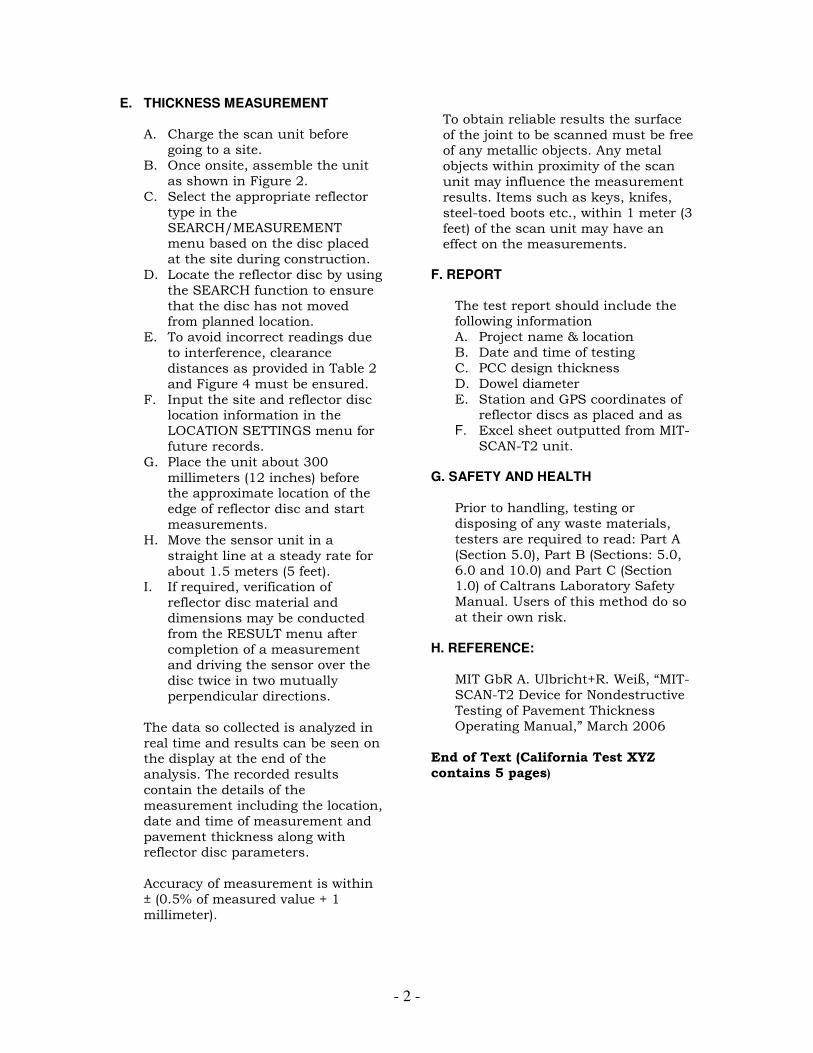
E. THICKNESS MEASUREMENT
A. Charge the scan unit before going to a site.
B. Once onsite, assemble the unit as shown in Figure 2.
C. Select the appropriate reflector type in the SEARCH/MEASUREMENT menu based on the disc placed at the site during construction.
D. Locate the reflector disc by using the SEARCH function to ensure that the disc has not moved from planned location.
E. To avoid incorrect readings due to interference, clearance distances as provided in Table 2 and Figure 4 must be ensured.
F. Input the site and reflector disc location information in the LOCATION SETTINGS menu for future records.
G. Place the unit about 300 millimeters (12 inches) before the approximate location of the edge of reflector disc and start measurements.
H. Move the sensor unit in a straight line at a steady rate for about 1.5 meters (5 feet).
I. If required, verification of reflector disc material and dimensions may be conducted from the RESULT menu after completion of a measurement and driving the sensor over the disc twice in two mutually perpendicular directions.
The data so collected is analyzed in real time and results can be seen on the display at the end of the analysis. The recorded results contain the details of the measurement including the location, date and time of measurement and pavement thickness along with reflector disc parameters. Accuracy of measurement is within ± (0.5% of measured value + 1 millimeter).
To obtain reliable results the surface of the joint to be scanned must be free of any metallic objects. Any metal objects within proximity of the scan unit may influence the measurement results. Items such as keys, knifes, steel-toed boots etc., within 1 meter (3 feet) of the scan unit may have an effect on the measurements.
F. REPORT
The test report should include the following information A. Project name & location B. Date and time of testing C. PCC design thickness D. Dowel diameter E. Station and GPS coordinates of
reflector discs as placed and as F. Excel sheet outputted from MIT-
SCAN-T2 unit.
G. SAFETY AND HEALTH Prior to handling, testing or disposing of any waste materials, testers are required to read: Part A (Section 5.0), Part B (Sections: 5.0, 6.0 and 10.0) and Part C (Section 1.0) of Caltrans Laboratory Safety Manual. Users of this method do so at their own risk.
H. REFERENCE:
MIT GbR A. Ulbricht+R. Weiß, “MIT-SCAN-T2 Device for Nondestructive Testing of Pavement Thickness Operating Manual,” March 2006
End of Text (California Test XYZ contains 5 pages)

- 3 -
Table 1. Disc selection guide
Design Pavement Thickness Disc Diameter
0 to 180 mm (0 to 7.1 in) 70 mm (2.7 in)
181 to 450 mm (7.1 to 17.7 in) 300 mm (11.8 in)
Table 2. Clearance distances for operation of MIT-SCAN-T2 sensor unit
Interference type Minimum clearance from sensor unit
Parked cars 2 m (6.6 ft)
Moving traffic 1 m (3.3 ft)
Other reflector discs 0.5 m (1.7 ft)
Construction equipment 4 m (13 ft)
Guardrails and other safety features 1 m (3.3 ft)
Figure 1. MIT-SCAN-T2 system disassembled for storage

- 4 -
Figure 2. Assembled MIT-SCAN-T2 system

- 5 -
Figure 3. Steel reflector discs of 70 mm and 300 mm diameter
Figure 4. Clearance zones required during measurement
Reflector disc
0.5 m (1.7 ft) Other reflector discs, keys, coins, etc.
1 m (3.3 ft) Moving traffic, safety features
2 m (6.6 ft) Parked cars
4 m (6.6 ft) Construction equipment, heavy machinery