Method Statement Esprit Control Equipment - Pole …myelectricavenue.info/sites/default/files/Esprit...
37
Method Statement Esprit Control Equipment - Pole Mounted HV/LV Prepared for: SSEPD Project No: 86000 Document Version: 3.1 Date: 06 July 2015
Transcript of Method Statement Esprit Control Equipment - Pole …myelectricavenue.info/sites/default/files/Esprit...

Method Statement Esprit Control
Equipment - Pole Mounted HV/LV
Transformer Structures
Prepared for: SSEPD
Project No: 86000
Document Version: 3.1
Date: 06 July 2015

Private and confidential
Method Statement Esprit Control Equipment - Pole Mounted HV/LV Transformer Structures
86000 - 3.1
CONFIDENTIAL - This document may not be disclosed to any person other than the addressee or any duly authorised person
within the addressee's company or organisation and may only be disclosed so far as is strictly necessary for the proper
purposes of the addressee which may be limited by contract. Any person to whom the document or any part of it is disclosed
must comply with this notice. A failure to comply with it may result in loss or damage to EA Technology Ltd or to others with
whom it may have contracted and the addressee will be held fully liable therefor.
Care has been taken in the preparation of this Report, but all advice, analysis, calculations, information, forecasts and
recommendations are supplied for the assistance of the relevant client and are not to be relied on as authoritative or as in
substitution for the exercise of judgement by that client or any other reader. EA Technology Ltd. nor any of its personnel
engaged in the preparation of this Report shall have any liability whatsoever for any direct or consequential loss arising from
use of this Report or its contents and give no warranty or representation (express or implied) as to the quality or fitness for
the purpose of any process, material, product or system referred to in the report.
All rights reserved. No part of this publication may be reproduced or transmitted in any form or by any means electronic,
mechanical, photocopied, recorded or otherwise, or stored in any retrieval system of any nature without the written
permission of the copyright holder.
© EA Technology Ltd July 2015
EA Technology Limited, Capenhurst Technology Park, Capenhurst, Chester, CH1 6ES;
Tel: 0151 339 4181 Fax: 0151 347 2404
http://www.eatechnology.com
Registered in England number 2566313
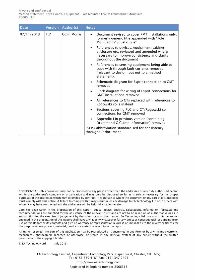
Version History
Date Version Author(s) Notes
24/04/2013 1.6 Alex Halavin Version sent to SSE. Based on previous documents
provided by SSE.
29/07/2013 1.6.1 Mary Gillie Modifications after meeting with SSE
“Order of installation” inserted as new section 5
Sections 4.1 On-site installation works, 4.2
Detailed Physical Inspection renumbered sections
6 and 5 respectively. Section 5 Equipment
Installation to Section 8 etc.
Schematic diagram for Esprit connection to GMT
utilising MCCB and RCD removed
Recommendations re: access requirements
between Esprit monitor controller and GMT or
PMT rationalised
Requirement to ensure appropriate shielding of
terminals in LV Pillars inserted
CT and Rogowski Coils – warning added re:
installation of Esprit and associated connections
not to introduce additional hazard or interfere
with general operation
Commissioning: “Esprit equipment fitted” advice
label content – “Instructions in case of the unit
failing” requirement inserted
Minor amendments and clarifications to installation
instructions for PLC and CT or Rogowski Coils re:
routing and terminations
Private and confidential
Method Statement Esprit Control Equipment - Pole Mounted HV/LV Transformer Structures
86000 - 3.1
CONFIDENTIAL - This document may not be disclosed to any person other than the addressee or any duly authorised person
within the addressee's company or organisation and may only be disclosed so far as is strictly necessary for the proper
purposes of the addressee which may be limited by contract. Any person to whom the document or any part of it is disclosed
must comply with this notice. A failure to comply with it may result in loss or damage to EA Technology Ltd or to others with
whom it may have contracted and the addressee will be held fully liable therefor.
Care has been taken in the preparation of this Report, but all advice, analysis, calculations, information, forecasts and
recommendations are supplied for the assistance of the relevant client and are not to be relied on as authoritative or as in
substitution for the exercise of judgement by that client or any other reader. EA Technology Ltd. nor any of its personnel
engaged in the preparation of this Report shall have any liability whatsoever for any direct or consequential loss arising from
use of this Report or its contents and give no warranty or representation (express or implied) as to the quality or fitness for
the purpose of any process, material, product or system referred to in the report.
All rights reserved. No part of this publication may be reproduced or transmitted in any form or by any means electronic,
mechanical, photocopied, recorded or otherwise, or stored in any retrieval system of any nature without the written
permission of the copyright holder.
© EA Technology Ltd July 2015
EA Technology Limited, Capenhurst Technology Park, Capenhurst, Chester, CH1 6ES;
Tel: 0151 339 4181 Fax: 0151 347 2404
http://www.eatechnology.com
Registered in England number 2566313
Date Version Author(s) Notes
07/11/2013 1.7 Colin Morris Document revised to cover PMT installations only,
formerly generic title appended with “Pole
Mounted LV Substations”
References to devices, equipment, cabinet,
enclosure etc. reviewed and amended where
necessary to improve consistency and clarity
throughout the document
References to sensing equipment being able to
cope with through fault currents removed
(relevant to design, but not to a method
statement).
Schematic diagram for Esprit connection to GMT
removed
Block diagram for wiring of Esprit connections for
GMT installations removed
All references to CTs replaced with references to
Rogowski coils instead
Sections covering PLC and CT/Rogowski coil
connections for GMT removed
Appendix I in previous version (containing
Drummond G Clamp information) removed
SSEPD abbreviation standardised for consistency
throughout document
Private and confidential
Method Statement Esprit Control Equipment - Pole Mounted HV/LV Transformer Structures
86000 - 3.1
CONFIDENTIAL - This document may not be disclosed to any person other than the addressee or any duly authorised person
within the addressee's company or organisation and may only be disclosed so far as is strictly necessary for the proper
purposes of the addressee which may be limited by contract. Any person to whom the document or any part of it is disclosed
must comply with this notice. A failure to comply with it may result in loss or damage to EA Technology Ltd or to others with
whom it may have contracted and the addressee will be held fully liable therefor.
Care has been taken in the preparation of this Report, but all advice, analysis, calculations, information, forecasts and
recommendations are supplied for the assistance of the relevant client and are not to be relied on as authoritative or as in
substitution for the exercise of judgement by that client or any other reader. EA Technology Ltd. nor any of its personnel
engaged in the preparation of this Report shall have any liability whatsoever for any direct or consequential loss arising from
use of this Report or its contents and give no warranty or representation (express or implied) as to the quality or fitness for
the purpose of any process, material, product or system referred to in the report.
All rights reserved. No part of this publication may be reproduced or transmitted in any form or by any means electronic,
mechanical, photocopied, recorded or otherwise, or stored in any retrieval system of any nature without the written
permission of the copyright holder.
© EA Technology Ltd July 2015
EA Technology Limited, Capenhurst Technology Park, Capenhurst, Chester, CH1 6ES;
Tel: 0151 339 4181 Fax: 0151 347 2404
http://www.eatechnology.com
Registered in England number 2566313
Date Version Author(s) Notes
25/11/13 1.9 Colin Morris Reference to earth connection for the [doubly insulated cabinet (Esprit + Envoy)] expanded and exemption for plastic cabinet added
Appendix II picture and diagram replaced with current versions from Esprit Installation Guide (MC) Issue 5
Modified to reflect SSE / EATL teleconference discussion on 04/11/13. o Requirement for PMT locations to be surveyed
before works proceed added o Neutral earth requirements for variants PMT,
non-PMT pole added inserted o Esprit cabinet alternative pole mounting
location requirements added o Voltage / PLC connections for variants PMT
pole, non-PMT pole inserted o Requirement for fused leads to be used added
into main text o Current sensor fitment and securing and
constraint requirements added
List of SSE document references specific to PMT
installation added
27/11/13 2.0 Mary Gillie Review version
18/12/13 2.1 Mary Gillie review in light of information from Lyndhurst
Appendix II “Typical arrangements for a PMT”
added
08/01/2014 2.2 Colin Morris Based on Gideon Evans’ review of v2.0 and
including changes from v2.0 to v2.1
13/01/2014 2.3 Mary Gillie Reviewed changes
02/04/2014 2.4 Mary Gillie Alterations made after discussions at New Forest
Depot. Including use of a commando socket and
mounting to arrangement to pole.
Private and confidential
Method Statement Esprit Control Equipment - Pole Mounted HV/LV Transformer Structures
86000 - 3.1
CONFIDENTIAL - This document may not be disclosed to any person other than the addressee or any duly authorised person
within the addressee's company or organisation and may only be disclosed so far as is strictly necessary for the proper
purposes of the addressee which may be limited by contract. Any person to whom the document or any part of it is disclosed
must comply with this notice. A failure to comply with it may result in loss or damage to EA Technology Ltd or to others with
whom it may have contracted and the addressee will be held fully liable therefor.
Care has been taken in the preparation of this Report, but all advice, analysis, calculations, information, forecasts and
recommendations are supplied for the assistance of the relevant client and are not to be relied on as authoritative or as in
substitution for the exercise of judgement by that client or any other reader. EA Technology Ltd. nor any of its personnel
engaged in the preparation of this Report shall have any liability whatsoever for any direct or consequential loss arising from
use of this Report or its contents and give no warranty or representation (express or implied) as to the quality or fitness for
the purpose of any process, material, product or system referred to in the report.
All rights reserved. No part of this publication may be reproduced or transmitted in any form or by any means electronic,
mechanical, photocopied, recorded or otherwise, or stored in any retrieval system of any nature without the written
permission of the copyright holder.
© EA Technology Ltd July 2015
EA Technology Limited, Capenhurst Technology Park, Capenhurst, Chester, CH1 6ES;
Tel: 0151 339 4181 Fax: 0151 347 2404
http://www.eatechnology.com
Registered in England number 2566313
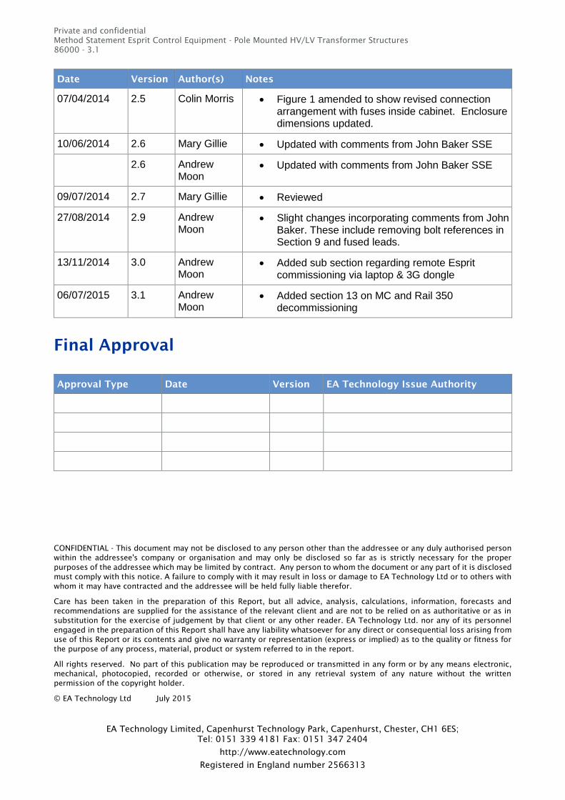
Date Version Author(s) Notes
07/04/2014 2.5 Colin Morris Figure 1 amended to show revised connection arrangement with fuses inside cabinet. Enclosure dimensions updated.
10/06/2014 2.6 Mary Gillie Updated with comments from John Baker SSE
2.6 Andrew Moon
Updated with comments from John Baker SSE
09/07/2014 2.7 Mary Gillie Reviewed
27/08/2014 2.9 Andrew Moon
Slight changes incorporating comments from John Baker. These include removing bolt references in Section 9 and fused leads.
13/11/2014 3.0 Andrew Moon
Added sub section regarding remote Esprit commissioning via laptop & 3G dongle
06/07/2015 3.1 Andrew Moon
Added section 13 on MC and Rail 350 decommissioning
Final Approval
Approval Type Date Version EA Technology Issue Authority

Private and confidential
Method Statement Esprit Control Equipment - Pole Mounted HV/LV Transformer Structures
86000 - 3.1
P:\Projects\Project Numbers 86000 - 86990\04 Working\04 Tier 2 Project\04 Cluster Installation\02 Installation
Documents\01 Method Statements\02 - MC\Esprit Installation Method Statement 3.1.5 PMT.docx
01 July 2015 Page v
Contents
Version History .............................................................................................................................................................................. i
Final Approval .............................................................................................................................................................................. iv
Contents ........................................................................................................................................................................................... v
1. Background ...................................................................................................................................................................... 7
2. Introduction ..................................................................................................................................................................... 7
3. Management of safety ............................................................................................................................................... 8
4. Installation ....................................................................................................................................................................... 9
4.1 First installation – Lyndhurst ............................................................................................ 9
4.2 General requirements for installation .............................................................................. 9
4.3 Order of installation ........................................................................................................ 10
4.4 Detailed visual inspection ............................................................................................... 10
4.5 On-site civil installation works ........................................................................................ 12
4.6 Mounting the cabinet ...................................................................................................... 13
4.7 Installation of Rogowski coils ......................................................................................... 13 4.7.1 Rogowski coils installation instruction at the PMT............................................ 13
4.8 PLC injection point, Esprit power supply installation ................................................... 13 4.8.1 PLC injection point, Esprit power supply (general) ........................................... 13
4.9 Voltage connections installation at a PMT - Specific ..................................................... 16 4.9.1 Installation on PMT pole ...................................................................................... 16 4.9.2 Installation one span out ..................................................................................... 16 4.9.3 Site specific bespoke design ............................................................................... 16 4.9.4 Voltage connections –PMT pole .......................................................................... 16 4.9.5 Voltage connections – one span out .................................................................. 16 4.9.6 Fused leads ........................................................................................................... 17
4.10 Completion ....................................................................................................................... 17
5. Commissioning ........................................................................................................................................................... 18
5.1 Remote commissioning ................................................................................................... 18
6. Decommissioning of the Esprit equipment ............................................................................................... 19
6.1 General requirements for removal ................................................................................. 19
6.2 Decommissioning ............................................................................................................ 19
6.3 Order of removal.............................................................................................................. 20
6.4 Removal of PLC injection points ..................................................................................... 20
6.5 Removal of Rogowski Coils ............................................................................................. 22
6.6 Removal of monitor controller and Rail350 enclosures ............................................... 23 Step 1 – Disconnection of Enclosure Leads Connected to the SIPCs ........................... 23 Step 2 – Disconnection and removal of the Rail350 power supply and modbus
cables .................................................................................................................... 24 Step 3 – Disconnection of the Rail 350 RC cables......................................................... 25 Step 4 – Removal of MC enclosure and Rail350 units from mounting positions ....... 26
6.7 Removal of cable routes and ducting ............................................................................. 27

Private and confidential
Method Statement Esprit Control Equipment - Pole Mounted HV/LV Transformer Structures
86000 - 3.1
P:\Projects\Project Numbers 86000 - 86990\04 Working\04 Tier 2 Project\04 Cluster Installation\02 Installation
Documents\01 Method Statements\02 - MC\Esprit Installation Method Statement 3.1.5 PMT.docx
01 July 2015 Page vi
6.8 Site Inspection .................................................................................................................. 27
Appendix I Esprit Monitor Controller ...................................................................................................................... 29
Our Expertise .............................................................................................................................................................................. 36
Private and confidential
Method Statement Esprit Control Equipment - Pole Mounted HV/LV Transformer Structures
86000 - 3.1
P:\Projects\Project Numbers 86000 - 86990\04 Working\04 Tier 2 Project\04 Cluster Installation\02 Installation
Documents\01 Method Statements\02 - MC\Esprit Installation Method Statement 3.1.5 PMT.docx
01 July 2015 Page 7 of 37
1. Background
This method statement, which responds to the requirements set out by Scottish and Southern Energy
Power Distribution (SSEPD) and EA Technology Limited, has been prepared by EA Technology
Limited, to provide the instructions that should be followed in order to connect Esprit control and
monitoring equipment at pole mounted HV/LV substations.
The latest update to version 3.1 incorporates section 6, “Decommissioning of the Esprit equipment”
into this method statement, providing instructions that should be followed in order to decommission
the Esprit control and monitoring equipment has been included.
2. Introduction
This method statement defines the principles that should be followed in order to connect Esprit
equipment1
.
All equipment should be installed DEAD when possible and LIVE only when it is safe to do so and if
justified by a written risk assessment.
Where it is possible to install this type of equipment DEAD, whilst maintaining supplies to customers
connected to the network to be controlled, this option must be taken. However, it is recognised that
in many cases it will be impractical to make the distribution transformer, the LV pillar or cabinet
DEAD and therefore the guidance within this work instruction must be followed. In order to minimise
time working on a LIVE system, Esprit equipment connection to the energised part of the network
should be carried out last.
Where appropriate, instruction for the installation of equipment will be specific to the chosen
location. The following generic instructions regarding installation will generally apply
1
For the purposes of this document, relating to the installation of the equipment on the trial networks of the My Electric
Avenue project, the Esprit equipment comprises the cabinet containing the EA technology Esprit Monitor Controller along
with a Nortech Envoy mini RTU, the external connections for load monitoring, supply and plc injection plus the Rail 350 unit
and associated connection equipment.

Private and confidential
Method Statement Esprit Control Equipment - Pole Mounted HV/LV Transformer Structures
86000 - 3.1
P:\Projects\Project Numbers 86000 - 86990\04 Working\04 Tier 2 Project\04 Cluster Installation\02 Installation
Documents\01 Method Statements\02 - MC\Esprit Installation Method Statement 3.1.5 PMT.docx
01 July 2015 Page 8 of 37
3. Management of safety
The following requirements will be complied with at all times throughout the installation process.
1. Safety rules and other procedures must be followed whilst undertaking work in accordance
with this work instruction. The following documents are particularly relevant and must be
adhered to at all times:
a. Safety precautions and procedures applicable to low voltage systems as detailed in
section 8 of the Operational Safety rules.
b. When work is to be undertaken in proximity to live LV conductors it is necessary to justify
this decision. A risk assessment complying with PR-PS-421, Justification for Live Low
Voltage Working is therefore required.
2. Prior to commencing work a full assessment of risk will be undertaken in accordance with
SSE (or relevant DNO) Injury Prevention Process. This will include a stage one assessment in
advance of work commencing and a stage two on site assessment which shall be undertaken
prior to work commencing. This assessment must be agreed by all members of the working
party and signed off accordingly.
3. The working party will consist of at least two persons who will be appropriately authorised
to undertake the proposed installation work in accordance with SSE (or relevant DNO)
Operational Safety Rules.
4. System control will be advised prior to work starting and upon completion of the work.
5. Personal Protective Equipment will be worn in accordance with SSE PPE matrix (see S&E
Manual Section 1, Appendix 1 of WI-HSE-001) or relevant DNO PPE policy and safety
procedures.
6. The following reference documents are also relevant for pole mounted installations:
SP-PS-140: Specification for conductor fittings and associated apparatus for use with
LV aerial bundled conductor
TG-PS-569: ABC tension and non-tension fittings, lugs, end caps, main joints and
cable connections
PR-PS-045: Procedure for Safe Access to wood Poles
PR-PS-431: Procedure for Live Working on Low Voltage Overhead Networks
TG-PS-529: Conductors to be used on Pole Mounted Transformers - LV connections

Private and confidential
Method Statement Esprit Control Equipment - Pole Mounted HV/LV Transformer Structures
86000 - 3.1
P:\Projects\Project Numbers 86000 - 86990\04 Working\04 Tier 2 Project\04 Cluster Installation\02 Installation
Documents\01 Method Statements\02 - MC\Esprit Installation Method Statement 3.1.5 PMT.docx
01 July 2015 Page 9 of 37
4. Installation
4.1 First installation – Lyndhurst
This method statement is for installation of the Esprit technology that is under development. The
method statement is written to encompass the majority of arrangements of Pole Mounted
Transformers (PMTs). However, the PMT where the Esprit will be installed is sited at Lyndhurst.
The characteristics of the PMT are:
One set of fuses leading to 3 spurs.
The PMT is mounted on robust H pole but there are overhanging trees.
The 3 spurs separate from a pole approximately 4 metres from the transformer H pole.
The conductors are ABC and require cable piercing.
4.2 General requirements for installation
This method statement provides details regarding how to install Esprit equipment safely on pole
mounted transformer structures. It focuses on the methods to be followed in order to make the
necessary current connections and Power Line Communication (PLC) injection points. The PLC
injection points also provide the source of power supply for the Esprit control electronics, and for
any data logging / monitoring equipment as necessary. This method statement provides guidance
regarding the suitable positioning and fixing of Esprit equipment for LV overhead line and PMT
installations.
The below installation instructions shall be followed. Some site specific modifications may be
required.
1.1. Esprit equipment, specifically the Esprit monitor controller, will always be installed in
accordance with manufacturer’s instructions (See I2
EV Esprit Monitor Controller Installation
Guide). It will be contained in its own enclosure comprising of a doubly insulated cabinet
with a non-conducting exterior, no external metallic frame, and typical dimensions of 750h
x 550w x 300d which will also enclose the Envoy communications unit. Specific upstream
system communication requirements are not covered within this method statement. This is
referred to as the [doubly insulated cabinet (Esprit + Envoy)]
1.2. Current References – All 3 phase (no neutral) current values will be obtained by using
approved fully insulated sensing transducers (Rogowski coils). The sensors will be installed
around the cable connections at suitable locations as close as practically possible to the
[doubly insulated cabinet (Esprit + Envoy)]. All equipment used must have the necessary
approvals.
1.3. Where a generic installation instruction is to be followed, a full assessment of options for
the connection of current sensors will be made prior to any work commencing.
1.4. Prior to work commencing, a visual inspection of the connection points will be carried out
with particular attention being made to positions where current sensors and PLC injection
connections are to be installed. If there is any doubt regarding the condition of the
connection point, work shall not commence and the issue shall be referred to the person
responsible for instructing the installation.
1.5. In particular, all PMT installations require a survey before works proceed to identify:
Location of the HV and LV earths.
Private and confidential
Method Statement Esprit Control Equipment - Pole Mounted HV/LV Transformer Structures
86000 - 3.1
P:\Projects\Project Numbers 86000 - 86990\04 Working\04 Tier 2 Project\04 Cluster Installation\02 Installation
Documents\01 Method Statements\02 - MC\Esprit Installation Method Statement 3.1.5 PMT.docx
01 July 2015 Page 10 of 37
Type of conductor / insulation on outgoing side of fuse
Routing and connectivity of mains and services
Safe access to pole and pole working (safety clearances)
Consents - pole mounting is not contentious, but access to poles is subject to the terms
and conditions agreed in the respective wayleaves and easements; in all cases the
landowner should be informed prior to the start of work.
Agreement for any tree cutting required.
4.3 Order of installation
The exact arrangements for installation will depend on the site. A site survey will be required in
each case to finalise arrangements. The order of installation and connections will be the same in
each case:
1. Detailed visual Inspection
2. Any civil work required
3. Connection of Rogowski coils
4. PLC injection/power supply
These are described in detail in the Sections 4.4 to 4.9.
4.4 Detailed visual inspection
In addition to the requirements detailed in Sections 0 (

Private and confidential
Method Statement Esprit Control Equipment - Pole Mounted HV/LV Transformer Structures
86000 - 3.1
P:\Projects\Project Numbers 86000 - 86990\04 Working\04 Tier 2 Project\04 Cluster Installation\02 Installation
Documents\01 Method Statements\02 - MC\Esprit Installation Method Statement 3.1.5 PMT.docx
01 July 2015 Page 11 of 37
Management of safety) and 4.2 (General requirements for installation) a visual inspection shall be
carried out:
1. A detailed visual inspection shall include:
All parts of the [Eldon (Esprit + Envoy) cabinet] or other point of measurement / supply
including checks for damage to insulation, overheating (present and historic).
Overhead lines and connection methods; this shall include the inspection of all assets to
identify any damage/ breakdown of insulation and overheating issues. Identify any need
for tree cutting or other clearing.
Inspection of abnormal connections.
2. Where an unsafe situation is identified, all work on site will cease and appropriate repairs
will be instigated. No Esprit equipment will be installed until repairs have been completed
and any unsafe situation has been rectified.
3. Wherever possible the [doubly insulated cabinet (Esprit + Envoy)] will be fixed in its
permanent position before installation of the associated connections commences.
Care should be taken to ensure that any equipment installed will not interfere with or prevent the
safe operation of any equipment located in the substation and the possibility of damage to the
insulation is minimised.

Private and confidential
Method Statement Esprit Control Equipment - Pole Mounted HV/LV Transformer Structures
86000 - 3.1
P:\Projects\Project Numbers 86000 - 86990\04 Working\04 Tier 2 Project\04 Cluster Installation\02 Installation
Documents\01 Method Statements\02 - MC\Esprit Installation Method Statement 3.1.5 PMT.docx
01 July 2015 Page 12 of 37
4.5 On-site civil installation works
If there is sufficient clearance to the High Voltage Equipment (as in Lyndhurst), the HV will be live
otherwise it must be made dead. Installers will be working under SSEPD safety instructions.
1. Carry out tree cutting or other clearing if access to the pole is not clear.
2. Check the equipment labelling that the equipment: ([doubly insulated cabinet (Esprit +
Envoy)], Rogowski coils, PLC connections are of suitable for the proposed location.
3. For PMT poles, the [doubly insulated cabinet (Esprit + Envoy)] should be mounted above the
anti-climb guard (ACG), preferably on the opposite side of the pole to the fusegear. In
practice, the position will be determined by available pole space avoiding existing equipment
and conductors.
4. For non PMT poles, the [doubly insulated cabinet (Esprit + Envoy)] should be mounted high
enough to ensure it is not readily accessible to third parties, but low enough to be 1.5m clear
of live conductors and equipment. Ideally the cabinet should be accessible for software
modifications via a step ladder without working on the top two steps. However this may not
always be possible whilst maintaining safe heights and clearances.
5. A clearly visible "danger of death" sign should be fitted to the cabinet if not already present
on the pole the cabinet is to be mounted on.
6. ACDs shall be installed generally in accordance with ENA TS 43-90, where there is a
probability of climbing access using the installed equipment.
The [doubly insulated cabinet (Esprit + Envoy)] will be attached to the pole using suitable clamps
that allow for the passage of any cabling down the pole without crimping or crushing. To avoid the
risk of connecting the LV and HV earth, the [doubly insulated cabinet (Esprit + Envoy)] should be
mounted to brackets that do not allow the mounting steelwork to be in a position where it can make
direct contact with the HV steelwork or earth. This can be achieved by using either a stainless steel
bracket coated in 3.4 mm cross linked Polyethylene (XLPE) or a stainless steel bracket with 3.4mm
Nylon bushings in the boltholes for the 10mm supporting coach bolts. This thickness of electrical
insulation is designed to withstand a voltage of 5 kV. This bracket specification shall be termed
‘suitably insulated’ for the remainder of the document.
Care must be taken to ensure that installation of Esprit equipment and associated connections does
not introduce additional hazards or interfere with the general operational requirements of the PMT.
Where necessary cable ties and suitable flexible conduits should be used to ensure a tidy installation
is achieved with sufficient protection against accidental damage.

Private and confidential
Method Statement Esprit Control Equipment - Pole Mounted HV/LV Transformer Structures
86000 - 3.1
P:\Projects\Project Numbers 86000 - 86990\04 Working\04 Tier 2 Project\04 Cluster Installation\02 Installation
Documents\01 Method Statements\02 - MC\Esprit Installation Method Statement 3.1.5 PMT.docx
01 July 2015 Page 13 of 37
4.6 Mounting the cabinet
The cabinet will be provided with a suitably insulated bracket that can be fixed to the pole by 10mm
diameter coach screws at the top and bottom. The coach screws should be 75mm long, as they will
avoid the need to drill through the pole which may introduce risks to the PMT equipment and cables.
1. Mark points where bolts will be inserted into the pole.
2. Drill holes for bolts.
3. Use ‘coach screws’ penetrating right through the pole.
4. Hang cabinet on bolts and secure.
4.7 Installation of Rogowski coils
There is no set arrangement for connection of the Rogowski coils and therefore great caution should
be taken during their installation. The proposed method is described below.
4.7.1 Rogowski coils installation instruction at the PMT
1. Install 3 current sensors (one per phase).
2. Highlight the cables and conductors that require to be monitored as per the written work
instruction.
3. For non PMT pole installations, current sensors may be harder to fit on ABC if the cores have
not already been spread out. These conductors may be under tension - seek advice as to test
and demonstrate the spreading of conductors under tension for the purpose of fitting
Rogowski coils to write a method statement for this process. Note that the cables at
Lyndhurst are already spread on the pole adjacent to the H pole carrying the transformer and
therefore this process is not document here.
4. Starting with the nearest or furthest cable, install and secure the coil / transducer in position
making sure that the arrows on the coil are pointing in the direction that the load is flowing
as per the manufacturer’s instructions. Install the remaining coils / transducers working from
the back towards the front.
5. Once installed, position all coil / transducer cables in their final location – in line with
manufacturer’s instructions.
6. Current sensors should be constrained from moving in the wind (vibration will cause wear,
noise etc.).
7. Current sensor connecting leads to be tagged (for identification at the end to be connected
to the Esprit, before tying together) to limit movement, and are to be made to look neat, and
routed to avoid interfering with existing fuse gear. Where possible, cable guards will be used
to protect all of the leads.
4.8 PLC injection point, Esprit power supply installation
Reminder - This is a Live Network, appropriate PPE must be worn at all times and only approved
insulated tools shall be used, as defined in SSE’s safety policies for working on LV overhead
lines.
4.8.1 PLC injection point, Esprit power supply (general)
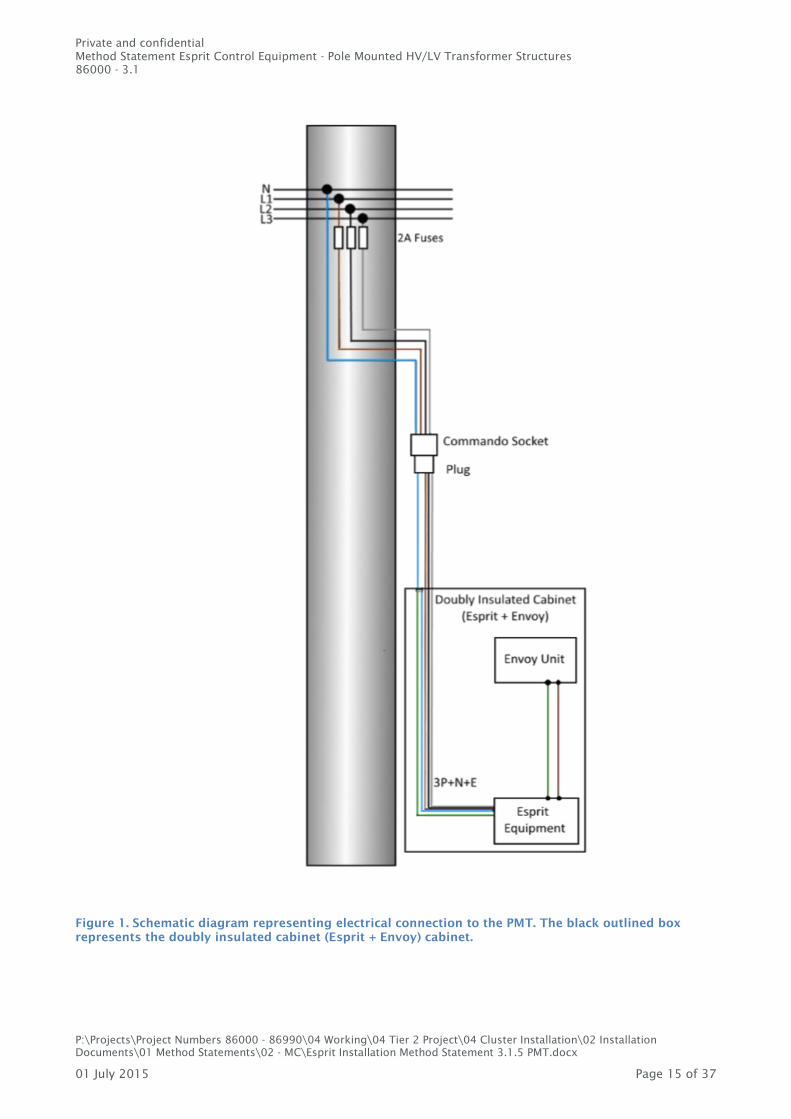
The Esprit monitor controller power supply and PLC injection points are combined (Figure 1). For
pole mounted installations, cable piercing or bare wire connectors will be required for PLC injection
and the Esprit power supply. In all cases, the connecting leads will be connection to an IP 67 rated

Private and confidential
Method Statement Esprit Control Equipment - Pole Mounted HV/LV Transformer Structures
86000 - 3.1
P:\Projects\Project Numbers 86000 - 86990\04 Working\04 Tier 2 Project\04 Cluster Installation\02 Installation
Documents\01 Method Statements\02 - MC\Esprit Installation Method Statement 3.1.5 PMT.docx
01 July 2015 Page 14 of 37
‘commando socket’ fused with a 2A fuse to prevent any failure of the new equipment affecting
existing supplies.
The Esprit control equipment requires PLC injection points; one per phase and neutral (3P+N)
connection.
The connections to the 3 phases and neutral provide the power supply and earthing. Therefore the
connection method used should be suitable approved permanent connections.
The lead will be connected to one side of a commando socket. Connect the bare ends to IPC
connectors (or other suitable connection equipment. Note that the joint made may need to be
packed given that the leads will be 4mm or smaller.
Voltage connections should only be made once all other ends of each cable have been made off and
shrouded to prevent accidental contact with staff or conductors. The commando socket will have a
suitable shroud.
Where necessary cable ties and suitable flexible conduits should be used to ensure a tidy installation
is achieved with sufficient protection against accidental damage. Where possible a cable guard will
be used to protect all leads.
Private and confidential
Method Statement Esprit Control Equipment - Pole Mounted HV/LV Transformer Structures
86000 - 3.1
P:\Projects\Project Numbers 86000 - 86990\04 Working\04 Tier 2 Project\04 Cluster Installation\02 Installation
Documents\01 Method Statements\02 - MC\Esprit Installation Method Statement 3.1.5 PMT.docx
01 July 2015 Page 15 of 37
Figure 1. Schematic diagram representing electrical connection to the PMT. The black outlined box
represents the doubly insulated cabinet (Esprit + Envoy) cabinet.

Private and confidential
Method Statement Esprit Control Equipment - Pole Mounted HV/LV Transformer Structures
86000 - 3.1
P:\Projects\Project Numbers 86000 - 86990\04 Working\04 Tier 2 Project\04 Cluster Installation\02 Installation
Documents\01 Method Statements\02 - MC\Esprit Installation Method Statement 3.1.5 PMT.docx
01 July 2015 Page 16 of 37
4.9 Voltage connections installation at a PMT - Specific
Voltage connection should be made on the outgoing side of the fuse gear.
There are three options available for the installation of the voltage connections:
On the PMT pole
On a pole one span out
Site specific bespoke design
4.9.1 Installation on PMT pole
Install the [doubly insulated cabinet (Esprit + Envoy)] on the PMT pole in the following situation,
where
The installation, including access to the neutral conductor, can be made without infringing
the HV clearance.
The pole is robust and stable such that it is safe to install the [doubly insulated cabinet
(Esprit + Envoy)].
4.9.2 Installation one span out
Install the [doubly insulated cabinet (Esprit + Envoy)] one span out in the following situation:
There is only one spur or the total current required for monitoring purposes can be
measured one span from the transformer.
The pole is robust and stable such that it is safe to install the [doubly insulated cabinet
(Esprit + Envoy)].
4.9.3 Site specific bespoke design
In the event that specific site conditions prevent the use of either of the above options, this method
statement is unsuitable to cover the installation works and a site specific bespoke design and
associated method statement will be required.
4.9.4 Voltage connections –PMT pole
For voltage connections adjacent to PMT fuse gear, conductors will either be ABC or conventional
double insulated (Henlite). For the power and PLC connections:
For 50 or 95mm² aluminium aerial bundled conductor, insulated with a single layer of XLPE
or 50,70,95 or 120mm² PVC double insulated aluminium conductor use SSE approved IPC
connectors.
For conventional conductors, stripping the outer insulating layer, then use IPC connectors.
This process is subject to approval and not required at Lyndhurst. This is not an approved
practice in SSEPD and would need to be approved on a case-by-case basis.
In all cases, check that the arrangement is practical for repairs or post project removal.
4.9.5 Voltage connections – one span out
For non PMT pole installations, voltage connections will be made off on ABC or bare conductor. ABC
connections can be fitted using IPC connectors. For bare conductors, pre-existing overhead line

Private and confidential
Method Statement Esprit Control Equipment - Pole Mounted HV/LV Transformer Structures
86000 - 3.1
P:\Projects\Project Numbers 86000 - 86990\04 Working\04 Tier 2 Project\04 Cluster Installation\02 Installation
Documents\01 Method Statements\02 - MC\Esprit Installation Method Statement 3.1.5 PMT.docx
01 July 2015 Page 17 of 37
service components used for service joints should be used (line taps for bare conductor). The use
of line taps will need a special dispensation as SSE do not use them as standard.
4.9.6 Fused leads
Fused leads (4mm) will be used, as indicated in 4.8.1. The fuses will be on the OHL side of the
commando socket. Fuse ratings should not exceed 2 Amps.
Where necessary cable ties and suitable flexible conduits should be used to ensure a tidy installation
is achieved with sufficient protection against accidental damage.
4.10 Completion
Ensure that the Esprit control box is securely fixed in its final location and that all cables are secured
along the length by means of cable ties or ducting with identification tags fitted to all cables.
Ensure that all connections at the Esprit control box and PLC connection sockets are secure.
Fix notice to the pole with information about the equipment and emergency number.
Refer to Section 0 ‘Commissioning’ for the procedure with regard to overall commissioning and
labelling requirements.

Private and confidential
Method Statement Esprit Control Equipment - Pole Mounted HV/LV Transformer Structures
86000 - 3.1
P:\Projects\Project Numbers 86000 - 86990\04 Working\04 Tier 2 Project\04 Cluster Installation\02 Installation
Documents\01 Method Statements\02 - MC\Esprit Installation Method Statement 3.1.5 PMT.docx
01 July 2015 Page 18 of 37
5. Commissioning
Commissioning of the Esprit equipment shall be in accordance with the commissioning method
statement (latest version available from EA Technology Limited)
The installer will ensure that the SSEPD network information systems (GIS) are updated appropriately
to record the installation of the monitoring equipment and any modifications made to the PMT. A
note annotated to the pole (as shown on GIS) to say "Monitoring Fitted" would be helpful to the
majority of users.
A record shall be kept for all aspects of commissioning.
5.1 Remote commissioning
Should the Esprit system require remote commissioning, a 3G connected laptop will be placed within
the MC enclosure and connected to the RS232 port via a serial cable. The serial cable and laptop will
be provided onsite by an EA Technology representative.
When in place, the enclosure door should be shut and secured. Once commissioning via the laptop
has taken place, the laptop must be removed, swapping the serial cable from the laptop with the
serial cable from the envoy unit at the service port shown in Figure 9. Once the MC shows an active
connection via the Nortech website, the MC enclosure door can be shut and secured. An EA
technology representative will confirm this.

Private and confidential
Method Statement Esprit Control Equipment - Pole Mounted HV/LV Transformer Structures
86000 - 3.1
P:\Projects\Project Numbers 86000 - 86990\04 Working\04 Tier 2 Project\04 Cluster Installation\02 Installation
Documents\01 Method Statements\02 - MC\Esprit Installation Method Statement 3.1.5 PMT.docx
01 July 2015 Page 19 of 37
6. Decommissioning of the Esprit equipment
Before reading through this section on decommissioning, persons carrying out the decommissioning
must read and understand Section 0 – The Management of Safety, within this document.
Decommissioning persons must adhere to these safety instructions at all times. The
decommissioning work will require live working and therefore must be carried out by either SSEPD
staff or 3rd
party contractors who are authorised for live working.
Suitable safety gear and insulated tools must be used, these must include:
An Inner layer of live working gloves consisting of insulating material (EN60903 Class 0 or
above)
Over gloves capable of providing mechanical protection (compliant with EN388).
A Class 0 Arc Flash safety helmet with safety shield, compliant with the following standards
o EN397:2012 – Industrial Safety Helmets
o EN50365: 2002 - Electrically insulating helmets for use on low voltage installations
o EN166: 2001 – European Standards and Markings for Eye and Face Protection
Arc Flash Protective Coveralls, compliant with the following standards:
o BS EN ISO 13688:2013 - Protective clothing. General requirements
o EN 61482-1-1 (12.4 Cal/cm²) - Live working. Protective clothing against the thermal
hazards of an electric arc.
o EN 61482-1-2:2007 (Class 1) - Live working. Protective clothing against the thermal
hazards of an electric arc.
o IEC 61482-2- Live working. Protective clothing against the thermal hazards of an
electric arc.
o EN ISO 11612 (A1, A2, B1, C1) - Protective clothing - Clothing to protect against
heat and flame
o EN61482-1-2:2007 - Live working. Protective clothing against the thermal hazards of
an electric arc. Test methods. Determination of arc protection class of material and
clothing by using a constrained and directed arc.
Complete range of insulated tools for live working up to 1 000 Volts according to IEC 60900
standard
Steel toe capped insulating boots compliant with:
o EN 50321 Live working up to 1000 volts AC
o EN345-1 & EN 50321 class 0
Suitable safety equipment for working at height
6.1 General requirements for removal
Prior to work commencing, a visual inspection of the connection points will be carried out, with
particular attention being made to positions where current sensors and Service Insulation Piercing
Connectors (SIPCs) have been installed. If there is any doubt regarding the safe removal of the Esprit
equipment, work shall not commence. The issue shall be referred to the person responsible for
instructing the installation.
6.2 Decommissioning
The substation shall be returned to its original state, prior to the Esprit equipment installation.
The removal contractor or DNO representative will ensure that the SSEPD network information
systems (GIS and PLACAR) are updated appropriately to record the removal of the Esprit control and
any monitoring equipment and all (if any) modifications made to the pole mounting equipment.

Private and confidential
Method Statement Esprit Control Equipment - Pole Mounted HV/LV Transformer Structures
86000 - 3.1
P:\Projects\Project Numbers 86000 - 86990\04 Working\04 Tier 2 Project\04 Cluster Installation\02 Installation
Documents\01 Method Statements\02 - MC\Esprit Installation Method Statement 3.1.5 PMT.docx
01 July 2015 Page 20 of 37
6.3 Order of removal
The exact arrangements for removal will depend on the site. Knowledge of each EV cluster PMT and
LV feeder will be used to finalise arrangements with the relevant stakeholders. The order of
disconnections and equipment removal will be the same in each case:
1. Esprit unit commando plug disconnected from PLC injection points (SIPCs of 3) by the
disconnection of the commando power supply socket
2. Disconnection of Rogowski coils from Esprit enclosure socket
3. Disconnection of Rail 350 monitor power supply cable from Esprit enclosure
4. Disconnection of Rogowski Coils from Rail 350 terminals
5. Removal of Rail 350 and Esprit Brackets and Enclosures
6. Removal PLC injection/power supply connections from SIPCs through to a commando
socket
7. Removal of SIPCs from ABC cables
8. Removal of cable routes and ducting
9. Any required civil restoration works
10. A detailed visual inspection
The work required for each of the steps and the options available are described in the next
subsections.
The order that the cables should be disconnected can be summarised as follows.
1. Disconnect the PLC injection supply cable from the SIPCs by cutting the supply cables
below the IPCs and then apply heat shrink caps to the cable core stubs. This should be
carried out one phase at a time, then the neutral last in line with the pre-existing OH Line
procedure for disconnection of a service.
2. Disconnect the PLC injection/power supply by unplugging the commando plug and socket.
3. Rogowski coils are to be removed, starting with the nearest and ending with the rearmost
from the removal contractors position.
4. Remove protective cable capping from the feeder pole, then remove the PLC
injection/supply leads and RC/CT leads for the Esprit and Rail 350 units. Remove from
cable routes then coil and tie the leads. Do not coil less than the minimum bending radii of
the leads.
5. Remove commando socket from the LV feeder pole and move all coils, power and current
sensor leads away from LV pole and store in a secure and dry environment.
6.4 Removal of PLC injection points
Care must be taken to ensure that the removal of PLC Injection Point equipment and connections
does not introduce additional hazards or interfere with the general operational requirements of the
LV feeder phase conductors and fuses and their operation. The commando plug, connected to the
Esprit equipment, must be disconnected before the SIPCs are removed.
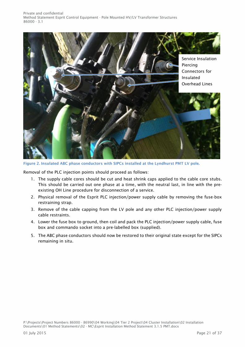
Upon satisfactory inspection and identification of the cable access route, the ABC cable can be
prepared for disconnection of the SIPCs supply cable cores and the Esprit monitor controller power
supply. The removal should begin with the identification of SIPC locations on insulated ABC phase
conductors where the phase, neutral and earth connections have been made off to the MC using the
SIPCs.
Private and confidential
Method Statement Esprit Control Equipment - Pole Mounted HV/LV Transformer Structures
86000 - 3.1
P:\Projects\Project Numbers 86000 - 86990\04 Working\04 Tier 2 Project\04 Cluster Installation\02 Installation
Documents\01 Method Statements\02 - MC\Esprit Installation Method Statement 3.1.5 PMT.docx
01 July 2015 Page 21 of 37
Figure 2. Insulated ABC phase conductors with SIPCs installed at the Lyndhurst PMT LV pole.
Removal of the PLC injection points should proceed as follows:
1. The supply cable cores should be cut and heat shrink caps applied to the cable core stubs.
This should be carried out one phase at a time, with the neutral last, in line with the pre-
existing OH Line procedure for disconnection of a service.
2. Physical removal of the Esprit PLC injection/power supply cable by removing the fuse-box
restraining strap.
3. Remove of the cable capping from the LV pole and any other PLC injection/power supply
cable restraints.
4. Lower the fuse box to ground, then coil and pack the PLC injection/power supply cable, fuse
box and commando socket into a pre-labelled box (supplied).
5. The ABC phase conductors should now be restored to their original state except for the SIPCs
remaining in situ.
Service Insulation
Piercing
Connectors for
Insulated
Overhead Lines
Private and confidential
Method Statement Esprit Control Equipment - Pole Mounted HV/LV Transformer Structures
86000 - 3.1
P:\Projects\Project Numbers 86000 - 86990\04 Working\04 Tier 2 Project\04 Cluster Installation\02 Installation
Documents\01 Method Statements\02 - MC\Esprit Installation Method Statement 3.1.5 PMT.docx
01 July 2015 Page 22 of 37
Figure 3. Insulated ABC phase conductors with SIPCs installed at the Lyndhurst PMT LV pole.
6.5 Removal of Rogowski Coils
Figure 4. Two sets of RCs installed at the Lyndhurst PMT LV pole.
PLC
Injection/Power
supply fuse box
RC set for the
Rail 350
RC set for the
Esprit MC
Private and confidential
Method Statement Esprit Control Equipment - Pole Mounted HV/LV Transformer Structures
86000 - 3.1
P:\Projects\Project Numbers 86000 - 86990\04 Working\04 Tier 2 Project\04 Cluster Installation\02 Installation
Documents\01 Method Statements\02 - MC\Esprit Installation Method Statement 3.1.5 PMT.docx
01 July 2015 Page 23 of 37
There is no set arrangement for the disconnection of the Rogowski coils and therefore great caution
should be taken when removing these devices. Where a Rail 350 unit is present, two sets of RCs will
be installed; one set for the Esprit MC (blue) and one set for the Rail 350 units (green). These are
picture in Figure 4.
Figure 5. MC Rogowski coil retaining clip.
Remove the MC RCs, by squeezing on the retaining clips at the location shown in Figure 5. The Rail
350 RCs can be remove by pulling apart the black plastic socket and plug located on the green coils.
Remove both the RCs for the MC and the RC for the Rail 350 units at the same time. When removing
RCs, take care not to strike any phase conductors when the RC loops separate. LV ABC phase
conductors may only be flexed or moved using very gentle force.
All RC leads running up to the ABC cables, should now be removed. Where necessary, cable ties and
RC cable capping should be unclipped as a last step to ensure a no loose cable poses an
entanglement hazard.
6.6 Removal of monitor controller and Rail350 enclosures
Step 1 – Disconnection of Enclosure Leads Connected to the SIPCs
The Esprit substation equipment should be removed in a de-energised state. Therefore, the Esprit
enclosure commando plug should be disconnected from PLC injection (of 3) through the
disconnection of the commando power supply socket before any removal working commences.
The Esprit Rogowski coils should now be disconnected from the RC socket on the MC enclosure
casing.
Private and confidential
Method Statement Esprit Control Equipment - Pole Mounted HV/LV Transformer Structures
86000 - 3.1
P:\Projects\Project Numbers 86000 - 86990\04 Working\04 Tier 2 Project\04 Cluster Installation\02 Installation
Documents\01 Method Statements\02 - MC\Esprit Installation Method Statement 3.1.5 PMT.docx
01 July 2015 Page 24 of 37
Step 2 – Disconnection and removal of the Rail350 power supply and modbus cables
Figure 6. Power supply terminal box within MC enclosure.
To remove the Esprit enclosure, the Rail 350 monitor power supply cable should be disconnected
from the terminal block (shown in Figure 6), then unclipped from any retaining cable ties and pulled
though the gland in the Enclosure base. The loose Rail 350 monitor power supply cable should be
coiled and taped together, removing any entanglement hazard.
The Rail 350 Modbus cable is to be removed at this stage. This can be achieved by removing the
green terminal block from the envoy unit base and unscrewing the Modbus cable cores from the
terminals, located in the green terminal block. The Modbus cable should then be unclipped from
any restraining ties with the MC enclosure and pulled through the Modbus cable gland, situated on
the MC enclosure base.
Esprit 3PNE
Power Cable
Back Plate
Mounting Screw
Rail 350 Modbus
Cable
Rail 350
3PNE Power
Cable
Esprit 3PNE
Power Cable
Back Plate
Mounting Screw
Rail 350 Modbus
Cable
Rail 350
3PNE Power
Cable
Private and confidential
Method Statement Esprit Control Equipment - Pole Mounted HV/LV Transformer Structures
86000 - 3.1
P:\Projects\Project Numbers 86000 - 86990\04 Working\04 Tier 2 Project\04 Cluster Installation\02 Installation
Documents\01 Method Statements\02 - MC\Esprit Installation Method Statement 3.1.5 PMT.docx
01 July 2015 Page 25 of 37
Figure 7. Esprit MC enclosure base.
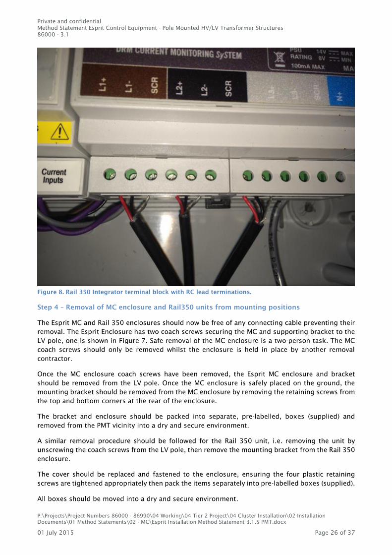
Step 3 – Disconnection of the Rail 350 RC cables
The Rogowki coils for the Rail 350 units, should be disconnected from the Rail 350 RC terminals
during this step. To achieve this, the Rail 350 enclosure cover should be removed by unscrewing the
four plastic retaining screws, which are located below the transparent lid. The cover be should set
aside in a safe place. The RC leads should now be removed from Rail 350 terminal block (pictured
in Figure 8) and pulled though gland situated in the bottom plate of the Rail 350 enclosure. Any
loose RC cable should be made safe, ready for eventual removal from the LV ABC cable. The specific
terminals to be disconnected are L1+, L1 -, L2 + L2 -, L3 +, L3 – and 3 off SCR.
Rail 350 Modbus
gland and cable MC RC cable
plug and socket MC enclosure power
supply cable and gland MC RC cable
plug and socket
Commando plug
and socket
Coach screw
Private and confidential
Method Statement Esprit Control Equipment - Pole Mounted HV/LV Transformer Structures
86000 - 3.1
P:\Projects\Project Numbers 86000 - 86990\04 Working\04 Tier 2 Project\04 Cluster Installation\02 Installation
Documents\01 Method Statements\02 - MC\Esprit Installation Method Statement 3.1.5 PMT.docx
01 July 2015 Page 26 of 37
Figure 8. Rail 350 Integrator terminal block with RC lead terminations.
Step 4 – Removal of MC enclosure and Rail350 units from mounting positions
The Esprit MC and Rail 350 enclosures should now be free of any connecting cable preventing their
removal. The Esprit Enclosure has two coach screws securing the MC and supporting bracket to the
LV pole, one is shown in Figure 7. Safe removal of the MC enclosure is a two-person task. The MC
coach screws should only be removed whilst the enclosure is held in place by another removal
contractor.
Once the MC enclosure coach screws have been removed, the Esprit MC enclosure and bracket
should be removed from the LV pole. Once the MC enclosure is safely placed on the ground, the
mounting bracket should be removed from the MC enclosure by removing the retaining screws from
the top and bottom corners at the rear of the enclosure.
The bracket and enclosure should be packed into separate, pre-labelled, boxes (supplied) and
removed from the PMT vicinity into a dry and secure environment.
A similar removal procedure should be followed for the Rail 350 unit, i.e. removing the unit by
unscrewing the coach screws from the LV pole, then remove the mounting bracket from the Rail 350
enclosure.
The cover should be replaced and fastened to the enclosure, ensuring the four plastic retaining
screws are tightened appropriately then pack the items separately into pre-labelled boxes (supplied).
All boxes should be moved into a dry and secure environment.

Private and confidential
Method Statement Esprit Control Equipment - Pole Mounted HV/LV Transformer Structures
86000 - 3.1
P:\Projects\Project Numbers 86000 - 86990\04 Working\04 Tier 2 Project\04 Cluster Installation\02 Installation
Documents\01 Method Statements\02 - MC\Esprit Installation Method Statement 3.1.5 PMT.docx
01 July 2015 Page 27 of 37
6.7 Removal of cable routes and ducting
At the stage, where the SIPCs and RC leads were secured in place be cable capping and/or cable tied
to the LV pole, all cable routes and cabling should now have been removed. If any Esprit associated
cable restraints or brackets are still present, they should be removed at this stage.
6.8 Site Inspection
In addition to the requirements detailed in Sections 0 (

Private and confidential
Method Statement Esprit Control Equipment - Pole Mounted HV/LV Transformer Structures
86000 - 3.1
P:\Projects\Project Numbers 86000 - 86990\04 Working\04 Tier 2 Project\04 Cluster Installation\02 Installation
Documents\01 Method Statements\02 - MC\Esprit Installation Method Statement 3.1.5 PMT.docx
01 July 2015 Page 28 of 37
Management of safety) and 4.2 (General requirements for installation) a final visual inspection
shall be carried out:
A detailed visual inspection shall include:
The [Eldon (Esprit + Envoy) enclosure] mounting location
The location of cable runs from the [Eldon (Esprit + Envoy) enclosure] to the LV busbar
and
The feeder ABC phase conductors.
Private and confidential
Method Statement Esprit Control Equipment - Pole Mounted HV/LV Transformer Structures
86000 - 3.1
P:\Projects\Project Numbers 86000 - 86990\04 Working\04 Tier 2 Project\04 Cluster Installation\02 Installation
Documents\01 Method Statements\02 - MC\Esprit Installation Method Statement 3.1.5 PMT.docx
01 July 2015 Page 29 of 37
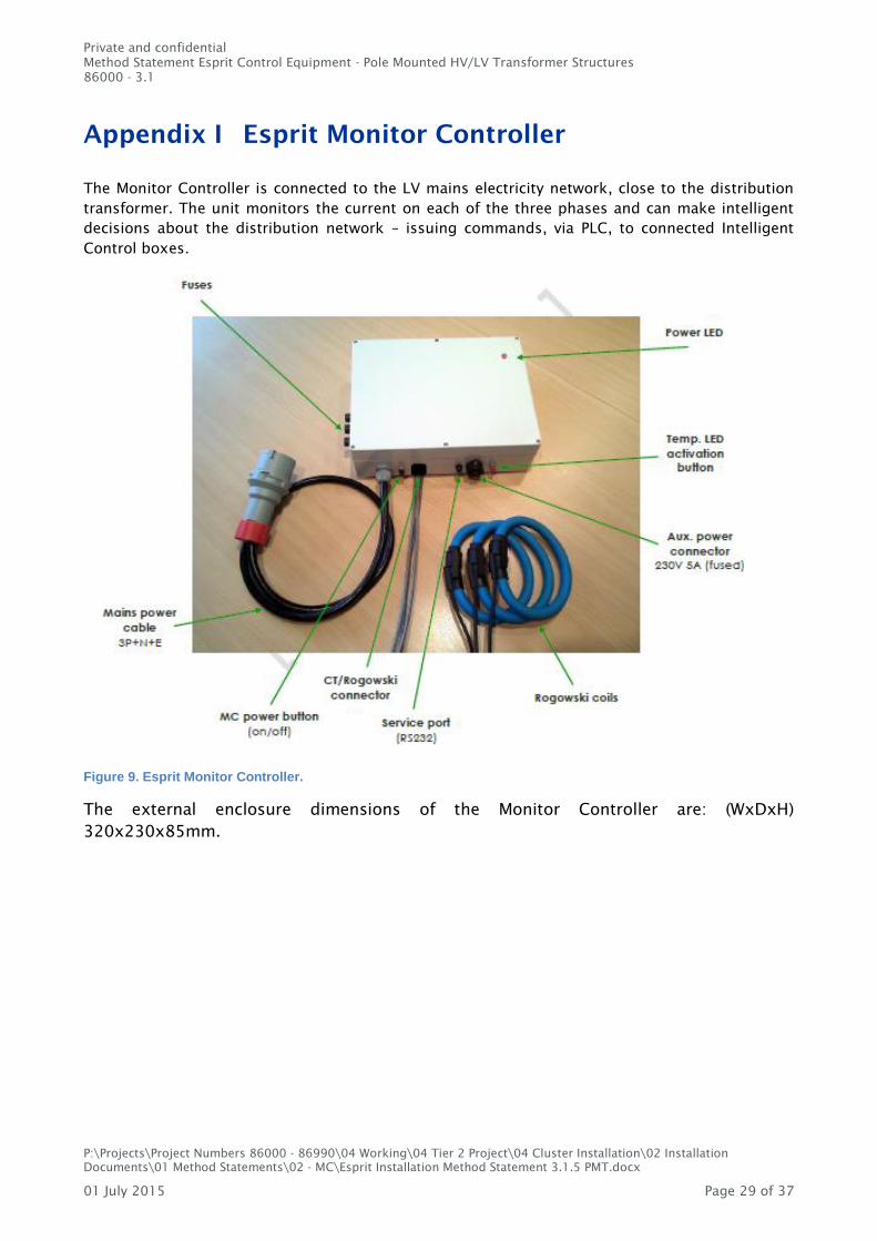
Appendix I Esprit Monitor Controller
The Monitor Controller is connected to the LV mains electricity network, close to the distribution
transformer. The unit monitors the current on each of the three phases and can make intelligent
decisions about the distribution network – issuing commands, via PLC, to connected Intelligent
Control boxes.
Figure 9. Esprit Monitor Controller.
The external enclosure dimensions of the Monitor Controller are: (WxDxH)
320x230x85mm.
Private and confidential
Method Statement Esprit Control Equipment - Pole Mounted HV/LV Transformer Structures
86000 - 3.1
P:\Projects\Project Numbers 86000 - 86990\04 Working\04 Tier 2 Project\04 Cluster Installation\02 Installation
Documents\01 Method Statements\02 - MC\Esprit Installation Method Statement 3.1.5 PMT.docx
01 July 2015 Page 30 of 37
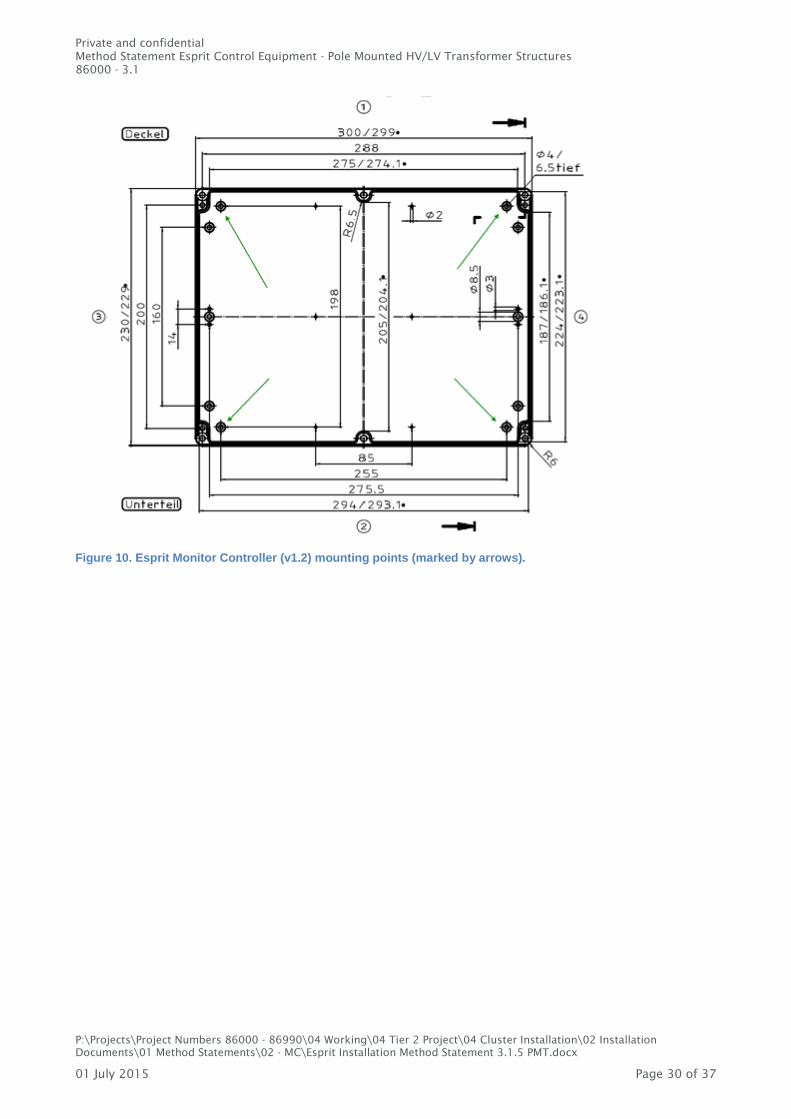
Figure 10. Esprit Monitor Controller (v1.2) mounting points (marked by arrows).
Private and confidential
Method Statement Esprit Control Equipment - Pole Mounted HV/LV Transformer Structures
86000 - 3.1
P:\Projects\Project Numbers 86000 - 86990\04 Working\04 Tier 2 Project\04 Cluster Installation\02 Installation
Documents\01 Method Statements\02 - MC\Esprit Installation Method Statement 3.1.5 PMT.docx
01 July 2015 Page 31 of 37
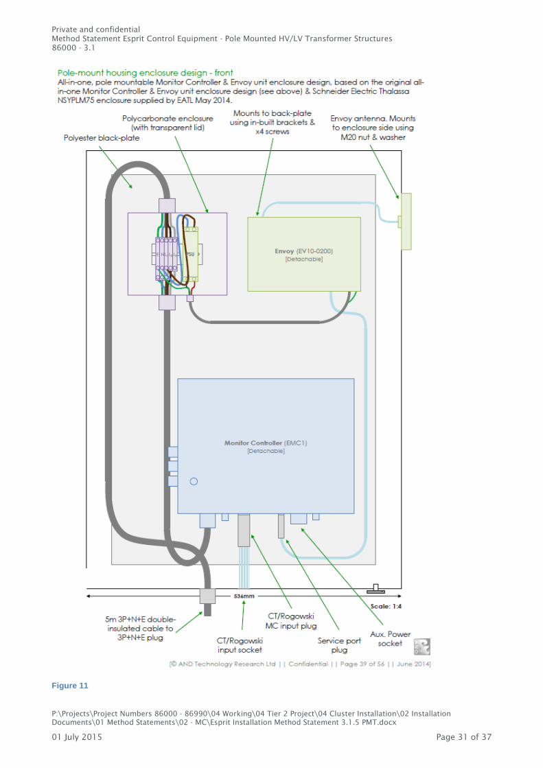
Figure 11
Private and confidential
Method Statement Esprit Control Equipment - Pole Mounted HV/LV Transformer Structures
86000 - 3.1
P:\Projects\Project Numbers 86000 - 86990\04 Working\04 Tier 2 Project\04 Cluster Installation\02 Installation
Documents\01 Method Statements\02 - MC\Esprit Installation Method Statement 3.1.5 PMT.docx
01 July 2015 Page 32 of 37
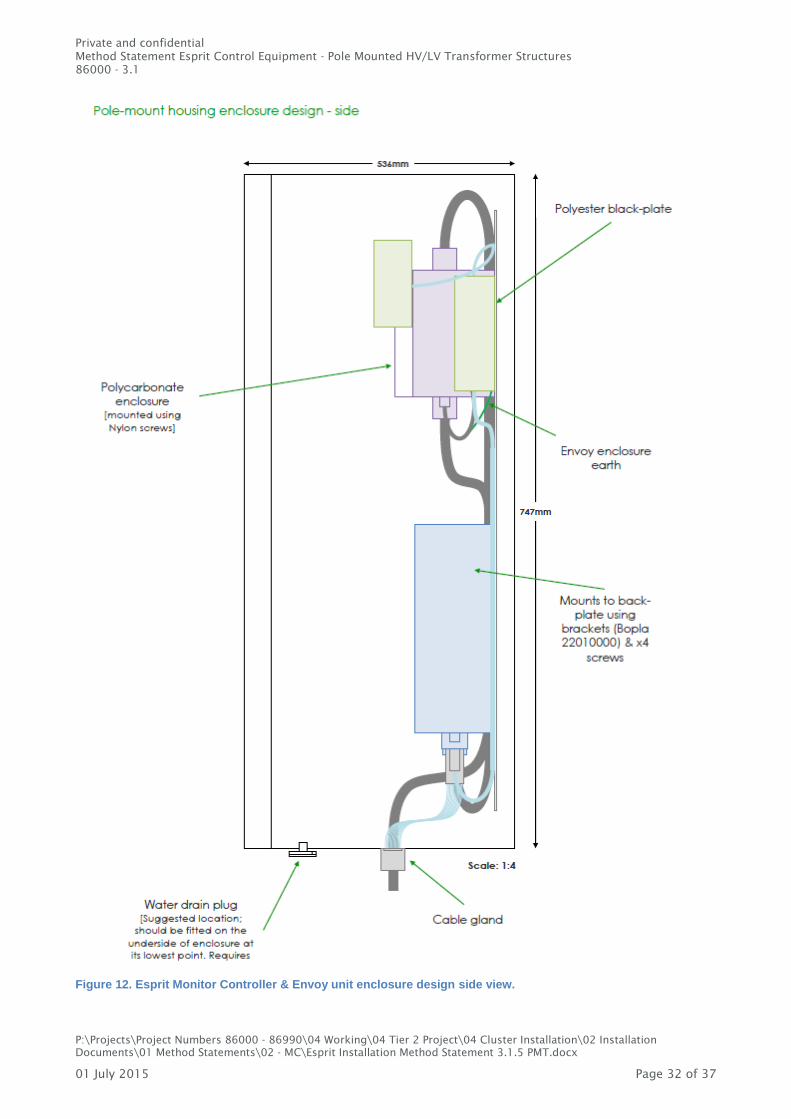
Figure 12. Esprit Monitor Controller & Envoy unit enclosure design side view.
Private and confidential
Method Statement Esprit Control Equipment - Pole Mounted HV/LV Transformer Structures
86000 - 3.1
P:\Projects\Project Numbers 86000 - 86990\04 Working\04 Tier 2 Project\04 Cluster Installation\02 Installation
Documents\01 Method Statements\02 - MC\Esprit Installation Method Statement 3.1.5 PMT.docx
01 July 2015 Page 33 of 37
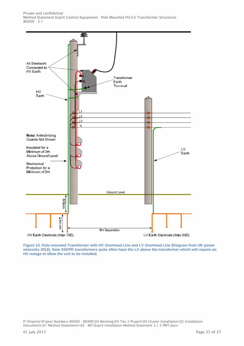
Figure 13. Pole-mounted Transformer with HV Overhead Line and LV Overhead Line (Diagram from UK power networks 2012). Note SSEPD transformers quite often have the LV above the transformer which will require an HV outage to allow the unit to be installed.

Private and confidential
Method Statement Esprit Control Equipment - Pole Mounted HV/LV Transformer Structures
86000 - 3.1
P:\Projects\Project Numbers 86000 - 86990\04 Working\04 Tier 2 Project\04 Cluster Installation\02 Installation
Documents\01 Method Statements\02 - MC\Esprit Installation Method Statement 3.1.5 PMT.docx
01 July 2015 Page 34 of 37
Figure 14. Service Insulation Piercing Connector specification sheet.

www.eatechnology.com
Australia | China | Singapore | UAE | Europe | USA
Main reception: +44(0) 151 339 4181
EA Technology, Capenhurst Technology Park,
Capenhurst, Chester, CH1 6ES, United Kingdom

www.eatechnology.com
Australia | China | Singapore | UAE | Europe | USA
Main reception: +44(0) 151 339 4181
EA Technology, Capenhurst Technology Park,
Capenhurst, Chester, CH1 6ES, United Kingdom
Global Footprint
We provide products, services and support for customers in 90 countries, through our offices in
Australia, China, Europe, Singapore, UAE and USA, together with more than 40 distribution partners.
Our Expertise
We provide world-leading asset management solutions for power plant and networks.
Our customers include electricity generation, transmission and distribution companies, together
with major power plant operators in the private and public sectors.
Our products, services, management systems and knowledge enable customers to:
Prevent outages
Assess the condition of assets
Understand why assets fail
Optimise network operations
Make smarter investment decisions
Build smarter grids
Achieve the latest standards
Develop their power skills