Method of Finite Elements I · 2018-02-18 · Institute of Structural Engineering Page 11 Method of...
43
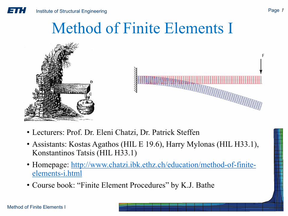
Institute of Structural Engineering Page 1 Method of Finite Elements I • Lecturers: Prof. Dr. Eleni Chatzi, Dr. Patrick Steffen • Assistants: Kostas Agathos (HIL E 19.6), Harry Mylonas (HIL H33.1), Konstantinos Tatsis (HIL H33.1) • Homepage: http:// www.chatzi.ibk.ethz.ch/education/method-of-finite- elements-i.html • Course book: “Finite Element Procedures” by K.J. Bathe Method of Finite Elements I
Transcript of Method of Finite Elements I · 2018-02-18 · Institute of Structural Engineering Page 11 Method of...
Institute of Structural Engineering Page 1
Method of Finite Elements I
• Lecturers: Prof. Dr. Eleni Chatzi, Dr. Patrick Steffen• Assistants: Kostas Agathos (HIL E 19.6), Harry Mylonas (HIL H33.1),
Konstantinos Tatsis (HIL H33.1)• Homepage: http://www.chatzi.ibk.ethz.ch/education/method-of-finite-
elements-i.html• Course book: “Finite Element Procedures” by K.J. Bathe
Method of Finite Elements I

Institute of Structural Engineering Page 2
Method of Finite Elements I
Course Organization
• Lectures posted weekly on the class webpage (last year’s lecture slides also made available)
• Demos posted on the Piazza platform (all class members will receive an email to sign up to Piazza)
• Visiting hours: Prof. Dr. E. Chatzi (by email: [email protected])
• TAs: every Thursday 13:00-15:00 in HIL E10.9. Preregistration at least 24 hours in advance required per Doodle. Posted on Piazza weekly.
• Further questions, will have to be submitted via the Piazza platform. You can also place anonymous Q&As if preferred.
• Please ask questions! They help us better structure the class
Method of Finite Elements I

Institute of Structural Engineering Page 3
Method of Finite Elements I
Course Evaluation
• Performance Assessment via submission of a Project.
• The Project will be divided into 3 parts.
• The full project will be posted on Piazza by 03 March 2018.
• Each part will be described according to the published schedule available on the webpage.
• The project will use part of own code in MATLAB (supported by the material offered in the demos), as well as comparison to a program of your choice (e.g: CUBUS, ABAQUS)
• Groups of 3 members are suggested. Contact us if you are having trouble finding a group.
Method of Finite Elements I

Institute of Structural Engineering Page 4
Method of Finite Elements I
Project Submission
• 19.04.2018: Midterm Project Update
• 24-25.05.2018 & 04-05.06.2018: Final Project Submission -15 min oral submission (printed slides & discussion)
• A Doodle will be distributed for signing up.
• 15.06.2018: Deadline for Final report.
Method of Finite Elements I
Institute of Structural Engineering Page 5
Method of Finite Elements I
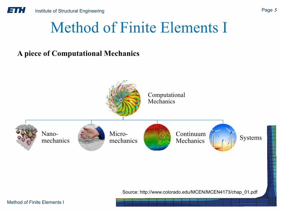
A piece of Computational Mechanics
Method of Finite Elements I
Computational Mechanics
Nano-mechanics
Micro-mechanics
Continuum Mechanics Systems
Source: http://www.colorado.edu/MCEN/MCEN4173/chap_01.pdf

Institute of Structural Engineering Page 6
Method of Finite Elements I
A piece of Computational Mechanics
Method of Finite Elements I©
sd.ru
b.de

Institute of Structural Engineering Page 7
Method of Finite Elements I
A piece of Computational Mechanics
Method of Finite Elements I
Computational Mechanics
Nano-mechanics
Micro-mechanics
Continuum Mechanics
Solids & Structures Fluids Multiphysics
Systems

Institute of Structural Engineering Page 8
Method of Finite Elements I
A piece of Computational Mechanics
Method of Finite Elements I
StructuralMechanics
Statics
Time Invariant
Quasi-static
Dynamics

Institute of Structural Engineering Page 9
Method of Finite Elements I
A piece of Computational Mechanics
Method of Finite Elements I
StructuralMechanics
Statics
Linear Nonlinear
Dynamics
Linear Nonlinear

Institute of Structural Engineering Page 10
Method of Finite Elements I
To present the linear FEM from a structural engineering perspective
To introduce the concept of computation and link this to the analytical approach taught so far.
To help you grasp the fundamental theory, and recognize how it is put in practice
To learn how to put together simple analysis modules from scratch - then recognise this in the software you use.
To understand how the software used in CE offices operate, and understand how to interpret results.
To understand the associated challenges & limitations
Goals of the Class

Institute of Structural Engineering Page 11
Method of Finite Elements I
Remember! Software is continually changing but the core of the methods remains unchanged.
It is the fundamental core that you need to master!
MATLAB will be used as a tool in this path to learning.
It is however nothing but a tool, so feel free shift to any language you feel more comfortable with (if preferred).
Goals of the Class
Institute of Structural Engineering Page 12
Method of Finite Elements I
An overview of the MFE I course MFE: A historical overview Introduction to the use of Finite Elements Why and when to use FEM?
Challenges for a correct use/design
FEM into Practice
Today’s lecture

Institute of Structural Engineering Page 13
Method of Finite Elements I
*lecture sessions come with a Demo in the last part of the session
Course Overview
Date Lecture Project
19.02 Lecture 1: Introduction
26.02 Lecture 2: The Direct Stiffness Method
02.03 Project posted on Piazza
05.03 Lecture 3: Stability & Modal Analysis Project Part I description
12.03 Computer Lab I
19.03 Lecture 4: The Variational Formulation
26.03 Lecture 5: The Isoparametric formulation Project Part II description
09.04 Lecture 6: Prismatic elements

Institute of Structural Engineering Page 14
Method of Finite Elements I
*lecture sessions come with a Demo in the last part of the session
Course OverviewDate Lecture Project
19.04 Midterm Project Update (during TA weekly hours)
23.04 Lecture 7: 2D Elements/The Plate Element Project Part III description
30.04 Lecture 8: Practical application of the MFE - Practical Considerations
07.05 Lecture 9: Practical application of the MFE- Results Interpretation
14.05 Computer Lab II
24-25.05 & 04-05.06 Project Submission (15 min sessions)
28.05 no class

Institute of Structural Engineering Page 15
Method of Finite Elements I
Chapter 1: FE Analysis in brief…The goal of Structural Analysis: Modeling a system by means of approximation.How to do this?Come up with a simplified idealization. This may oftentimes be achieved conceptually.
Example
©M
artin
St-A
man
t
Institute of Structural Engineering Page 16
Method of Finite Elements I
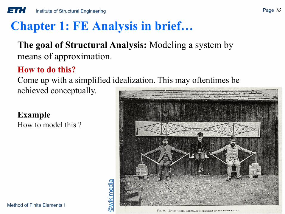
Chapter 1: FE Analysis in brief…The goal of Structural Analysis: Modeling a system by means of approximation.How to do this?Come up with a simplified idealization. This may oftentimes be achieved conceptually.
ExampleHow to model this ?
©w
ikim
edia

Institute of Structural Engineering Page 17
Method of Finite Elements I
The goal of Structural Analysis: Modeling a system by means of approximation.How to do this?Come up with a simplified idealization. This may oftentimes be achieved conceptually.
ExampleHow to model this ?
Break the system down to components.Can we still model this by hand? Perhaps...
©A.D. Magee: A CRITICAL ANAYLSIS OF THE FORTH BRIDGE
Chapter 1: FE Analysis in brief…

Institute of Structural Engineering Page 18
Method of Finite Elements I
The goal of Structural Analysis: Modeling a system by means of approximation.How to do this?Come up with a simplified idealization. This may oftentimes be achieved conceptually.
ExampleWhat if we want to model a critical componentof this system?
Can we still model this by hand? The task is now harder..
©A.D. Magee: A CRITICAL ANAYLSIS OF THE FORTH BRIDGE
Chapter 1: FE Analysis in brief…

Institute of Structural Engineering Page 19
Method of Finite Elements I
Chapter 1: FE Analysis in brief…
Numerical Methods
How to approximate complex structures/domains?
Finite DifferenceMethod
Finite ElementMethod
Boundary ElementMethod
discretization error

Institute of Structural Engineering Page 20
Method of Finite Elements I
Chapter 1: FE Analysis in brief…
Object: A Solid with known mechanical properties. (a skyscraper; a shaft; bio tissue …)
Main Features
• Acting Loads• Boundary: The surface enclosing the geometry • Solid: Interior + Boundary • Boundary conditions: prescribed displacements/tractions on the boundary
FEA was originally developed for solid mechanics applications.

Institute of Structural Engineering Page 21
Method of Finite Elements I
FE Analysis in brief…Problem Statement
undeformed deformed?

Institute of Structural Engineering Page 22
Method of Finite Elements I
How can we use FEM to solve this problem?
The Finite Element Method (FEM) is a numerical method for solution of systems where the governing equations are expressed in the form of partial differential equations (PDEs).
It essentially degenerated the original PDE problem to a system of algebraic equations which are solvable via traditional linear algebra techniques.
Simply put, FEM is a method for breaking down a complex problem/domain into smaller elements that are interconnected and assembled to form an approximation to the original structure.
FE Analysis in brief…

Institute of Structural Engineering Page 23
Method of Finite Elements I
Simply put, FEM is a method for breaking down a complex problem/domain into smaller elements that are interconnected and assembled to form an approximation to the original structure.
Does this ring a bell?
Baustatik II – The Direct Stiffness Method
FE Analysis in brief…
X
1 2
5
1 2
3
4
5 6
3 4
Institute of Structural Engineering Page 24
Method of Finite Elements I
How was FEM historically formed? (source: Carlos A. Felippa)
The MFE is the confluence of three ingredients: matrix structural analysis, variational approach and a computer.
Theoretical Formulation1. “Lösung von Variationsproblemen” by W. Ritz in 19082.“Weak formulation” by B. Galerkin in 19153.“Mathematical foundation” by R. Courant ca. 1943
MFE Historical Evolution

Institute of Structural Engineering Page 25
Method of Finite Elements I
How was FEM historically formed? Who can be mostly blamed for the reign of FEM?1950s, M.J. Turner at Boeing (aerospace industry in general): Direct Stiffness Method
“Turner got Boeing to commit resources to it while other aerospace companies(Douglas, Lockheed, Rockwell, ...) were mired in the Force Method swamp. Heoversaw the development of the first continuum based finite elements, theconsequent creation and expansion of the DSM, and its first application tononlinear problems.In addition to Turner, major contributors to current practice include: B. M. Irons,inventor of isoparametric models, shape functions, the patch test and frontalsolvers; R. J. Melosh, who recognized the Rayleigh-Ritz link and systematizedthe variational derivation of stiffness elements; and E. L. Wilson, who developedthe first open source (and widely imitated and distributed) FEM and matrixsoftware”
(source: Carlos A. Felippa)
MFE Historical Evolution
Institute of Structural Engineering Page 26
Method of Finite Elements I
How was FEM historically formed? (source: Carlos A. Felippa)
Who were the “populizers”?1. Matrix formulation of structural analysis by Agyris in 1954“As a consultant to Boeing in the early 1950s, Argyris, a Force Method expert then at Imperial College, received reports from Turner’s group, and weaved the material into the above influential publication. He was the first to construct a displacement-assumed continuum element.”2. The term ‚Finite Element‘ was coined by Clough in 1960“R.W. Clough and H.C. Martin, then junior professors at U.C. Berkeley and U. Washington, respectively, spent “faculty internship” summers at Turner’s group during 1952–53. The result of this seminal collaboration was a celebrated paper, widely considered the start of the present FEM.”3. First book on FEM by Zienkiewicz and Cheung in 1967“Olek Zienkiewicz, originally an expert in finite difference methods was convinced in 1958 by Clough to try FEM. He went on to write the first textbook on the subject”
MFE Historical Evolution
Institute of Structural Engineering Page 27
Method of Finite Elements I
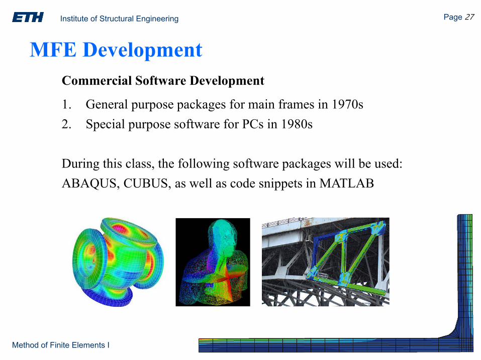
Commercial Software Development
1. General purpose packages for main frames in 1970s2. Special purpose software for PCs in 1980s
During this class, the following software packages will be used:ABAQUS, CUBUS, as well as code snippets in MATLAB
MFE Development

Institute of Structural Engineering Page 28
Method of Finite Elements I
FEM is a big success story, because it…
1. can handle complex geometries
2. can handle a wide variety of engineering problems
- mechanics of solids & fluids
- dynamics/heat/electrostatic problems…
3. can handle complex restraints & loading
4. is very well suited for computation

Institute of Structural Engineering Page 29
Method of Finite Elements I
What is a Finite Element?
Source: http://www.colorado.edu/MCEN/MCEN4173/chap_01.pdf
Find the perimeter L of a circle of diameter dWe know that L = πd.
elements
nodes
Lij
Approximation via Inscribed PolygonThe element length is Lij = 2r sin(π/n). Since all elements have the same length, the polygon perimeter is Ln = n LijHence the approximation to π is πn = Ln/d = n sin(π/n).

Institute of Structural Engineering Page 30
Method of Finite Elements I
What is a Finite Element?
Source: http://www.colorado.edu/MCEN/MCEN4173/chap_01.pdf
elements
nodes
Lij
n πn = n sin(π/n)1 0.0000000000000002 2.0000000000000004 2.8284271247461908 3.06146745892071816 3.12144515225805232 3.13654849054593964 3.140331156954753128 3.141277250932773256 3.141513801144301
Rectification of Circle by Inscribed Polygons (“Archimedes FEM”)
Institute of Structural Engineering Page 31
Method of Finite Elements I
Institute of Structural Engineering Page 32
Method of Finite Elements I
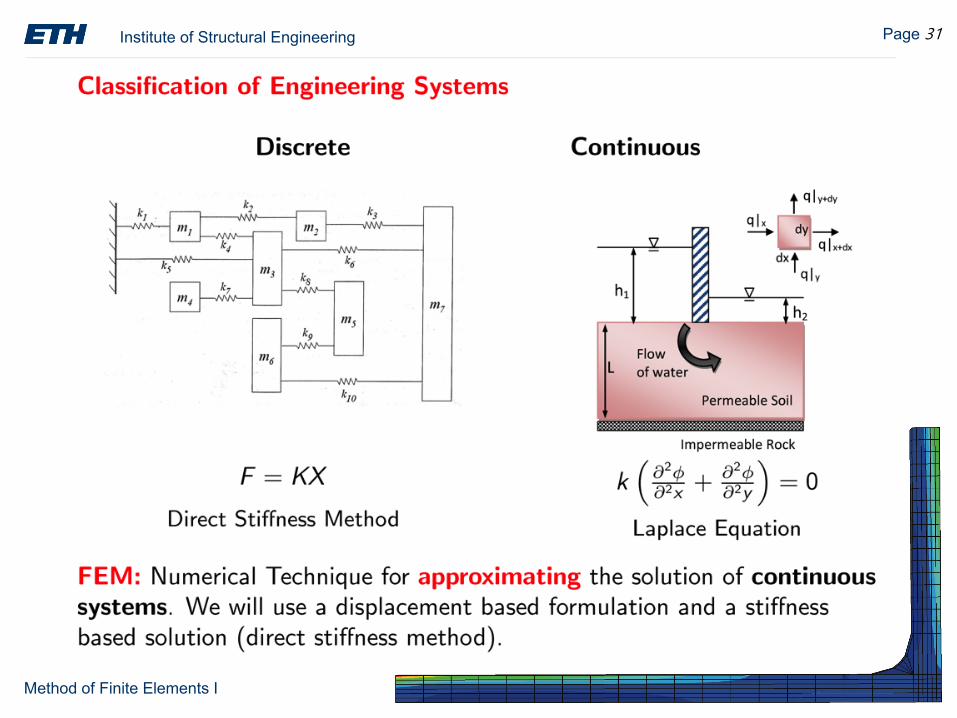
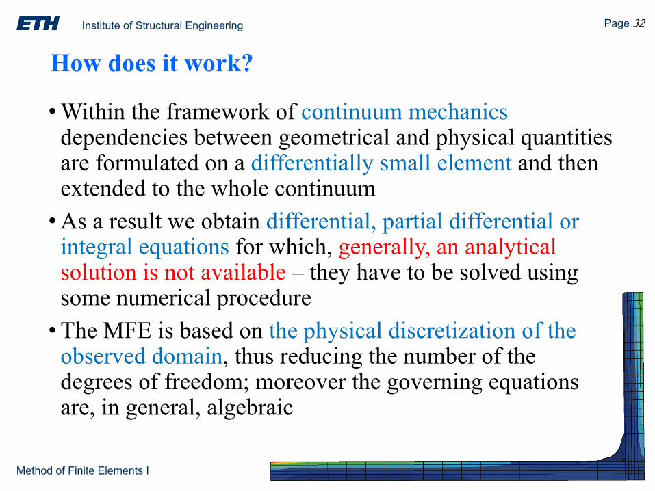
•Within the framework of continuum mechanics dependencies between geometrical and physical quantities are formulated on a differentially small element and then extended to the whole continuum•As a result we obtain differential, partial differential or
integral equations for which, generally, an analytical solution is not available – they have to be solved using some numerical procedure•The MFE is based on the physical discretization of the
observed domain, thus reducing the number of the degrees of freedom; moreover the governing equations are, in general, algebraic
How does it work?

Institute of Structural Engineering Page 33
Method of Finite Elements I
Let’s follow Clough’s trip:
“When I arrived in the summer of 1952, Jon Turner asked me to work on thevibration analysis of a delta wing structure. Because of its triangular plane form, thisproblem could not be solved by procedures based on standard beam theory; so I spentthe summer of 1952 trying to formulate a delta wing model built up of an assembly ofone-dimensional beams and struts. However, the results of deflection analysis basedon this type of mathematical model were in very poor agreement with data obtainedfrom laboratory tests of a scale model of a delta wing. My final conclusion was thatmy summer’s work was a total failure — however, at least I learned what did notwork.Spurred by this disappointment, I decided to return to Boeing for the summer facultyprogram of 1953. During the winter, I stayed in touch with Jon Turner so I was ableto rejoin the structural dynamics unit in June.”
(source: Carlos A. Felippa)
Why & When to use FEM?

Institute of Structural Engineering Page 34
Method of Finite Elements I
Let’s follow Clough’s trip:
“The most important development during the winter was that Jon suggested we try toformulate the stiffness properties of the wing by assembling plane stress plates ofeither triangular or rectangular shapes. So I developed stiffness matrices for plates ofboth shapes, but I decided the triangular form was much more useful because suchplates could be assembled to approximate structures of any configuration. Moreover,the stiffness properties of the individual triangular shapes could be calculated easilybased on assumptions of uniform states of normal stress in the X and Y directionscombined with a uniform state of shear stress. Then the stiffness of the completestructure was obtained by appropriate addition from the contributions of theindividual pieces.
The remainder of the summer of 1953 was spent in demonstrating that deflectionscalculated for structures formed of assemblies of triangular elements agreed well withlaboratory measurements on the actual physical models.”
Why & When to use FEM?(source: Carlos A. Felippa)

Institute of Structural Engineering Page 35
Method of Finite Elements I
How does it work?
Physical ModelDescribe the problem: Simplify a real engineering problem into a
problem that can be solved by FEA
FE modelDiscretize/mesh the solid, define material properties, apply boundary conditions
TheoryChoose approximate functions, formulate linear equations, and
solve equations
ResultsObtain, visualize and explain
the results
Pre-processor
Post-processor Solver
Source: http://www.colorado.edu/MCEN/MCEN4173/chap_01.pdf

Institute of Structural Engineering Page 36
Method of Finite Elements I
Steps in the MFEStep 1: Problem Formulation

Institute of Structural Engineering Page 37
Method of Finite Elements I
Steps in the MFEStep 2: Discretization/MeshingThe continuum is discretized using a mesh of finite elements.

Institute of Structural Engineering Page 38
Method of Finite Elements I
Steps in the MFEDiscretization: The continuum is discretized using a mesh of finite elements.
These elements are connected at nodes located on the element boundaries.
e
Institute of Structural Engineering Page 39
Method of Finite Elements I
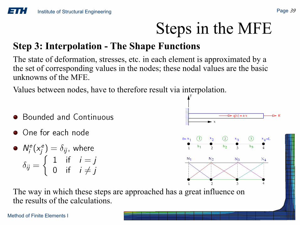
Steps in the MFEStep 3: Interpolation - The Shape FunctionsThe state of deformation, stresses, etc. in each element is approximated by a the set of corresponding values in the nodes; these nodal values are the basic unknowns of the MFE.Values between nodes, have to therefore result via interpolation.
The way in which these steps are approached has a great influence on the results of the calculations.

Institute of Structural Engineering Page 40
Method of Finite Elements I
•The MFE is only a way of solving the mathematical model •The solution of the physical problem depends on the
quality of the mathematical model – the choice of the mathematical model is crucial•The chosen mathematical model is reliable if the required
response can be predicted within a given level of accuracy compared to the response of a very comprehensive (highly refined) mathematical model•The most effective mathematical model for the analysis is
the one that gives the required response with sufficient accuracy and at the lowest computational toll
Challenges
Institute of Structural Engineering Page 41
Method of Finite Elements I
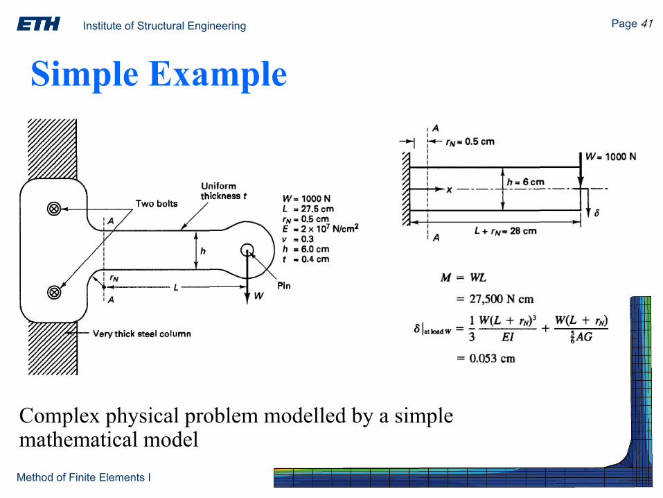
Complex physical problem modelled by a simple mathematical model
Simple Example

Institute of Structural Engineering Page 42
Method of Finite Elements I
Detailed reference model – 2D plane stress model
Simple Example

Institute of Structural Engineering Page 43
Method of Finite Elements I
• Choice of mathematical model must correspond to desired response• The most effective mathematical model delivers reliable
answers with the least amount of effort• Any solution (including MFE) of a mathematical model is
limited to information contained in or fed into the model: bad input – bad output (garbage in – garbage out)• Assessment of accuracy is based on comparisons with the
results from very comprehensive models – but in practice it has to be based on experience (experiments…)• The engineer (user) should be able to judge the quality of the
obtained results (i.e. for plausibility)
Considerations