Method of Developing and Equipping a 21st Centaury Haulage ...
23
1/23 Method of Developing and Equipping a 21 st Centaury Haulage at Depth JD SPIES General Manager, (Moab Khotsong Mine) A BLOM Section Manager, (Moab Khotsong Mine) SYNOPSIS This paper describes the methodology and design of tunneling at depth of the Moab Khotsong project. It deals more in depth with the innovative excavation techniques and tunneling standards employed whilst developing through weak MB 10 guartzites in order to access the orebody safely. INTRODUCTION The Moab Khotsong project forms part of Anglogold Vaal River Operations. The operation in addition to the project consists of three other production mines situated near Klerksdorp in the North West Province (see Locality Plan – Figure 1). Following the successful exploration of the down dip extension of the Vaal Reef, situated to the south of the Great Noligwa Mine, it was decided to exploit the orebody. The orebody lies at depths between 2 000m and 3 800m below surface with only limited quantities of ore lying above 2 300m. The geological structure is complex and highly faulted with large fault loss areas. Due to the size of shaft pillars, as well as the fact that they cannot provide the necessary protection against rock pressures at depth, it was decided to site the new shaft in Great Noligwa’s lease area. This provided the opportunity of extracting the shaft pillar before the shaft was excavated and equipped but required the development of long access tunnels to reef. The main surface shaft and sub – vertical has been sunk and equipped down to a depth of 2 300m and 3 164m respectively (see Shaft Layout – Figure 2 & 3). The infrastructure and the access development on the first two levels will be excavated by means of a mid shaft loading system. Inter level spacing on these levels are 300m apart, and this decision was taken in order to reduce access development meters to the reef blocks which are 2 500m away. A mid shaft loading system which consists of a single skip / cage combination with a 1 000 ton/day hoisting capacity, limits the volume of development that can be excavated and serviced. GEOLOGICAL INFORMATION The upper levels are situated in the Commonage Formation, which is a fairly monotonous quartzite with scattered white grains. The bedding thickness can vary up to 135 cm with intermittent thin shale bands that could cause stability problems (avg. U.C.S.: 121 – 235 MPa). Abundant small scale faulting is present as well as associated joints giving the rock formation a fractured appearance. Major faults are also present with numerous sill and dyke intersections.
Transcript of Method of Developing and Equipping a 21st Centaury Haulage ...

1/23
MMeetthhoodd ooff DDeevveellooppiinngg aanndd EEqquuiippppiinngg aa 2211sstt CCeennttaauurryy
HHaauullaaggee aatt DDeepptthh
JD SPIES
General Manager, (Moab Khotsong Mine)
A BLOM
Section Manager, (Moab Khotsong Mine)
SYNOPSIS
This paper describes the methodology and design of tunneling at depth of the Moab Khotsong
project. It deals more in depth with the innovative excavation techniques and tunneling standards
employed whilst developing through weak MB 10 guartzites in order to access the orebody safely.
INTRODUCTION
The Moab Khotsong project forms part of Anglogold Vaal River Operations. The operation in
addition to the project consists of three other production mines situated near Klerksdorp in the
North West Province (see Locality Plan – Figure 1). Following the successful exploration of the
down dip extension of the Vaal Reef, situated to the south of the Great Noligwa Mine, it was
decided to exploit the orebody.
The orebody lies at depths between 2 000m and 3 800m below surface with only limited quantities
of ore lying above 2 300m. The geological structure is complex and highly faulted with large fault
loss areas. Due to the size of shaft pillars, as well as the fact that they cannot provide the necessary
protection against rock pressures at depth, it was decided to site the new shaft in Great Noligwa’s
lease area. This provided the opportunity of extracting the shaft pillar before the shaft was
excavated and equipped but required the development of long access tunnels to reef. The main
surface shaft and sub – vertical has been sunk and equipped down to a depth of 2 300m and 3 164m
respectively (see Shaft Layout – Figure 2 & 3).
The infrastructure and the access development on the first two levels will be excavated by means of
a mid shaft loading system. Inter level spacing on these levels are 300m apart, and this decision
was taken in order to reduce access development meters to the reef blocks which are 2 500m away.
A mid shaft loading system which consists of a single skip / cage combination with a 1 000 ton/day
hoisting capacity, limits the volume of development that can be excavated and serviced.
GEOLOGICAL INFORMATION
The upper levels are situated in the Commonage Formation, which is a fairly monotonous quartzite
with scattered white grains. The bedding thickness can vary up to 135 cm with intermittent thin
shale bands that could cause stability problems (avg. U.C.S.: 121 – 235 MPa). Abundant small
scale faulting is present as well as associated joints giving the rock formation a fractured
appearance. Major faults are also present with numerous sill and dyke intersections.

2/23
LOCALITY PLAN
TAU LEKOA
MINE
KOPANANG MINE
GREAT NOLIGWA
MINE
MOAB KHOTSONG
MINE
N
ORKNEY
KLERKSDORP
PROPOSED DECLINES FOR LOWER
REEF BLOCKS
101 LEV
95 LEV
85 LEV
SOUTH
VAAL
LEASE
EAST VAAL
LEASE
SUB RV
SHAFT
MAIN SHAFT
REEF
FAULT
FUTURE MAIN SHAFT EXTENSION
102 LEV
Figure 1
Figure 2

3/23
Figure 3
TUNNELING
Strategy
Definite tunneling strategies had to be formulated for Moab Khotsong as current mining methods
cannot simply be extended to deep level mines without compromising safety and would require
significant modifications to standards, work practices and mine design. During station development
on the main shaft it became apparent that because of poor ground conditions, conventional methods
of tunneling would not suffice on Moab Khotsong Mine where greater depths are anticipated. This
therefore necessitated that certain principal decisions be made that will ensure safety, be practical
and cost effective. In addition these decisions should be aligned with the horizontal transport vision
of a 21st century mine. The principal decisions and any subsequent decisions taken will be
discussed in detail under each aspect of tunneling.
Mine Design
The decision was taken to develop a main haulage and return airway with connecting crosscuts
100m apart on the two levels serviced by the mid shaft loading system because of the hoisting
constraint (see Figure 4). This limited the planned rate of advance to 180m per level per month (see
Production Profile).
> >
11F & G
11C
11B
11H
11E 11D
11A
Sub Main Shaft
RV Shaft Main Shaft
Lease Boundary
MOAB KHOTSONG PLAN
Great Noligwa
N
MINED ABOVE 101 LEV.
MINED BELOW 101 LEV

4/23
85 LEVE
L
MB 10 Quartz
ite
85 LEVEL85 LEVEL
Figure 4
Equipment Selection
From a workshop involving Technical Development Services it was decided to use handheld
jackhammers due to the length of round and support requirements in conjunction with LHD’s.
Tunneling commenced in August 1998 with jackhammers and diesel driven LHD’s in order to
complete all the infrastructure development around the shaft barrel. Subsequently the necessary
infrastructure was installed to accommodate track – bound equipment to follow 100m behind the
access development with electro – hydraulic LHD’s tipping directly into hoppers at established
tipping points.
MM..SS..DD.. PPRROODDUUCCTTIIOONN PPRROOFFIILLEE
0
50
100
150
200
250
300
350
400
450
Dev Act 106 274 317 348 366 365
Dev Plan 80 120 260 300 340 360 360 360 180 260 300 340 360 360 360 360 380 400
Jul-99 Aug-99 Sep-99 Oct-99 Nov-99 Dec-99 Jan-00 Feb-00 Mar-00 Apr-00 May-00 Jun-00 Jul-00 Aug-00 Sep-00 Oct-00 Nov-00 Dec-00

5/23
Mining Cycle
From the outset it was envisaged that 3 crews would be required to work 12 hour shifts. The main
reason behind this decision was to balance the mining cycle and to ensure that each crew could be
held accountable for the work required per shift. This required each crew to blast, clean and fully
support 2 ends per shift including the wetcreting of these ends (see Figure 5). Working 12 hour
shifts also reduced man traveling time in the shaft, thereby increasing rock and material hoisting
available time.
Figure 5
Tunnel Dimensions
The size and number of access tunnels in all future deep level mines will mainly depend on
ventilation requirements, such as system pressure losses and acceptable air velocities. This was also
relevant for the Moab project with an area requirement of 16m² per tunnel, which equates to an end
4.4m high x 4.5m wide (see Figure 6).
Tunnel Profiles
FLAC 3D computer modeling done by ITASCA was used to obtain the optimum tunnel profile.
Aspects considered for the various layouts were:
• The optimum shape of the tunnel in quartzite and shales;
• Support requirements for the optimum shape under virgin stress;
• The peak loading sustainable by each support system.
BAR FACE
SHOTCRETE
CLEAN
20 min
90 min
210 min
MARK OFF
END 1
END 2
20 min
50 min
0.5
hr5hr 30 min 5 hr 30 min
0.5
hr
12hr
EXTEND SERVICES
40 minL.H.D. MAINTENANCE
INSTALL PLATFORM
DRILL & INSTALL SUPPORT 90 min
DRILL FACE
CHARGE UP
RE ENTRY
BLAST
45 min
45 min
5 min
30 min
130 min
BAR FACE
SHOTCRETE
CLEAN
20 min
90 min
180 min
MARK OFF 20 min
50 min
EXTEND SERVICES
40 minL.H.D. MAINTENANCE
INSTALL PLATFORM
DRILL & INSTALL SUPPORT 90 min
DRILL FACE
CHARGE UP
RE ENTRY
BLAST
45 min
45 min
5 min
30 min
130 min

6/23
100100
937
1125
210
0
160
0
500 1750 188
762 1300
4500
400
160
02
40
0
440
0
A stress value corresponding to a virgin stress value for a depth of 2 850 m below surface
(93 Level) was used in the modeling. For the five different profiles modeled, rectangular, circular,
elliptical, elliptically arched and circular arched, the ellipse with a width to height ratio of 1.3 was
found to be most favorable profile. For practical reasons the elliptically arched profile was
therefore adopted (see Figure 6).
Figure 6
4.4 x 4.5 Tunnel

7/23
Breaking
Due to the fractured nature of the ground, the decision was made to limit the length of the blast
holes to 2.5m maximum. This eliminated the use of drill rigs both for utilization purposes as well
as cost effectiveness. Protecting machine operators from this environment will be discussed under
support. Due to the size of the required ends, breakaways and holing positions were identified as
potential high risk areas and certain well defined action steps have been put into place to counter
this (see the following).
Holings
Whenever two excavations come to within 20m of holing into one another, one of the ends shall be
stopped. This end will then be examined for misfires and shall have the primary support installed to
within 1m from the face position, with wetcrete being applied right up to the face on both side-walls
and hanging-wall (see Sketch 1).
Sketch 1
Breakaways
All breakaways are blasted according to a specific sequence in order to ensure that minimal blasting
fractures are induced at bull-nose positions (see Sketch 2).
ADVANCING FACE
HOLING POINT
4M
3M
SHOTCRETE UP
TO FACE BEFORE
HOLING
AREA IN WHICH THE PRIMARY
SUPPORT MUST BE REDUCED
TO A 1M DIAMOND PATTERN
4,5 M LONG MECHANICAL ANCHORS

8/23
Sketch 2
Underhand Development Faces
Due to frequent strain bursting occurring on the development faces, decisions were taken to carry
all the faces underhand. This would provide some means of protection for the workers in that the
rock if dislodged would slide down the face and not fall over.
Charging Up and Blast Initiation
Smooth-wall blasting is done using conventional cartridge explosives to charge up the perimeter
holes, and ammonium nitrate based explosives are used on the remaining holes. Conventional fuse
and igniter cord is used in conjunction with the above mentioned explosives. The blast is initiated
by means of battery operated shot exploders from a safe designated blasting point.
Trails conducted with shock tubes over the last three months on one particular level, not only
improved the face advance from 1.7m to 2.2m per blast but also reduced the explosive accessories
cost by R67 per meter. It is envisaged that when the trails have been concluded all development
will then utilize shock tubes.
Support
The depth at which tunneling is taking place has a significant effect on the ground conditions.
Strain bursting which is the sudden release of stored strain energy, close to the face, occurs
frequently when bedding planes with a width of > 1,2m are exposed. The mechanism of failure is
the buckling of the thin slabs created when large bedding planes are exposed (see Photo 1). The
high vertical stress which acts on the thin slab cause it to buckle inwards and results in the sudden
release of the strain energy. Counter measures employed, are de-stressing the face and installing
additional support into the > 1,2m bedding planes.
CROSS CUT
BREAK-AWAY
26 m RADIUS
MINIMUM
2.32.3
3,0
3.6
4.4 5.5
6.8
8.5
1
2 3
4 5
6 7
8
4.5m
9
0 2 4 6 8 10 12 14 16 17,5
10.0
10m
KEY NOTES
•All breakaways must be started according to survey notes
• Drill and blast rounds 2, 3 and 4 concurrently with the advancing face
• Advance the end 10m past the bullnose position
• Drill and blast a 4,5 m wide round into the sidewall at position 1 and support to standard
• Advance rounds 5 to 9 until a straight face is established
• When the breakaway has advanced 10 m install a waterblast
• All survey notes must indicate the frog position of the rail turnout

9/23
By adding construction lines the bulging of the upper sidewall becomes more evident.
Mirror zone
Transition zone Hackled
region
On three occasions large rocks (± 2 tons) were ejected into the excavations, and this necessitated
that the principal decision was made to protect the drilling crews by means of installing wire mesh
on the face, unsupported hanging and sidewall areas.
Photo 1
Photo showing strain bursting
10/23
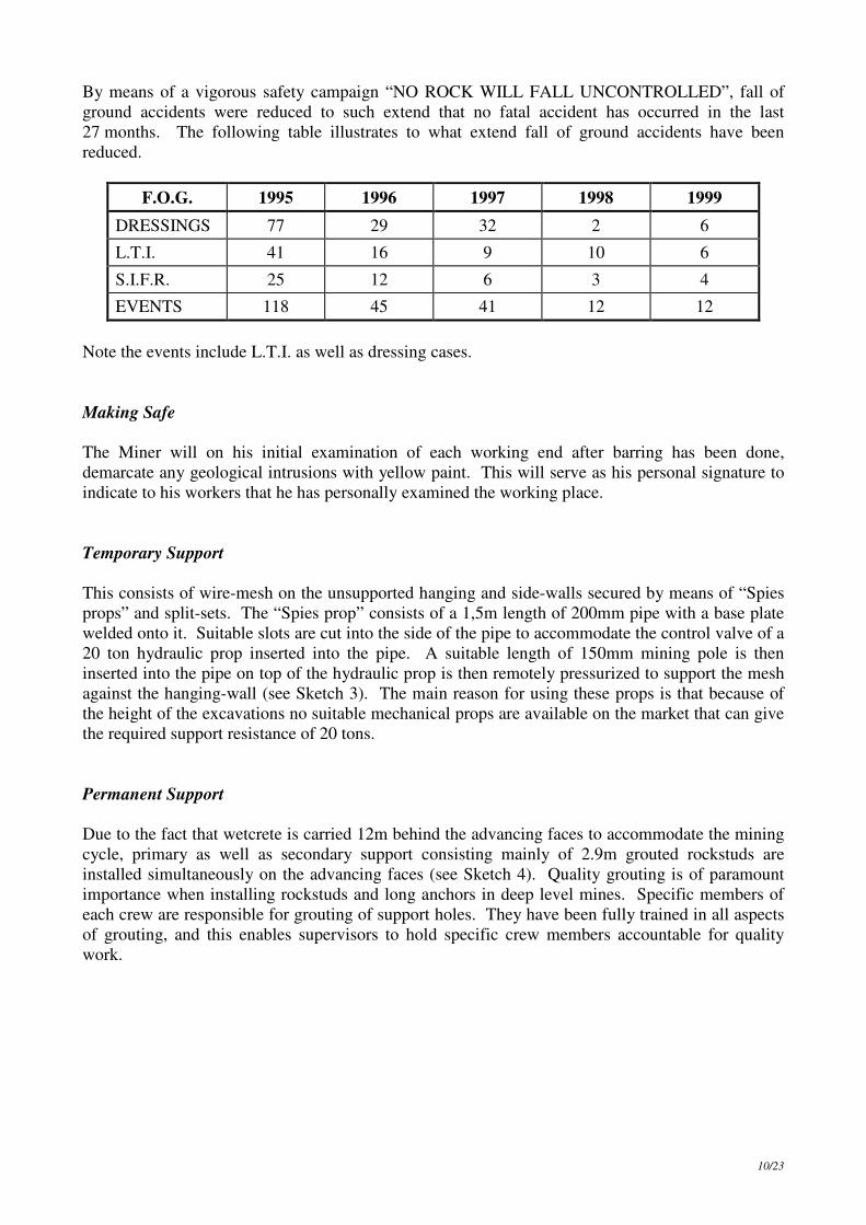
By means of a vigorous safety campaign “NO ROCK WILL FALL UNCONTROLLED”, fall of
ground accidents were reduced to such extend that no fatal accident has occurred in the last
27 months. The following table illustrates to what extend fall of ground accidents have been
reduced.
F.O.G. 1995 1996 1997 1998 1999
DRESSINGS 77 29 32 2 6
L.T.I. 41 16 9 10 6
S.I.F.R. 25 12 6 3 4
EVENTS 118 45 41 12 12
Note the events include L.T.I. as well as dressing cases.
Making Safe
The Miner will on his initial examination of each working end after barring has been done,
demarcate any geological intrusions with yellow paint. This will serve as his personal signature to
indicate to his workers that he has personally examined the working place.
Temporary Support
This consists of wire-mesh on the unsupported hanging and side-walls secured by means of “Spies
props” and split-sets. The “Spies prop” consists of a 1,5m length of 200mm pipe with a base plate
welded onto it. Suitable slots are cut into the side of the pipe to accommodate the control valve of a
20 ton hydraulic prop inserted into the pipe. A suitable length of 150mm mining pole is then
inserted into the pipe on top of the hydraulic prop is then remotely pressurized to support the mesh
against the hanging-wall (see Sketch 3). The main reason for using these props is that because of
the height of the excavations no suitable mechanical props are available on the market that can give
the required support resistance of 20 tons.
Permanent Support
Due to the fact that wetcrete is carried 12m behind the advancing faces to accommodate the mining
cycle, primary as well as secondary support consisting mainly of 2.9m grouted rockstuds are
installed simultaneously on the advancing faces (see Sketch 4). Quality grouting is of paramount
importance when installing rockstuds and long anchors in deep level mines. Specific members of
each crew are responsible for grouting of support holes. They have been fully trained in all aspects
of grouting, and this enables supervisors to hold specific crew members accountable for quality
work.

11/23
2,0
m
0 ,7 5 m 3 ,6 m U n s u p p o rte d A re a
4,4
m
0 ,5 m
2 ,0 m
Spie
s P
rop
Spie
s P
rop
D r il l P la tfo rm m in . 3 ,0 m f ro m fa c e
W ir e m e s h o v e r la p o f 0 ,2 m
h e ld to g e th e r w ith B e llw ire
0 ,5 m m a x
Wir
e m
esh s
ecure
d to 4
,6m
fro
m face
S e c tio n
P e rm a n e n t S u p p o r t
P L A N K D R IL L IN G P L A T F O R M A N D P O S IT IO N IN G O F
S P IE S P R O P S IN A 4 ,4 M X 4 ,5 M E N D
S lin g E y e b o lt
S a fe ty C h a in
L a d d e r
Underhand face
Sketch 3
Sketch 4
Rock Engineering Training
The need for rock engineering training for Moab Khotsong employees was identified some time
back, as most of the employees had no previous deep level mining experience. All supervisors
therefore had to attend a formal accredited training course. In addition to this an informal “in
house” training course was compiled by the Moab Rock Engineering Department, which was based
on actual accident investigations and local modes of rock failure which was presented to all
Primary Support Standard For 4,4m High and 4,5m Wide
Excavations 1,5m Diamond Pattern
Centr
e L
ine
Section View of 4,4m x 4,5m Excavation
2,9m long, 20mm diameter
full column grouted
rockstuds
Grade Line
4,5m
4,4m
0,75m
NB! : - The two rows of support are offset by 0,75m (See Sidewall View)
2,0m
1,5m
1,5m
0,75m
0,75m
Side wall Vie w of 4,4m x 4,5m Excavation
2,9m long, 20mm diameter
full column grouted
rockstuds

12/23
employees (see Examples 1 – 3). The training also included standards and basic strata control
principals. These standards are dynamic and are updated as new experiences are gained, as we are
pioneering development and sinking in the Klerksdorp area at depths beyond 3 km and cannot gain
any experience from any adjacent mine.
In order to emphasize and create understanding a “Rock Engineering Zero Tolerance Board”
incorporating much of the material used in the informal course is displayed at all waiting places
underground. Models of major geological intersections are also made to create understanding and
to plan the sequence of events in order to traverse the intersection safely.
Example 1
Example 2
PREVENTING STRAIN BURSTING OF SIDE WALLS
BUCKLING OF THIN SLABS
IDENTIFY BEDS GREATER THAN 1,2 M THICK
1,2 M
HIGH VERTICAL STRESS
HIGH VERTICAL STRESS
INSTALL ROCKSTUDS IN THESE BEDS PRIOR TO ALL OTHER SUPPORT
STRAIN BURSTING
ALWAYS WORK UNDER MESH CANOPY
1,2 M
LARGE POTENTIAL FOR STRAIN BURSTING
ZONE OF HIGH STRESS ADJACENT TO FACE PRE - CONDITIONING HOLES MOVE ZONE OF HIGH STRESS FURTHER INTO THE SOLID
PRE - CONDITIONING HOLES
PREVENTING STRAIN BURSTING OF FACE
IDENTIFY BEDS GREATER THAN 1,2 M THICK
FRONT VIEW SHOWING POSITION OF PRE - CONDITIONING HOLES ALTERNATE POSITIONS EVERY DAY
BLAST HOLES
13/23
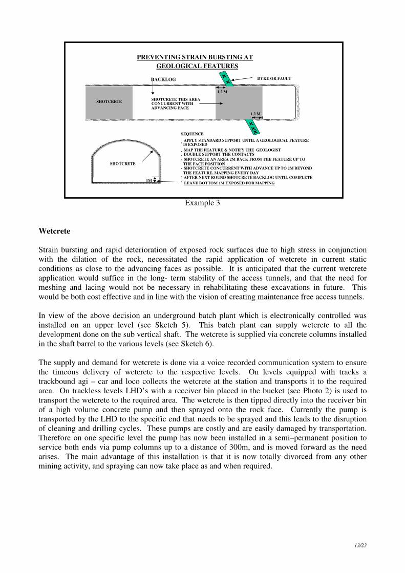
Example 3
Wetcrete
Strain bursting and rapid deterioration of exposed rock surfaces due to high stress in conjunction
with the dilation of the rock, necessitated the rapid application of wetcrete in current static
conditions as close to the advancing faces as possible. It is anticipated that the current wetcrete
application would suffice in the long- term stability of the access tunnels, and that the need for
meshing and lacing would not be necessary in rehabilitating these excavations in future. This
would be both cost effective and in line with the vision of creating maintenance free access tunnels.
In view of the above decision an underground batch plant which is electronically controlled was
installed on an upper level (see Sketch 5). This batch plant can supply wetcrete to all the
development done on the sub vertical shaft. The wetcrete is supplied via concrete columns installed
in the shaft barrel to the various levels (see Sketch 6).
The supply and demand for wetcrete is done via a voice recorded communication system to ensure
the timeous delivery of wetcrete to the respective levels. On levels equipped with tracks a
trackbound agi – car and loco collects the wetcrete at the station and transports it to the required
area. On trackless levels LHD’s with a receiver bin placed in the bucket (see Photo 2) is used to
transport the wetcrete to the required area. The wetcrete is then tipped directly into the receiver bin
of a high volume concrete pump and then sprayed onto the rock face. Currently the pump is
transported by the LHD to the specific end that needs to be sprayed and this leads to the disruption
of cleaning and drilling cycles. These pumps are costly and are easily damaged by transportation.
Therefore on one specific level the pump has now been installed in a semi–permanent position to
service both ends via pump columns up to a distance of 300m, and is moved forward as the need
arises. The main advantage of this installation is that it is now totally divorced from any other
mining activity, and spraying can now take place as and when required.
1,2 M
1,2 M
DYKE OR FAULT
SHOTCRETE THIS AREA CONCURRENT WITH ADVANCING FACE
BACKLOG
SHOTCRETE
SEQUENCE • APPLY STANDARD SUPPORT UNTIL A GEOLOGICAL FEATURE IS EXPOSED • MAP THE FEATURE & NOTIFY THE GEOLOGIST • DOUBLE SUPPORT THE CONTACTS • SHOTCRETE AN AREA 2M BACK FROM THE FEATURE UP TO THE FACE POSITION • SHOTCRETE CONCURRENT WITH ADVANCE UP TO 2M BEYOND THE FEATURE, MAPPING EVERY DAY • AFTER NEXT ROUND SHOTCRETE BACKLOG UNTIL COMPLETE • LEAVE BOTTOM 1M EXPOSED FOR MAPPING
PREVENTING STRAIN BURSTING AT GEOLOGICAL FEATURES
SHOTCRETE
1M

14/23
Sketch 5
Sketch 6
95 L 100 L 101 L 102 L
85 L
SURFACE BATCH PLANT FOR BULK CONCRETE SUPPLY
MAIN SHAFT COLUMN
TRANSFER PUTZMIESTER LAUNDER RV SHAFT CONCRETE COLUMNS
AGGREGATE STORAGE BINS
TRANSFER BELT
MSD CONCRETE COLUMNS
MOVABLE FEED CHUTE
UNDERGROUND BATCH PLANT
BATCH PLANT
102 LEV.
RECEIVER
WETCRETE TRANSPORT SYSTEM
VERTICAL PLANE
76 LEV.
85 LEV.
95 LEV.
100 LEV.
101 LEV.
KETTLE & 300M
108M
294M
42M
48M

15/23
Photo 2
Wetcrete is applied to within 12m meters from the face after the blast to coincide with the
ventilation standard. Dedicated trained crews apply the shotcrete to the rock faces. The rock face is
barred, properly washed down and all rock-studs are re-tensioned and cut off so that only 100mm
protrude from the rock. This then serves as a thickness indicator that must protrude 50mm when
spraying is completed.
Cleaning
Heat generation from diesel driven LHD’s at depth necessitated the introduction of Electro
Hydraulic LHD’s to clean the access development. Tipping points are established in the connecting
crosscuts that are always within 100m from the face. Tipping takes place directly into 8 ton bottom
discharge hoppers pulled by 8 ton battery loco’s (see Sketch 7).
The two levels developed by means of the mid-shaft loading system are critical for the
establishment of ore reserves. To eliminate any cleaning delays because of scaling due to dog-
earing (see Photo 3) of ore-passes they were supported, and Moab designed wearing blocks were
installed in tap-passes. The vertical ore-passes were supported by means of grouted loops and
shotcrete. The Moab wearing blocks consists of Andesite based concrete blocks and Manganese
grizzly bars cast into slots blasted into the foot-wall of the tap-pass at 4.5m intervals. These blocks
have been very successful to date, and have created “dead boxes” on the foot-wall of the tap-passes
thereby eliminating any further scaling (see Sketch 8).
Ventilation
The twin ends are ventilated with a minimum of 0.3m³/s/m² face area by means of 760mm diameter
force columns only, with all the connecting crosscuts sliped at 45 degree angles to accommodate the
columns within the tipping points (see Sketch 9). Re-entry periods of 30 minutes are maintained.
Closed loop high -pressure cooling cars are installed in connecting crosscuts and are moved forward
as required. These cooling cars ensure an available air temperature of 23.5°C wb at the inlet of the
force fans.

16/23
Sketch 7
Photo 3
TWIN MULTI BLAST ENDS
RETURN AIRWAY
VENTILATION WALL
12m MAX.
FORCE FANS
INTAKE AIRWAY
12m MAX.
SILENCERS
100m OVERHEAD TROLLEY LINE
VENTILATION COLUMNS PERMANENT SERVICE COLUMNS
TEMPORARY SERVICE COLUMNS
9 m MIN. SWITCH GEAR MIN 10 m FROM APEX
TIPPING POINT

17/23
Sketch 8
Construction
Pipe Suspension
Temporary pipe columns consisting of 100mm compressed air, 50mm service water and 50mm
pump columns are suspended at 4.5m intervals next to the ventilation columns by means of
eyebolts, chain and ‘S’ hooks.
Permanent pipes consisting of compressed air, service water, drinking water, pump and chilled
water columns will be suspended on vertical steel bearer sets concreted into the foot-wall.
MMaannggaanneessee GGrriizzzzllyy BBaarrss aass rree--iinnffoorrcciinngg
32 to 38°
Dead-box at the angle
of repose
Angle of influence
0 Hade angle
50 °°
Orepass flow direction
Pinning Steel / pigtail
eyebolts
Andesite Based Concrete
Section AA
A
A
Loops
Re- inforcing
PLAN

18/23
Rail Construction
Semi permanent tracks will be installed 1.6m below grade during the development phase in a
dedicated tramming haulage. The reason for this is that with the limited shaft time available, ballast
cannot be provided to grade the tracks to the final elevation of 1.5m below grade, this can only be
done when deepening of the main shaft is completed. Tracks with an A class rating will be installed
consisting of 30kg rails on 10 ton axle load concrete sleepers with thermal welded joints. In order
to ensure low maintenance on the track installations, drains will be installed 2.1m below grade and
satellite pump stations will be installed to ensure that no mine water comes into contact with the
ballast rock. The top elevation of the temporary roadway is of critical importance for track and
drain installations. The step by step sequence of track installation is shown in sketch 9.
Sketch 9
Cover Drilling
The length of the cover holes have been increased from 120m to 150m, in order to synchronize the
rate of advance of the ends to that of the site preparation and drilling time required for each hole.
To ensure that the ends are always in 20m of cover, instructions and the required sequence of events
are detailed in sketch 10. The purpose of the cover holes is threefold, to provide early warning of
flammable gas and secondly to identify high stress areas in the vicinity of geological intrusions by
means of core sampling. Thirdly to verify geological information obtained through the 3D seismic
survey in order to site tunnels in the best possible position relative to the reef (see Sketch 11).
SLEEPER AND DRAIN INSTALLATION
2.0 m
GRADE LINE SEMI PERMANENT RAIL STAGE 1
ROADWAY FOR L.H.D. CLEANING
1,875 m ROADWAY FOR L.H.D.
AND HOPPER CLEANING
SEMI PERMANENT RAIL STAGE 2 GRADE LINE
SEMI PERMANENT RAIL STAGE 3 GRADE LINE
1,615 m
1,615 m
SEMI PERMANENT RAIL STAGE 3 GRADE LINE
DRAIN POSITION RAIL AND KIMBERLY SLEEPERS

19/23
Sketch 10
Sketch 11
COVER DRILLING OF 150M LENGTH HOLES
RETURN AIRWAY
INTAKE AIRWAY
100m
20m
20m
Face position day 6
Hole position day 6
End of previous cover hole
IN ORDER TO ENSURE ENDS ARE ALWAYS WITHIN COVER WITH A 20M OVERLAP THE FOLLOWING PROCEDURE NEEDS TO BE FOLLOWED • ESTABLISH CUBBY 20M PAST THE LAST CON. X/C IN THE RAW
• CLEAN AND SUPPORT CUBBY TO MINE STANDARD
• ADVANCE RAW 6M PAST CUBBY POSITION • DAY 1 RIG DIAMOND DRILL MACHINE AND DRILL AND INSTALL CASING PIPE , ADVANCE RAW 4M / DAY • DAY 2 ONWARDS DRILL COVER HOLE 10M /DAY AND ADVANCE RAW AT 4M / DAY
95
T
IP C
ON
N
X/C
95 TR
AM X
/ C
95 C HLGE 2
Zui
ping
‘E’ F
ault
f
f
Shortcut Fault
f
MB 10 Quartzite
Roodepoort Formation• Quartzite
Roodepoort Formation
• Siltstone
f
Ma
jor
Fa
ult
f
f
Q uartzite Quartzite Siltstone
f
f
f
f
95 Haulage 1
Section
MK
67
MK
75
UCS = 183 Mpa
Tested
UCS = Uniaxial Compressive Strength
UCS = 132 – 291 MPa UCS = 60 – 240 MPa
GEOLOGY 95 LEVELGEOLOGY 95 LEVEL
MULTIPLE
ENDS

20/23
Water Handling
Water control in any tunneling operation is of the utmost importance, therefore proper handling
facilities must be provided at all times. Roadways must be kept dry to minimize tyre wear on
trackless vehicles. Use is made of air driven portable pumps installed in all tunneling faces, from
where the water is pumped via pipe columns to a vertical pump installation. From this position it is
pumped via a satellite pump station to the dams situated at the station.
Sketch 12
MANAGEMENT REVIEW PROCESSES
Safety Campaigns
Various safety campaigns are vigorously management driven in all aspects of the Moab project, and
are revived from time to time as the needs are identified. Examples of some of these campaigns are
listed below and are self-explanatory:
• No rock will fall uncontrolled;
• No equipment or material will be handled un-aided;
• No job is so important that it cannot be done safely;
• Do it right the first time;
• I will make a difference and collectively we will make a success;
• Every person has the right to a healthy retirement.
WATER HANDLING
PUMP INSTALLATION UNDER CONSTRUCTION
PERMANENT PUMP INSTALLATION
AIR DRIVEN PUMPS IN END
2 " PIPE COLUMN TO PERMANENT INSTALLATION
PERM. PUMP COLUMN
NOTE: PERMANENT PUMP INSTALLATIONS WILL BE LEAP-FROGGED
AS SOON AS CONNECTING X/C HAS HOLED.

21/23
Induction
Moab mine being a project with various phases of work that has to be performed, and when these
phases change induction of all employees is of paramount importance to ensure that the work is
carried out safety, on time and within budget. For this reason all the mid shaft development crews
were fully inducted in all aspects of tunneling as described in this paper. Supervisors were
subjected to a written examination of the relevant required standards of work.
Progress Control
Weekly progress meetings are held to monitor specific requirements for the project to ensure that no
delays are caused by inadequate planning, infrastructure or late ordering of equipment.
Monthly pre-planning meetings concentrate more on the work required for the forthcoming month
to meet the set targets, as well as any foreseen requirements or obstacles that can impede progress.
Scrutiny sessions held monthly reviews the performance of each aspect of the project. Detailed
analysis of safety statistics, production achievements and costs are scrutinized and corrective action
implemented where required.
Quality Control
Quality Controllers working directly under the supervision of the Rock Engineering Department,
conduct regular inspections on the quality of grouted support installations and the application of
wetcrete on the rock faces. The support as well as the application of the wetcrete is done by outside
contractors. The Quality Controllers must inspect and verify the quality of the work done during a
measuring month before payment can be made. This ensures that any sub -standard work can be
identified and rectified during the measuring month. Histograms of all the audits are compiled
during each month and presented to Management for identification of the critical few and to take
the necessary action.
Some examples of the histograms are included (see Support Histograms overleaf).

22/23
Histograms
SUPPORT OF BROWS & GEOLOGICAL FEATURES
020406080
100120
% t
o s
tandard
Visits 10 11 6 7
Actual 52 80 95 80 100 100 100 100 97 95 75 84
Target 100 100 100 100 100 100 100 100 100 100 100 100
Jan Feb Mar Apr May Jun Jul Aug Sept Oct Nov Dec
WASHERS PROPERLY SECURED
020406080
100120
% t
o s
tandard
Visits 10 11 6 7
Actual 75 90 95 79 95 90 100 86 89 88 92 88
Target 100 100 100 100 100 100 100 100 100 100 100 100
Jan Feb Mar Apr May Jun Jul Aug Sept Oct Nov Dec
CORRECT TYPE & NUMBER OF SUPPORT
020406080
100120
% t
o s
tandard
Visits 10 11 6 7
Actual 53 95 95 78 85 90 90 100 100 90 90 86
Target 100 100 100 100 100 100 100 100 100 100 100 100
Jan Feb Mar Apr May Jun Jul Aug Sept Oct Nov Dec
HOLES GROUTED
020406080
100120
% to
sta
nd
ard
Visits 10 11 6 7
Actual 90 95 95 95 100 100 100 96 96 91 97 91
Target 100 100 100 100 100 100 100 100 100 100 100 100
Jan Feb Mar Apr May Jun Jul Aug Sept Oct Nov Dec
PATTERN TO STANDARD
020406080
100120
% to
sta
nd
ard
Visits 10 11 6 7
Actual 67 98 90 85 95 85 100 98 96 90 90 82
Target 100 100 100 100 100 100 100 100 100 100 100 100
Jan Feb Mar Apr May Jun Jul Aug Sept Oct Nov Dec
DEMARC. OF BROWS & GEOLOGICAL FEATURES
020406080
100120
% to
sta
nd
ard
Visits 10 11 6 7
Actual 80 90 95 80 100 100 100 100 100 90 90 80
Target 100 100 100 100 100 100 100 100 100 100 100 100
Jan Feb Mar Apr May Jun Jul Aug Sept Oct Nov Dec
AREA COVERED WITH TEMPORARY SUPPORT
020406080
100120
% to
sta
nd
ard
Visits 10 11 6 7
Actual 65 90 95 90 100 95 100 86 93 92 91 92
Target 100 100 100 100 100 100 100 100 100 100 100 100
Jan Feb Mar Apr May Jun Jul Aug Sept Oct Nov Dec
PULL TESTS
020406080
100120
% t
o s
tandard
Visits 10 11 6 7
Actual 100 100 100 0 0 0 100 0 100 100 0 0
Target 100 100 100 100 100 100 100 100 100 100 100 100
Jan Feb Mar Apr May Jun Jul Aug Sept Oct Nov Dec

23/23
CONCLUSION
Safety
Considerable success has been achieved in safety through the continuous commitment of
management and all employees, as well as the dynamic standards and work practices employed to
eliminate incidents. For the first time in mining history a sinking project achieved a million fatality
free shifts. In addition to this achievement the Anglogold Chairman’s Shield was won for the last
three consecutive years for the best improvement on the previous year’s Serious Injury Frequency
Rate.
Management realizes that the commitment to eliminate all injuries is a journey and not a
destination, and would therefore require dynamic standards and work practices as well as
continuous awareness and mindset campaigns.
Project Progress
With the initial planning of the production buildup, consideration was given to all the different
aspects of the tunneling operation. As most of the production crews were inexperienced in this type
of mining, a conservative target was set for the first few months which catered for a learning phase
in all aspects of the required work. As experience was gained targets were gradually increased and
achieved by the crews, and the tunneling project is now on schedule.
The main aim of the tunneling project was to deliver a quality developed meter that was aligned
with the 21st century haulage, in that no maintenance would be required to both the excavation as
well as the infrastructure installed.
ACKNOWLEDGEMENTS
The authors would like to thank Anglogold for their permission to publish this paper.