METHOD 8095 EXPLOSIVES BY GAS CHROMATOGRAPHY · PDF fileMETHOD 8095 EXPLOSIVES BY GAS...
27
8095 - 1 Revision 0 February 2007 METHOD 8095 EXPLOSIVES BY GAS CHROMATOGRAPHY SW-846 is not intended to be an analytical training manual. Therefore, method procedures are written based on the assumption that they will be performed by analysts who are formally trained in at least the basic principles of chemical analysis and in the use of the subject technology. In addition, SW-846 methods, with the exception of required method use for the analysis of method-defined parameters, are intended to be guidance methods which contain general information on how to perform an analytical procedure or technique which a laboratory can use as a basic starting point for generating its own detailed Standard Operating Procedure (SOP), either for its own general use or for a specific project application. The performance data included in this method are for guidance purposes only, and are not intended to be and must not be used as absolute QC acceptance criteria for purposes of laboratory accreditation. 1.0 SCOPE AND APPLICATION 1.1 This method may be used to determine the concentrations of various explosives in water and soil using capillary column gas chromatography with an electron capture detector (GC/ECD). The compounds are nitroaromatics, nitramines, and nitrate esters, which are used as explosives, are byproducts of the manufacture of explosives, or are the transformation products of explosives. The method has also been successfully used to determine the commonly found explosives in acetonitrile extracts from soil prepared by the extraction procedure in Method 8330. The following RCRA compounds have been determined by this method. Compound Abbreviation CAS Number* 2-Amino-4,6-dinitrotoluene 2-Am-DNT 35572-78-2 4-Amino-2,6-dinitrotoluene 4-Am-DNT 1946-51-0 3,5-Dinitroaniline 3,5-DNA 618-87-1 1,3-Dinitrobenzene 1,3-DNB 99-65-0 2,4-Dinitrotoluene 2,4-DNT 121-14-2 2,6-Dinitrotoluene 2,6-DNT 606-20-2 Hexahydro-1,3,5-trinitro-1,3,5-triazine RDX 121-82-4 Nitrobenzene NB 98-95-3 Nitroglycerine NG 55-63-0 2-Nitrotoluene 2-NT 88-72-2 3-Nitrotoluene 3-NT 99-08-1 4-Nitrotoluene 4-NT 99-99-0 Octahydro-1,3,5,7-tetranitro-1,3,5,7-tetrazocine HMX 2691-41-0 Pentaerythritoltetranitrate PETN 78-11-5 1,3,5-Trinitrobenzene 1,3,5-TNB 99-35-4 2,4,6-Trinitrophenylmethylnitramine Tetryl 479-45-8 2,4,6-Trinitrotoluene 2,4,6-TNT 118-96-7
Transcript of METHOD 8095 EXPLOSIVES BY GAS CHROMATOGRAPHY · PDF fileMETHOD 8095 EXPLOSIVES BY GAS...

8095 - 1 Revision 0February 2007
METHOD 8095
EXPLOSIVES BY GAS CHROMATOGRAPHY
SW-846 is not intended to be an analytical training manual. Therefore, methodprocedures are written based on the assumption that they will be performed by analysts who areformally trained in at least the basic principles of chemical analysis and in the use of the subjecttechnology.
In addition, SW-846 methods, with the exception of required method use for the analysisof method-defined parameters, are intended to be guidance methods which contain generalinformation on how to perform an analytical procedure or technique which a laboratory can useas a basic starting point for generating its own detailed Standard Operating Procedure (SOP),either for its own general use or for a specific project application. The performance dataincluded in this method are for guidance purposes only, and are not intended to be and mustnot be used as absolute QC acceptance criteria for purposes of laboratory accreditation.
1.0 SCOPE AND APPLICATION
1.1 This method may be used to determine the concentrations of various explosives inwater and soil using capillary column gas chromatography with an electron capture detector(GC/ECD). The compounds are nitroaromatics, nitramines, and nitrate esters, which are usedas explosives, are byproducts of the manufacture of explosives, or are the transformationproducts of explosives. The method has also been successfully used to determine thecommonly found explosives in acetonitrile extracts from soil prepared by the extractionprocedure in Method 8330. The following RCRA compounds have been determined by thismethod.
Compound Abbreviation CAS Number*
2-Amino-4,6-dinitrotoluene 2-Am-DNT 35572-78-24-Amino-2,6-dinitrotoluene 4-Am-DNT 1946-51-03,5-Dinitroaniline 3,5-DNA 618-87-11,3-Dinitrobenzene 1,3-DNB 99-65-02,4-Dinitrotoluene 2,4-DNT 121-14-22,6-Dinitrotoluene 2,6-DNT 606-20-2Hexahydro-1,3,5-trinitro-1,3,5-triazine RDX 121-82-4Nitrobenzene NB 98-95-3Nitroglycerine NG 55-63-02-Nitrotoluene 2-NT 88-72-23-Nitrotoluene 3-NT 99-08-14-Nitrotoluene 4-NT 99-99-0Octahydro-1,3,5,7-tetranitro-1,3,5,7-tetrazocine HMX 2691-41-0Pentaerythritoltetranitrate PETN 78-11-51,3,5-Trinitrobenzene 1,3,5-TNB 99-35-42,4,6-Trinitrophenylmethylnitramine Tetryl 479-45-82,4,6-Trinitrotoluene 2,4,6-TNT 118-96-7

8095 - 2 Revision 0February 2007
* Chemical Abstracts Service Registry number.
1.2 The method is capable of detecting the target compounds in a range from 0.003 to0.5 µg/L and is capable of quantitative analysis in a range of 0.03 to 5 µg/L, depending on thesensitivity of the analyte to electron capture detection. Sensitivity data are highly matrixdependent and may not always be achievable, and are therefore provided as guidance only.
1.3 This method requires special precautions in the operation of the gaschromatograph because of the thermal lability of many of these compounds, especially thenitramines.
1.4 Prior to employing this method, analysts are advised to consult the base methodfor each type of procedure that may be employed in the overall analysis (e.g., Methods 3500,3600, 5000, and 8000) for additional information on quality control procedures, development ofQC acceptance criteria, calculations, and general guidance. Analysts also should consult thedisclaimer statement at the front of the manual and the information in Chapter Two for guidanceon the intended flexibility in the choice of methods, apparatus, materials, reagents, andsupplies, and on the responsibilities of the analyst for demonstrating that the techniquesemployed are appropriate for the analytes of interest, in the matrix of interest, and at the levelsof concern.
In addition, analysts and data users are advised that, except where explicitly specified in aregulation, the use of SW-846 methods is not mandatory in response to Federal testingrequirements. The information contained in this method is provided by EPA as guidance to beused by the analyst and the regulated community in making judgments necessary to generateresults that meet the data quality objectives for the intended application.
1.5 Use of this method is restricted to use by, or under the supervision of, analystsappropriately experienced in the use of GC/ECD, skilled in the interpretation of chromatograms,and trained in the handling of environmental samples that may contain explosives. Also, eachanalyst must demonstrate the ability to generate acceptable results with this method.
NOTE: Refer to Sec. 5.0 for additional information on safety.
2.0 SUMMARY OF METHOD
2.1 Samples are extracted using either the solid-phase extraction techniques providedin Method 3535 (aqueous samples) or the ultrasonic extraction techniques described in Method8330 (solid samples). Other sample preparation methods may used provided that the analystdemonstrates their applicability for the intended use. No further concentration of the extract isperformed unless lower detection limits are needed.
2.2 Extracts are injected into the heated inlet of a gas chromatograph equipped with anelectron capture detector. The analytes are resolved on a short wide-bore fused-silica capillarycolumn coated with polydimethylsiloxane.
3.0 DEFINITIONS
Refer to Chapter One and the manufacturer's instructions for definitions that may berelevant to this procedure.

8095 - 3 Revision 0February 2007
4.0 INTERFERENCES
4.1 Solvents, reagents, glassware, and other sample processing hardware may yieldartifacts and/or interferences to sample analysis. All of these materials must be demonstratedto be free from interferences under the conditions of the analysis by analyzing method blanks. Specific selection of reagents and purification of solvents by distillation in all-glass systems maybe necessary. Refer to each method to be used for specific guidance on quality controlprocedures and to Chapter Four for general guidance on the cleaning of glassware. Also referto Methods 3500, 3600, and 8000 for a discussion of interferences.
4.2 In addition to nitrogenated organics, the ECD will respond to other electrophoressuch as halogenated and oxygenated compounds. Interference by phthalate esters introducedduring sample preparation can pose a major problem. Interferences from phthalate esters canbest be minimized by avoiding contact with any plastic materials and checking all solvents andreagents prior to use.
4.3 The injection port liner must be deactivated to prevent adsorption of severalanalytes. After several injections of sample extracts, deposition of non-volatile residues mayresult in peak tailing and a decline in the response for HMX. Each time the septum is replaced,the injection port liner must be deactivated again or a commercially-available deactivated linermust be used. Analysts should expect to replace or deactivate the liner after every 50injections, unless data demonstrating acceptable performance can be generated for HMX andall other analytes of interest.
5.0 SAFETY
5.1 This method does not address all safety issues associated with its use. Thelaboratory is responsible for maintaining a safe work environment and a current awareness fileof OSHA regulations regarding the safe handling of the chemicals listed in this method. Areference file of material safety data sheets (MSDSs) should be available to all personnelinvolved in these analyses.
5.2 The target analytes for this method are explosive materials. Analysts must betrained in proper handling techniques for explosive-containing material in order to appropriatelyuse this method, or supervised by those who have received such training. Caution should beexercised during the sampling of possible explosive-contaminated material. Solid material mustbe carefully inspected prior to extraction and care should be employed when handling theanalytical standard neat material of the explosives. Observe the precautions described in thewarning in Sec. 7.4.1 regarding drying the neat materials at ambient temperatures. Additionalcaution should be exercised if the material has a dry appearance or a grayish look that ischaracteristic of raw munitions.
6.0 EQUIPMENT AND SUPPLIES
The mention of trade names or commercial products in this manual is for illustrativepurposes only, and does not constitute an EPA endorsement or exclusive recommendation foruse. The products and instrument settings cited in SW-846 methods represent those productsand settings used during method development or subsequently evaluated by the Agency. Glassware, reagents, supplies, equipment, and settings other than those listed in this manualmay be employed provided that method performance appropriate for the intended applicationhas been demonstrated and documented.
8095 - 4 Revision 0February 2007
This section does not list common laboratory glassware (e.g., beakers and flasks).
6.1 Gas chromatograph (GC) -- An analytical system complete with gaschromatograph, equipped with a temperature-programmable oven, an electron capture detector(ECD), and suitable for on-column injection. If a split-splitless injection port is used, deactivateddirect injection port liners must be used to avoid degradation of the nitramines (especially HMX). Other necessary accessories include syringes, analytical columns, gases, andrecorder/integrator or data system.
NOTE: It is recommended that deactivated direct injection port liners be purchased from acommercial vendor (Restek #20964, #20965, #20966, or equivalent).
6.2 GC columns -- The columns listed in this section were the columns used indeveloping the method. The analyst should select one primary and one confirmation columnfrom either the recommendations listed below or based on other sources. The listing of thesecolumns in this method is not intended to exclude the use of other columns that are available orthat may be developed. Laboratories may use these columns or other columns provided thatthey document method performance data (e.g., chromatographic resolution, analyte breakdown,and sensitivity) that are appropriate for the intended application.
6.2.1 Recommended primary columns
6.2.1.1 6 m x 0.53-mm ID fused-silica, coated with 5% diphenyl - 95%dimethylsiloxane (HP-5, or equivalent), 1.5-µm film thickness.
6.2.1.2 6 m x 0.53-mm ID fused-silica, coated with 100%polydimethyl-siloxane (DB-1 or equivalent), 1.5-µm film thickness.
6.2.2 Recommended confirmatory columns
6.2.2.1 6 m x 0.53-mm ID fused-silica, coated with 100%trifluoropropyl methylpolysiloxane (Restek RTX-200 or equivalent), 1.5-µm filmthickness.
6.2.2.2 6 m x 0.53-mm ID fused-silica, coated with 50% cyanopropyl-methyl - 75% phenyl methylpolysiloxane (Restek RTX-225 or equivalent), 1.5-µmfilm thickness.
6.3 Autosampler with ability to refrigerate vials (HP 6890 or equivalent) -- The use ofan autosampler is optional, and injections may be made manually. However, if an autosampleris employed, it MUST be able to refrigerate the vials to #6 EC to avoid the degradation of theanalytes of interest while the vials are sitting in the autosampler tray.
6.4 Refrigerated circulating bath (Neslab Endocal or equivalent) -- For use with therefrigerated autosampler in Sec. 6.3. Must be capable of maintaining the autosampler tray at atemperature of #6 EC.
6.5 Disposable cartridge filters, 0.45-micron (Millex SR or equivalent).
6.6 Disposable syringes, Plastipak, 3-mL (or equivalent).
6.7 Vacuum desiccator, glass.
6.8 Volumetric Flasks, Class A

8095 - 5 Revision 0February 2007
7.0 REAGENTS AND STANDARDS
7.1 Reagent grade or pesticide grade chemicals must be used in all tests. Unlessotherwise indicated, it is intended that all reagents conform to the specifications of theCommittee on Analytical Reagents of the American Chemical Society, where suchspecifications are available. Other grades may be used, provided that the reagent is ofsufficiently high purity to permit its use without lowering the accuracy of the determination orcausing interferences. Reagents should be stored in glass to prevent the leaching ofcontaminants from plastic containers.
7.2 Extraction/exchange solvents
Samples should be extracted using a solvent system that gives optimum, reproduciblerecovery of the analytes of interest from the sample matrix, at the concentrations of interest. The choice of extraction solvent will depend on the analytes of interest and no single solvent isuniversally applicable to all analyte groups. Whatever solvent system is employed, includingthose specifically listed in this method, the analyst must demonstrate adequate performance forthe analytes of interest, at the levels of interest. At a minimum, such a demonstration willencompass the initial demonstration of proficiency described in Method 3500, using a cleanreference matrix. Method 8000 describes procedures that may be used to develop performancecriteria for such demonstrations as well as for matrix spike and laboratory control sampleresults.
All solvents should be pesticide quality or equivalent. Solvents may be degassed prior touse.
7.2.1 Acetonitrile (CH3CN)
7.2.2 Acetone (CH3COCH3)
7.2.3 2-Propanol ((CH3)2CHOH)
7.2.4 Methanol (CH3OH)
7.3 Standard solutions
The following sections describe the preparation of stock, intermediate, and workingstandards for the compounds of interest. This discussion is provided as an example, and otherapproaches and concentrations of the target compounds may be used, as appropriate for theintended application. See Method 8000 for additional information on the preparation ofcalibration standards.
CAUTION: Calibration standards are commercially available from several sources includingSupelco, AccuStandard and Radian, as both solutions and neat materials. It ishighly recommended that commercially-prepared stock standard solutions beobtained rather than neat materials be handled.
7.4 Stock standard solution (1000 mg/L) -- Can be purchased as certified solutions ormay be prepared from pure standard analytical reference material. Store purchased standardsin the dark at #6 EC, or as recommended by the standard manufacturer. It is highlyrecommended that commercially-prepared stock standard solutions be obtained rather than
8095 - 6 Revision 0February 2007
pure explosives and propellant material be handled. However, if the laboratory routinelyhandles these types of compounds, the compounds may be prepared as follows:
7.4.1 Dry about 0.15 g of the standard for each solid analyte to a constantweight in a vacuum desiccator in the dark at ambient temperature.
WARNING: HMX, RDX, Tetryl, PETN, and 2,4,6-TNT are explosives and the neatmaterial must be handled carefully. HMX, RDX, and Tetryl neat materials areshipped under water. Drying at ambient temperature in a vacuum desiccatortakes several days. DO NOT DRY AT ELEVATED TEMPERATURES!
CAUTION: The NG standard is a solution and should not be dried.
7.4.2 Place about 0.100 g (weighed to 0.0001 g) of a single analyte into a100-mL volumetric flask and fill to volume with acetonitrile. The NG standard is a solutionof NG in acetone, which should be diluted with acetonitrile.
7.4.3 Invert the flask several times until the analyte is dissolved. Store thisstock solution in a refrigerator at #6 EC in the dark. Stock solutions may be used for up toone year.
7.4.4 Calculate the concentration of the stock solution from the actual weightused (nominal concentration = 1000 mg/L).
7.5 Preparation of intermediate and working standard solutions
7.5.1 The actual analytes used in the calibration mixture should be tailored towhat is expected at the site being investigated. Calibration standard A, in Sec. 7.5.2,contains the analytes that are most commonly found. If the analysis of all method analytesis necessary, then the standards should be prepared as described in Sec. 7.5.2. Theknown co-eluting pairs for the two recommended primary GC columns are listed below:
GC Column Co-eluting Compounds
HP-5 DNA and 4-Am-DNT
DB-1 DNA and 4-Am-DNTRDX and PETN
Any combination of analytes other than those listed in Sec. 7.5.2. should avoid havingthese pairs in the same standard. These coeluting compounds may be reported as thetotal of two compounds, unless one of the compounds is known not to be present at a site.
7.5.2 Prepare two intermediate standard solutions by combining appropriatevolumes of the various stock solutions. The ECD response is dependent on the numberof nitro groups. The response is greatest for 2,4,6-TNT and least for the nitrotoluenes(see Table 2). These solutions should be stored in a freezer at # -10 EC.
Intermediate Stock Solution A Intermediate Stock Solution BAnalyte Concentration (µg/L) Analyte Concentration (µg/L)
1,3-DNB 1000 NB 5000
2,6-DNT 1000 3-NT 5000
8095 - 7 Revision 0February 2007
2,4-DNT 1000 2-NT 5000
1,3,5-TNB 1000 4-NT 5000
2,4,6-TNT 1000 NG 5000
RDX 1000 PETN 5000
4-Am-DNT 1000 3,5-DNA 1000
2-Am-DNT 1000
Tetryl 1000
HMX 1000
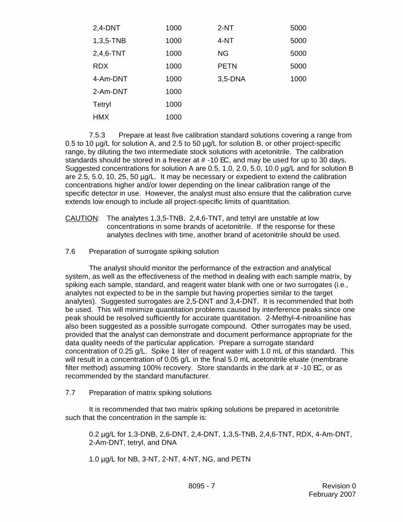
7.5.3 Prepare at least five calibration standard solutions covering a range from0.5 to 10 µg/L for solution A, and 2.5 to 50 µg/L for solution B, or other project-specificrange, by diluting the two intermediate stock solutions with acetonitrile. The calibrationstandards should be stored in a freezer at # -10 EC, and may be used for up to 30 days. Suggested concentrations for solution A are 0.5, 1.0, 2.0, 5.0, 10.0 µg/L and for solution Bare 2.5, 5.0, 10, 25, 50 µg/L. It may be necessary or expedient to extend the calibrationconcentrations higher and/or lower depending on the linear calibration range of thespecific detector in use. However, the analyst must also ensure that the calibration curveextends low enough to include all project-specific limits of quantitation.
CAUTION: The analytes 1,3,5-TNB, 2,4,6-TNT, and tetryl are unstable at lowconcentrations in some brands of acetonitrile. If the response for theseanalytes declines with time, another brand of acetonitrile should be used.
7.6 Preparation of surrogate spiking solution
The analyst should monitor the performance of the extraction and analyticalsystem, as well as the effectiveness of the method in dealing with each sample matrix, byspiking each sample, standard, and reagent water blank with one or two surrogates (i.e.,analytes not expected to be in the sample but having properties similar to the targetanalytes). Suggested surrogates are 2,5-DNT and 3,4-DNT. It is recommended that bothbe used. This will minimize quantitation problems caused by interference peaks since onepeak should be resolved sufficiently for accurate quantitation. 2-Methyl-4-nitroaniline hasalso been suggested as a possible surrogate compound. Other surrogates may be used,provided that the analyst can demonstrate and document performance appropriate for thedata quality needs of the particular application. Prepare a surrogate standardconcentration of 0.25 g/L. Spike 1 liter of reagent water with 1.0 mL of this standard. Thiswill result in a concentration of 0.05 g/L in the final 5.0 mL acetonitrile eluate (membranefilter method) assuming 100% recovery. Store standards in the dark at # -10 EC, or asrecommended by the standard manufacturer.
7.7 Preparation of matrix spiking solutions
It is recommended that two matrix spiking solutions be prepared in acetonitrilesuch that the concentration in the sample is:
0.2 µg/L for 1,3-DNB, 2,6-DNT, 2,4-DNT, 1,3,5-TNB, 2,4,6-TNT, RDX, 4-Am-DNT,2-Am-DNT, tetryl, and DNA
1.0 µg/L for NB, 3-NT, 2-NT, 4-NT, NG, and PETN
8095 - 8 Revision 0February 2007
2.0 µg/L for HMX
All target analytes for a given project should be included in the matrix spiking solutions. Because RDX and PETN co-elute on the DB-1 column, these analytes should be inseparate spiking solutions (A and B) when the DB-1 column is employed. Follow thesame guidance outlined in Secs. 7.5.1 and 7.5.2 to determine what analytes to include inwhich matrix spiking solution. It would be expected that the same analytes in thecalibration standard(s) are also present in the matrix spike standard(s). Store standards inthe dark at # -10 EC, or as recommended by the standards manufacturer.
8.0 SAMPLE COLLECTION, PRESERVATION, AND STORAGE
8.1 See the introductory material to Chapter Four, "Organic Analytes."
8.2 Sample extracts should be stored in the dark at #6 EC.
8.3 Soil samples may be contaminated, and should therefore be considered hazardousand handled accordingly. See Sec. 5.0 for additional safety considerations.
9.0 QUALITY CONTROL
9.1 Refer to Chapter One for guidance on quality assurance (QA) and quality control(QC) protocols. When inconsistencies exist between QC guidelines, method-specific QCcriteria take precedence over both technique-specific criteria and those criteria given in ChapterOne, and technique-specific QC criteria take precedence over the criteria in Chapter One. Anyeffort involving the collection of analytical data should include development of a structured andsystematic planning document, such as a Quality Assurance Project Plan (QAPP) or a Samplingand Analysis Plan (SAP), which translates project objectives and specifications into directionsfor those that will implement the project and assess the results. Each laboratory shouldmaintain a formal quality assurance program. The laboratory should also maintain records todocument the quality of the data generated. All data sheets and quality control data should bemaintained for reference or inspection.
9.2 Refer to Method 8000 for specific determinative method QC procedures. Refer toMethod 3500 for QC procedures to ensure the proper operation of the various samplepreparation techniques. If an extract cleanup procedure is performed, refer to Method 3600 forthe appropriate QC procedures. Any more specific QC procedures provided in this method willsupersede those noted in Methods 8000, 3500, or 3600.
9.3 Quality control procedures necessary to evaluate the GC system operation arefound in Method 8000 and include evaluation of retention time windows, calibration verificationand chromatographic analysis of samples.
9.4 Initial demonstration of proficiency
Each laboratory must demonstrate initial proficiency with each sample preparation anddeterminative method combination it utilizes by generating data of acceptable accuracy andprecision for target analytes in a clean matrix. If an autosampler is used to perform sampledilutions, before using the autosampler to dilute samples, the laboratory should satisfy itself thatthose dilutions are of equivalent or better accuracy than is achieved by an experienced analystperforming manual dilutions. The laboratory must also repeat the demonstration of proficiency

8095 - 9 Revision 0February 2007
whenever new staff members are trained or significant changes in instrumentation are made. See Method 8000 for information on how to accomplish a demonstration of proficiency.
9.4.1 It is suggested that the spiking solution used to prepare the samples forthis demonstration of proficiency contain each analyte of interest at the concentrationslisted for the matrix spike in Sec. 7.7.
9.4.2 Calculate the average recovery and the standard deviation of therecoveries of the analytes in each of the four QC reference samples. Refer to Method8000 for procedures for evaluating method performance.
9.5 Initially, before processing any samples, the analyst should demonstrate that allparts of the equipment in contact with the sample and reagents are interference-free. This isaccomplished through the analysis of a method blank. As a continuing check, each timesamples are extracted, cleaned up, and analyzed, and when there is a change in reagents, amethod blank should be prepared and analyzed for the compounds of interest as a safeguardagainst chronic laboratory contamination. If a peak is observed within the retention time windowof any analyte that would prevent the determination of that analyte, determine the source andeliminate, if possible, before processing the samples. The blanks should be carried through allstages of sample preparation and analysis. When new reagents or chemicals are received, thelaboratory should monitor the preparation and/or analysis blanks associated with samples forany signs of contamination. It is not necessary to test every new batch of reagents or chemicalsprior to sample preparation if the source shows no prior problems. However, if reagents arechanged during a preparation batch, separate blanks need to be prepared for each set ofreagents.
9.6 Sample quality control for preparation and analysis
The laboratory must also have procedures for documenting the effect of the matrix onmethod performance (precision, accuracy, method sensitivity). At a minimum, this shouldinclude the analysis of QC samples including a method blank, a matrix spike, a duplicate, and alaboratory control sample (LCS) in each analytical batch and the addition of surrogates to eachfield sample and QC sample when surrogates are used. Any method blanks, matrix spikesamples, and replicate samples should be subjected to the same analytical procedures (Sec.11.0) as those used on actual samples.
9.6.1 Documenting the effect of the matrix should include the analysis of atleast one matrix spike and one duplicate unspiked sample or one matrix spike/matrix spikeduplicate pair. The decision on whether to prepare and analyze duplicate samples or amatrix spike/matrix spike duplicate must be based on a knowledge of the samples in thesample batch. If samples are expected to contain target analytes, laboratories may use amatrix spike and a duplicate analysis of an unspiked field sample. If samples are notexpected to contain target analytes, the laboratories should use a matrix spike and matrixspike duplicate pair. Consult Method 8000 for information on developing acceptancecriteria for the MS/MSD
Note: The compounds in solution A (see Sec. 7.5.2) are more commonly found atarsenals that work with the finished product. Therefore, unless the site is expectedto contain compounds found in solution B, use the compounds in solution A toprepare routine matrix spike/matrix spike duplicate pairs (see Sec. 7.7).
9.6.2 A laboratory control sample (LCS) should be included with each analyticalbatch. The LCS consists of an aliquot of a clean (control) matrix similar to the samplematrix and of the same weight or volume. The LCS is spiked with the same analytes at

8095 - 10 Revision 0February 2007
the same concentrations as the matrix spike, when appropriate. When the results of thematrix spike analysis indicate a potential problem due to the sample matrix itself, the LCSresults are used to verify that the laboratory can perform the analysis in a clean matrix. Consult Method 8000 for information on developing acceptance criteria for the LCS.
9.6.3 Also see Method 8000 for the details on carrying out sample qualitycontrol procedures for preparation and analysis. In-house method performance criteria forevaluating method performance should be developed using the guidance found in Method8000.
9.7 Surrogate recoveries
If surrogates are used, the laboratory should evaluate surrogate recovery data fromindividual samples versus the surrogate control limits developed by the laboratory. See Method8000 for information on evaluating surrogate data and developing and updating surrogate limits. Procedures for evaluating the recoveries of multiple surrogates and the associated correctiveactions should be defined in an approved project plan.
9.8 It is recommended that the laboratory adopt additional quality assurance practicesfor use with this method. The specific practices that are most productive depend upon theneeds of the laboratory and the nature of the samples. Whenever possible, the laboratoryshould analyze standard reference materials and participate in relevant performance evaluationstudies.
10.0 CALIBRATION AND STANDARDIZATION
See Sec. 11.3 for information on calibration and standardization.
11.0 PROCEDURE
11.1 Sample extraction
Procedures for sample extraction of aqueous and solid samples are providedelsewhere in this manual. Methods other than those recommended below may be used,provided that they can be demonstrated to perform adequately for the intendedapplication.
11.1.1 Consult Method 3535 for the solid-phase extraction procedures utilizingeither SPE cartridges or SPE disks.
11.1.2 Consult Method 8330 for an ultrasonic procedure for the extraction of soiland solid waste samples.
CAUTION: When performing ultrasonic extraction of explosives, it is important to keepthe ultrasonic bath at or below ambient laboratory temperature, in order tominimize the thermal degradation of the analytes of interest. This may beaccomplished by several means, including by placing a cooling coil in thebath.
11.1.3 Store sample extracts in the freezer until analysis.
8095 - 11 Revision 0February 2007
11.2 Sample analysis by GC/ECD
11.2.1 Sample extracts must be kept refrigerated at all times, in order tominimize the degradation of the analytes of interest. If an autosampler is used, it must becapable of refrigerating the vials (see Sec. 6.3) at #6 EC. When using an autosampler,allow the sample extracts to equilibrate to the temperature of the autosampler tray beforebeginning analyses. If manual injections are used, keep the extracts refrigerated until justbefore the injection is made.
11.2.2 Deactivate the GC column if the GC has not been used during the pastday or so (see Sec. 11.3.4).
11.2.3 Perform initial calibration (Sec. 11.3.6) or calibration verification (Sec.11.3.7). Beginning an analysis run with calibration verification is acceptable if thecalibration verification criterion can still be met. Subsequent calibration verificationincludes the analysis of additional calibration standards interspersed with sample extracts(see Sec. 11.3.7). Consult Method 8000 for approaches to initial calibration andcalibration verification.
11.2.4 Inject about 1 µL of the sample extract into the GC and record the exactvolume injected. The same GC operating conditions used for the initial calibration must beemployed for the analysis of samples.
11.2.5 Sample injections may continue for as long as the calibration verificationstandards and the standards interspersed with the samples meet instrument QC criteria(see Sec. 11.3.7).
11.3 Calibration of GC
11.3.1 The GC column should be baked at the injection port temperature untilthe baseline is stable. (The injection port temperature should not be set higher then themaximum column temperature recommended by the column manufacturer.)
NOTE: Because of the thermal lability of some of these analytes, reliable quantitation is very dependent on the condition of the GC system. The injection port and column shouldalways be cleaned prior to performing the initial calibration. This is especially true forthe nitramines and for HMX in particular.
11.3.2 Prepare calibration standards as described in Sec. 7.5. All standardsshould be kept refrigerated at all times, including while the standards are in theautosampler. If a refrigerated autosampler is used, it should be maintained at #6 EC. Ifmanual injections are used, keep the standards refrigerated until just before the injection ismade.
CAUTION: The compounds 1,3,5-TNB, 2,4,6-TNT and tetryl are unstable at lowconcentrations in some brands of acetonitrile. If the responses for these analytesdecline with time, another brand of acetonitrile should be used.
11.3.3 Establish the GC operating conditions appropriate for the GC columnbeing utilized and the target analytes listed in the project plan. Optimize the instrumentalconditions for resolution of the target analytes and sensitivity. Suggested operatingconditions are given below for the columns recommended in Sec. 6.2. Table 1 presentsexamples of analyte retention times at different linear velocities for some of the primaryand confirmation columns. Figures 1 through 3 illustrate the potential effects of flow rate

8095 - 12 Revision 0February 2007
on the separation and retention times of the target analytes. Use these figures asguidance in selecting the appropriate linear velocity for the target analytes in the projectplan. If all target analytes are to be included, then the lowest linear velocity isrecommended.
NOTE: Once established, the same operating conditions must be used for both calibrationsand sample analyses.
11.3.3.1 Suggested GC operating conditions for the recommendedprimary columns
HP-5 column
Injection Port Temperature: 250 EC
Injection volume: 1 µL
Carrier gas: Hydrogen (flow rate 15 mL/min)
Makeup gas: Nitrogen (flow rate 30 mL/min)
Detector temperature: 300 EC
Temperature Program
Initial temperature: 100 EC for 2 min
1st temperature ramp: 10 EC per min to 200 EC
2nd temperature ramp: 20 EC per min to 250 EC
Final hold: 5.5 min
DB-1 column
Injection Port Temperature: 250 EC
Injection volume: 1 µL
Carrier gas: Hydrogen (linear velocity 40-125cm/sec)
Makeup gas: Nitrogen (flow rate 38 mL/min)
Detector temperature: 300EC
Temperature Program
Initial temperature: 100EC for 2 min
1st temperature ramp: 10 EC per min to 200 EC
2nd temperature ramp: 20 EC per min to 250 EC
Final hold: 5 min
NOTE: Peak resolution is greatest at low linear velocity, but GC response for someanalytes is greatest at high linear velocity (see Table 2). The linear velocityshould be chosen based on the objectives of the analysis. A mid-range linearvelocity of about 80 cm/s will be suitable for most analyses unless nitrobenzeneand the nitrotoluenes are to be included and solvent peak broadening interferes.

8095 - 13 Revision 0February 2007
NOTE: Other carrier gases used routinely with an ECD are acceptable. However, theuse of hydrogen provides the best peak resolution. The retention times,chromatograms, and data presented in this method were developed withhydrogen.
11.3.3.2 Suggested GC operating conditions for the recommendedconfirmation columns
RTX-200 column (low linear velocity option)
Injection Port Temperature: 250 EC
Injection volume: 1 µL
Carrier gas: Hydrogen (linear velocity 40 cm/sec)
Detector temperature: 290 EC
Temperature Program
Initial temperature: 100 EC for 1.2 min
1st temperature ramp: 5 EC per min to 140 EC
2nd temperature ramp: 1 EC per min to 160 EC
3rd temperature ramp: 20 EC per min to 250 EC
RTX-200 column (high linear velocity option)
Injection Port Temperature: 270 EC
Injection volume: 1 µL
Carrier gas: Hydrogen (linear velocity 122 cm/sec)
Detector temperature: 290 EC
Temperature Program
Initial temperature: 150 EC for 1 min
Temperature ramp: 20 EC per min to 250 EC and hold
RTX-225
Injection Port Temperature: 220 EC
Injection volume: 1 µL
Carrier gas: Hydrogen (linear velocity 108 cm/sec)
Detector temperature: 250 EC
Temperature Program
Initial temperature: 100 EC for 2 min
Temperature ramp: 10 EC per min to 220 EC
Final hold: 8 min
11.3.4 Because of the low concentration of standards injected on a GC/ECD,column adsorption may be a problem when the GC has not been used for a day or more.
8095 - 14 Revision 0February 2007
Therefore, the GC column should be primed (or deactivated) by injecting a standardmixture approximately 20 times more concentrated than the mid-concentration standard. Inject this standard mixture prior to beginning the initial calibration or calibrationverification.
11.3.5 A 1-µL injection volume of each calibration standard is recommended.
11.3.6 Initial calibration
Inject each of the calibration standards, in order from lowest to highestconcentration, and obtain peak heights or peak areas for each analyte. Follow thecalibration procedures outlined in Method 8000. Normally, since this is an ECDmethod, external standard calibration is used along with the linear calibrationmodel. However, other calibration models may be used, as appropriate. Calculatecalibration factors (CFs) and ensure that all target analytes meet the recommendedcalibration criterion of #20% RSD, or other criteria appropriate for the specificproject.
11.3.7 Calibration verification
11.3.7.1 See Method 8000 for detailed instructions on calibrationverification. Include a mid-level calibration standard after each group of 20samples in the analysis sequence as a calibration check. (It is recommended thata calibration standard be included after every 10 samples to minimize the numberof repeat injections). Injections of method blanks, matrix spike samples, and othernon-standards are counted in the total. Solvent blanks, injected as a check oncross-contamination, need not be counted in the total. If all target analytes areincluded in a given project, it will be necessary to inject two calibration standards inorder to verify the calibration of all the analytes. If the injection of both calibrationstandards is necessary, alternate the two calibration standards by injecting one setafter the first ten samples and the second set after the second 10 samples.
NOTE: As mentioned in Sec. 7.5.1, two calibration standards are used becauseDNA and 4-Am-DNT coelute on both the HP-5 and the DB-1 columns andRDX and PETN co-elute on the DB-1 column. These coelutingcompounds may be reported as the total of two compounds, unless oneof the compounds is known not to be present at a site.
11.3.7.2 If there has been a break in analyses since initial calibrationwas performed, begin by injecting a mid-level calibration standard containing thetarget analytes. As noted above, the injection of two calibration standards may beneeded. Ensure that the recommended calibration verification criterion of ±20% ismet before beginning the injection of samples. If the results for the verificationstandard are close to the control limits, it is highly recommended that injection portand column maintenance be performed and the verification standard besuccessfully reanalyzed prior to proceeding with sample injections. This should bedone to avoid having to reinject all samples if the next calibration verificationstandard exceeds the criterion. This is especially true if HMX is a target analyteand is close to exceeding control limits.
11.3.7.3 The calibration factors for the verification should be within±20% of the mean calibration factors from the initial calibration (see Sec. 11.0 ofMethod 8000 for more details). When this calibration verification standard falls out

8095 - 15 Revision 0February 2007
of this acceptance window, the laboratory should stop analyses and take correctiveaction as outlined in Method 8000, and recalibrate, if necessary.
11.3.7.4 If quantitation is accomplished using an internal standard,internal standards must be evaluated for acceptance. The measured area of theinternal standard must be no more than 50 percent different from the average areacalculated during calibration. When the internal standard peak area is outside thelimit, all samples that fall outside the QC criterion must be reanalyzed or the datamust be treated as estimated.
11.3.8 Retention time windows -- Absolute retention times are used forcompound identification. Retention time windows are crucial to the identification of targetcompounds, and should be established by one of the approaches described in Method8000.
11.3.8.1 Before establishing the retention time windows, make sure thegas chromatographic system is operating within optimum conditions.
11.3.8.2 The widths of the retention time windows are defined asdescribed in Method 8000. However, the experience of the analyst should weighheavily in the interpretation of the chromatograms.
11.4 GC analysis
11.4.1 Compare the retention time of each analyte in the calibration standardwith the absolute retention time windows established in Sec. 11.3.8. As described inMethod 8000, the center of the absolute retention time window for each analyte is itsretention time in the mid-concentration standard analyzed during the initial calibration. Each analyte in each standard must fall within its respective retention time window. If not,the gas chromatographic system must either be adjusted so that a second analysis of thestandard does result in all analytes falling within their retention time windows, or a newinitial calibration must be performed and new retention time windows established.
11.4.2 Tentative identification of an analyte occurs when a peak from a sampleextract falls within the absolute retention time window. Each tentative identification shouldbe confirmed using either a second GC column of dissimilar stationary phase or usinganother technique such as GC/MS or HPLC/UV (see Method 8000, Sec. 11.0).
11.4.3 For the options on reporting confirmation results, see Sec. 11.0 of Method8000.
11.4.4 For guidance on verification of external standard calibrations, see Sec.11.3.7 of this method and see Method 8000. When performing external standardcalibration and a calibration verification standard fails to meet the QC criteria, all samplesthat were injected after the last standard that last met the QC criteria must be evaluated toprevent misquantitations and possible false negative results. Reinjection of the sampleextracts may be needed. More frequent analyses of standards will minimize the number ofsample extracts that would have to be reinjected if the QC limits are violated for thestandard analysis.
However, if the standard analyzed after a group of samples exhibits a response foran analyte that is above the acceptance limit, i.e., >20%, and the analyte was not detectedin the specific samples analyzed during the analytical shift, then the extracts for thosesamples do not need to be reanalyzed, as the verification standard has demonstrated that
8095 - 16 Revision 0February 2007
the analyte would have been detected if it were present. In contrast, if an analyte abovethe QC limits was detected in a sample extract, then reinjection is necessary to ensureaccurate quantitation. If an analyte was not detected in the sample and the standardresponse is more than 20% below the initial calibration response, then reinjection isnecessary to ensure that the detector response has not deteriorated to the point that theanalyte would not have been detected even though it was present (i.e., a false negativeresult).
11.4.5 The target compounds in this method are known to decompose if theinjection port of the GC becomes activated. Therefore, when a calibration verificationstandard fails, the analyst must evaluate whether the calibration has drifted out of theacceptable range due to normal calibration drift or active sites in the injection port causingdegradation of the target compounds. Degradation of the target compounds would beexpected to lead to lower responses.
When reviewing the results of the calibration verification standard, the analystshould keep in mind the number of samples run and/or whether some very dirty samplesmay have contaminated the injection port. As noted in Sec. 4.3, the injection port linermust be deactivated again or a commercially-available deactivated liner should beinserted each time the septum is replaced or at least after every 50 injections.
11.4.6 For guidance on calculating results from internal and external standardcalibrations, see Method 8000. The nominal final extract volumes are 4.0 mL for thecartridge SPE method and 5.0 mL for the disk SPE method, unless the eluate wasconcentrated further. For proper quantitation, the appropriate selection of a baseline fromwhich the peak area or height can be determined is needed.
11.4.7 As mentioned in Sec. 7.5.1, DNA and 4-Am-DNT coelute on both the HP-5 and the DB-1 columns and RDX and PETN co-elute on the DB-1 column. Thesecoeluting compounds may be reported as the total of two compounds, unless one of thecompounds is known not to be present at a site.
12.0 DATA ANALYSIS AND CALCULATIONS
12.1 See Method 8000 for information regarding data analysis and calculations.
12.2 Results need to be reported in units commensurate with their intended use and alldilutions need to be taken into account when computing final results.
13.0 METHOD PERFORMANCE
13.1 Performance data and related information are provided in SW-846 methods only asexamples and guidance. The data do not represent required performance criteria for users ofthe methods. Instead, performance criteria should be developed on a project-specific basis,and the laboratory should establish in-house QC performance criteria for the application of thismethod. These performance data are not intended to be and must be used as absolute QCacceptance criteria for purposes of laboratory accreditation.
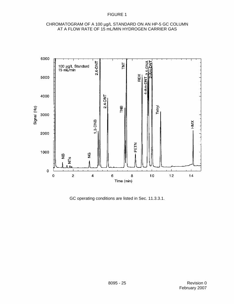
13.2 Tables 1 and 2 present example retention times and calibration factors obtained onvarious GC columns and using several different carrier gas velocities. Example chromatogramsare presented in Figures 1 through 3 (Reference 3). These data are provided for guidancepurposes only.

8095 - 17 Revision 0February 2007
13.3 Using the disk and cartridge SPE procedures outlined in Method 3535, single-laboratory lower limits of detection for the analytes in solution A (Sec. 7.5.2) ranged fromapproximately 0.003 to 0.02 µg/L, based on a spiked sample concentration of 0.01 µg/L. Forthe analytes in solution B, the lower limits of detection ranged from approximately 0.2 to 0.5µg/L for the analytes spiked at 1 µg/L, and was approximately 0.06 µg/L for 3,5-DNA, which wasspiked at 0.2 µg/L. These data are provided for guidance purposes only.
13.4 Table 3 presents single-laboratory recovery and precision data for the analytesspiked into 500 mL of reagent water. Extraction was by the disk SPE method (see Reference3). These data are provided for guidance purposes only.
13.5 Single-laboratory lower limits of detection were determined for spiked soil samplesprepared in two different soil matrices. Lower limits of detection ranged from approximately 0.7to 3.5 µg/kg for analytes spiked at 5 µg/kg, and from approximately 10 to 25 µg/kg for analytesspiked at 50 µg/kg. These data are provided for guidance purposes only.
13.6 Table 4 presents single-laboratory recovery and precision data for the analytesspiked into two different soil matrices. Extraction was performed by the procedure described inMethod 8330. These data are provided for guidance purposes only.
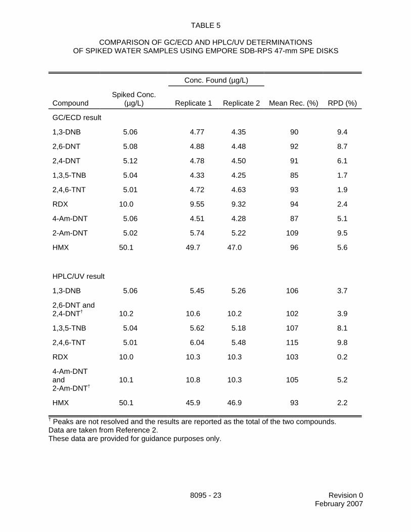
13.7 Tables 5 and 6 present data on the recovery and repeatability of GC/ECD andHPLC/UV determinations of the analyte concentrations in spiked water samples. The HPLCconditions were those found in Method 8330. The samples were extracted as described inMethod 3535 and the extracts were split for GC and HPLC analysis. The analytes in this studyrepresent those most commonly found at arsenals around the country. Data from the disk SPEmethod are presented in Table 5 and data from the cartridge SPE method are presented inTable 6 (see Reference 2). These data are provided for guidance purposes only.
14.0 POLLUTION PREVENTION
14.1 Pollution prevention encompasses any technique that reduces or eliminates thequantity and/or toxicity of waste at the point of generation. Numerous opportunities for pollutionprevention exist in laboratory operations. The EPA has established a preferred hierarchy ofenvironmental management techniques that places pollution prevention as the managementoption of first choice. Whenever feasible, laboratory personnel should use pollution preventiontechniques to address their waste generation. When wastes cannot be feasibly reduced at thesource, the Agency recommends recycling as the next best option.
14.2 For information about pollution prevention that may be applicable to laboratoriesand research institutions consult Less is Better: Laboratory Chemical Management for WasteReduction available from the American Chemical Society's Department of GovernmentRelations and Science Policy, 1155 16th St., N.W. Washington, D.C. 20036, http://www.acs.org.
14.3 This method conforms with the USEPA's pollution prevention goals. The cartridgeSPE method uses only 34 mL of acetonitrile per sample and the disk SPE method only uses 45mL of solvent.
15.0 WASTE MANAGEMENT
The Environmental Protection Agency requires that laboratory waste managementpractices be conducted consistent with all applicable rules and regulations. The Agency urgeslaboratories to protect the air, water, and land by minimizing and controlling all releases from
8095 - 18 Revision 0February 2007
hoods and bench operations, complying with the letter and spirit of any sewer discharge permitsand regulations, and by complying with all solid and hazardous waste regulations, particularlythe hazardous waste identification rules and land disposal restrictions. For further informationon waste management, consult The Waste Management Manual for Laboratory Personnelavailable from the American Chemical Society at the address listed in Sec. 14.2.
16.0 REFERENCES
1. M. Hable, C. Stern, C. Asowata, and K. Williams, "The Determination of Nitroaromaticsand Nitramines in Ground and Drinking Water by Wide-Bore Capillary GasChromatography," Journal of Chromatographic Science, 29:131-135 (1991).
2. M. E. Walsh and T. Ranney, "Determination of Nitroaromatic, Nitramine, and Nitrate EsterExplosives in Water using Solid-phase Extraction and Gas Chromatography-electronCapture Detection: Comparison with High-performance Liquid Chromatography," Journalof Chromatographic Science, 36, pp. 406-416 (1998).
3. M. E. Walsh and T. Ranney, "Determination of Nitroaromatic, Nitramine, and Nitrate EsterExplosives in Water Using SPE and GC-ECD: Comparison with HPLC," CRREL Report98-2. U.S. Army Cold Regions Research and Engineering Laboratory, Hanover, NH(1998).
17.0 TABLES, DIAGRAMS, FLOWCHARTS AND VALIDATION DATA
The following pages contain the tables and figures referenced by this method.

8095 - 19 Revision 0February 2007
TABLE 1
EXAMPLE RETENTION TIMES FOR VARIOUS GC COLUMNSOBTAINED AT DIFFERENT CARRIER GAS LINEAR VELOCITIES
Retention Time (min)
DB-1 Column RTX-200 Column RTX-225 Column
Compound LV = 126 LV = 44 LV = 40 LV = 122 LV = 108
NB 0.32 1.38 2.15 ES ND
2-NT 0.47 2.06 2.78 ES 0.95
3-NT 0.57 2.47 3.40 ES 1.20
4-NT 0.62 2.69 3.72 ES 1.40
NG 1.18 3.84 8.57 0.52 6.25
1,3-DNB 1.84 5.05 9.01 0.63 5.86
2,6-DNT 2.07 5.28 8.51 0.55 5.50
2,4-DNT 2.88 6.12 10.64 0.88 6.51
1,3,5-TNB 4.19 7.42 18.90 1.98 9.99
2,4,6-TNT 4.61 7.82 17.81 1.86 9.51
PETN 5.62 8.79 28.52 2.74 11.57
RDX 5.62 8.83 29.19 2.86 13.66
4-Am-DNT 6.77 9.92 23.80 2.45 12.65
3,5-DNA 6.83 10.07 26.08 2.65 13.32
2-Am-DNT 7.17 10.38 28.57 2.85 13.17
Tetryl 8.05 11.26 32.11 3.54 13.65
HMX 11.21 13.92 not eluted 6.29 not eluted
surr = SurrogateLV = Linear Velocity in cm/sES = Elutes in solvent peakND =- Not DeterminedData are taken from Reference 3Chromatographic conditions are described in Sec. 11.3.3All data are provided as examples only. Each laboratory must determine retention timesand retention time windows for their specific application of the method.

8095 - 20 Revision 0February 2007
TABLE 2
EXAMPLE CALIBRATION FACTORS OBTAINED AT DIFFERENT CARRIER GASLINEAR VELOCITIES USING A DB-1 COLUMN AND 50 µg/L SOLUTIONS
Calibration Factor
Compound LV = 126 cm/s LV = 44 cm/s
2,4,6-TNT 104 109
2,6-DNT 91 92
2-Am-DNT 80 83
RDX 79 52
HMX 75 32
4-Am-DNT 71 76
DNA 69 69
2,4-DNT 58 58
Tetryl 46 59
1,3,5-TNB 45 50
1,3-DNB 30 28
NB 18 9.9
PETN 17 8.1
NG 12 4.5
3-NT 7.5 7.4
2-NT 5.9 3.6
4-NT 2.5 4.5
The calibration factor is calculated as the peak height divided by the concentration of thestandard. All data are provided as examples only. Each laboratory must determine calibrationfactors for their specific application of the method.
Data are taken from Reference 3.

8095 - 21 Revision 0February 2007
TABLE 3
RECOVERY OF TARGET ANALYTES FROM WATER USING DISK SPE PROCEDURES
Compound Spike Conc. (µg/L) Mean Recovery (%) RSD(%)
1,3-DNB 0.2 99 9.7
2,6-DNT 0.2 93 7.1
2,4-DNT 0.2 104 7.6
1,3,5-TNB 0.2 94 7.7
2,4,6-TNT 0.2 116 8.0
RDX 0.2 88 7.2
4-Am-DNT 0.2 75 11.2
2-AM-DNT 0.2 87 11.6
Tetryl 0.2 95 8.3
DNA 0.2 74 9.2
NB 1 97 7.1
2-NT 1 93 5.1
3-NT 1 92 4.6
4-NT 1 90 5.3
NG 1 92 5.5
PETN 1 99 4.8
HMX 2 79 8.1
Mean recovery from seven replicate 500-mL water samples extracted using Empore SDB-RPSdisks and with a final volume of 5 mL of acetonitrile.
Data are taken from Reference 3.These data are provided for guidance purposes only.
8095 - 22 Revision 0February 2007
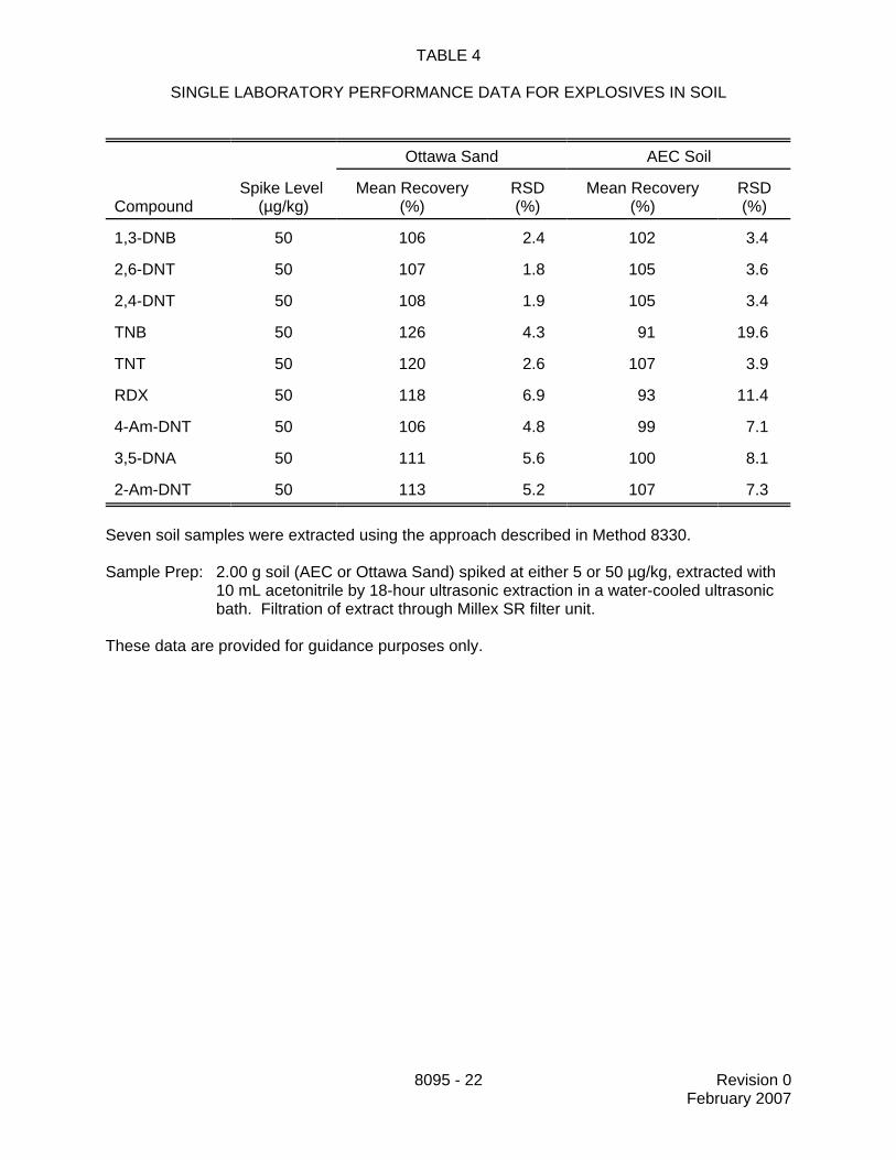
TABLE 4
SINGLE LABORATORY PERFORMANCE DATA FOR EXPLOSIVES IN SOIL
Ottawa Sand AEC Soil
CompoundSpike Level
(µg/kg)Mean Recovery
(%)RSD(%)
Mean Recovery(%)
RSD(%)
1,3-DNB 50 106 2.4 102 3.4
2,6-DNT 50 107 1.8 105 3.6
2,4-DNT 50 108 1.9 105 3.4
TNB 50 126 4.3 91 19.6
TNT 50 120 2.6 107 3.9
RDX 50 118 6.9 93 11.4
4-Am-DNT 50 106 4.8 99 7.1
3,5-DNA 50 111 5.6 100 8.1
2-Am-DNT 50 113 5.2 107 7.3
Seven soil samples were extracted using the approach described in Method 8330.
Sample Prep: 2.00 g soil (AEC or Ottawa Sand) spiked at either 5 or 50 µg/kg, extracted with10 mL acetonitrile by 18-hour ultrasonic extraction in a water-cooled ultrasonicbath. Filtration of extract through Millex SR filter unit.
These data are provided for guidance purposes only.
8095 - 23 Revision 0February 2007
TABLE 5
COMPARISON OF GC/ECD AND HPLC/UV DETERMINATIONSOF SPIKED WATER SAMPLES USING EMPORE SDB-RPS 47-mm SPE DISKS
Conc. Found (µg/L)
CompoundSpiked Conc.
(µg/L) Replicate 1 Replicate 2 Mean Rec. (%) RPD (%)
GC/ECD result
1,3-DNB 5.06 4.77 4.35 90 9.4
2,6-DNT 5.08 4.88 4.48 92 8.7
2,4-DNT 5.12 4.78 4.50 91 6.1
1,3,5-TNB 5.04 4.33 4.25 85 1.7
2,4,6-TNT 5.01 4.72 4.63 93 1.9
RDX 10.0 9.55 9.32 94 2.4
4-Am-DNT 5.06 4.51 4.28 87 5.1
2-Am-DNT 5.02 5.74 5.22 109 9.5
HMX 50.1 49.7 47.0 96 5.6
HPLC/UV result
1,3-DNB 5.06 5.45 5.26 106 3.7
2,6-DNT and 2,4-DNT† 10.2 10.6 10.2 102 3.9
1,3,5-TNB 5.04 5.62 5.18 107 8.1
2,4,6-TNT 5.01 6.04 5.48 115 9.8
RDX 10.0 10.3 10.3 103 0.2
4-Am-DNTand 2-Am-DNT†
10.1 10.8 10.3 105 5.2
HMX 50.1 45.9 46.9 93 2.2
† Peaks are not resolved and the results are reported as the total of the two compounds.Data are taken from Reference 2.These data are provided for guidance purposes only.

8095 - 24 Revision 0February 2007
TABLE 6
COMPARISON OF GC/ECD AND HPLC/UV DETERMINATIONS OF SPIKED WATERSAMPLES USING WATERS SEP-PAK RDX SPE CARTRIDGES
Conc. Found (µg/L)
CompoundSpiked Conc.
(µg/L) Replicate 1 Replicate 2 Mean Rec. (%) RPD (%)
GC/ECD result
1,3-DNB 5.06 5.20 4.66 98 11.1
2,6-DNT 5.08 5.29 4.87 100 8.3
2,4-DNT 5.12 5.03 4.80 96 4.6
1,3,5-TNB 5.04 4.92 4.73 96 3.8
2,4,6-TNT 5.01 5.26 5.07 103 3.7
RDX 10.0 10.8 10.6 106 1.8
4-Am-DNT 5.06 5.05 4.58 95 9.6
2-Am-DNT 5.02 5.26 4.85 101 8.1
HMX 50.1 68.8 67.7 136 1.6
HPLC/UV result
1,3-DNB 5.06 5.76 5.70 113 1.1
2,6-DNT and 2,4-DNT† 10.16 11.0 11.0 108 0.3
1,3,5-TNB 5.04 5.71 5.67 113 0.7
2,4,6-TNT 5.01 5.97 5.99 119 0.4
RDX 10.0 12.5 12.1 123 3.3
4-Am-DNTand 2-Am-DNT†
10.1 10.6 10.6 105 0.4
HMX 50.1 55.5 56.2 111 1.3
† Peaks are not resolved and the results are reported as the total of the two compounds.Data are taken from Reference 2.These data are provided for guidance purposes only.
8095 - 25 Revision 0February 2007
FIGURE 1
CHROMATOGRAM OF A 100 µg/L STANDARD ON AN HP-5 GC COLUMNAT A FLOW RATE OF 15 mL/MIN HYDROGEN CARRIER GAS
GC operating conditions are listed in Sec. 11.3.3.1.

8095 - 26 Revision 0February 2007
FIGURE 2
CHROMATOGRAM OF A 100 µg/L STANDARD ON AN HP-5 GC COLUMNAT A FLOW RATE OF 20 mL/MIN HYDROGEN CARRIER GAS
GC operating conditions are listed in Sec. 11.3.3.1. Note the effect of the flow rate on theseparation of 4-Am-DNT and 3,5-DNA , as well as on the retention time of HMX.
8095 - 27 Revision 0February 2007
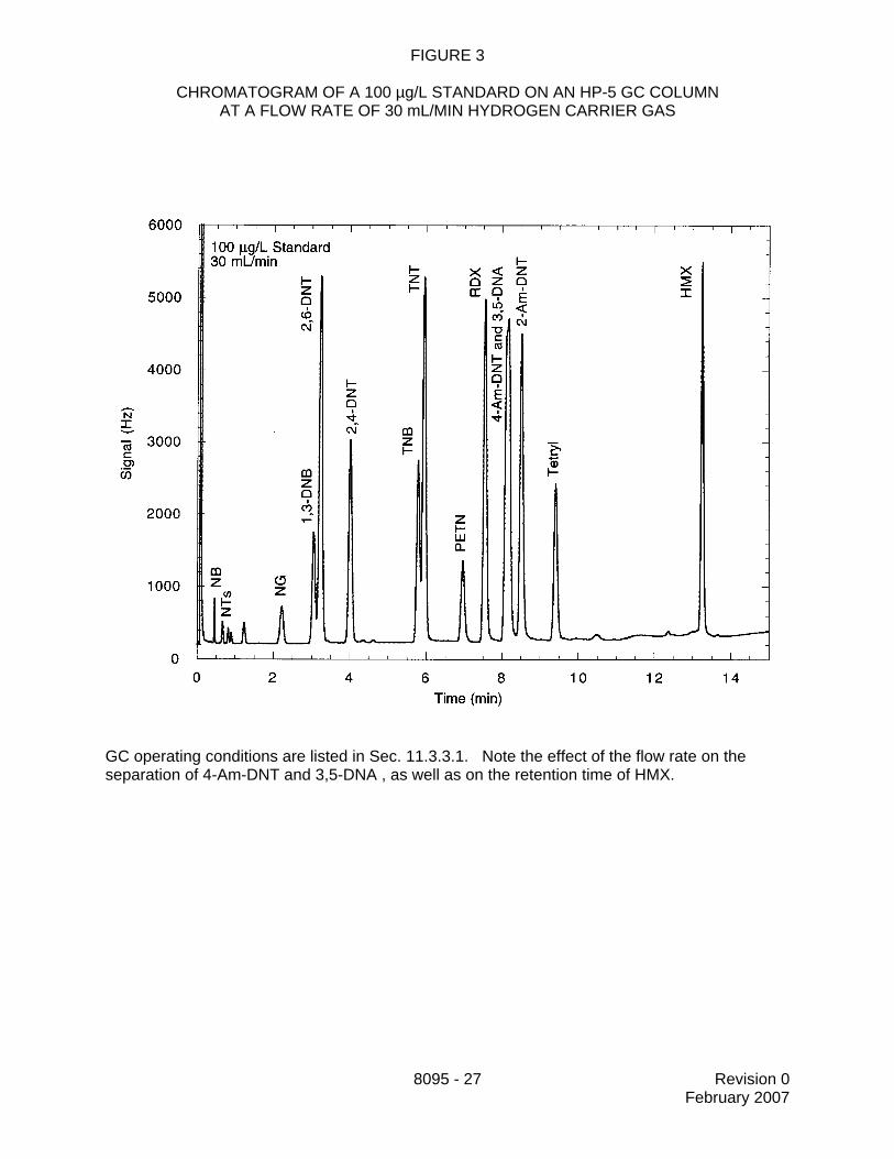
FIGURE 3
CHROMATOGRAM OF A 100 µg/L STANDARD ON AN HP-5 GC COLUMNAT A FLOW RATE OF 30 mL/MIN HYDROGEN CARRIER GAS
GC operating conditions are listed in Sec. 11.3.3.1. Note the effect of the flow rate on theseparation of 4-Am-DNT and 3,5-DNA , as well as on the retention time of HMX.