METHOD 25.1 DETERMINATION OF TOTAL GASEOUS NON …the clamp (Figure 25.1-4) is in the closed...
72
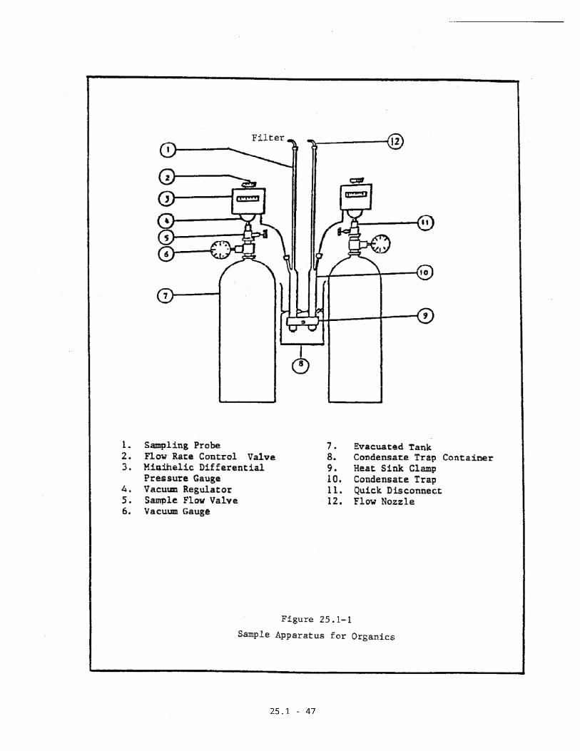
25.1-1 METHOD 25.1 DETERMINATION OF TOTAL GASEOUS NON-METHANE ORGANIC EMISSIONS AS CARBON Section 1 of 5 1. Overview 1.1 Principle Duplicate gas samples are withdrawn from a source at a constant rate through condensate traps immersed in dry ice followed by evacuated 8 liter (nominal) tanks (Figure 25.1-1). Heavy organic components condense as liquids and solids in the condensate traps. Lighter components pass as gases through the traps into the tanks. Volatile Organic Compounds (VOC) as Total Gaseous Non- Methane Organics (TGNMO) are determined by combining results from independent analyses of condensate in the traps and gases in the tanks. These results are used to determine a qualitative and quantitative expression of the effluent gas stream. Duplicate sampling is designed into the system to ensure precision. After sampling is completed, carbon dioxide (CO 2 ) is stripped from the condensate trap and the
Transcript of METHOD 25.1 DETERMINATION OF TOTAL GASEOUS NON …the clamp (Figure 25.1-4) is in the closed...

25.1-1
METHOD 25.1
DETERMINATION OF TOTAL GASEOUS NON-METHANE ORGANIC EMISSIONSAS CARBON
Section 1 of 5
1. Overview
1.1 Principle
Duplicate gas samples are withdrawn from a source
at a constant rate through condensate traps
immersed in dry ice followed by evacuated 8 liter
(nominal) tanks (Figure 25.1-1). Heavy organic
components condense as liquids and solids in the
condensate traps. Lighter components pass as
gases through the traps into the tanks. Volatile
Organic Compounds (VOC) as Total Gaseous Non-
Methane Organics (TGNMO) are determined by
combining results from independent analyses of
condensate in the traps and gases in the tanks.
These results are used to determine a qualitative
and quantitative expression of the effluent gas
stream. Duplicate sampling is designed into the
system to ensure precision.
After sampling is completed, carbon dioxide (CO2)
is stripped from the condensate trap and the

25.1-2
remaining organics are oxidized to CO2. This CO2
is quantitatively collected in an evacuated
vessel and measured by injection into the gas
analysis module of the total combustion analyzer
(TCA) and detected by non-dispersive infrared
(NDIR) detector.
The organic content of the sample fraction
collected in each tank is measured by injecting a
portion into the gas analysis module of the TCA
which uses a GC column to separate the non-
methane organics (NMO) from carbon monoxide (CO),
CO2 and methane (CH4) prior to combusting to
CO2. The NMO are eluted off the column as
"backflush" or "foreflush".
For greater sensitivity (<25 ppm TGNMO), a gas
analysis module using catalytic reduction to CH4
and FID may be substituted for the NDIR based
unit.
TGNMO as CO2 is calculated by summing the values
obtained from analysis of backflush, foreflush
and trap condensate. Since all CO, CH4, and VOC
are oxidized to CO2, to which the NDIR is
specifically sensitized, no response factors to
other compounds need to be determined.

25.1-3
1.2 Applicability
This method measures VOC as TGNMO, expressed as
carbon. In particular, this method is only
applicable to processes that change the
composition and form of organic compounds (e.g.
ovens, afterburners, and combustion processes)
and processes containing organics that cannot be
measured accurately by any other direct detection
method. Sources where organic particulate matter
may be present (e.g. spray booths or hoods
venting paint coaters) either an in-stack
particulate filter must be used or the sampling
nozzle must be pointed downstream. Otherwise,
random particles containing carbon collected from
the gas stream will yield a higher response and
also affect the accuracy and precision of the
results.
The detection limits (as CO2) for CO, CO2, CH4,
and TGNMO are 25 ppm, 50 ppm, 50 ppm, and 25 ppm,
respectively, when non-condensable organics are
not a significant portion of the sample (i.e.
insignificant foreflush and backflush). See
Section 5 for lower detection limits by using an
FID.

25.1-4
Care should be exercised in the combustion of
samples containing high concentrations of
chlorinated compounds to avoid non-combustion or
incomplete combustion. The combustion products
formed are extremely reactive and could seriously
damage the oxidizer tube. The condensate traps
must be eliminated from the sampling apparatus
because of the corrosive products created in
analysis.
This method reports only the concentration of
carbon sampled and not bonded oxygen, hydrogen,
chlorine, or other elements. However, this
method can be used in combination with GC
analysis, or knowledge of the specific VOC
emitted, to obtain the carbon molecular weight
ratio or other compound ratios.

25.1-5
METHOD 25.1
DETERMINATION OF TOTAL GASEOUS NON-METHANE ORGANIC EMISSIONSAS CARBON
Section 2 of 5
2. Field Procedures
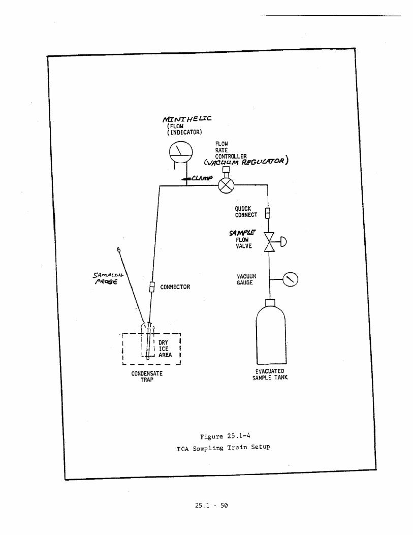
2.1 Sampling Apparatus
The duplicate gas sampling systems consist of
condensate traps, flow controllers, and sample
tanks (Figure 25.1-1). Each system can be
constructed from commercially available
components or components fabricated in a machine
shop. The following components are required for
each system:
a. Probe
Seamless stainless steel tubing, 3.2 mm OD
(1/8 in.) x .66 mm (0.026 in.) wall
thickness.

25.1-6
b. Sample Flow Valve
Stainless steel control valve for starting
and stopping sample flow.
c. Flow Rate Controller
An adjustable vacuum flow regulator
(Variflow) or other system capable of
maintaining the sample rate to within + 10
percent of the selected minihelic _P.
d. Vacuum Gauge
Gauge for monitoring the vacuum of the sample
tank during leak checks and sampling (0 to 30
in. Hg.).
e. Sample Tank
Stainless steel tank with a volume of 8
liters (nominal). Tank volumes must be
calibrated to the nearest 10 ml (see Section
3.9).
25.1-7
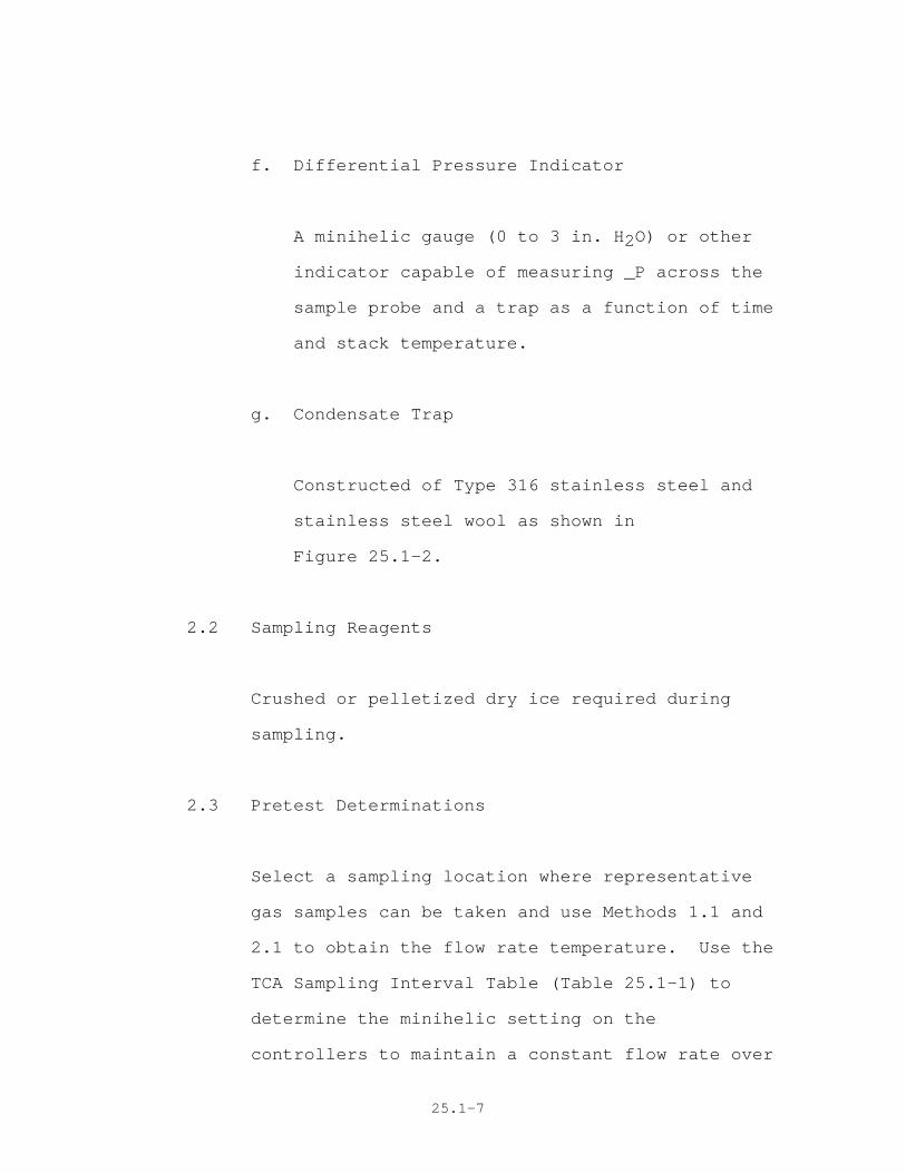
f. Differential Pressure Indicator
A minihelic gauge (0 to 3 in. H2O) or other
indicator capable of measuring _P across the
sample probe and a trap as a function of time
and stack temperature.
g. Condensate Trap
Constructed of Type 316 stainless steel and
stainless steel wool as shown in
Figure 25.1-2.
2.2 Sampling Reagents
Crushed or pelletized dry ice required during
sampling.
2.3 Pretest Determinations
Select a sampling location where representative
gas samples can be taken and use Methods 1.1 and
2.1 to obtain the flow rate temperature. Use the
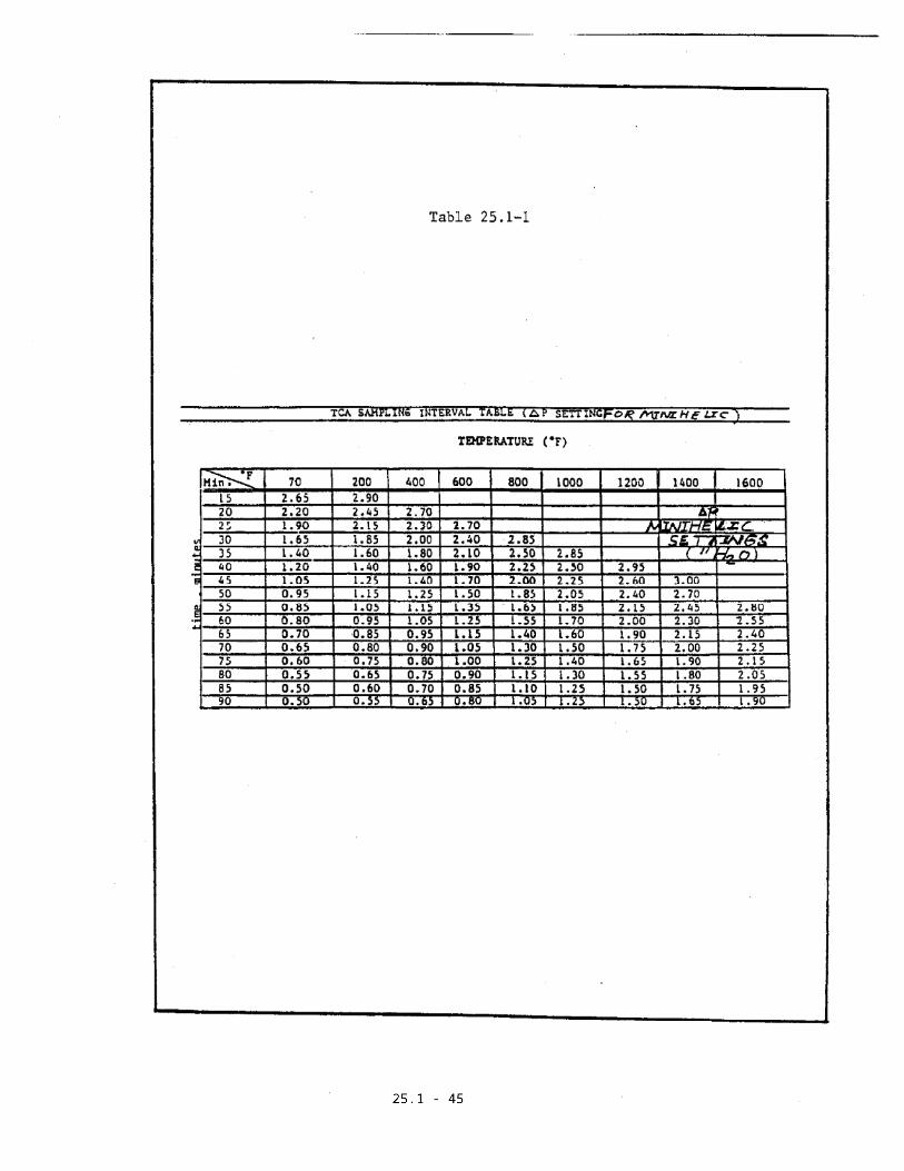
TCA Sampling Interval Table (Table 25.1-1) to
determine the minihelic setting on the
controllers to maintain a constant flow rate over

25.1-8
a sample time interval equal to or greater than
that prescribed. Since this method is not suited
to traversing, the sampling location should be
where the hydrocarbon concentration is uniformly
distributed.
Record identification numbers from condensate
traps, controllers, and evacuated tanks. Record
the vacuum readings from each evacuated tank
gauge (Figure 25.1-3).
2.4 Assembly
Engage the controllers to the evacuated tanks at
their quick-connect fittings. Attach the
condensate traps to the flow controllers.
Important: Keep fittings clean from dust. Use
surgical gloves when touching fittings.
Do not engage a sealed condenser trap/controller
combination to the quick-connect portion of the
evacuated tanks because it may damage the
minihelic gauge and controller.

25.1-9
2.5 Pretest Leak Check
A pretest leak check is required. After
assembling the duplicate gas sampling systems,
assure that each probe tip is tightly plugged and
the clamp (Figure 25.1-4) is in the closed
position to protect its minihelic gauge (flow
indicator). Record the tank vacuum as indicated
by the vacuum gauge and record the barometric
pressure. Open the sample flow valves, wait for
a minimum of 10 minutes, and recheck the
indicated vacuum.
During this waiting period, leak check each
minihelic by following the leak check procedure
outlined in Method 2.1. If the tank vacuum gauge
readings have not changed and the minihelic
gauges are leak-free, the entire duplicate gas
sampling system is considered acceptable. Close
the sample flow valves. Before opening each
clamp at each probe tip, remove the plug to avoid
damaging the minihelic gauges.
If a rotometer and critical flow limiting valve
are used as a flow controller system, the leak
test may be run for only 2 minutes.

25.1-10
2.6 Sampling Operation
Attach flow nozzle to probe end of each trap.
Use soft high temperature wire to secure probe
ends together. Five minutes prior to sampling,
put crushed dry ice in condensate trap container
to within 2.5 to 5 cm of the point where each
inlet tube joins its trap body. Place the probes
into the stack at a preselected point with nozzle
inlet facing downstream of the stack flow. Be
careful not to touch either probe opening against
the stack.
For stacks with a negative or positive static
pressure, insert a static pressure balance tube
into the stack near the sampling point and
connect it to the low pressure side of each
minihelic gauge (see Figure 25.1-5). For stacks
with a negative static pressure, assure the
sample port is sufficiently sealed to prevent air
from leaking in around the probe. Record the
clock time and begin sampling by opening the
sample flow valves. Adjust the flow rate
controller valves (on vacuum regulator) to obtain
the pre-determined minihelic value. End the
sampling when the sample time period has been
25.1-11
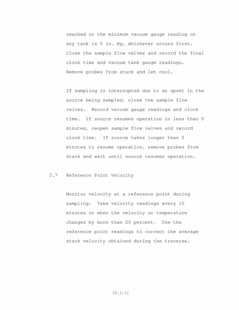
reached or the minimum vacuum gauge reading on
any tank is 5 in. Hg, whichever occurs first.
Close the sample flow valves and record the final
clock time and vacuum tank gauge readings.
Remove probes from stack and let cool.
If sampling is interrupted due to an upset in the
source being sampled, close the sample flow
valves. Record vacuum gauge readings and clock
time. If source resumes operation in less than 5
minutes, reopen sample flow valves and record
clock time. If source takes longer than 5
minutes to resume operation, remove probes from
stack and wait until source resumes operation.
2.7 Reference Point Velocity
Monitor velocity at a reference point during
sampling. Take velocity readings every 10
minutes or when the velocity or temperature
changes by more than 20 percent. Use the
reference point readings to correct the average
stack velocity obtained during the traverse.

25.1-12
2.8 Post Test Leak Check
A leak check is mandatory at the conclusion of
each test run. After sampling is completed,
remove the probe from the stack, remove the
nozzles, plug the probe tips, and close each
clamp. Open the sample flow valve and monitor
the sample tank vacuum gauges for 10 minutes.
The leak check is acceptable if there is no
visible change in the tank vacuum gauge. If the
sampling train does not pass the post leak check,
invalidate the run.
2.9 Disassembly
Close the sample flow valve. Disconnect the
condensate traps at the flow controller and
tightly seal both ends of the condensate traps.
Keep the condensate traps packed in dry ice until
the samples are returned to the laboratory for
analysis.

25.1-13
METHOD 25.1
DETERMINATION OF TOTAL GASEOUS NON-METHANE ORGANIC EMISSIONSAS CARBON
Section 3 of 5
3. Laboratory Procedures
3.1 Apparatus
3.1.1 Sample Collection Train Preparation
a. Probe
3.2 mm OD (1/8 in.) stainless steel
tubing.
b. Sample Flow Valve
Stainless steel control valve for
starting and stopping sample flow.
c. Flow Rate Controller
An adjustable vacuum flow regulator
(Variflow) or other system capable
Administrator

25.1-14
of maintaining the sampling rate to
within + 10 percent of the selected
minihelic ∆P.
d. Vacuum Gauge
Gauge for monitoring the vacuum of the
sample tank during leak checks and
sampling (0 to 30 in. Hg).
e. Sample Tank
Stainless steel tank with a volume of
8 liters (nominal). Tank volumes must
be calibrated to the nearest 10 ml
(see Section 3.9).
f. Differential Pressure Indicator
A minihelic gauge (0 to 3 in. H2O) or
any system that is capable of
indicating the ∆P across the sample
probe and trap as a function of time
and stack temperature.
Administrator
25.1-15
g. Condensate Trap
Constructed of Grade 316 stainless
steel. Construction details of
suitable trap are shown in Figure
25.1-2.
h. Manometer
Must be capable of measuring pressure
to within 1 mm Hg in the 0-900 mm
range. Manometer must be NBS
traceable.
i. Vacuum Pump
Capable of producing a vacuum of <10
mm Hg. This is to evacuate the sample
tanks and intermediate collection
vessels (see Sections 3.3 and 3.4).
25.1-16
3.1.2 Sample Recovery
a. Cryogenic Freezer
Freezer must have the capacity to
store all condensate samples at -80oC
until the sample recovery can be
completed. Storage in dry ice is not
recommended.
b. Heat Source
A heat source sufficient to heat the
condensate trap, including probe, to a
temperature where the trap turns a
"dull red" color. A system using an
electric muffle-type furnace,
electrical clamps for internal
resistance heating, and a Bunsen
burner is recommended.
c. Oxidation System
A system capable of oxidizing CH4 with
an efficiency of at least 95 percent.

25.1-17
d. Water Trap
Any leakproof moisture trap capable of
removing moisture from the gas stream.
e. NDIR Detector
A detector capable of indicating CO2
concentration in the 0 to 1 percent
range. This detector is required for
monitoring the progress of combustion
of the organic from the condensate
trap.
f. Flow Controller
Stainless steel needle valve or mass
flow controller (MFC) required to
maintain the cryogenic trap recovery
system at a near constant gas flow.
g. Intermediate Collection Vessel
Stainless steel or aluminum collection
vessel equipped with female quick-
connect and a pressure-vacuum gauge
(see h. below). Tanks with nominal
25.1-18
volumes in the 1 to 4 liter range are
recommended. Tank volumes must be
calibrated to the nearest 10 ml, (see
Section 3.9).
h. Pressure-Vacuum Gauge
The intermediate collection vessel is
fitted with a gauge capable of
measuring -1 to 0.5 atm.
i. Gas Direction Valve
Valve must be capable of switching
flow through the condensate trap from
a low-oxygen mixture to a high-oxygen
mixture during sample recovery,
without loss of sample or change of
flow rate.
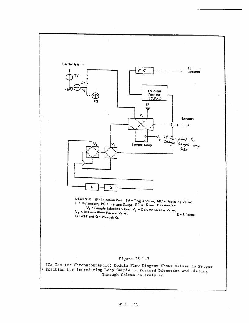
The above components are assembled as
an entire sample recovery system. See
Figures 25.1-6 and 25.1-7 for
assembly.

25.1-19
3.1.3 Sample Analysis
a. Chromatograph
Must be capable of resolving CO, CH4,
and CO2; separating them from the
higher boiling organic compounds; and
have backflush capability (see Section
3.2 Reagents for column types).
Chromatograph must have the capacity
to select between large and small
sample loops.
b. Furnace
Capable of oxidizing CH4, CO, and
organic compounds to CO2 with at least
95 percent efficiency.
c. Non-Dispersive Infrared (NDIR)
Detector
Specific for CO2.

25.1-20
d. Integrator
To sum area under backflush peaks,
which cannot be measured using peak
height.
e. Syringe
100 ml gas-tight.
f. Dewars Flask
Size sufficient to surround the
chromatographic columns.
g. Flow Controller (Optional)
A flow controller capable of
maintaining constant flow to the NDIR
may be necessary.
3.2 Reagents
3.2.1 Sample Collection Train Preparation

25.1-21
a. Compressed nitrogen, 99.9 percent
pure, with THC less than 1 ppm.
3.2.2 Sample Recovery
a. Compressed Nitrogen.
See Section 3.2.1.
b. Carrier Gas
Hydrocarbon-free air. THC less than 1
ppm.
c. Combustion Gas
Zero grade oxygen. 99.6 percent pure.
THC less than 1 ppm.
d. Dry Ice
3.2.3 Sample Analysis
a. Carrier Gas
See Section 3.2.2 b.

25.1-22
b. Chromatographic Columns
The columns used for separating the
various carbon compounds are set in
series as follows:
(1) The initial column is a 1/8 in.
OD column approximately 7 in.
long packed with 10 percent
silicone W-98 oil on Chromosorb
W, 80 to 100 mesh.
(2) The second column is a 1/8 in.
OD x 10 ft long column packed
with Porapak Q, 100 to 200 mesh.
c. Dry Ice
d. 2-Propanol
99.9 percent 2-propanol is used with
dry ice pellets in the ice bath.

25.1-23
e. Water Baths
Water baths at 0oC (ice water), 20oC
(nominal-ambient), and 100oC (boiling
water) are required.
f. Calibration Gases
CO2 in N2 (approximately 2000 ppm,
6000 ppm, and 1 percent); CH4 in N2
(approximately 2000 ppm), calibrated
against an NBS certified CO2 standard
(7 percent).
g. Combustion Gas
See Section 3.2.2 c.
3.3 Pretest Preparation
Before testing, assemble the required equipment
and reagents to check readiness. All analytical,
recovery, and sample equipment must be leak-free
to produce reliable results. Sampling flow
controllers must be flushed with clean air or
nitrogen between test. Sample tanks and

25.1-24
intermediate collection tanks must be evacuated
and filled with nitrogen at least four times
before final evacuation in order to flush
residual hydrocarbons and CO2 from the tanks.
Condensate recovery module should be in the
standby mode to reduce warm-up time.
3.4 Preparation of Sample Collection Train
Evacuate the sample tank to 10 mm Hg absolute
pressure or less (measured by a manometer), then
leak check the sample tank by isolating it from
the vacuum pump and allowing the tank to sit for
at least 10 minutes. The tank is acceptable if
no change in tank vacuum is noted.
Just prior to assembly, measure the tank vacuum
using a manometer. Record this vacuum at this
time. With the flow shutoff valve in the closed
position, assemble the sampling system as shown
in Figure 25.1-1.
3.5 Sample Recovery
3.5.1 Condensate Traps

25.1-25
Keep traps as pairs until analysis of the
traps has begun. Immediately place the
trap pairs in a cryogenic freezer until
sample recovery can be completed.
3.5.2 Tanks
Allow the sampling tanks to equilibrate to
room temperature; then, using a manometer,
measure the pressure of each sample to the
nearest 1 mm Hg. After recording the
initial pressure of the bulb or tank,
pressurize with 99.9 percent N2 to a
pressure between 860-910 mm Hg. Shut off
pressure, wait until reading is stable,
record the reading, and then seal
container until ready for analysis.
3.6.2 Condensate Recovery
3.5.2.1 Condensate Recovery System
Warm-Up
Approximately one hour is
required for warm-up from standby
conditions (see Section 3.6.2.4

25.1-26
for standby condition). Warm-up
is as follows:
Turn on the trap heating furnace
and set the control for 600oC.
Set the control for the oxidizer
furnace to the 850oC setting.
Cover the bottom 5 in. of the
water trap with dry ice pellets,
and connect the outlet of the
trap to the tubing leading to the
post-burn rotameter.
Confirm that the supply gases are
at 80 psig. Set the carrier flow
at 80 ml/min, and set 02 flow at
20 ml/min. Leak check the
carrier connection with soap and
water solution and check to see
that the post burn rotameter
indicates a flow approximately
equal to the sum of the
individual gases.
3.5.2.2 Condensate Recovery System Blank
25.1-27
It is necessary to run a blank to
determine how much CO2 is
obtained from contaminants
bleeding from the condensate
module plumbing or from leakage.
The blank may be important for
accurate analysis of outlet traps
where very little organic matter
is present.
The stepwise procedure for
running a blank is as follows:
Connect an evacuated collection
tank to the quick-fit connection.
Confirm that the CO2 vent valve
is in the vent position and open
the collection tank shutoff
valve. An evacuated tank should
give a reading of 30 in. vacuum
on the condensate module vacuum
gauge.
Place the CO2 vent valve in the
collect position and mark the
collection start point on the
NDIR recorder chart.

25.1-28
Approximately 5 minutes after
starting, place the gas-directing
valve in the decoke mode, that
is, switch the oxygen flow from
the oxidizer furnace to the trap.
Ten minutes after start, return
the gas-directing valve to the
normal burn mode. At
approximately 17 minutes after
start of collection, the
collection tank will be at
atmospheric pressure. Stop
collection at this time by
placing the CO2 vent valve in the
vent position. The recording
chart is used to determine mode
changes and the end of sample
collection.
Close the shutoff valve of the
collection tank and disconnect
the tank from the system.
Pressurize the collection tank,
read the pressure using a
manometer to the nearest 1 mm Hg,
and record the reading.

25.1-29
3.5.2.3 Condensate Sample Recovery
Whenever possible, traps should
be processed in the following
order: blank, outlet traps, and
inlet traps. This sequence
minimizes the risk of
contaminating low concentration
outlet traps or the blank with
residual traces of organic
material from very high
concentration inlet traps.
CO2 trapped inside a cold trap
must be removed by stripping with
carrier (reversed from normal
sampling flow) while the cold
trap is held at dry ice
temperature. If the recorder
does not indicate zero CO2 after
4 minutes of stripping, it may
be assumed that all the CO2
reading indicated by the NDIR is
caused by loss of sample from the
cold trap. If collection is
started after 4 minutes of

25.1-30
stripping, sample loss will be
insignificant.
Place the two traps in a Dewar
flask and cover the bottom 6
inches with dry ice pellets.
Remove a pair of traps from the
-80oC freezer and remove the heat
sink clamp from a pair of cold
traps. Then connect the 1/8 in.
probe arm (inlet side) of the
cold trap to the 1/8 in. union on
the metering valve. The cold
trap which is still in dry ice is
now being flushed with carrier
gas directly into the recovery
system. Leak check the trap
connections and the 1/8 in. probe
arm using soap and water leak
detector, and check to see that
the post-burn rotameter indicated
a flow rate approximately equal
to the sum of the oxygen and
carrier gas flow rates (100
ml/min.).

25.1-31
If the carrier pressure gauge
reads less than 6 psig at the
normal carrier flow rate of 80
cc/min., throttle the metering
valve until a steady pressure
reading of 5 psig is obtained.
If the carrier pressure is 6 psig
or greater, the metering valve
may be left open. Connect an
evacuated collection tank. Open
the collection tank shutoff
valve. The condensate module
vacuum gauge should give a
reading of 30 inches.
Check the NDIR trace. The trace
should show a peak as residual
CO2 is flushed from the trap.
When the recorder trace reaches
zero, or if 4 minutes of
stripping has been completed,
place the CO2 vent valve in the
collect position. This allows
the trap to be flushed through
the oxidizer and NDIR into the
intermediate collection tank.

25.1-32
To begin volatilizing the trap
contents, remove the trap from
the dry ice and cautiously place
it in the tube furnace.
Connect three heater clamps to
the probe arm with two negative
terminals at each end and the
positive terminal in the center.
Use a Bunsen burner to heat any
cold spots beneath the clamps if
necessary. Slowly increase the
variable transformer setting
until the probe arm is hot enough
to char paper, but not yet
glowing red.
The trap contents may volatilize
rapidly, cause the system
pressure to rise, and the NDIR
output to rise to 100 percent
full scale. If the pressure
rises rapidly, remove the trap
from the furnace and return it to
a dry ice bath if necessary to
control the volatization rate.
Very volatile or combustible

25.1-33
organics may begin to explode in
the trap and create a "pinging"
sound. Prevent this condition,
as sample loss and system
contamination may occur.
When the recorder trace nears the
CO2-free baseline on the strip
chart recorder after the trap has
been heated to furnace
temperature, the volatile
component has been removed. To
remove carbon residue from the
trap, switch the gas-directing
valve to the "decoke position,"
which will direct high-oxygen gas
through the trap itself.
Reposition the electrical probe
arm heater clamps to heat the
tubing that was previously under
the clamps. Using a burner,
flame the unheated parts of the
trap and the snubber union.
When the strip chart recorder
again return to the CO2-free
baseline, return the gas-

25.1-34
directing valve to the normal-
burn mode. If at any point
during the recovery the
collection tank approaches
ambient pressure before the NDIR
indicates that combustion is
complete, it must be quickly
replaced with a new tank by
closing the tank shutoff valve
and connecting the sample line to
the new tank, then opening the
new tank. When the sample is
completely collected, place the
CO2 vent valve in the vent
position, close the collection
tank shutoff valve, and remove
the collection tank from the
condensate module.
Turn off the electrical probe
heater. Pressurize the
collection tank. Read and record
the pressure (Pf) of the
collection tanks using a
manometer accurate to the nearest
1 mm Hg.

25.1-35
3.5.2.4 Shutdown of the Condensate Module
Shutdown of the condensate module
to a standby state saves warm-up
time and equipment wear, and is
appropriate when samples are
being received on a frequent
basis.
To shut down to a standby state,
turn off the trap heating furnace
and turn the oxidizing furnace to
the 500oC standby setting.
Clean out the water trap by
removing it from the dry ice,
disconnecting the tube at the
outlet of the water trap, and
heating it with a Bunsen burner
to drive off the water.
Set the oxygen and carrier flow
rates to the standby setting of 5
ml/min. Power must always go to
flow controllers or they will
revert to full open. If it
25.1-36
becomes necessary to shut off the
flow controllers power, the gas
supply to the flow controllers
must be shut off.
3.6 Sample Analysis
The summary of the instrument parameters for
analysis can be found in Table 25.1-2.
3.6.1 Speciation of Tank Contents
Equilibrate each of the chromatographic
columns (the silicone oil and Porapak Q
column) in a dry ice/isopropyl alcohol
bath (-80oC). Set flow in the forward
direction (i.e. from silicone oil to
Porapak), and select the large loop for
the initial conditions.
Inject a 50 ml sample into the sample port
to flush the loop. Switch the loop valve
to the position that flushes the sample
into the columns. Under these analytical
conditions, CO elutes before CH4, and CO2
is trapped on the Porapak column.

25.1-37
After seven minutes, or when all the CH4
has eluted, immerse the Porapak column in
room temperature water, and the silicone
oil column in ice water. Under these
conditions CO2 will elute first; followed
by ethylene, acetylene, and ethane. The
ice water bath on the silicone column
holds any higher-boiling organics on that
column while releasing any residual CO2
that may have been trapped.
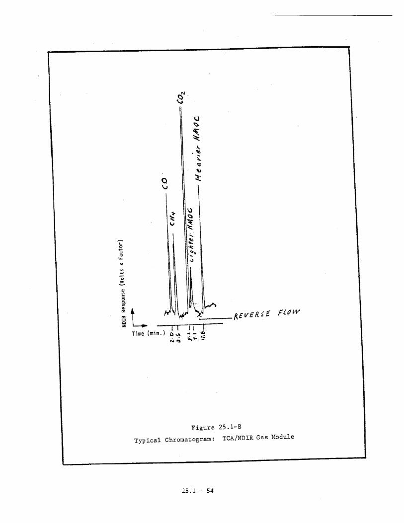
When the lighter compounds have come off
the column, set a boiling water (100oC)
bath on each column and immediately set
the backflush valve to the backflush
setting. Under these conditions the
heavier compounds will elute off the
silicone oil column. A copy of a typical
chromatogram is shown in Figure 25.1-8.
If any of the individual compounds of the
sample are greater than 1 percent
equivalent CO2, inject the sample again
using the small loop.

25.1-38
If any of the individual compounds of the
sample injected on the large loop show an
area count of 5 percent equivalent CO2,
dilute the sample to less than 1 percent
equivalent CO2 on the small loop. Run
each sample or its dilution in duplicate.
Follow the sample injection with the
appropriate standards as described in
Section 3.9.
3.6.2 Recovered Condensate (CO2)
The CO2 that has been collected in the
intermediate tanks from condensate
recovery must be quantified. Bypass the
columns, since speciation will not be
necessary. Using the appropriate sample
loops and dilutions as specified above,
make replicate injections of each
intermediate tank, followed by the
appropriate standard as described in
Section 3.9.

25.1-39
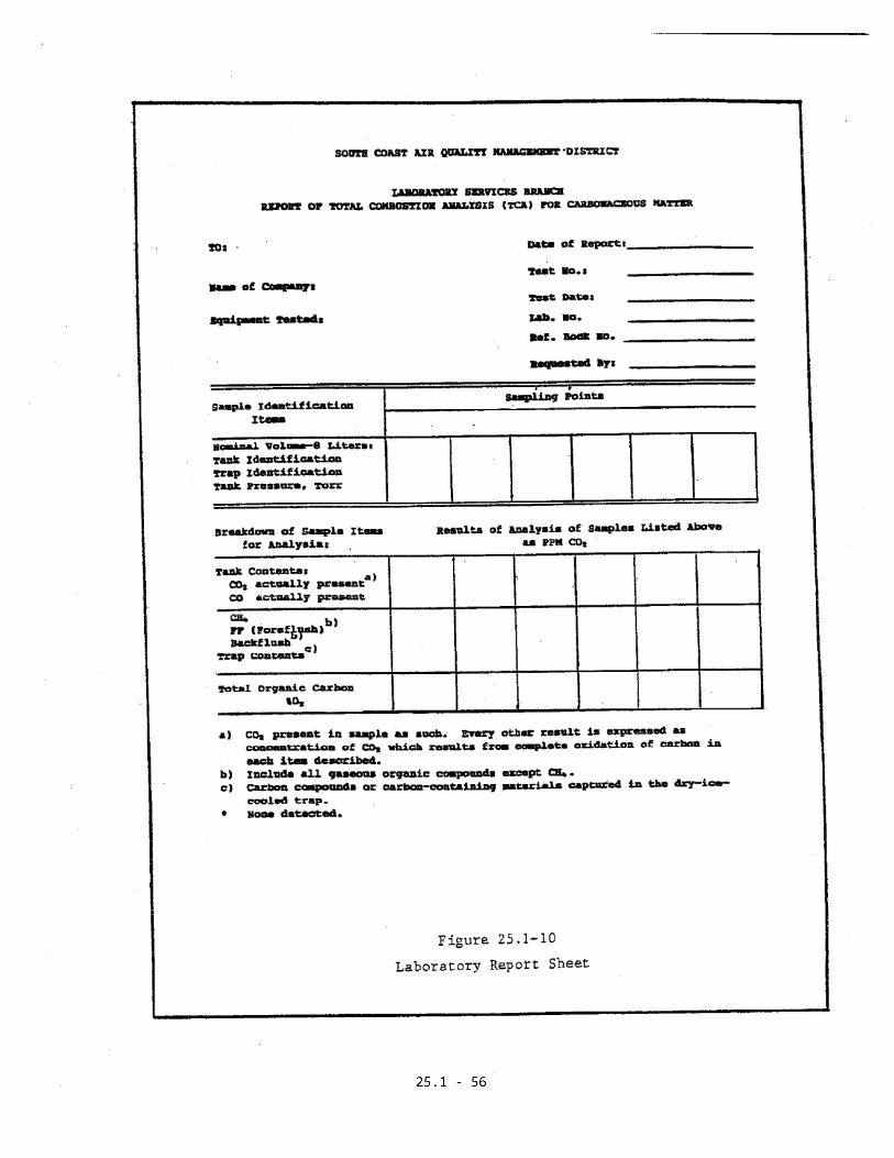
3.7 Calculations
3.7.1 Sample Tank
Concentrations of gaseous effluent
components present in the gaseous phase
are reported as concentrations of carbon
in parts per million by volume (ppm v/v):
Cst x Asa X PfCsa = -------------- x D
Ast x Pi
where:
Csa = CO, CH4, CO2, or backflush
concentration corresponding to
peak being measured, ppm v/v
Cst = Concentration of CO, CH4, or CO2
in the standard, ppm v/v
Asa = Area of charted response curve
for the CO, CH4, CO2 or backflush
sample in units identical to Ast

25.1-40
Ast = Area of charted response curve
for the standard in units
identical to Asa
Pf = Final pressure to which the
sample in the tank was
pressurized, Torr
Pi = Initial pressure of the sample in
the tank, as received after
sample collection, Torr
D = Dilution factor
Peak height can be used instead of areas
when the compound used in the calibrating
mixture is the same as the compound being
measured (i.e. CO, CH4, CO2). Since
backflushes are almost always mixtures of
several compounds, area must be used for
calculations.
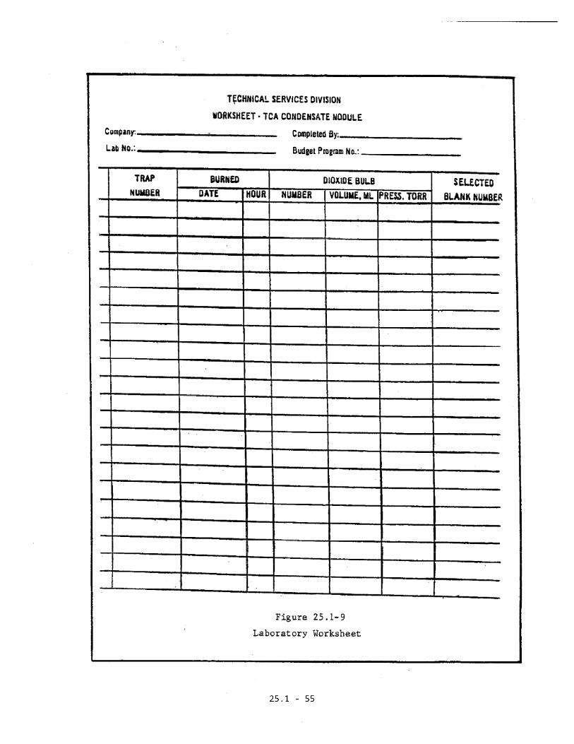
3.7.2 Condensate
The concentration of effluent components
present in the condensate trap are
reported as ppm v/v carbon:

25.1-41
Cst x Asa x Pf x VfCsa = ------------------- x D
Ast x Pi Vi
where the variables in addition to those
described in Section 2.7.1 are:
Vi = Volume of the bulb, tank, or bag
sample to which the trap was
originally attached, ml
Vf = Volume of the tank in which the
oxidized contents of the trap
were collected, ml
A convenient laboratory worksheet
is shown in Figure 25.1-9.
3.8 Calibrations
3.8.1 Tank Volume
Calibrate the tank or bulb volume by
weighing it empty and full of water.
Measure the temperature of the water by
using a mercury-in-glass thermometer

25.1-42
accurate to 0.1oC. Calculate the volume
according to the formula:
W1 - W2V = -------
Dt
where:
V = Volume of the tank or bulb, ml
W1-W2 = Weight of water, g
Dt = Density of water in g/ml at
temperature t
Report the volume to the nearest 10 ml.
Under ordinary circumstances a density of
0.9971 is representive for water 25oC.
The uncalibrated volume of the connections
on the tank side of the valve is estimated
to be less than 10 ml and considered as
negligible.
3.8.2 Gas Concentrations
25.1-43
Check the instrument response by injecting
a check standard before performing any
analyses. If the response is acceptable,
proceed with sample tank and condensate
analysis. Immediately calibrate each
sample component against CO2 standards
that are within 5 percent of the sample
peak areas when working in the non-linear
range of the NDIR. (This must be
determined beforehand.) Make a standard
injection for every concentration. Follow
the last sample analysis with replicate
injections of the check standard. A drift
of more than 10 percent invalidates the
results and requires sample reanalysis.
3.9 Quality Control
3.9.1 Balances
Used to calibrate tank volumes.
Must be accurate and repeatable.
3.9.2 Gas Standards
Must be NBS traceable.

25.1-44
METHOD 25.1
DETERMINATION OF TOTAL GASEOUS NON-METHANE ORGANIC EMISSIONSAS CARBON
Section 4 of 5
4. Engineering Calculations
Calculate the mass emission rate using the form as
shown in Figure 25.1-11.
This portion of this page intentionally blank.
Administrator
25.1 - 45

Administrator
25.1 - 46
Administrator
Administrator
Administrator
Administrator
Administrator
25.1 - 47

Administrator
25.1 - 48

Administrator
25.1 - 49
Administrator
25.1 - 50

Administrator
25.1 - 51

Administrator
25.1 - 52
Administrator
25.1 - 53
Administrator
25.1 - 54
Administrator
25.1 - 55
Administrator
25.1 - 56

Administrator
25.1 - 57

25.1-58
METHOD 25.1
DETERMINATION OF CARBON MONOXIDE, METHANE, AND TOTAL NON-METHANE ORGANIC COMPOUNDS AT LOW CONCENTRATIONS BY TOTAL
COMBUSTION ANALYSIS (TCA/FID)
Section 5 of 5
5. Alternative Laboratory Procedures
5.1 Apparatus
5.1.1 Sample Collection Train Preparation
For sampling apparatus refer to Section
3.1.1.
5.1.2 Sample Recovery
a. Gas Pressurization System
b. Manometer
Capable of measuring pressure to the
nearest 1 mm Hg in the 1 to 900 mm
range. Manometer must be NIST traceable.

25.1-59
5.1.3 Sample Analysis
The NMO analyzer is a GC with back flush
capability for NMO analysis and is
equipped with an oxidation catalyst,
reduction catalyst, and FID. TGNMO
sampling equipment can be constructed from
commercially available components
fabricated in a machine shop. NMO
analyzers are available commercially or
can be constructed from available
components by a qualified instrument
laboratory.
The NMO analyzer is a semi-continuous
GC/FID analyzer capable of: (1)
separating CO, CO2, and CH4 from NMO
compounds, (2) oxidizing the NMO to CO2,
and CO to CO2, and (3) reducing the CO2 to
CH4 and quantifying as CH4. See Figure
25.1-12 for a flow chart of the
instrument. The analyst must demonstrate
prior to initial use that the analyzer is
capable of proper separation, oxidation,
reduction, and measurement. The analyzer
consists of the following major
components:

25.1-60
a. Oxidation Catalyst
A catalyst system capable of oxidizing
CH4 to CO2 with at least 95 percent
efficiency is acceptable.
b. Reduction Catalyst
A catalyst system capable of reducing
CO2 to CH4 with at least 95 percent
efficiency is acceptable.
c. Separation Column(s)
Gas chromatographic column(s) capable
of separating CO, CO2, and CH4 from
NMO compounds. (See Section 5.2 for
column types).
d. Sample Injection System
A GC sample injection valve fitted
with a sample loop properly sized to
interface with the NMO analyzer. (A2
ml loop is recommended.)

25.1-61
e. FID with a linear response (+ 5
percent) over the operating range of
0.5 to 500 ppm C3H8.
f. Data Recording System
Digital integration system compatible
with the FID for permanently recording
the analytical results.
g. Syringe
Gas tight syringe, 30 ml.
h. Dewars
Size sufficient to surround the
chromatographic column.
5.2 Reagents
5.2.1 Sample Collection Train Equipment
Preparation
See Section 3.2.1.
5.2.2 Sample Analysis

25.1-62
a. Oxidation Catalyst
Hopcalite (MSA Part No. 41566) is
satisfactory. Pack 6 in. of granular
Hopcalite in the center of a 12 in. x
1/4 in. Inconel tube. Plug both ends
with quartz wool.
b. Reduction Catalyst
Finely divided nickel on 60 to 80 mesh
firebrick substrata, is satisfactory.
Prepare by dissolving nickel nitrate
in deionized water. Stir ten times
(by weight) as much firebrick 40 to 60
mesh into solution. Heat to dryness
in an oven at 200oF. Pack the center
of a 12 in. x 1/4 in. Inconel tube
with 6 in. of this catalyst. Plug
both ends with quartz wool.
c. Carrier Gas
Helium, chromatographic grade.
d. Hydrogen, Reagent Grade

25.1-63
For reduction of CO2 and FID fuel.
e. Air, USP Breathing Grade
For FID combustion.
f. Column Packing
1-1/2 ft. x 1/8 in. of 10 percent SE
30 on Chromosorb W 80 to 100 mesh, and
4-1/2 ft. x 1/8 in. of Porapak Q 80 to
100 mesh. Column may be made
symmetric by adding another 1-1/2 ft.
of S E30 on Chromosorb W at the other
end of the column.
g. Calibration Gas
50 ppm CO, 50 ppm CH4, 25 ppm ethane,
10 ppm isopentane in nitrogen, and
other separate standards as required.
h. Water Baths

25.1-64
Water baths at 0oC (ice water), 20oC
(nominal-ambient) and 100oC (boiling
water) are required.
5.3 Pretest Preparation
See Section 3.3.
5.4 Preparation of Sample Collection Train
See Section 3.4.
5.5 Sample Recovery
See Section 3.5.2 (Tanks).
5.6 Sample Analysis
Set instrument parameters as follows:
Detector : 250oC
Oxidation catalyst : 650oC
Reduction catalyst : 350oC
10 port valve oven : 150oC
Heated transfer lines : 105oC
Gas flow rates
Carrier : Helium, 25 ml/min

25.1-65
Air : 180 ml/min
Hydrogen : 24 ml/min
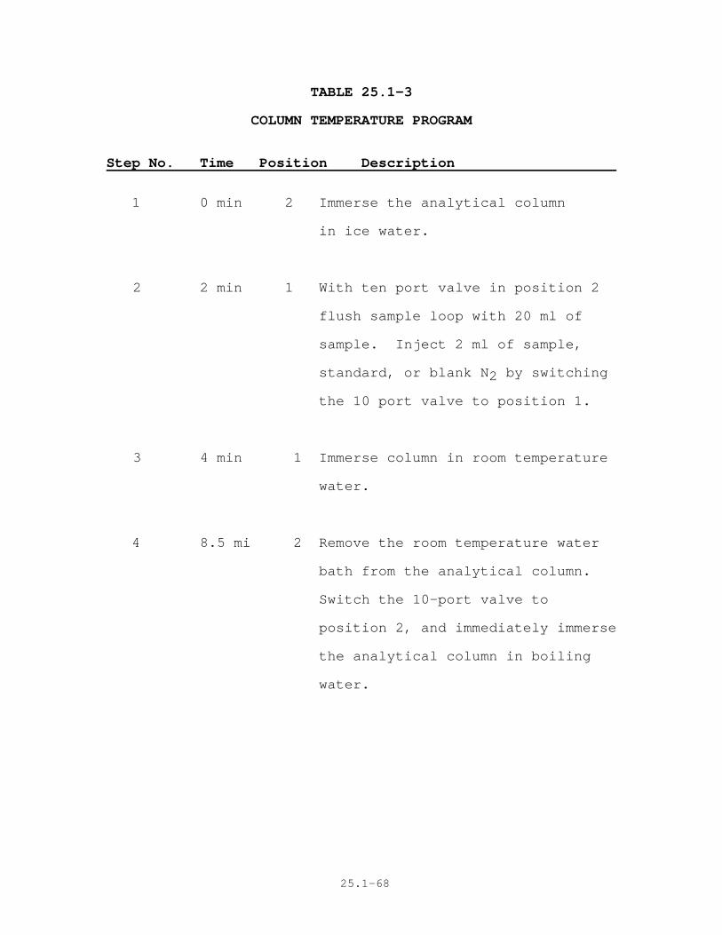
Reproduce exactly the timing of valve switching
and column temperature changes for each blank,
sample, and standard run in a series. Analyze
low concentration samples before high
concentration samples. Prior to sample analysis,
determine system background for non-methane
hydrocarbons by injecting pure (99.999 percent)
nitrogen into the system and following the timing
sequence as for an actual sample. Table 25.1-3
shows a listing of the timing sequence.
Figure 25.1-13 shows where the step number
appears on a plot of response vs. time. Step one
establishes the 0oC column temperature required
for separation of CO, CO2, CH4, and non-methane
hydrocarbons. Step two injects the sample and
switches carrier flow in the forward direction.
(See Figure 25.1-14.) Step three allows CO2 to
be eluted quickly from the columns. Switching
the sample injection valve and immersing the
column into boiling water for Step 4 reverses
carrier flow direction and elutes NMO as a back-
flush peak. Detector output for the back-flush
peak is sent to a where a response vs. time curve
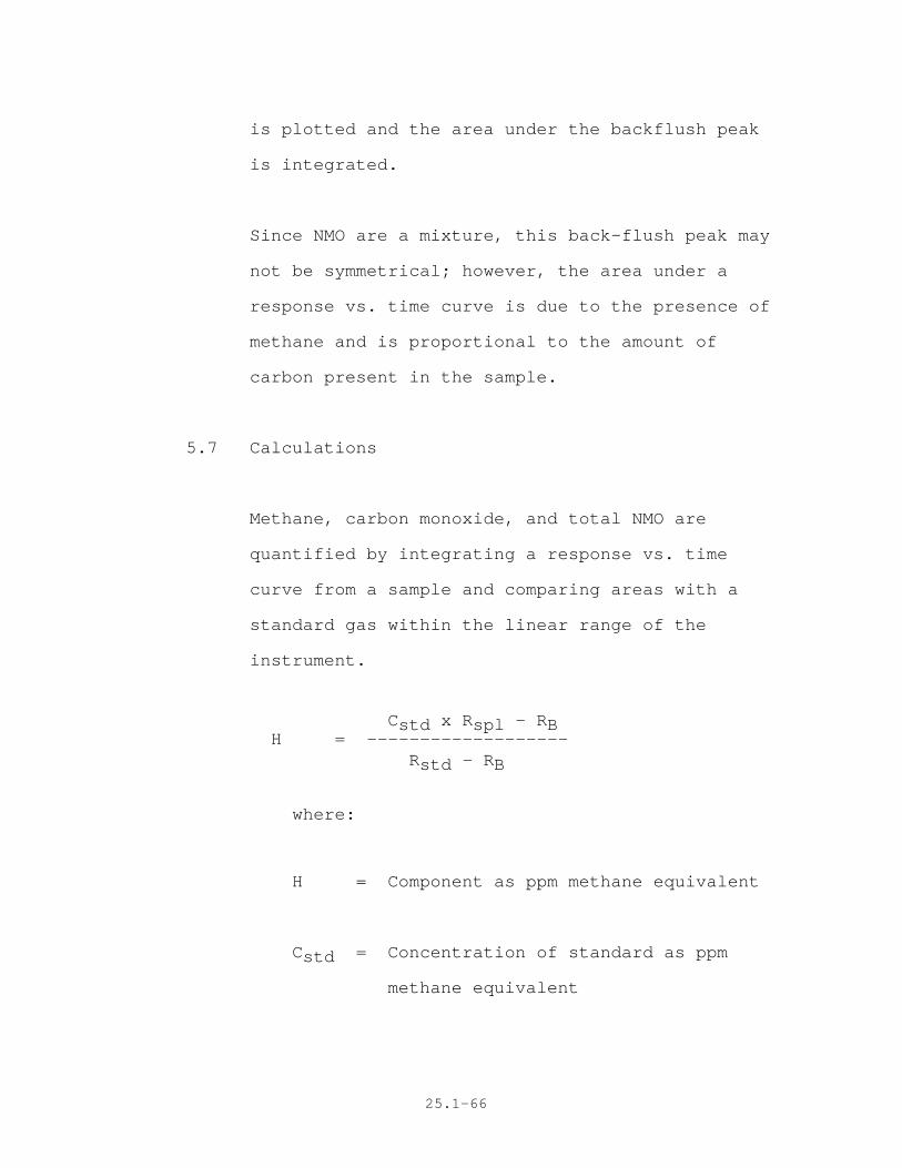
25.1-66
is plotted and the area under the backflush peak
is integrated.
Since NMO are a mixture, this back-flush peak may
not be symmetrical; however, the area under a
response vs. time curve is due to the presence of
methane and is proportional to the amount of
carbon present in the sample.
5.7 Calculations
Methane, carbon monoxide, and total NMO are
quantified by integrating a response vs. time
curve from a sample and comparing areas with a
standard gas within the linear range of the
instrument.
Cstd x Rspl - RB H = -------------------
Rstd - RB
where:
H = Component as ppm methane equivalent
Cstd = Concentration of standard as ppm
methane equivalent

25.1-67
Rspl = Response from sample (area)
Rstd = Response from standard (area)
RB = Response from blank (area)
Administrator
25.1-68
TABLE 25.1-3
COLUMN TEMPERATURE PROGRAM
Step No. Time Position Description
1 0 min 2 Immerse the analytical column
in ice water.
2 2 min 1 With ten port valve in position 2
flush sample loop with 20 ml of
sample. Inject 2 ml of sample,
standard, or blank N2 by switching
the 10 port valve to position 1.
3 4 min 1 Immerse column in room temperature
water.
4 8.5 mi 2 Remove the room temperature water
bath from the analytical column.
Switch the 10-port valve to
position 2, and immediately immerse
the analytical column in boiling
water.

25.1-69
5 12 min 2 Remove the boiling water bath
and immerse the analytical
column in ice water, beginning
the sequence again at Step 1
and time zero.

Administrator
25.1 - 70

Administrator
25.1 - 71

Administrator
25.1 - 72