Methane Hydrates: CO2 storage and natural gas production · IFM-GEOMAR ; L3 Communications ELAC...
33
CO 2 CH 4 Methane Hydrates: CO 2 storage and natural gas production
Transcript of Methane Hydrates: CO2 storage and natural gas production · IFM-GEOMAR ; L3 Communications ELAC...

CO2 CH4
Methane Hydrates: CO2 storage and natural gas production
Source: IPCC (2007): Climate Change - Mitigation
Hydrate technologies may contribute to the reduction of CO2 emissions from fossil fuel power plants

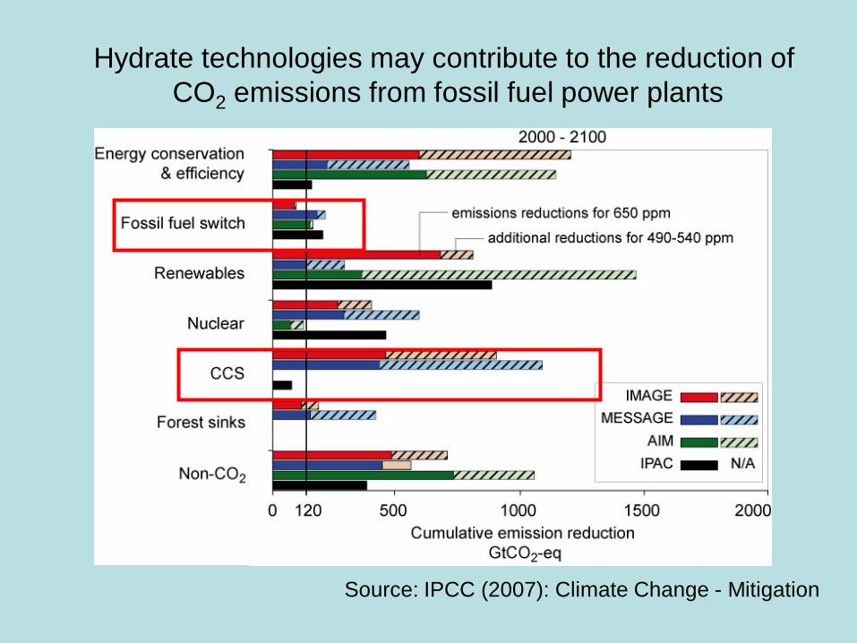
Global Methane Hydrate Distribution
0 200 500 kg C/m2
Source: Modeling study by Burwicz, Rüpke & Wallmann (GCA, 2011)
Hydrates formed by microbial methane production within the GHSZ: 990 Gt C
Global Methane Hydrate Distribution
Pinero, Wallmann et al. (unpub.)
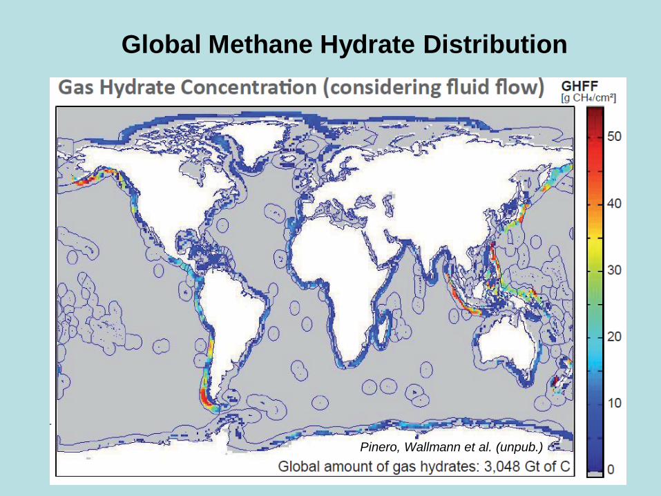
Global Methane Hydrate Inventory in the Seabed
Kven. (1999)
Mil. (2004)
Buff. (2004)
Klau. (2005)
Best estimate 3000 2000
Gt C
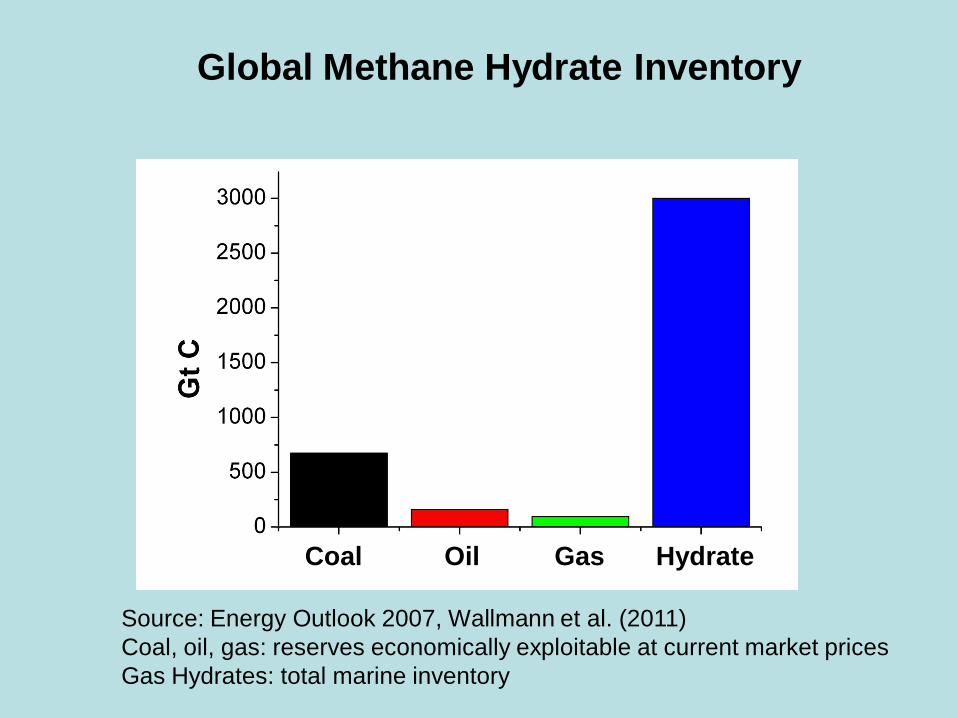
Global Methane Hydrate Inventory
Coal Oil Gas Hydrate
Source: Energy Outlook 2007, Wallmann et al. (2011) Coal, oil, gas: reserves economically exploitable at current market prices Gas Hydrates: total marine inventory

Hydrate Exploitation
Methane gas may be produced from hydrate deposits via:
• Pressure reduction
• Temperature increase
• Addition of CO2

Hydrate Exploitation
Energy balance for gas production via heat addition at Blake Ridge (Makogon et al. 2007) 2000 m water depth, two ~3 m thick hydrate layers ~40 % of the potential energy can be used for energy production while ~60 % of the potential energy is lost during development, gas production, and transport Japanese Hydrate Exploitation Program Hydrate exploitation via pressure reduction has a much better energy balance and may be economically feasible. However, gas production rates are limited by the temperature drop in the reservoir induced by the endothermic gas hydrate dissociation process.

CH4-recovery from hydrates exposed to CO2
after 200 h in sandstone CO2(l) Kvamme et al. (2007)
CO2(l) Hiromata et al. (1996) after 400 h
CO2(g)/N2(g) Park et al. (2006)
CO2(g) Lee et al. (2003) after 5 h
after 15 h
Spontaneous exothermic reaction !

International Hydrate Research (2012 – 2014)
Field production tests (USA, Japan)
On-shore Alaska (Prudhoe Bay, below permafrost) • 2012 – 2014 (DOE, BP): Pressure reduction (long-term) • 2012 (DOE, ConocoPhillips): CO2 injection (short-term) Off-shore Japan (~1000 m water depth)
• 2012 (MH 21): Pressure reduction (short-term) • 2014 (MH 21): Pressure reduction (long-term)

The SUGAR Project
• Funded by German Federal Ministries (BMWi, BMBF)
• First funding period: July 2008 – June 2011
• Total funding: ~13 Mio € (incl. support by industries)
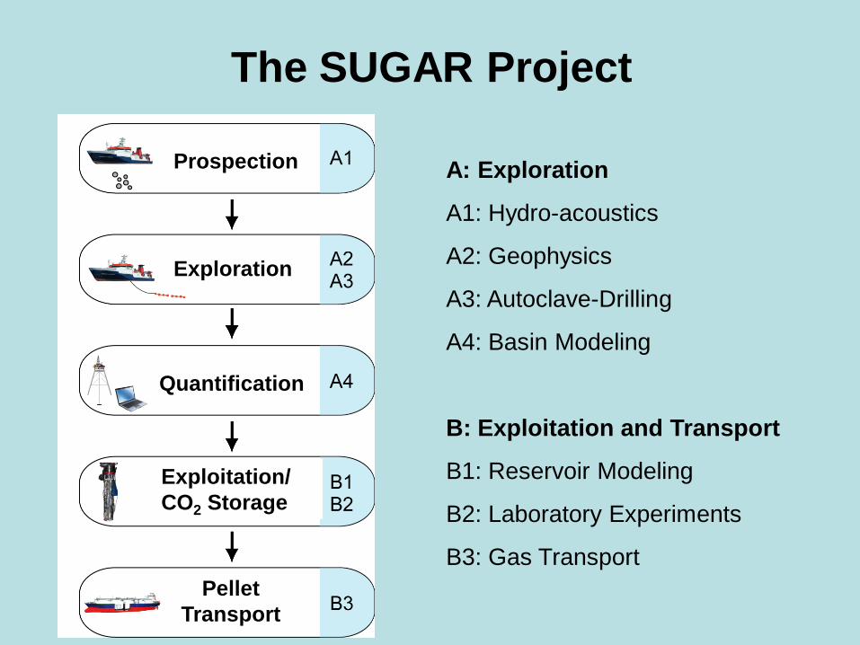
A: Exploration
A1: Hydro-acoustics
A2: Geophysics
A3: Autoclave-Drilling
A4: Basin Modeling
B: Exploitation and Transport
B1: Reservoir Modeling
B2: Laboratory Experiments
B3: Gas Transport
Prospection
Exploration
Quantification
Exploitation/ CO2 Storage
Pellet Transport
The SUGAR Project

Project Academia Industries A1 IFM-GEOMAR L3 Communications ELAC Nautik
GmbH
A2 IFM-GEOMAR, BGR Hannover K.U.M. Umwelt- und Meerestechnik GmbH, Magson GmbH, SEND Offshore GmbH
A3 University of Bremen, TU Clausthal
Bauer PRAKLA Bohrtechnik GmbH
A4 IFM-GEOMAR Schlumberger-IES
B1 Fraunhofer UMSICHT, GFZ Potsdam, IFM-GEOMAR
Wintershall, Aker-Wirth GmbH
B2 FH Kiel, GFZ Potsdam, Fraunhofer UMSICHT, IFM-GEOMAR, Uni Göttingen
BASF, CONTROS GmbH, R&D Center at FH Kiel, 24sieben Stadtwerke Kiel AG, RWE Dea, Wintershall, E.ON Ruhrgas AG
B3 IOW, FH Kiel Linde AG, Meyer Yards, Germanischer Lloyd, BASF
SUGAR Partners
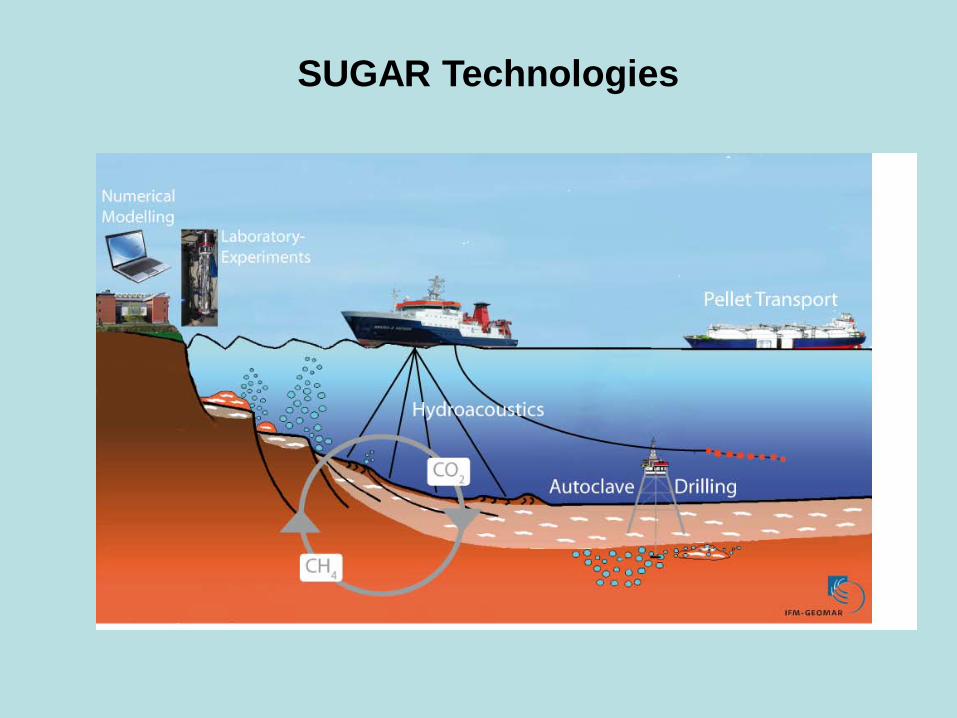
SUGAR Technologies
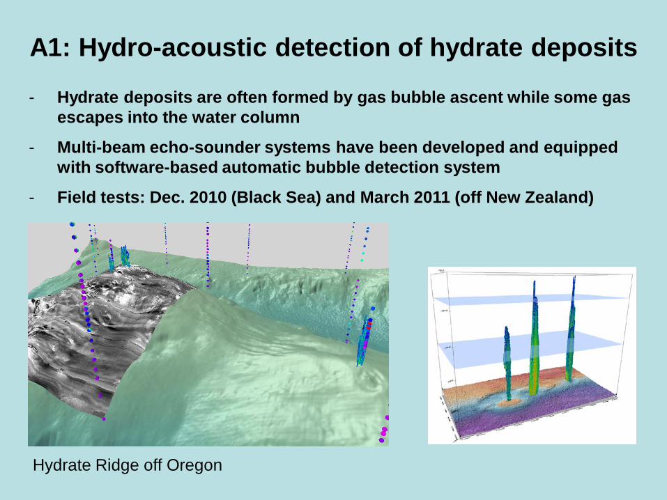
- Hydrate deposits are often formed by gas bubble ascent while some gas escapes into the water column
- Multi-beam echo-sounder systems have been developed and equipped with software-based automatic bubble detection system
- Field tests: Dec. 2010 (Black Sea) and March 2011 (off New Zealand)
A1: Hydro-acoustic detection of hydrate deposits
Hydrate Ridge off Oregon
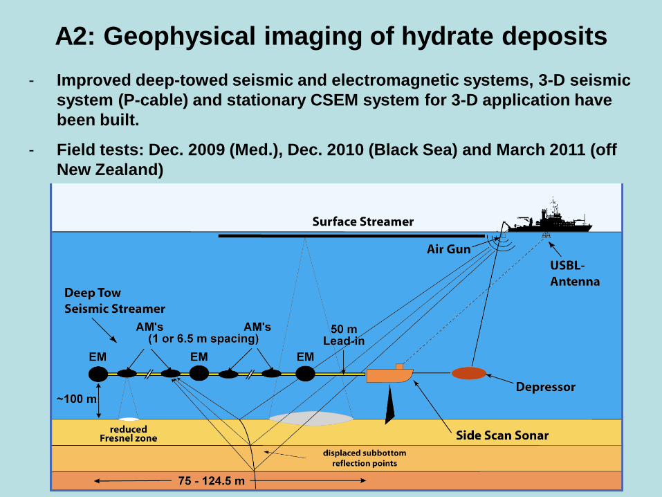
A2: Geophysical imaging of hydrate deposits - Improved deep-towed seismic and electromagnetic systems, 3-D seismic
system (P-cable) and stationary CSEM system for 3-D application have been built.
- Field tests: Dec. 2009 (Med.), Dec. 2010 (Black Sea) and March 2011 (off New Zealand)
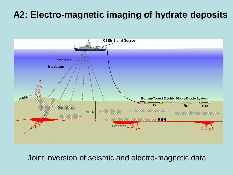
A2: Electro-magnetic imaging of hydrate deposits
Joint inversion of seismic and electro-magnetic data
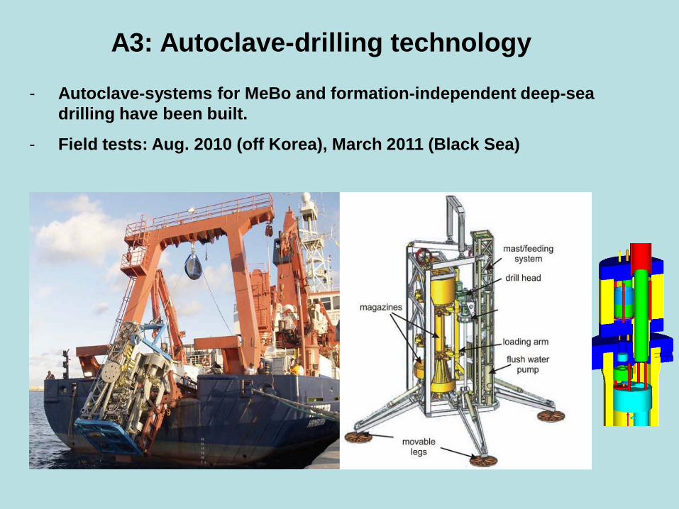
A3: Autoclave-drilling technology
- Autoclave-systems for MeBo and formation-independent deep-sea drilling have been built.
- Field tests: Aug. 2010 (off Korea), March 2011 (Black Sea)
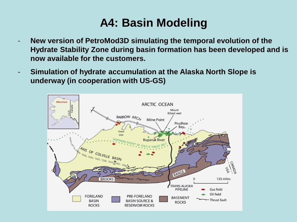
A4: Basin Modeling - New version of PetroMod3D simulating the temporal evolution of the
Hydrate Stability Zone during basin formation has been developed and is now available for the customers.
- Simulation of hydrate accumulation at the Alaska North Slope is underway (in cooperation with US-GS)

A4: Basin Modeling
Initial results for Alaska North Slope with new PetroMod release
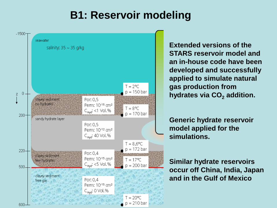
B1: Reservoir modeling
- Extended versions of the STARS reservoir model and an in-house code have been developed and successfully applied to simulate natural gas production from hydrates via CO2 addition.
- Generic hydrate reservoir model applied for the simulations.
- Similar hydrate reservoirs occur off China, India, Japan and in the Gulf of Mexico
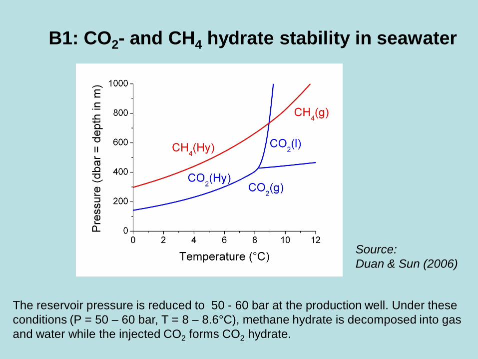
B1: CO2- and CH4 hydrate stability in seawater
Source: Duan & Sun (2006)
The reservoir pressure is reduced to 50 - 60 bar at the production well. Under these conditions (P = 50 – 60 bar, T = 8 – 8.6°C), methane hydrate is decomposed into gas and water while the injected CO2 forms CO2 hydrate.
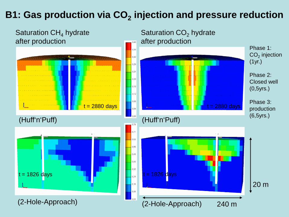
(Huff‘n‘Puff) (Huff‘n‘Puff)
(2-Hole-Approach) (2-Hole-Approach)
Saturation CH4 hydrate after production
Saturation CO2 hydrate after production
t = 2880 days t = 2880 days
t = 1826 days t = 1826 days
Phase 1: CO2 injection (1yr.) Phase 2: Closed well (0,5yrs.) Phase 3: production (6,5yrs.)
B1: Gas production via CO2 injection and pressure reduction
240 m
20 m

B1: Gas production via CO2 injection and pressure reduction
Time (d)
Gas
pro
duct
ion
rate
(x10
³ Nm
³/d)
Gas
pro
duct
ion
(cum
. x10
³ Nm
³)
2-Hole
Huff‘n Puff
Composition of produced gas: ~99% CH4, ~1% CO2
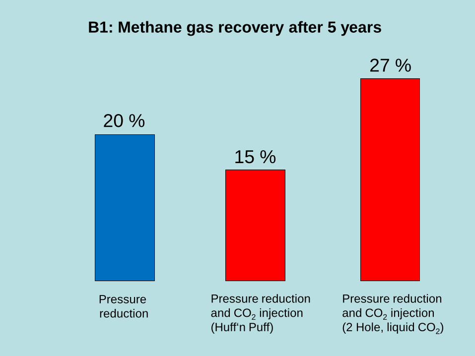
B1: Methane gas recovery after 5 years
Pressure reduction
Pressure reduction and CO2 injection (2 Hole, liquid CO2)
Pressure reduction and CO2 injection (Huff‘n Puff)
20 %
15 %
27 %

B2: Laboratory experiments
- High-pressure labs were set-up at GFZ-Potsdam, IFM-GEOMAR, Univ. Göttingen, and Fraunhofer UMSICHT.
- In-situ composition of methane has been tested successfully at GFZ-Potsdam with 10% Pd-ZrO as most robust and efficient catalyst.
- Polymers accelerate methane hydrate decomposition and CH4-CO2 gas exchange in hydrates significantly (BASF, Univ. Göttingen)
- Methane hydrates are exposed to supercritical CO2 to accelerate methane gas production from hydrates (IFM-GEOMAR). First results indicate rapid and efficient methane release from hydrates exposed to super-critical CO2.
- Mechanisms of gas exchange in hydrates have been studied using Raman microscopy and XRD (IFM-GEOMAR, GFZ Potsdam, Univ. Göttingen)

B2: Mechanisms of gas exchange
With liquid and gaseous CO2, the exchange reaction proceeds in 2 steps: a faster surface reaction at beginning followed by a slower permeation-controlled gas exchange, max. 50 % gas recovery due to formation of mixed CO2-CH4 hydrates (W. Kuhs, Univ. Göttingen)
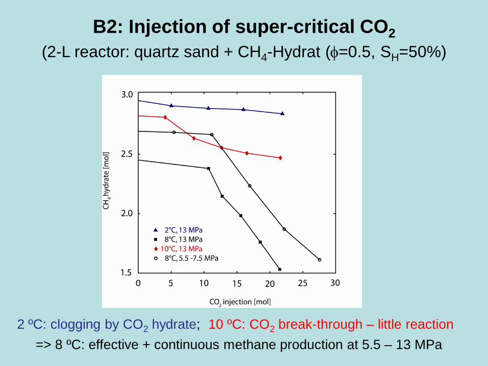
B2: Injection of super-critical CO2 (2-L reactor: quartz sand + CH4-Hydrat (φ=0.5, SH=50%)
2 ºC: clogging by CO2 hydrate; 10 ºC: CO2 break-through – little reaction => 8 ºC: effective + continuous methane production at 5.5 – 13 MPa

CH4-recovery from hydrates in sand matrix exposed to CO2
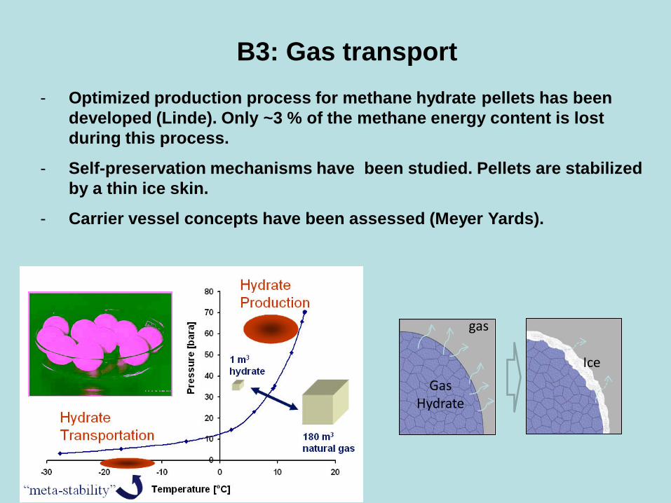
B3: Gas transport - Optimized production process for methane hydrate pellets has been
developed (Linde). Only ~3 % of the methane energy content is lost during this process.
- Self-preservation mechanisms have been studied. Pellets are stabilized by a thin ice skin.
- Carrier vessel concepts have been assessed (Meyer Yards).
gas
Gas Hydrate
Ice
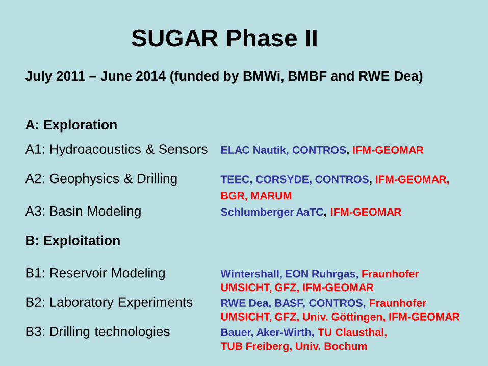
July 2011 – June 2014 (funded by BMWi, BMBF and RWE Dea)
A: Exploration
A1: Hydroacoustics & Sensors ELAC Nautik, CONTROS, IFM-GEOMAR A2: Geophysics & Drilling TEEC, CORSYDE, CONTROS, IFM-GEOMAR, BGR, MARUM A3: Basin Modeling Schlumberger AaTC, IFM-GEOMAR B: Exploitation B1: Reservoir Modeling Wintershall, EON Ruhrgas, Fraunhofer UMSICHT, GFZ, IFM-GEOMAR B2: Laboratory Experiments RWE Dea, BASF, CONTROS, Fraunhofer UMSICHT, GFZ, Univ. Göttingen, IFM-GEOMAR B3: Drilling technologies Bauer, Aker-Wirth, TU Clausthal, TUB Freiberg, Univ. Bochum
SUGAR Phase II
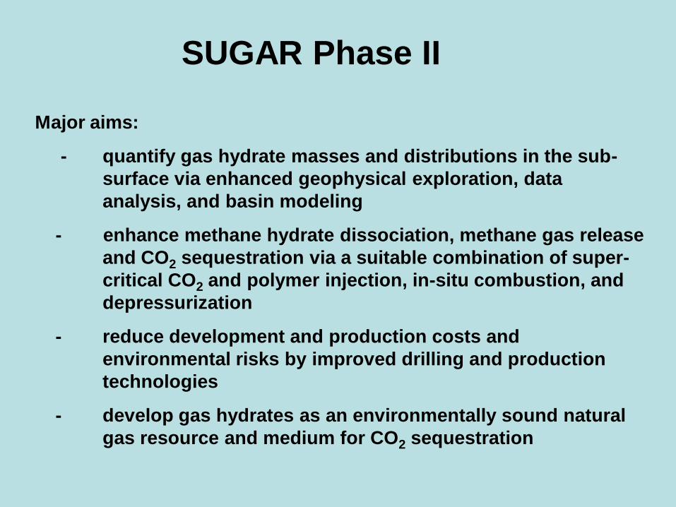
Major aims:
- quantify gas hydrate masses and distributions in the sub- surface via enhanced geophysical exploration, data analysis, and basin modeling
- enhance methane hydrate dissociation, methane gas release and CO2 sequestration via a suitable combination of super- critical CO2 and polymer injection, in-situ combustion, and depressurization
- reduce development and production costs and environmental risks by improved drilling and production technologies
- develop gas hydrates as an environmentally sound natural gas resource and medium for CO2 sequestration
SUGAR Phase II
Bulgaria, Georgia, Romania, Russia, Turkey, Ukraine (Black Sea): Joint exploration cruises, joint workshop (March 27th – 28th, 2012) New Zealand: Joint exploration cruises (2011) US: Numerical basin simulation North Alaska Slope (2011 - 2014) France (Total): Joint exploration cruise off West Africa (2012) Taiwan: Joint exploration cruises (2013) India: Joint workshops, CLIENT proposal, pending Japan, China, South Korea: Joint workshops Brazil (Petrobras): CONEGAS project, joint exploration cruise (pending) US: Numerical basin simulation Alaska North Slope (2011 - 2014) UNEP: Report on gas hydrates (2012) EU: Coordinated program on environmental risks of sub-seabed CO2 storage (ECO2: 2011 - 2015) International off-shore field production test with CO2 injection (~2015)
International cooperations


![Klaus Wallmann (GEOMAR) and colleagues from NIVA, GEOMAR, …oceanrep.geomar.de/29074/1/D11.3[1].pdf · monitoring of sub-seabed storage sites. ECO 2 recommends that overburden, seabed,](https://static.fdocuments.us/doc/165x107/5f19b22f4fe20a6a19364b5c/klaus-wallmann-geomar-and-colleagues-from-niva-geomar-1pdf-monitoring-of.jpg)