Meter Asset Manager Code of Practice - Office of Gas and · PDF file3 Requirements of Meter...
100
1 CODE OF PRACTICE FOR GAS METER ASSET MANAGERS Version 1.0 September 2005
Transcript of Meter Asset Manager Code of Practice - Office of Gas and · PDF file3 Requirements of Meter...

1
CODE OF PRACTICE FOR
GAS METER ASSET MANAGERS
Version 1.0
September 2005
2
Contents
1 Scope ............................................................................................................................................. 4
2 Introduction ....................................................................................................................................... 5
3 Requirements of Meter Asset Manager (MAM) ................................................................................ 7
4 Planning ............................................................................................................................................. 10
5 Design and the Selection of Fittings .................................................................................................. 15
6 Approval, Appraisal, and Authorisation by Third Parties.................................................................. 18
7 Installation ......................................................................................................................................... 21
8 Modifications ..................................................................................................................................... 26
9 Commissioning .................................................................................................................................. 31
10 Provision of Information.................................................................................................................... 38
11 Operation ........................................................................................................................................... 40
12 Maintenance....................................................................................................................................... 42
13 Inspections Arising Under Statutory Requirements or Licence Conditions ...................................... 46
14. Duty of Care Beyond Asset ............................................................................................................... 49
15 Duty of Co-operation ......................................................................................................................... 50
16 Meter Readings Required to be Performed by MAMs ...................................................................... 51
17 Installation Performance and Functionality Monitoring .................................................................... 52
18 Cessation of Gas Supply .................................................................................................................... 55
19 Removal and Return of Meters and Installation Kit .......................................................................... 57
20 Asset Records .................................................................................................................................... 60
21 Asset Transfer from MAM to MAM (Guidance only) ...................................................................... 61
22 Permanent Disposal ........................................................................................................................... 62
TABLES :
Table for Sub-Section 4.2: Planning – Specific 12
Table for Sub-Section 5.2: Design and the Selection of Fittings – Specific 16
Table for Sub-Section 6.2: Approval, Appraisal, and Authorisation by Third Parties - Specific 18
Table for Sub-Section 6.3: Approval, Appraisal, and Authorisation by Third Parties, Gas Safety
(Management Regulations) (GS(M)R) Safety Case 20
Table for Sub-Section 7.2: Installation - Specific 23
Table for Sub-Section 7.3: Installation - Pre-installation procedures 24
Table for Sub-Section 7.4: Installation - Installation 25
Table for Sub-Section 8.3: Modifications – Meter Housing 26
Table for Sub-Section 8.4: Modifications – Formal Notification 26
Table for Sub-Section 8.6: Modifications – Credit or Pre-payment Meter Exchange 27
Table for Sub-Section 8.7: Modifications– Unsuitable Installations 28
Table for Sub-Section 8.8: Modifications - Repositioning 28
Table for Sub-Section 8.9: Modifications - Upgrading to Current Standards 29
Table for Sub-Section 8.10: Modifications - Ancillary Replacement (for example converters, AMR,
dataloggers etc.) 30
Table for Sub-Section 9.1: Commissioning - General 31
Table for Sub-Section 9.4: Physical Pre-commissioning Checks on the Installation 33
Table for Sub-Section 9.5: Commissioning - Commissioning Procedures 35
Table for Sub-Section 9.6: Commissioning – Test Equipment 36
Table for Sub-Section 12.2: Maintenance – Maintenance Procedures 43
Table for Sub-Section 12.3: Maintenance – Specific Maintenance Requirements 44
Table for Sub-Section 13.4: Inspections Arising Under Statutory Requirements or Licence Conditions -
Electricity at Work Regulations (EWR) 47
Table for Sub-Section 13.5: Gas Suppliers Safety Inspections 48
Table for Sub-Section 16.2: Meter Readings Required to be Performed by MAMs 51
Table for Sub-Section 17.4: Installation Performance and Functionality Monitoring - Non Specific 52
Table for Sub-Section 17.4: Installation Performance and Functionality Monitoring - Disputed Meter
Testing 53
Table for Sub-Section 17.5: Installation Performance and Functionality Monitoring - Procedure for
Sample Testing 54
Table for Sub-Section 18.2: Cessation of Gas Supply - Specific 55
Table for Sub-Section 19.1: Removal and Return of Meters and Installation Kit – General 57
Table for Sub-Section 19.2: Removal and Return of Meters and Installation Kit – Specific 58
Table for Sub-Section 20.3: Asset Records – Mandatory Records 60
3
ANNEXES
Annex 1: Comparison with OAMI Codes of Practice ......................................................................... 63
Annex 2: Example of a Code of Conduct ............................................................................................ 64
Annex 3: Legislative References and Technical PublicationsAnnex 3: Legislative References and Technical
Publications ......................................................................................................................................... 66
Annex 4: Glossary of Terms ................................................................................................................ 69
Annex 5: Connection and Disconnection Notification – Information Requirements .......................... 74
Annex 6: Competency ......................................................................................................................... 75
Annex 7: Meter By-Pass Provision and Use ........................................................................................ 89
Annex 8: Seals and Sealing Methods ................................................................................................... 92

4
1 Scope
1.1 This Code of Practice for Gas Meter Asset Managers (hereafter referred to as the MAMCoP)
applies to natural gas only.
1.2 The MAMCoP amplifies the duties of a Meter Asset Manager (MAM) where a MAM is as
defined in Annex 4.
1.3 The MAMCoP applies to Independent Gas Transporters undertaking meter asset management
services, as part of a bundled gas transportation business, or MAMs who work on behalf of a
gas supplier, GT or a gas consumer, to manage primary meter installations connected to the
Network as defined by the Gas Safety (Management) Regulations (GS(M)R) in Great Britain.
1.4 The MAMCoP utilises the definition of the meter installation which appears in IGE/G/1.
1.5 The MAMCoP expands on the requirements laid down in the Codes of Practice (CoPs) for
Ofgem Approved Meter Installers (OAMIs), COP/1a, COP/1b and COP/1c, by specifying the
requirements for all stages of the meter installation‟s life. For the purposes of OAMI
registration and compliance with Condition 34 of the Standard Conditions of Gas Suppliers
Licences, conformance with the applicable sections of the MAMCoP will be deemed to be
equivalent to conformance with the relevant Ofgas CoP. At a date (to be decided) the Ofgas
CoPs will be withdrawn. The date will be determined when all training and competency
modules, currently under review, are complete. In the meantime, for the purposes of initial
Ofgem MAM approval, meter installation competency requirements will continue in line with
current CoPs and, where relevant, specialist training. The correlation between requirements of
the MAMCoP and the Ofgas CoPs is laid out in the table of Annex 1.
1.6 The MAMCoP specifies the activities involved in the management of the life cycle of the
meter installation for which the MAM is responsible. Each activity is dealt with in its own
section. Clauses within each section deal with specific requirements.
1.7 This version replaces „Final Draft‟ dated 17 June 2004.
Note: Individual gas consumers, who undertake legal duties for their own gas meter installation(s) are not obliged to
register as a MAM. However, this document refers to the statutory responsibilities and provides guidance to all persons
responsible for any gas meter installation.

5
2 Introduction
2.1 The gas industry, through the Review of Gas Metering Arrangements (RGMA) project, has
designed and baselined standard industry-wide processes and data flows to support a
competitive gas metering market. (See RGMA Processes and Data with corresponding
Appendix and Market Domain document on the Metering (RGMA) page of the Ofgem web
site). The consequent liberalisation of the gas supply market and its ancillary services has
created the opportunity for the development of Meter Asset Management businesses.
2.2 These procedures assume that the gas supplier, gas transporter (GT) or consumer will contract
the MAM, or, in the case of Independent Gas Transporters, make internal arrangements to
undertake meter work or asset management activities. Work dataflows should conform to
RGMA processes.
This MAMCoP is designed to cover all technical requirements to be undertaken by a MAM.
The MAMCoP facilitates RGMA but does not cover all commercial and business information
flows required by either the RGMA baseline or contractual requirements. Any MAM seeking
Ofgem approval must be compliant with the RGMA baseline. The onus is placed on the
MAM to ensure compliance with requirements outside the technical framework.
2.3 The effective management of gas meter assets involves an awareness of, and conformance to,
a considerable number of disparate regulatory requirements and industry standards. This
MAMCoP provides new and existing MAMs with a route-map to conformance with those
requirements and industry standards. Its aim is to promote the safe and effective management
of gas supply meter installations throughout the asset‟s lifetime within the MAMCoP scope.
2.4 Where possible, this document is structured such that MAM activities are dealt with in the
order they occur in the life cycle of the meter. Each activity is dealt with in its own section.
Clauses within each section deal with specific requirements.
Where appropriate, a table is provided at the end of each section that shows the legislation,
technical standards and competencies applicable to each clause.
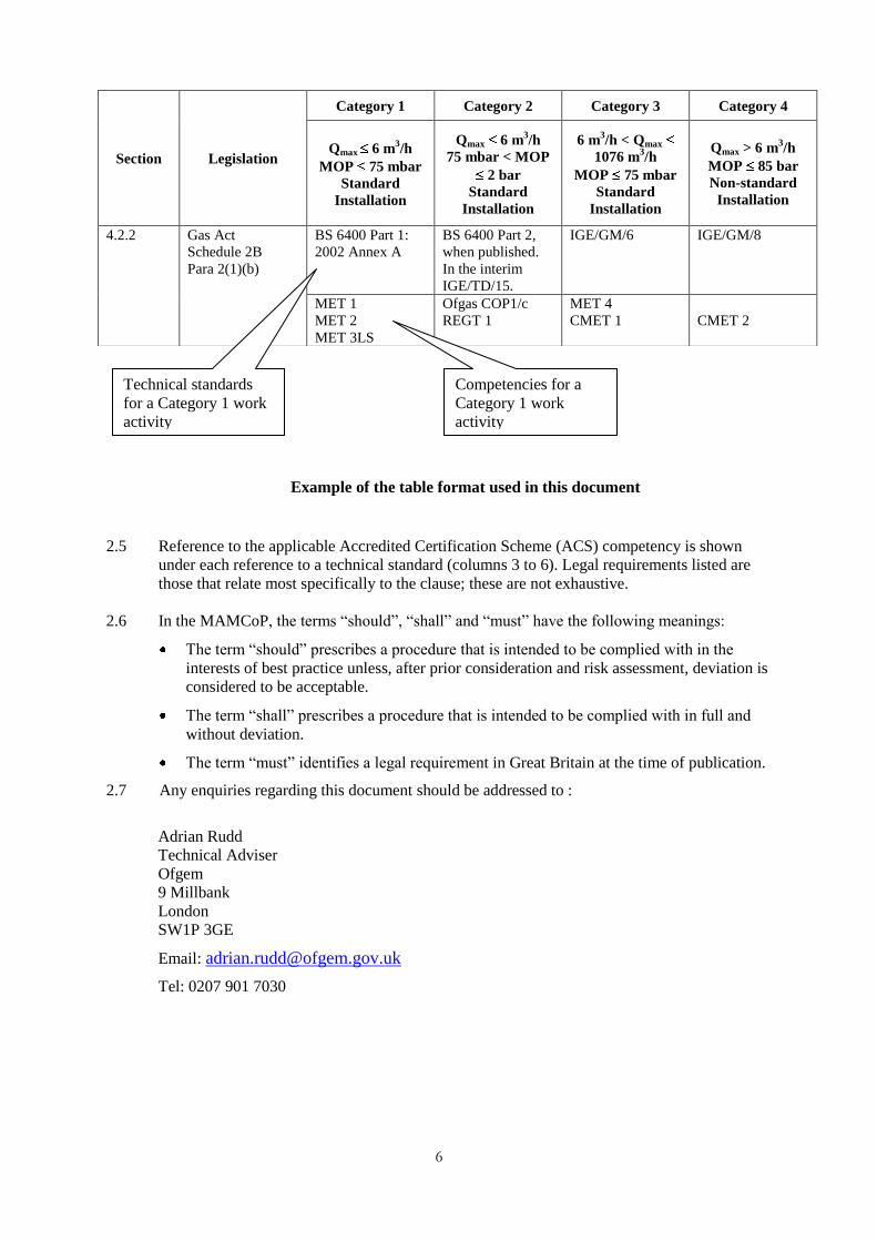
The tables use the following format:
Column 1: clause reference
Column 2: underlying legal requirement
Column 3 to 6: the technical standards to be followed for each of the four categories
of installation. Underneath the box containing the technical standard,
any appropriate competencies are listed.
Note: Where there is no appropriate legal requirement or a standard does not
exist then the corresponding box will be blank.
An example is shown on the next page.
6
Example of the table format used in this document
2.5 Reference to the applicable Accredited Certification Scheme (ACS) competency is shown
under each reference to a technical standard (columns 3 to 6). Legal requirements listed are
those that relate most specifically to the clause; these are not exhaustive.
2.6 In the MAMCoP, the terms “should”, “shall” and “must” have the following meanings:
The term “should” prescribes a procedure that is intended to be complied with in the
interests of best practice unless, after prior consideration and risk assessment, deviation is
considered to be acceptable.
The term “shall” prescribes a procedure that is intended to be complied with in full and
without deviation.
The term “must” identifies a legal requirement in Great Britain at the time of publication.
2.7 Any enquiries regarding this document should be addressed to :
Adrian Rudd
Technical Adviser
Ofgem
9 Millbank
London
SW1P 3GE
Email: [email protected]
Tel: 0207 901 7030
Section Legislation
Category 1 Category 2 Category 3 Category 4
Qmax 6 m3/h
MOP 75 mbar
Standard
Installation
Qmax 6 m3/h
75 mbar < MOP
2 bar
Standard
Installation
6 m3/h < Qmax
1076 m3/h
MOP 75 mbar
Standard
Installation
Qmax > 6 m3/h
MOP 85 bar
Non-standard
Installation
4.2.2 Gas Act
Schedule 2B
Para 2(1)(b)
BS 6400 Part 1:
2002 Annex A
BS 6400 Part 2,
when published.
In the interim
IGE/TD/15.
IGE/GM/6 IGE/GM/8
MET 1
MET 2
MET 3LS
Ofgas COP1/c
REGT 1
MET 4
CMET 1
CMET 2
Competencies for a
Category 1 work
activity
Technical standards
for a Category 1 work
activity
7
3 Requirements of a Meter Asset Manager (MAM)
3.1 Ofgem Approval A MAM shall gain Ofgem approval by demonstrating to a registration body that they comply
with the requirements of the MAMCoP.
3.2 Responsibilities
3.2.1 A MAM shall be responsible for ensuring the design, installation, commissioning,
maintenance, removal and disposal of gas supply meter installations is performed by suitably
qualified persons or organisations in accordance with industry standards. Where a MAM sub-
contracts work within the scope of the MAMCoP to another party, the MAM shall ensure that
the sub-contractor complies with the appropriate requirements of the MAMCoP and that it is
competent in the field of work for which it is contracted.
3.2.2 A MAM must meet the requirements of relevant legislation and shall comply with relevant
standards and CoPs. There are a number of general health and safety requirements which are
relevant to all the procedures in this MAMCoP, but which are not generally included in the
tables. In particular:
The Health & Safety at Work etc Act 1974 (HSWA) requires employers to safeguard so
far as is reasonably practicable the health safety and welfare of their employees;
employers and the self-employed are also required to ensure so far as is reasonably
practicable the health and safety of non employees who may be affected by risks arising
from their work activities.
The Management of Health and Safety at Work Regulations 1999 (MHSWR) require all
employers and the self employed to assess the risks to workers and any others who may
be affected by their work or business, for the purpose of identifying the measures they
need to take to comply with health and safety legislation. Additional duties include
making health and safety arrangements, competent advice, communication, training,
emergency arrangements and working with others.
3.2.3 More specifically, the Gas Safety (Installation & Use) Regulations 1998 (GS(I&U)R) apply to
most work on downstream gas fittings covered by this MAMCoP. One particular requirement
of these Regulations is that if a MAM, while carrying out gas work, becomes aware of a
dangerous appliance, it must notify the person responsible for the appliance. For example,
this might arise during purge and re-light operations. There is no requirement to carry out
specific tests on appliances not being worked on but the MAM shall exercise reasonable
judgement within its areas of competence.
3.2.4 A MAM must ensure that work under its control is undertaken by competent persons, having
the appropriate training, assessment and accreditation.
3.2.5 The MAM must ensure that all employees are competent for the work on which they are
employed and that they are fit and proper persons within the meaning of Condition 25 of the
Standard Conditions of Gas Suppliers‟ Licences.
3.2.6 For domestic and commercial premises, the requirements of the (GS(I&U)R) must be applied
in all appropriate circumstances. Additionally, design control and approval procedures,
Hazardous Area Study and when required provision of reports with drawings in line with
IGE/SR/25 may be necessary for industrial and commercial installations. The requirements of

8
the Regulations shall also be applied, where relevant, in respect of Factories, Mines, Quarries
and Agricultural Installations, as if they were not excluded from the scope of those
Regulations.
3.2.7 A MAM shall ensure that all electrical work under its control is undertaken by competent
persons, having the appropriate training, assessment and accreditation.
3.2.8 A MAM shall take due consideration of the individual needs of all gas consumers. In
particular, the MAM needs to ensure that a system is in place so that its staff are made aware
of vulnerable customers, as listed on the gas supplier's priority services register, who may be
affected as and when meter work is required.
3.3 Standards
3.3.1 A MAM shall ensure that meter installations for which they are responsible fully comply with
BS 6400 Part 1, BS 6400 Part 2 (when available), IGE/TD/15, IGE/GM/6, IGE/GM/8,
IGE/GM/4, IGE/GM/5 and IGE/GM/7, as appropriate. 3.3.2 New meter installations shall comply with the recommended gas supply arrangements as
described in IGE/G/1.
3.4 Code of Conduct
The MAM shall ensure that all employees follow a code of conduct at least equivalent to that
described in Annex 2.
3.5 Quality System
The MAM shall have in place a quality management system which shall include the following
elements:
competencies, knowledge, and experience of persons employed
management responsibility
verification of resources and personnel
design control
purchasing
process control and work management
inspection and testing
continuous improvement report and corrective action
handling, storage, packaging and delivery
quality records and passing on of information
internal quality audits
document development
training
maintenance
technical support.

9
Although accreditation to ISO 9000:2000 is not a mandatory requirement of the MAMCoP any MAM
accredited to this standard will be deemed to have complied with the requirements of sub-section 3.5.
3.6 Specific Requirements
The MAM shall also meet the specific requirements of Sections 4 to 22 which cover the life
cycle of the meter installation.
10
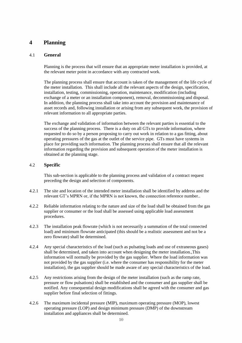
4 Planning
4.1 General
Planning is the process that will ensure that an appropriate meter installation is provided, at
the relevant meter point in accordance with any contracted work.
The planning process shall ensure that account is taken of the management of the life cycle of
the meter installation. This shall include all the relevant aspects of the design, specification,
installation, testing, commissioning, operation, maintenance, modification (including
exchange of a meter or an installation component), removal, decommissioning and disposal.
In addition, the planning process shall take into account the provision and maintenance of
asset records and, following installation or arising from any subsequent work, the provision of
relevant information to all appropriate parties.
The exchange and validation of information between the relevant parties is essential to the
success of the planning process. There is a duty on all GTs to provide information, where
requested to do so by a person proposing to carry out work in relation to a gas fitting, about
operating pressures of the gas at the outlet of the service pipe. GTs must have systems in
place for providing such information. The planning process shall ensure that all the relevant
information regarding the provision and subsequent operation of the meter installation is
obtained at the planning stage.
4.2 Specific
This sub-section is applicable to the planning process and validation of a contract request
preceding the design and selection of components.
4.2.1 The site and location of the intended meter installation shall be identified by address and the
relevant GT‟s MPRN or, if the MPRN is not known, the connection reference number..
4.2.2 Reliable information relating to the nature and size of the load shall be obtained from the gas
supplier or consumer or the load shall be assessed using applicable load assessment
procedures.
4.2.3 The installation peak flowrate (which is not necessarily a summation of the total connected
load) and minimum flowrate anticipated (this should be a realistic assessment and not be a
zero flowrate) shall be determined.
4.2.4 Any special characteristics of the load (such as pulsating loads and use of extraneous gases)
shall be determined, and taken into account when designing the meter installation.,This
information will normally be provided by the gas supplier. Where the load information was
not provided by the gas supplier (i.e. where the consumer has responsibility for the meter
installation), the gas supplier should be made aware of any special characteristics of the load.
4.2.5 Any restrictions arising from the design of the meter installation (such as the ramp rate,
pressure or flow pulsations) shall be established and the consumer and gas supplier shall be
notified. Any consequential design modifications shall be agreed with the consumer and gas
supplier before final selection of fittings.
4.2.6 The maximum incidental pressure (MIP), maximum operating pressure (MOP), lowest
operating pressure (LOP) and design minimum pressure (DMP) of the downstream
installation and appliances shall be determined.
11
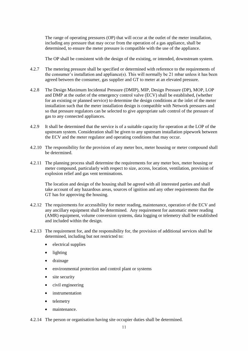
The range of operating pressures (OP) that will occur at the outlet of the meter installation,
including any pressure that may occur from the operation of a gas appliance, shall be
determined, to ensure the meter pressure is compatible with the use of the appliance.
The OP shall be consistent with the design of the existing, or intended, downstream system.
4.2.7 The metering pressure shall be specified or determined with reference to the requirements of
the consumer‟s installation and appliance(s). This will normally be 21 mbar unless it has been
agreed between the consumer, gas supplier and GT to meter at an elevated pressure.
4.2.8 The Design Maximum Incidental Pressure (DMIP), MIP, Design Pressure (DP), MOP, LOP
and DMP at the outlet of the emergency control valve (ECV) shall be established, (whether
for an existing or planned service) to determine the design conditions at the inlet of the meter
installation such that the meter installation design is compatible with Network pressures and
so that pressure regulators can be selected to give appropriate safe control of the pressure of
gas to any connected appliances.
4.2.9 It shall be determined that the service is of a suitable capacity for operation at the LOP of the
upstream system. Consideration shall be given to any upstream installation pipework between
the ECV and the meter regulator and operating conditions that may occur.
4.2.10 The responsibility for the provision of any meter box, meter housing or meter compound shall
be determined.
4.2.11 The planning process shall determine the requirements for any meter box, meter housing or
meter compound, particularly with respect to size, access, location, ventilation, provision of
explosion relief and gas vent terminations.
The location and design of the housing shall be agreed with all interested parties and shall
take account of any hazardous areas, sources of ignition and any other requirements that the
GT has for approving the housing.
4.2.12 The requirements for accessibility for meter reading, maintenance, operation of the ECV and
any ancillary equipment shall be determined. Any requirement for automatic meter reading
(AMR) equipment, volume conversion systems, data logging or telemetry shall be established
and included within the design.
4.2.13 The requirement for, and the responsibility for, the provision of additional services shall be
determined, including but not restricted to:
electrical supplies
lighting
drainage
environmental protection and control plant or systems
site security
civil engineering
instrumentation
telemetry
maintenance.
4.2.14 The person or organisation having site occupier duties shall be determined.

12
4.2.15 Any requirements that the site occupier has for “safe working” (for example permits to work,
risk assessments, method statements, authorisations, PPE etc.) shall be established.
4.2.16 Any requirement that the GT has for authorisations or approvals (for example the setting and
sealing of the regulator, by-passes and housings) shall be established and complied with.
4.2.17 Any requirement that the GT or other upstream gas conveyor has for safe working shall be
established and complied with.
4.2.18 Any requirement for continuity of supply shall be established by the MAM in consultation
with the GT, gas supplier or gas user.
4.2.19 Any restrictions imposed by the consumer in the interests of safety shall be determined (for
example the extent of any hazardous area that the consumer has identified on the premises
that may influence the choice of location of the meter installation, the type of equipment, any
restrictions on the venting of gas, etc.).
4.2.20 Deviations from recognised standards of measurement uncertainty shall be agreed between
the customer, gas supplier and GT.
4.2.21 Under GS(M)R, the GT has responsibility for establishing procedures to restore safely the gas
supply to consumers following an interruption. However, any special requirement for the
operation and maintenance of the meter installation under such circumstances shall be
established.
Table for Sub-Section 4.2: Planning - Specific
Section
Legislation
Category 1 Category 2 Category 3 Category 4
Qmax 6 m3/h
MOP 75 mbar
Standard
Installation
Qmax 6 m3/h
75 mbar < MOP
2 bar
Standard
Installation
6 m3/h < Qmax
1076 m3/h
MOP 75 mbar
Standard
Installation
Qmax > 6 m3/h
MOP 85 bar
Non-standard
Installation
4.2.1 Gas Transporter
Licence Condition
17.
4.2.2 Gas Act
Schedule 2B
Para 2(1)(b)
BS 6400 Part 1:
2002 Annex A
BS 6400 Part 2,
when published.
In the interim use
IGE/TD/15.
IGE/GM/6 IGE/GM/8
MET 1
MET 2
MET 3LS
Ofgas COP1/c
REGT 1
MET 4
CMET 1
CMET 2
4.2.3 Gas Act
Schedule 2B
Para 2(1)(b)
Business process Business process IGE/GM/6 IGE/GM/8
Ofgas COP1/c Ofgas COP1/c Ofgas COP1/c
4.2.4 Gas Act
Schedule 2B
Para 2(1)(b)
BS 6400 Part 1:
2002
IGE/TD/15 IGE/UP/2
IGE/UP/6
IGE/UP/9
IGE/UP/2
IGE/UP/6
IGE/UP/9
IGE/GM/4
Ofgas COP1/c Ofgas COP1/c

13
Section
Legislation
Category 1 Category 2 Category 3 Category 4
Qmax 6 m3/h
MOP 75 mbar
Standard
Installation
Qmax 6 m3/h
75 mbar < MOP
2 bar
Standard
Installation
6 m3/h < Qmax
1076 m3/h
MOP 75 mbar
Standard
Installation
Qmax > 6 m3/h
MOP 85 bar
Non-standard
Installation
4.2.5 GS(I&U)R Reg 38 BS 6400 Part 1:
2002
IGE/GM/6
IGE/UP/2
IGE/UP/6
IGE/GM/4
IGE/GM/8
IGE/UP/2
IGE/UP/6
Ofgas COP1/c Ofgas COP1/c
4.2.6 GS(I&U)R Reg 14
GS(M)R Reg 6(8)
BS 6400 Part 1:
2002
IGE/TD/15 IGE/GM/6 IGE/GM/8
CCN 1
CMA 1
CMA 2LS
MET 1
MET 2
MET 3LS
Ofgas COP1/c
REGT 1
CMA 1
MET 4
CMA 1
CMET 1
CMET 2
Ofgas COP1/c
4.2.7 GS(I&U)R Reg 14
GTER
GS(M)R Reg 6(8)
BS6891 BS6891 IGE/UP/2
IGE/GM/6
IGE/UP/2
IGE/GM/8
MET 1
MET 2
MET 3LS
Ofgas COP1/c
REGT 1
MET 4 CMET 1
CMET2
Ofgas COP1/c
4.2.8 GS(I&U)R Reg 14
GS(M)R Reg 6(8)
BS 6400 Part 1:
2002
IGE/TD/15. Will
be incorporated
into BS 6400 Part
2
Will be
incorporated into
IGE/GM/6
IGE/TD/4
IGE/GM/8
ACS may need to
be changed to
meet the
requirements of
BS 6400 Part 1:
2002
Ofgas COP1/c
4.2.9 GS(I&U)R Reg 14
GS(M)R Regs
6(8) & 5
BS 6400 Part 1:
2002
BS 6400 Part 2, when published. In the interim use IGE/TD/15
IGE/GM/6 IGE/GM/8
4.2.10 GS(I&U)R Reg 13
Business Process Business Process IGE/GM/6 IGE/GM/8
4.2.11 DSEAR Regs
5,6,7
GS(I&U)R Reg 13
BS 6400 Part 1:
2002
BS 6400 Part 2, when published. In the interim use IGE/TD/15
IGE/GM/6
IGE/GM/7
IGE/GM/8
IGE/GM/7
IGE/SR/25
Ofgas COP1/a Ofgas COP1/c Ofgas COP1/b Ofgas COP1/c
4.2.12 GS(I&U)R Regs
9,13 & 12
Business Process
Ofgas COP1/a Ofgas COP1/c Ofgas COP1/b Ofgas COP1/c
4.2.13 Business Process
4.2.14 HSWA s2, 3
MHSW Regs
11,12
Business Process
4.2.15 HSWA s2, 3
MHSW Regs
11,12
Business Process

14
Section
Legislation
Category 1 Category 2 Category 3 Category 4
Qmax 6 m3/h
MOP 75 mbar
Standard
Installation
Qmax 6 m3/h
75 mbar < MOP
2 bar
Standard
Installation
6 m3/h < Qmax
1076 m3/h
MOP 75 mbar
Standard
Installation
Qmax > 6 m3/h
MOP 85 bar
Non-standard
Installation
4.2.16 GS(I&U)R Regs
13 & 14
BS 6400 Part 1: BS 6400 Part 2, when published. In the interim use IGE/TD/15
Will be added to
IGE/GM/6
IGE/GM/8
4.2.18 See Annex 7

15
5 Design and the Selection of Fittings
5.1 General
Design and the selection of fittings is the process that will ensure that an appropriate meter
installation is provided and that all gas fittings will be suitable for the intended use.
5.1.1 The MAM shall ensure that its design and selection process take into account the
requirements for:
the appropriate registration of the quantity of gas conveyed through the meter installation
the provision of suitable pressure for the safe operation of appliances
the integrity of the meter installation itself
the pressure control and protection system provided to the existing or planned
downstream installation
the future maintenance of the installation.
5.1.2 The hazards and risks that the design and fittings present to persons who install, operate,
maintain or otherwise use, or require access to, the meter installation shall be considered. The
specific requirements of relevant legislation and standards must be satisfied.
5.2 Specific
The requirements of this section are applicable to the design and design validation procedures
that precede the approval, appraisal and authorisation process of other parties.
5.2.1 The meter shall be appropriate for the flow rates expected to occur in operation, taking into
account the anticipated load profile and characteristics.
5.2.2 If the meter has a maximum flowrate 1600 m3/hr at 15°C and 1013.25 mbar then it must
only be installed and used if it has been type approved and stamped (that is sealed in
accordance with Section 17 of the Gas Act 1986 as amended 1995 or European Council
Directive 71/318).
5.2.3 The accuracy of registration of the quantity of gas conveyed through the meter installation
must be determined from statutory requirements or, when enhanced accuracy is required, in
accordance with the contractual requirements.
5.2.4 The pressure control and safety system, which includes “the meter regulator”, shall ensure
that:
any downstream gas fitting (existing or intended) will not be subject to a greater pressure
than that for which it is designed
gas is supplied at a suitable pressure for safe operation of any gas appliance (existing or
intended).
5.2.5 The design of the meter installation and the specification of components must be suitable for
the intended use. The installation shall be designed in accordance with, or traceable to,
appropriate normative standards. Where no appropriate standard is available then the basis of
the design shall be validated by a competent person.
16
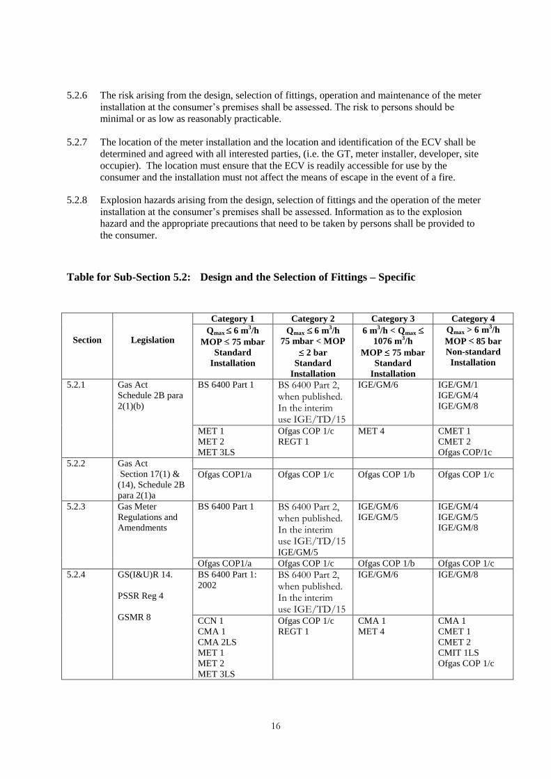
5.2.6 The risk arising from the design, selection of fittings, operation and maintenance of the meter
installation at the consumer‟s premises shall be assessed. The risk to persons should be
minimal or as low as reasonably practicable.
5.2.7 The location of the meter installation and the location and identification of the ECV shall be
determined and agreed with all interested parties, (i.e. the GT, meter installer, developer, site
occupier). The location must ensure that the ECV is readily accessible for use by the
consumer and the installation must not affect the means of escape in the event of a fire.
5.2.8 Explosion hazards arising from the design, selection of fittings and the operation of the meter
installation at the consumer‟s premises shall be assessed. Information as to the explosion
hazard and the appropriate precautions that need to be taken by persons shall be provided to
the consumer.
Table for Sub-Section 5.2: Design and the Selection of Fittings – Specific
Section
Legislation
Category 1 Category 2 Category 3 Category 4
Qmax 6 m3/h
MOP 75 mbar
Standard
Installation
Qmax 6 m3/h
75 mbar < MOP
2 bar
Standard
Installation
6 m3/h < Qmax
1076 m3/h
MOP 75 mbar
Standard
Installation
Qmax > 6 m3/h
MOP 85 bar
Non-standard
Installation
5.2.1 Gas Act
Schedule 2B para
2(1)(b)
BS 6400 Part 1 BS 6400 Part 2, when published. In the interim use IGE/TD/15
IGE/GM/6 IGE/GM/1
IGE/GM/4
IGE/GM/8
MET 1
MET 2
MET 3LS
Ofgas COP 1/c
REGT 1
MET 4 CMET 1
CMET 2
Ofgas COP/1c
5.2.2 Gas Act
Section 17(1) &
(14), Schedule 2B
para 2(1)a
Ofgas COP1/a Ofgas COP 1/c Ofgas COP 1/b Ofgas COP 1/c
5.2.3 Gas Meter
Regulations and
Amendments
BS 6400 Part 1 BS 6400 Part 2, when published. In the interim use IGE/TD/15 IGE/GM/5
IGE/GM/6
IGE/GM/5
IGE/GM/4
IGE/GM/5
IGE/GM/8
Ofgas COP1/a Ofgas COP 1/c Ofgas COP 1/b Ofgas COP 1/c
5.2.4 GS(I&U)R 14.
PSSR Reg 4
GSMR 8
BS 6400 Part 1:
2002 BS 6400 Part 2, when published. In the interim use IGE/TD/15
IGE/GM/6 IGE/GM/8
CCN 1
CMA 1
CMA 2LS
MET 1
MET 2
MET 3LS
Ofgas COP 1/c
REGT 1
CMA 1
MET 4
CMA 1
CMET 1
CMET 2
CMIT 1LS
Ofgas COP 1/c

17
Section
Legislation
Category 1 Category 2 Category 3 Category 4
Qmax 6 m3/h
MOP 75 mbar
Standard
Installation
Qmax 6 m3/h
75 mbar < MOP
2 bar
Standard
Installation
6 m3/h < Qmax
1076 m3/h
MOP 75 mbar
Standard
Installation
Qmax > 6 m3/h
MOP 85 bar
Non-standard
Installation
5.2.5 PER Reg 10
PSSR Reg 4
BS 6400 Part 1 BS 6400 Part 2, when published. In the interim use IGE/TD/15
Will be included
in IGE/GM/6
IGE/GM/8
MET 1
MET 2
MET 3LS
REGT 1 MET 4 CMET 1
CMET 2
CMIT 1LS
Ofgas COP 1/c
5.2.6 DSEAR Reg 5, 7
COSHH
BS 6400 Part 1: BS 6400 Part 2, when published. In the interim use IGE/TD/15
Ofgas COP1/a Ofgas COP 1/c Ofgas COP 1/b Ofgas COP 1/c
5.2.7 GS(I&U)R Regs 9
& 12
IGE/G/1 IGE/G/1 IGE/G/1 IGE/G/1
CCN 1
CMA 1
CMA 2LS
MET 1
MET 2
MET 3LS
Ofgas COP 1/c
REGT 1
CMA 1
MET 4
CMA 1
CMET 1
CMET 2
Ofgas COP 1/c
5.2.8 DSEAR. Regs
5,6,7,9
BS 6400 Part 1:
IGE/GM/7
BS 6400 Part 2, when published. In the interim use IGE/TD/15
IGE/SR/25
IGE/GM/7
IGE/SR/25
IGE/GM/7
MET 1
MET 2
MET 3LS
CCN 1
CMA 1
CMA 2LS
Ofgas COP 1/c
REGT 1
MET 4
CMA 1
CMET 1
CMET 2
CMA 1
18
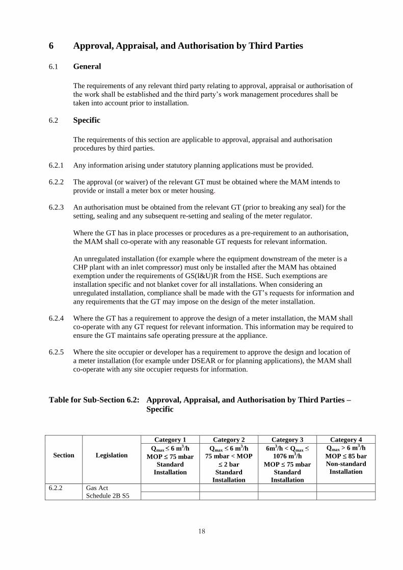
6 Approval, Appraisal, and Authorisation by Third Parties
6.1 General
The requirements of any relevant third party relating to approval, appraisal or authorisation of
the work shall be established and the third party‟s work management procedures shall be
taken into account prior to installation.
6.2 Specific
The requirements of this section are applicable to approval, appraisal and authorisation
procedures by third parties.
6.2.1 Any information arising under statutory planning applications must be provided.
6.2.2 The approval (or waiver) of the relevant GT must be obtained where the MAM intends to
provide or install a meter box or meter housing.
6.2.3 An authorisation must be obtained from the relevant GT (prior to breaking any seal) for the
setting, sealing and any subsequent re-setting and sealing of the meter regulator.
Where the GT has in place processes or procedures as a pre-requirement to an authorisation,
the MAM shall co-operate with any reasonable GT requests for relevant information.
An unregulated installation (for example where the equipment downstream of the meter is a
CHP plant with an inlet compressor) must only be installed after the MAM has obtained
exemption under the requirements of GS(I&U)R from the HSE. Such exemptions are
installation specific and not blanket cover for all installations. When considering an
unregulated installation, compliance shall be made with the GT‟s requests for information and
any requirements that the GT may impose on the design of the meter installation.
6.2.4 Where the GT has a requirement to approve the design of a meter installation, the MAM shall
co-operate with any GT request for relevant information. This information may be required to
ensure the GT maintains safe operating pressure at the appliance.
6.2.5 Where the site occupier or developer has a requirement to approve the design and location of
a meter installation (for example under DSEAR or for planning applications), the MAM shall
co-operate with any site occupier requests for information.
Table for Sub-Section 6.2: Approval, Appraisal, and Authorisation by Third Parties –
Specific
Section
Legislation
Category 1 Category 2 Category 3 Category 4
Qmax 6 m3/h
MOP 75 mbar
Standard
Installation
Qmax 6 m3/h
75 mbar < MOP
2 bar
Standard
Installation
6m3/h < Qmax
1076 m3/h
MOP 75 mbar
Standard
Installation
Qmax > 6 m3/h
MOP 85 bar
Non-standard
Installation
6.2.2 Gas Act
Schedule 2B S5

19
Section
Legislation
Category 1 Category 2 Category 3 Category 4
Qmax 6 m3/h
MOP 75 mbar
Standard
Installation
Qmax 6 m3/h
75 mbar < MOP
2 bar
Standard
Installation
6m3/h < Qmax
1076 m3/h
MOP 75 mbar
Standard
Installation
Qmax > 6 m3/h
MOP 85 bar
Non-standard
Installation
6.2.3 GS (I&U)R Reg
14
GS (I&U)R Reg
38
GS (I&U)R Reg
40
BS 6400 Part 1 BS 6400 Part 2, when published. In the interim use IGE/TD/15
IGE/GM/6 IGE/GM/8
CCN 1
CMA 1
CMA 2LS
MET 1
MET 2
MET 3LS
Ofgas COP 1/c
REGT 1
CMA 1
MET 4
CMA 1
CMET 1
CMET 2
Ofgas COP 1/c
6.2.4 GS (I&U)R Reg
14
GS (I&U)R Reg
38
GS (I&U)R Reg
40
BS 6400 Part 1 BS 6400 Part 2, when published. In the interim use IGE/TD/15
IGE/GM/6 IGE/GM/8
CCN 1
CMA 1
CMA 2LS
MET 1
MET 2
MET 3LS
Ofgas COP 1/c
REGT 1
CMA 1
MET 4
CMA 1
CMET 1
CMET 2
Ofgas COP 1/c
6.2.5 Business process
6.3 GS(M)R Safety Case
6.3.1 The Regulations are applicable to the safe and secure supply of gas through a network of
pipes and place duties on a „conveyor‟ of gas on the network.
Generally, meter installations are installed downstream of the network and the MAM would
not normally be required to produce a safety case.
6.3.2 The MAM shall determine whether the meter is installed on the Network or pipe through
which gas is conveyed to premises.
Where the meter installation forms part of the Network, the MAM should contact the gas
conveyor. If the meter installation remains on the Network, it should remain the responsibility
of the conveyor. If the MAM or other party takes ownership, the installation should be re-
engineered so that the meter is downstream of the Network and does not attract GS(M)R and
safety case duties.

20
Table for Sub-Section 6.3: Approval, Appraisal, and Authorisation by Third Parties,
(GS(M)R) Safety Case
Section
Legislation
Category 1 Category 2 Category 3 Category 4
Qmax 6 m3/h
MOP 75 mbar
Standard
Installation
Qmax 6 m3/h
75 mbar < MOP
2 bar
Standard
Installation
6m3/h < Qmax
1076 m3/h
MOP 75 mbar
Standard
Installation
Qmax > 6 m3/h
MOP 85 bar
Non-standard
Installation
6.3 GS(M)R Reg 3
GS(M)R Reg 6
IGE/GL/7
IGE/G/1
IGE/GL/7
IGE/G/1
IGE/GL/7
IGE/G/1
IGE/GL/7
IGE/G/1
21
7 Installation
7.1 General
Installation is the process that will ensure that:
any required formal notifications are made prior to commencing work
gas fittings are appropriately handled and stored
safe control of work is assured
pre-installation checks are undertaken
the installation and any ancillary equipment is installed in accordance with best practice
the installation and any ancillary equipment is inspected and tested
statutory and advisory labels are fitted.
7.2 Specific
The requirements of this section are applicable to the installation of the meter installation and
any ancillary equipment and precede commissioning.
7.2.1 Relevant formal notice of the intention to commence connection of a meter installation to, or
disconnection from, the relevant GT‟s network, or connection of meter installation
component(s) to, or disconnection from, an existing meter installation, must be made to the
relevant gas supplier. Annex 5 details information requirements.
7.2.2 Other relevant information notifications shall, as appropriate, be made to, but not be limited
to, the following parties:
HSE
local authority
relevant gas supplier
relevant GT
the site occupier
consumer
other utilities.
MAMs should additionally consider the relevant information flows required under RGMA.
7.2.3 Procedures for the safe, secure and appropriate handling and storage of all installation
components, including pipework, gas fittings, any gas meter and any tools and equipment,
shall be available and used.
7.2.4 Procedures for the safe control of work shall be available and used.
A suitably qualified person shall be nominated who shall be responsible for determining the
methods of work and the co-ordination of work activities, including means of emergency
contact, with as appropriate:
site occupier
consumer
relevant GT
22
relevant electricity distributors
other utilities.
7.2.5 All gas fittings and ancillary equipment shall be validated as being suitable for the intended
use.
The following types of documentation shall be used as appropriate to demonstrate that fittings
and ancillary equipment are suitable for the intended use:
letters of conformance
a purchase specification
material certificates
test certificates
hazardous area certification (i.e. demonstrating conformance to ATEX requirements and
CE marked as appropriate for the hazardous area)
suppliers‟ or manufacturers‟ literature.
23
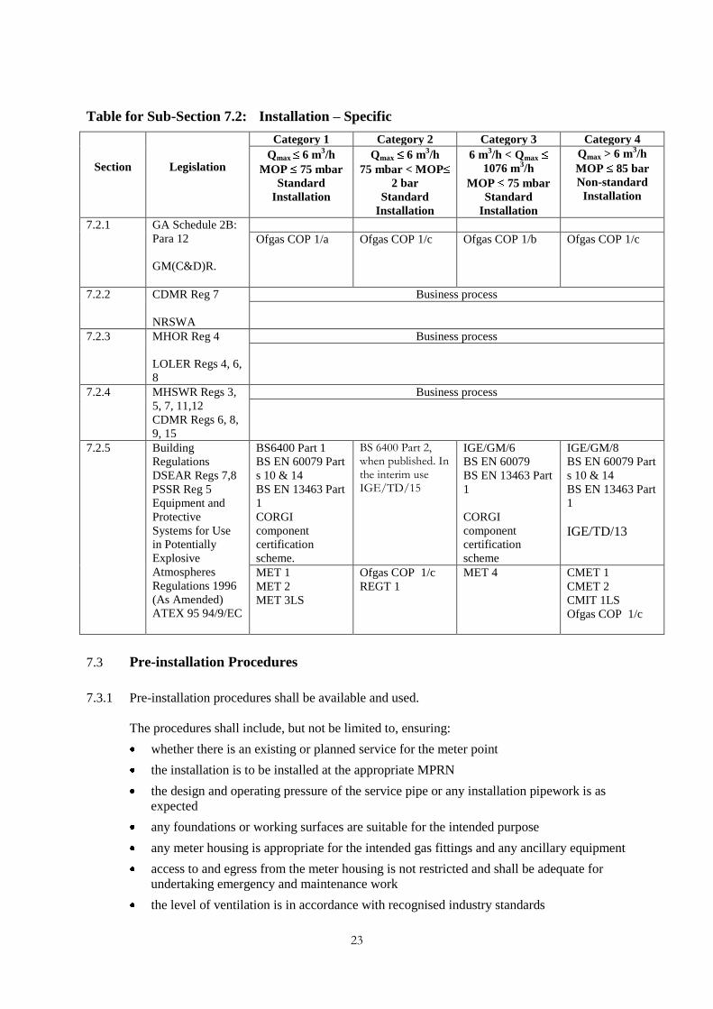
Table for Sub-Section 7.2: Installation – Specific
Section
Legislation
Category 1 Category 2 Category 3 Category 4
Qmax 6 m3/h
MOP 75 mbar
Standard
Installation
Qmax 6 m3/h
75 mbar < MOP
2 bar
Standard
Installation
6 m3/h < Qmax
1076 m3/h
MOP 75 mbar
Standard
Installation
Qmax > 6 m3/h
MOP 85 bar
Non-standard
Installation
7.2.1 GA Schedule 2B:
Para 12
GM(C&D)R.
Ofgas COP 1/a Ofgas COP 1/c Ofgas COP 1/b Ofgas COP 1/c
7.2.2 CDMR Reg 7
NRSWA
Business process
7.2.3 MHOR Reg 4
LOLER Regs 4, 6,
8
Business process
7.2.4 MHSWR Regs 3,
5, 7, 11,12
CDMR Regs 6, 8,
9, 15
Business process
7.2.5 Building
Regulations
DSEAR Regs 7,8
PSSR Reg 5
Equipment and
Protective
Systems for Use
in Potentially
Explosive
Atmospheres
Regulations 1996
(As Amended)
ATEX 95 94/9/EC
BS6400 Part 1
BS EN 60079 Part
s 10 & 14
BS EN 13463 Part
1
CORGI
component
certification
scheme.
BS 6400 Part 2, when published. In the interim use IGE/TD/15
IGE/GM/6
BS EN 60079
BS EN 13463 Part
1
CORGI
component
certification
scheme
IGE/GM/8
BS EN 60079 Part
s 10 & 14
BS EN 13463 Part
1
IGE/TD/13
MET 1
MET 2
MET 3LS
Ofgas COP 1/c
REGT 1
MET 4 CMET 1
CMET 2
CMIT 1LS
Ofgas COP 1/c
7.3 Pre-installation Procedures
7.3.1 Pre-installation procedures shall be available and used.
The procedures shall include, but not be limited to, ensuring:
whether there is an existing or planned service for the meter point
the installation is to be installed at the appropriate MPRN
the design and operating pressure of the service pipe or any installation pipework is as
expected
any foundations or working surfaces are suitable for the intended purpose
any meter housing is appropriate for the intended gas fittings and any ancillary equipment
access to and egress from the meter housing is not restricted and shall be adequate for
undertaking emergency and maintenance work
the level of ventilation is in accordance with recognised industry standards

24
the local environment in the vicinity of the meter installation does not have or introduce
any hazard that will compromise the safe and effective operation and use of the meter
installation
the risk from electricity is assessed and that correct earthing and equipotential bonding is
maintained at all times within the consumer‟s premises, for example through the use of a
temporary continuity bond
fittings and all necessary equipment are suitable for the intended use
information on the service labelling is considered.
Table for Sub-Section 7.3: Installation - Pre-installation procedures
Section
Legislation
Category 1 Category 2 Category 3 Category 4
Qmax 6 m3/h
MOP 75 mbar
Standard
Installation
Qmax 6 m3/h
75 mbar < MOP
2 bar
Standard
Installation
6 m3/h < Qmax
1076 m3/h
MOP 75 mbar
Standard
Installation
Qmax > 6 m3/h
MOP 85 bar
Non-standard
Installation
7.3.1 DSEAR Regs
5,6,7
GSIUR Regs
10,12 & 13
BS6400 Part 1
CCN 1
CMA 1
CMA 2LS
MET 1
MET 2
MET 3LS
Ofgas COP 1/c
REGT 1
CMA 1
MET 4
CMA 1
CMET 1
CMET 2
CMIT 1LS
Ofgas COP 1/c
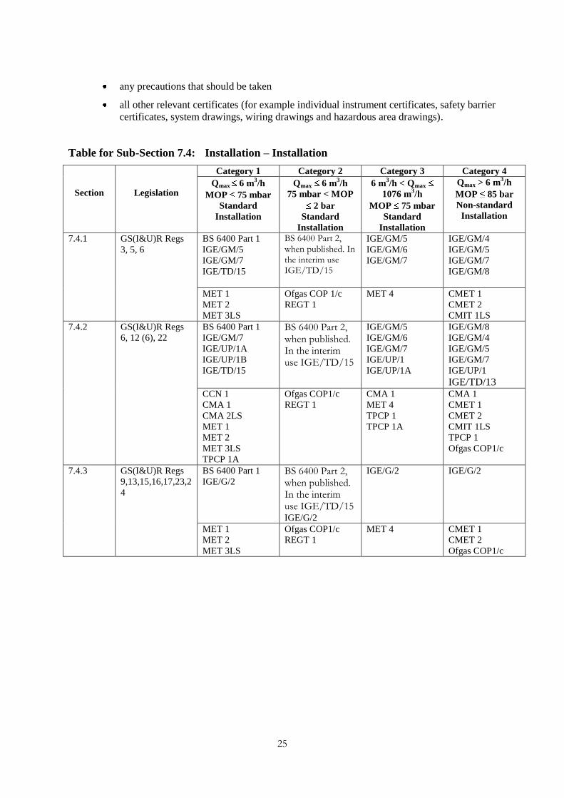
7.4 Installation
7.4.1 The meter installation shall be installed by appropriately qualified and competent persons in
accordance with best practice, relevant normative standards, manufacturers‟ information and
appropriate installer‟s field procedures.
7.4.2 Tests shall be undertaken that assure the integrity of fittings, associated pipework, any
ancillary equipment and electrical and instrumentation systems.
7.4.3 Notices and labels must be fitted in accordance with the relevant legislation and shall be in
accordance with standards and any conditions arising from the approval or authorisation by
third parties. Appropriate technical information shall be made available to persons
undertaking subsequent work activities. This shall include, but not be limited to, information
regarding:
the design, installation and intended use of the installation and any ancillary equipment
the installation peak flow rate for which the meter has been designed (refer to 4.2.3)
the metering pressure
the voltage and rating of electrical and instrument equipment and systems
the status of the installation with respect to any isolations or precautions arising from safe
control of work procedures
any hazards associated with the use of the installation
25
any precautions that should be taken
all other relevant certificates (for example individual instrument certificates, safety barrier
certificates, system drawings, wiring drawings and hazardous area drawings).
Table for Sub-Section 7.4: Installation – Installation
Section
Legislation
Category 1 Category 2 Category 3 Category 4
Qmax 6 m3/h
MOP 75 mbar
Standard
Installation
Qmax 6 m3/h
75 mbar < MOP
2 bar
Standard
Installation
6 m3/h < Qmax
1076 m3/h
MOP 75 mbar
Standard
Installation
Qmax > 6 m3/h
MOP 85 bar
Non-standard
Installation
7.4.1 GS(I&U)R Regs
3, 5, 6
BS 6400 Part 1
IGE/GM/5
IGE/GM/7
IGE/TD/15
BS 6400 Part 2, when published. In the interim use IGE/TD/15
IGE/GM/5
IGE/GM/6
IGE/GM/7
IGE/GM/4
IGE/GM/5
IGE/GM/7
IGE/GM/8
MET 1
MET 2
MET 3LS
Ofgas COP 1/c
REGT 1
MET 4 CMET 1
CMET 2
CMIT 1LS
7.4.2 GS(I&U)R Regs
6, 12 (6), 22
BS 6400 Part 1
IGE/GM/7
IGE/UP/1A
IGE/UP/1B
IGE/TD/15
BS 6400 Part 2, when published. In the interim use IGE/TD/15
IGE/GM/5
IGE/GM/6
IGE/GM/7
IGE/UP/1
IGE/UP/1A
IGE/GM/8
IGE/GM/4
IGE/GM/5
IGE/GM/7
IGE/UP/1
IGE/TD/13
CCN 1
CMA 1
CMA 2LS
MET 1
MET 2
MET 3LS
TPCP 1A
Ofgas COP1/c
REGT 1
CMA 1
MET 4
TPCP 1
TPCP 1A
CMA 1
CMET 1
CMET 2
CMIT 1LS
TPCP 1
Ofgas COP1/c
7.4.3 GS(I&U)R Regs
9,13,15,16,17,23,2
4
BS 6400 Part 1
IGE/G/2 BS 6400 Part 2, when published. In the interim use IGE/TD/15
IGE/G/2
IGE/G/2 IGE/G/2
MET 1
MET 2
MET 3LS
Ofgas COP1/c
REGT 1
MET 4 CMET 1
CMET 2
Ofgas COP1/c

26
8 Modifications
8.1 General
The MAM may be required to modify meter installations for which it is responsible. This
may arise as a result of requests, through recognised contractual arrangements, from the GT,
gas supplier or consumer. The need may also arise from the MAM‟s own arrangements for
keeping installations in proper order.
8.2 Specific
The requirements of this section are applicable to modifications of a meter installation.
8.3 Meter Housing
The suitability of the housing, irrespective of final ownership, shall be verified as part of the
assessment of work required. The appropriate party should be notified of any changes or
modifications required to the meter housing.
Table for Sub-Section 8.3: Modifications – Meter Housing
Section
Legislation
Category 1 Category 2 Category 3 Category 4
Qmax 6 m3/h
MOP 75 mbar
Standard
Installation
Qmax 6 m3/h
75 mbar < MOP
2 bar
Standard
Installation
6 m3/h < Qmax
1076 m3/h
MOP 75 mbar
Standard
Installation
Qmax > 6 m3/h
MOP 85 bar
Non-standard
Installation
8.3 Gas Act Schedule
2B: s 5
8.4 Notification
In the event that any modification to the meter installation, covered in sub-sections 8.5 to 8.9,
that requires the installation to be disconnected, relevant formal notification should be given
in accordance with sub-sections 7.2.1 and 7.2.2.
Table for Sub-Section 8.4: Modifications – Formal Notification
Section
Legislation
Category 1 Category 2 Category 3 Category 4
Qmax 6 m3/h
MOP 75 mbar
Standard
Installation
Qmax 6 m3/h
75 mbar < MOP
2 bar
Standard
Installation
6 m3/h < Qmax
1076 m3/h
MOP 75 mbar
Standard
Installation
Qmax > 6 m3/h
MOP 85 bar
Non-standard
Installation
8.4 Gas Act Schedule
2B: s 12
GM(C&D)R.
CDMR R 7
NRSWA
Ofgas COP1/a Ofgas COP1/c Ofgas COP1/b Ofgas COP1/c

27
8.5 Policy Meter or Component Exchange
8.5.1 A meter or component may need to be exchanged for a number of reasons, (for example fault,
end of life, or change of circumstances of the gas consumer).
8.5.2 Where a type of meter or component is recalled by the MAM for safety or other reasons, an
initial risk assessment shall be undertaken to establish the type of exchange policy to be
adopted.
8.5.3 Where a MAM implements an exchange policy for safety or other reasons, the MAM shall
inform the component manufacturer that an exchange policy has been implemented and the
reasons for doing so.
8.5.4 For all installations, the load details can be obtained from the gas supplier. Alternatively, a
load assessment shall be performed prior to undertaking any exchange work to determine the
appropriateness of the meter and its installation components.
8.6 Credit or Pre-payment Meter Exchange
8.6.1 Where an exchange of credit for pre-payment meter is required, it shall be established that the
location is suitable for a pre-payment meter (that is, it is readily accessible by the consumer
for appending credit to the meter).
8.6.2 A pre-payment meter shall not be fitted as a primary meter if there is a secondary meter used
to render a charge to a consumer on its downstream side.
Table for Sub-Section 8.6: Modifications – Credit or Pre-payment Meter Exchange
Section
Legislation
Category 1 Category 2 Category 3 Category 4
Qmax 6 m3/h
MOP 75 mbar
Standard
Installation
Qmax 6 m3/h
75 mbar < MOP
2 bar
Standard
Installation
6 m3/h < Qmax
1076 m3/h
MOP 75 mbar
Standard
Installation
Qmax > 6 m3/h
MOP 85 bar
Non-standard
Installation
8.6.2 GS(I&U)R Reg 16
(1)
Ofgas COP1/a Ofgas COP1/c Ofgas COP1/b Ofgas COP1/c
8.7 Unsuitable Installations
8.7.1 Installations may be deemed to be unsuitable. The following list, which is not exhaustive,
provides specific examples where consideration is required.
safety or integrity of the installation
access to the ECV
accessibility to read the meter
accessibility to maintain the meter installation
accessibility to exchange the meter
proximity and suitability of electrical equipment
property alterations
inappropriate or unsuitable by-pass arrangements
inadequate ventilation
28
suitability for the load
installation of, or alteration to, third party equipment
unapproved equipment connected to the installation.
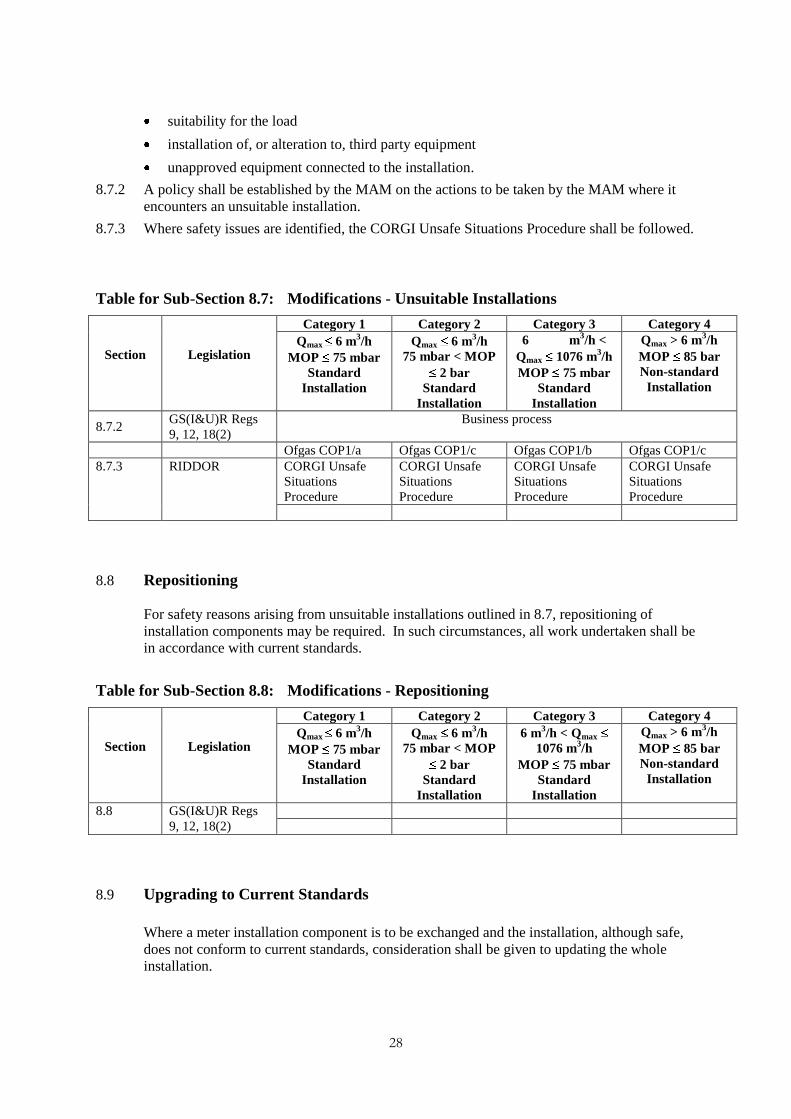
8.7.2 A policy shall be established by the MAM on the actions to be taken by the MAM where it
encounters an unsuitable installation.
8.7.3 Where safety issues are identified, the CORGI Unsafe Situations Procedure shall be followed.
Table for Sub-Section 8.7: Modifications - Unsuitable Installations
Section
Legislation
Category 1 Category 2 Category 3 Category 4
Qmax 6 m3/h
MOP 75 mbar
Standard
Installation
Qmax 6 m3/h
75 mbar < MOP
2 bar
Standard
Installation
6 m3/h <
Qmax 1076 m3/h
MOP 75 mbar
Standard
Installation
Qmax > 6 m3/h
MOP 85 bar
Non-standard
Installation
8.7.2 GS(I&U)R Regs
9, 12, 18(2)
Business process
Ofgas COP1/a Ofgas COP1/c Ofgas COP1/b Ofgas COP1/c
8.7.3 RIDDOR CORGI Unsafe
Situations
Procedure
CORGI Unsafe
Situations
Procedure
CORGI Unsafe
Situations
Procedure
CORGI Unsafe
Situations
Procedure
8.8 Repositioning
For safety reasons arising from unsuitable installations outlined in 8.7, repositioning of
installation components may be required. In such circumstances, all work undertaken shall be
in accordance with current standards.
Table for Sub-Section 8.8: Modifications - Repositioning
Section
Legislation
Category 1 Category 2 Category 3 Category 4
Qmax 6 m3/h
MOP 75 mbar
Standard
Installation
Qmax 6 m3/h
75 mbar < MOP
2 bar
Standard
Installation
6 m3/h < Qmax
1076 m3/h
MOP 75 mbar
Standard
Installation
Qmax > 6 m3/h
MOP 85 bar
Non-standard
Installation
8.8 GS(I&U)R Regs
9, 12, 18(2)
8.9 Upgrading to Current Standards
Where a meter installation component is to be exchanged and the installation, although safe,
does not conform to current standards, consideration shall be given to updating the whole
installation.

29
Table for Sub-Section 8.9: Modifications - Upgrading to Current Standards
Section
Legislation
Category 1 Category 2 Category 3 Category 4
Qmax 6 m3/h
MOP 75 mbar
Standard
Installation
Qmax 6 m3/h
75 mbar < MOP
2 bar
Standard
Installation
6 m3/h < Qmax
1076 m3/h
MOP 75 mbar
Standard
Installation
Qmax > 6 m3/h
MOP 85 bar
Non-standard
Installation
8.9 MHSWR Reg 3 Business process
Ofgas COP1/a Ofgas COP1/c Ofgas COP1/b Ofgas COP1/c
8.10 Ancillary Replacement (for example converters, AMR, etc…)
8.10.1 MAMs shall be aware of the requirements for, and the effect of, any other equipment which is
to interface with the meter installation (for example converters).
8.10.2 Records shall be maintained of ancillary equipment connected to the MAM‟s meters.
8.10.3 When replacing or installing ancillary equipment, the MAM shall ensure:
ancillary equipment connected to the meter is installed to appropriate standards
ancillary equipment connected to the meter installation is undertaken by appropriately
trained and competent operatives
that following the fitting of ancillary equipment to the meter installation, all relevant
information is communicated to interested parties in the supply chain.
8.10.4 In the event that a third party requests permission to connect ancillary equipment to a meter
installation, the MAM shall:
specify the appropriate standards to which the equipment is to be installed
require that appropriately trained and qualified operatives undertake the work
respond to the request in writing either granting permission or explaining why permission
is withheld.

30
Table for Sub-Section 8.10: Modifications - Ancillary Replacement (for example
converters, AMR, etc...)
Section
Legislation
Category 1 Category 2 Category 3 Category 4
Qmax 6 m3/h
MOP 75 mbar
Standard
Installation
Qmax 6 m3/h
75 mbar < MOP
2 bar
Standard
Installation
6 m3/h < Qmax
1076 m3/h
MOP 75 mbar
Standard
Installation
Qmax > 6 m3/h
MOP 85 bar
Non-standard
Installation
8.10.1 DSEAR Regs 5,6
BS 6400 Part 1
BS EN60079 Part
14
IGE/GM/5
IGE/GM/7
BS 6400 Part 2, when published. In the interim use IGE/TD/15
BS EN60079 Part
14
IGE/GM/5
IGE/GM/7
BS EN60079 Part
14
IGE/GM/5
IGE/GM/6
IGE/GM/7
BS EN60079 Part
14
IGE/GM/4
IGE/GM/5
IGE/GM/7
IGE/GM/8
IGE/SR/25
Ofgas COP1/c Ofgas COP1/b Ofgas COP1/c
8.10.2 DSEAR R6,7
ATEX 95 94/9/EC
CAD
98/24/EC
EWR Reg 4
BS 6400 Part 1
BS EN60079 Part
14
IGE/GM/5
IGE/GM/7
BS 6400 Part 2, when published. In the interim use IGE/TD/15
BS EN60079 Part
14
IGE/GM/5
IGE/GM/7
BS EN60079 Part
14
IGE/GM/5
IGE/GM/6
IGE/GM/7
BS EN60079 Part
14
IGE/GM/1
IGE/GM/4
IGE/GM/5
IGE/GM/7
IGE/GM/8
IGE/SR/25
8.10.3 DSEAR Regs 6,7
GSIUR Reg 12
ATEX 95 94/9/EC
ATEX137
99/92/EC
CAD
98/24/EC
EWR Regs 4,16
BS 6400 Part 1
BS EN60079 Part
14
IGE/GM/5
IGE/GM/7
BS 6400 Part 2, when published. In the interim use IGE/TD/15
BS EN60079 Part
14
IGE/GM/5
IGE/GM/7
BS EN60079 Part
14
IGE/GM/5
IGE/GM/6
IGE/GM/7
BS EN60079 Part
14
IGE/GM/4
IGE/GM/5
IGE/GM/7
IGE/GM/8
IGE/SR/25
Ofgas COP1/a Ofgas COP1/c Ofgas COP1/b Ofgas COP1/c

31
9 Commissioning
9.1 General
Commissioning ensures that a meter installation operates as intended and within defined
parameters.
Table for Sub-Section 9.1: Commissioning – General
Section
Legislation
Category 1 Category 2 Category 3 Category 4
Qmax 6 m3/h
MOP 75 mbar
Standard
Installation
Qmax 6 m3/h
75 mbar < MOP
2 bar
Standard
Installation
6 m3/h < Qmax
1076 m3/h
MOP 75 mbar
Standard
Installation
Qmax > 6 m3/h
MOP 85 bar
Non-standard
Installation
9.1 GS(I&U)R Reg
12(6)
BS6400 Part1
2002
IGE/UP/1b
BS 6400 Part 2, when published. In the interim use IGE/TD/15
IGE/UP/1B
IGE/GM/6
IGE/UP/1A
IGE/UP/1
MET 1
MET 2
MET 3LS
Ofgas COP1/c
REGT 1
CMET 1
MET 4
MET 4
CMET 1
CMET 2
9.2 Specific
The requirements of this section cover the commissioning of flow metering systems. It is
specialised and is specific to site, product and procedure. However, in the case of small low
pressure installations it may be possible to utilise a more generic approach.
9.2.1 Where a MAM has a responsibility to restore a gas supply following work on the meter
installation, any re-commissioning of the downstream system shall be undertaken in
accordance with the appropriate industry standards.
9.2.2 Commissioning procedures shall be developed and shall take into account as appropriate, the
requirements of:
legislation
manufacturer‟s instructions
British Standards
European Standards
International Standards
registration bodies (for example CORGI)
professional institutions (for example IGEM)
industry (GT, gas supplier or shipper etc.)
customer-specific requirements.
32
9.2.3 The commissioning of a meter installation shall not be undertaken unless normal gas service
pressure is available at the time.
9.2.4 The proposed work schedule and timescales shall be agreed with the consumer or responsible
person.
9.3 Pre-commissioning Checks 9.3.1 Any pre-initialisation procedures, which may be required in accordance with the
manufacturer's instructions, shall be carried out.
9.3.2 It shall be ensured that the correct meter installation is being commissioned, by confirming,
where available, the following:
consumer name
the GT
the MPRN
the meter point address
meter serial number
shipper and/or gas supplier details.
9.3.3 It shall be ensured that any relevant installation test certificates are available. These should
include but not be limited to:
installation completion certificates
pressure test certificates
tightness test certificate
non-destructive testing (NDT) certificates
electrical test certificates
handover certificates.
9.4 Physical Pre-commissioning Checks on the Installation
9.4.1 The installation shall be subject to physical pre-commissioning checks as follows to ensure:
(a) any pressure tappings are located correctly and there are suitable test points provided
to enable verification of the supply pressure, metering pressure and installation outlet
pressure
(b) there are adequate purge and vent points to enable strength and tightness testing and
purging to be undertaken in a safe manner
(c) the supply pressure is verified
(d) any vent stack terminations are in a suitable location, given the extent of any
hazardous area generated, proximity to buildings, etc.
(e) there are no detectable gas leaks from the meter installation
(f) any wiring terminations to the conversion devices, associated pressure transducer and
temperature sensor are in accordance with the manufacturer's instructions
(g) any electrical equipment and instrumentation is certified for the hazardous area zone
in which it has been installed
(h) any electrical equipment and instrumentation has been installed taking into account
the requirements of the hazardous area equipment certificates

33
(i) the installation requirements detailed in Section 7 of the MAMCoP have been
followed
all relevant labels have been correctly attached, and where applicable a gas supply line diagram of the
consumer‟s installation is in place.
Table for Sub-Section 9.4: Physical Pre-commissioning Checks on the Installation
Section
Legislation
Category 1 Category 2 Category 3 Category 4
Qmax 6 m3/h
MOP 75 mbar
Standard
Installation
Qmax 6 m3/h
75 mbar < MOP
2 bar
Standard
Installation
6 m3/h < Qmax
1076 m3/h
MOP 75 mbar
Standard
Installation
Qmax > 6 m3/h
MOP 85 bar
Non-standard
Installation
9.4.1 (a) BS 6400 Part 1
2002
BS 6400 Part 2, when published. In the interim use IGE/TD/15
IGE/GM/6 IGE/GM/8
9.4.1 (b) GS(I&U)R Reg
6(1)
BS 6400 Part 1
2002
BS 6400 Part 2, when published. In the interim use IGE/TD/15
IGE/GM/6 IGE/GM/8
9.4.1 (c) GS(I&U)R Reg 14 BS 6400 Part 1
2002
BS 6400 Part 2, when published. In the interim use IGE/TD/15
IGE/GM/6 IGE/GM/8
Ofgas COP/1a Ofgas COP1/c Ofgas COP1/b Ofgas COP1/c
9.4.1 (d) GS(I&U)R Reg
6(1)
IGE/GM/7
IGE/UP/1B
IGE/GM/7
IGE/UP/1B
IGE/GM/7
IGE/UP/1A
IGE/GM/7
IGE/UP/1
MET 1
MET 2
MET 3LS
Ofgas COP1/c
REGT 1
MET 4 CMET 1
CMET 2
Ofgas COP1/c
9.4.1 (e) GS(I&U)R Regs
6(6), 12 (6)
IGE/UP/1B IGE/UP/1B IGE/UP/1A
IGE/UP/1
IGE/UP/1
MET 1
MET 2
MET 3LS
Ofgas COP1/c
REGT 1
TPCP 1A
TPCP 1
TPCP 1
9.4.1 (f) IGE/GM/7 IGE/GM/7 IGE/GM/7
IGE/GM/5
IGE/GM/7
IGE/GM/5
MET 1
MET 2
MET 3LS
REGT 1 MET 4
TPCP 1
TPCP 1A
CMET 1
CMET 2
TPCP 1
9.4.1 (g) DSEAR IGE/GM/7 IGE/GM/7 IGE/GM/7 IGE/GM/7
9.4.1 (h) DSEAR IGE/GM/7 IGE/GM/7 IGE/GM/7 IGE/GM/7

34
9.4.1 (j) GS(I&U)R Regs
15, 16(2), 17 IGE/G/2 IGE/UP/2
BS 6400 Part 1
IGE/G/2
IGE/TD/15 BS 6400 Part 2, when published. In the interim use IGE/TD/15 IGE/UP/2
IGE/UP/2
IGE/UP/2
I GE/G/2
MET 1
MET 2
MET 3LS
REGT 1 MET 4 CMET 1
CMET 2
Ofgas COP1/c
35
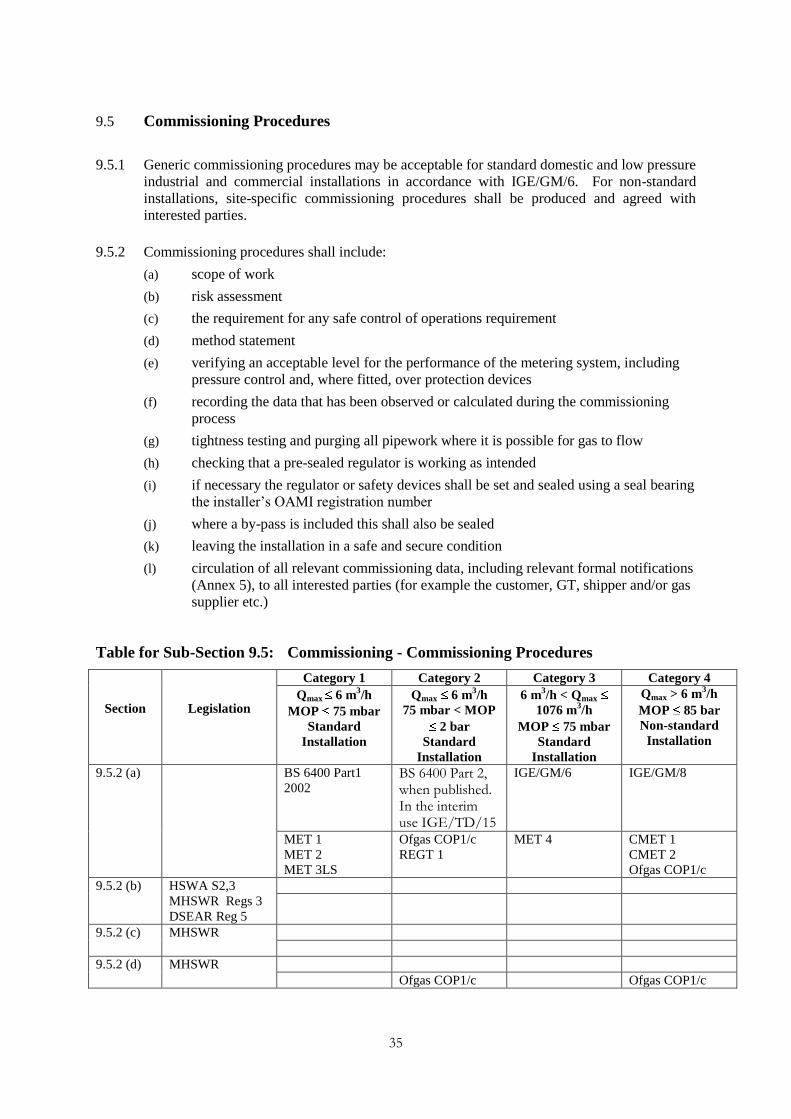
9.5 Commissioning Procedures
9.5.1 Generic commissioning procedures may be acceptable for standard domestic and low pressure
industrial and commercial installations in accordance with IGE/GM/6. For non-standard
installations, site-specific commissioning procedures shall be produced and agreed with
interested parties.
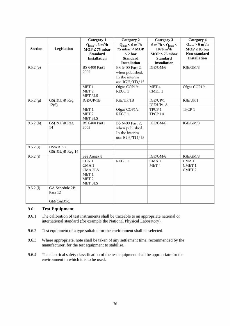
9.5.2 Commissioning procedures shall include:
(a) scope of work
(b) risk assessment
(c) the requirement for any safe control of operations requirement
(d) method statement
(e) verifying an acceptable level for the performance of the metering system, including
pressure control and, where fitted, over protection devices
(f) recording the data that has been observed or calculated during the commissioning
process
(g) tightness testing and purging all pipework where it is possible for gas to flow
(h) checking that a pre-sealed regulator is working as intended
(i) if necessary the regulator or safety devices shall be set and sealed using a seal bearing
the installer‟s OAMI registration number
(j) where a by-pass is included this shall also be sealed
(k) leaving the installation in a safe and secure condition
(l) circulation of all relevant commissioning data, including relevant formal notifications
(Annex 5), to all interested parties (for example the customer, GT, shipper and/or gas
supplier etc.)
Table for Sub-Section 9.5: Commissioning - Commissioning Procedures
Section
Legislation
Category 1 Category 2 Category 3 Category 4
Qmax 6 m3/h
MOP 75 mbar
Standard
Installation
Qmax 6 m3/h
75 mbar < MOP
2 bar
Standard
Installation
6 m3/h < Qmax
1076 m3/h
MOP 75 mbar
Standard
Installation
Qmax > 6 m3/h
MOP 85 bar
Non-standard
Installation
9.5.2 (a)
BS 6400 Part1
2002 BS 6400 Part 2, when published. In the interim use IGE/TD/15
IGE/GM/6 IGE/GM/8
MET 1
MET 2
MET 3LS
Ofgas COP1/c
REGT 1
MET 4 CMET 1
CMET 2
Ofgas COP1/c
9.5.2 (b) HSWA S2,3
MHSWR Regs 3
DSEAR Reg 5
9.5.2 (c) MHSWR
9.5.2 (d) MHSWR
Ofgas COP1/c Ofgas COP1/c
36
Section
Legislation
Category 1 Category 2 Category 3 Category 4
Qmax 6 m3/h
MOP 75 mbar
Standard
Installation
Qmax 6 m3/h
75 mbar < MOP
2 bar
Standard
Installation
6 m3/h < Qmax
1076 m3/h
MOP 75 mbar
Standard
Installation
Qmax > 6 m3/h
MOP 85 bar
Non-standard
Installation
9.5.2 (e) BS 6400 Part1
2002 BS 6400 Part 2, when published. In the interim use IGE/TD/15
IGE/GM/6 IGE/GM/8
MET 1
MET 2
MET 3LS
Ofgas COP1/c
REGT 1
MET 4
CMET 1
Ofgas COP1/c
9.5.2 (g) GS(I&U)R Reg
12(6),
IGE/UP/1B IGE/UP/1B IGE/UP/1
IGE/UP/1A
IGE/UP/1
MET 1
MET 2
MET 3LS
Ofgas COP1/c
REGT 1
TPCP 1
TPCP 1A
TPCP 1
9.5.2 (h) GS(I&U)R Reg
14
BS 6400 Part1
2002 BS 6400 Part 2, when published. In the interim use IGE/TD/15
IGE/GM/6 IGE/GM/8
9.5.2 (i) HSWA S3,
GS(I&U)R Reg 14
9.5.2 (j) See Annex 8 IGE/GM/6 IGE/GM/8
CCN 1
CMA 1
CMA 2LS
MET 1
MET 2
MET 3LS
REGT 1 CMA 1
MET 4
CMA 1
CMET 1
CMET 2
9.5.2 (l) GA Schedule 2B:
Para 12
GM(C&D)R.
9.6 Test Equipment
9.6.1 The calibration of test instruments shall be traceable to an appropriate national or
international standard (for example the National Physical Laboratory).
9.6.2 Test equipment of a type suitable for the environment shall be selected.
9.6.3 Where appropriate, note shall be taken of any settlement time, recommended by the
manufacturer, for the test equipment to stabilise.
9.6.4 The electrical safety classification of the test equipment shall be appropriate for the
environment in which it is to be used.

37
Table for Sub-Section 9.6: Commissioning – Test Equipment
Section
Legislation
Category 1 Category 2 Category 3 Category 4
Qmax 6 m3/h
MOP 75 mbar
Standard
Installation
Qmax 6 m3/h
75 mbar < MOP
2 bar
Standard
Installation
6 m3/h < Qmax
1076 m3/h
MOP 75 mbar
Standard
Installation
Qmax > 6 m3/h
MOP 85 bar
Non-standard
Installation
9.6.4 DSEAR Regs 6,7
IGE/UP/1B
IGE/GM/7
IGE/UP/1B
IGE/GM/7
IGE/UP/1A
IGE/GM/7
IGE/UP/1
IGE/GM/7

38
10 Provision of Information
10.1 General
Information relevant to the safe and efficient operation of the meter installation and to the
commercial processes that support the supply of gas to a consumer shall be made available to
the appropriate persons.
10.2 Specific
The requirements of this section cover disclosure, communication and flows of information
(see also RGMA Processes & Data for industry standards) related to a meter installation.
10.3 Availability of Capacity and Pressure Information
Information regarding the capacity and operational pressure limits that may occur at the outlet
of the meter installation shall be made available at the installation, for use by the consumer or
other persons who may undertake work on the downstream system.
The MAM shall provide, as a minimum, the following:
the installation peak flow rate for which the meter has been designed (refer to 4.2.3)
the meter pressure
the settings of any pressure protection or pressure control devices, such as slam-shut
valves or relief valves
MIP at the outlet of the meter installation
MOP at the outlet of the meter installation.
10.4 Description of Installation
Where the MAM acts on behalf of the gas supplier with which it is contracted with regard to
Regulations 15 and 17 of the GS(I&U)R or in other appropriate circumstances, the MAM
shall provide, for use by the consumer and emergency service provider, a description of the
installation that shall include an explanation as to how the installation is isolated, made safe
and labelled in accordance with Regulations 15 and 17 of the GS(I&U)R. The description
shall be updated as necessary.
Where known by the MAM, the MAM should ensure the consumer is aware of any parts of
the meter installation which the consumer owns. The owner of a meter housing must ensure it
remains accessible and properly maintained.
10.5 Gas Meters (Information on Connection and Disconnection) Regulations
At the time of connection or disconnection, the data on the meter installation shall be
communicated in the requisite timescales to the parties named in the GM(C&D)R (Annex 5).
39
10.6 Dangerous Substances and Explosive Atmospheres Regulations (DSEAR) and
Control of Substances Hazardous to Health Regulations (COSHH)
Where within the meter installation substances and materials have been used which require
notification in accordance with DSEAR and COSHH, the MAM should cooperate with the
consumer to provide any appropriate information to enable the consumer to comply with these
Regulations.
10.7 Gas (Calculation of Thermal Energy) Regulations
The MAM shall calculate the volume conversion factor for the meter installation in
accordance with the requirements of the Gas (Calculation of Thermal Energy) Regulations
(GTER) and amendment and provide this with the relevant information in sub-section 10.5, to
the gas supplier.
10.8 Other Commercial Data Flow
Where a meter installation belonging to one MAM is replaced by an installation belonging to
another MAM, all appropriate information consistent with the RGMA baseline shall be
communicated by the MAM carrying out the replacement.

40
11 Operation
11.1 General
Appropriate operation of a meter installation ensures that all equipment functions as intended when
in normal use.
11.2 Specific
The requirements of this section cover operational procedures related to a meter installation.
11.2.1 The operation of the meter installation must be conducted in accordance with relevant legislation
listed in Annex 3. Operation of the meter installation shall be conducted in accordance with agreed
procedures that conform to the requirements of :
procedures for reporting and dealing with gas escapes
Network Codes
recognised industry standards
the GT‟s safe control of operations procedures
any safe control of operations procedures operated by the consumer or site owner
Information resulting from such activities can be sent to interested market participants using the
standard flows defined in RGMA Processes and Data.
11.2.2 Additionally, the following requirements apply:
all procedures should be produced and audited to a quality system in accordance with sub-
section 3.5.
in operating the meter installation, the responsibilities of each interested party shall be defined
or identified.
11.3 Normal and Planned Operational Activities
The MAM shall develop procedures to manage the operation of a meter installation arising from
planned work undertaken by the MAM. The procedures shall include, but not be limited to:
commissioning of the meter installation
the control and operation of any meter by-pass (see Annex 7)
maintenance activities
safety or statutory inspections
the temporary disconnection and connection of the meter installation
isolation of the meter installation.
11.4 Unplanned Operational Activities
Procedures shall be developed to manage unplanned events that may affect the operation of the
installation. The procedures shall include but not be limited to:
general enquiries by the consumer or persons acting on their behalf (for example capacity
inquiries or pressure problems)
meter accuracy or meter reading disputes including any requests for an Ofgem accuracy test

41
other disputes (for example pressure related disputes)
theft of gas incidents
operation of the bypass
installation operational faults (for example, inadvertent operation of safety devices)
gas supply incidents associated with the operation of the gas network (for example water
ingress, network overpressure or loss of gas supply), including operation of the flow limiter
cooperation in the investigation of carbon monoxide (CO) emission and other incidents.

42
12 Maintenance
12.1 General
Maintenance is the process that will ensure that the meter installation is kept in proper
working order, that safety is not compromised and that the installation continues to correctly
record the quantity of gas conveyed. Maintenance activities generally fall into one of three
categories:
planned preventative maintenance
fault maintenance or repair
planned replacement of components.
12.2 Maintenance Procedures
The requirements of this section cover the maintenance of a meter installation.
Standards for related information flows are covered in the RGMA Processing and Data
documents.
12.2.1 Procedures shall be developed to ensure that appropriate maintenance is undertaken by
suitably trained and competent persons. The procedures shall include, but not be limited to,
ensuring that:
(a) maintenance procedures are applicable to the specific installation and that the correct
installation is being maintained
(b) arrangements have been made for safe access, egress and adequate working space
(c) risk assessments are available for the work intended
(d) any requirements of the relevant GT, gas supplier, consumer and/or site occupier are
included in the work place instructions and/or safe control of operations procedures
(e) the risk from electricity is assessed and that correct earthing and equipotential
bonding is maintained at all times within the consumer‟s premises (for example
through the use of a temporary continuity bond)
(f) if any component needs to be replaced, the replacement component should comply
with all requirements, be fit for purpose and approved for use in the meter
installation.
12.2.2 The MAM shall ensure that appropriate maintenance is undertaken to ensure that:
(a) the whole installation is kept in proper working order
(b) safety is not compromised
(c) the installation continues to record and control correctly the quantity of gas
conveyed.
12.2.3 Maintenance records shall be kept. These shall include:
(a) the type of the maintenance (for example planned, fault or planned replacement)
(b) a description of the work carried out
(c) the meter serial numbers and (where appropriate) readings at the start and end of the
maintenance activity

43
(d) the name of the person(s) who undertook the work
(e) the date(s) the maintenance work was carried out
(f) a description of any other work identified as being necessary and the date by which it
should be completed
(g) any by-pass operation details and times, in accordance with Network Code.
12.2.4 Maintenance records shall be kept for the life of the asset.
12.2.5 Where a metering system is installed in a hazardous area, maintenance shall be undertaken so
as not to jeopardise the integrity of the protection classification of the metering system. If any
component of the metering system or meter housing needs to be replaced, a risk assessment
shall be undertaken to determine whether to replace with an identical component or to
upgrade to current standards. In addition, the work carried out within the hazardous area shall
be the subject of a risk assessment and be under the control of a Permit to Work.
Table for Sub-Section 12.2: Maintenance – Maintenance Procedures
Section
Legislation
Category 1 Category 2 Category 3 Category 4
Qmax 6 m3/h
MOP 75 mbar
Standard
Installation
Qmax 6 m3/h
75 mbar < MOP
2 bar
Standard
Installation
6 m3/h < Qmax
1076 m3/h
MOP 75 mbar
Standard
Installation
Qmax > 6 m3/h
MOP 85 bar
Non-standard
Installation
12.2.1 (b) MHSWR Reg 12
The Confined
Spaces
Regulations Reg 4
IGE/GM/6
12.2.1 (c) MHSWR Regs 3,
10
12.2.1 (d) MHSWR Regs 11,
12
GS(M)R Reg 6
12.2.1 (e) EWR Reg 4
DSEAR Regs 5, 6,
7
BS 6400 Part1 BS 6400 Part 2, when published. In the interim use IGE/TD/15
MET 1
MET 2
MET 3LS
MET 1
MET 2
MET 3LS
REGT 1
MET 4
CMET 1
CMET 1
CMET 2
MET 4
12.2.1 (f) DSEAR Reg 5, 7
COSHH
BS 6400 Part 1: BS 6400 Part 2, when published. In the interim use IGE/TD/15
Ofgas COP1/a Ofgas COP 1/c Ofgas COP 1/b Ofgas COP 1/c
12.2.3 IGE/TD/15 IGE/GM/5
IGE/GM/6
IGE/GM/5
IGE/GM/8
Ofgas COP1/c
12.2.5 DSEAR Regs 5, 6,
7
BS 6400 Part1 BS 6400 Part 2, when published. In the interim use IGE/TD/15
IGE/GM/7 IGE/GL/5
IGE/GM/7

44
12.3 Specific Maintenance Requirements
The specific maintenance requirements shall be described for the meter installation. The
requirements shall take into account but not be limited to:
(a) equipment or component manufacturer‟s instructions
(b) the operational or maintenance history of the installation
(c) an inspection for damage, leakage, corrosion and tampering
(d) functional checks of the pressure control and protection devices
(e) functional checks on the meter (not necessarily a calibration)
(f) functional checks on any volume conversion equipment
(g) oil changes and lubrication
(h) battery changes
(i) replacement of components with a specified operating life
(j) replacement of components with known defects or failure modes
(k) any specific requirements for the maintenance of electrical or instrumentation
equipment or systems certified for use in hazardous areas
(l) verification that suitable ventilation and working space is available in the meter
housing
(m) regulator outlet pressure setting should be checked and verified when the regulator
seal has been found to be broken. The GT should be informed of all such instances.
Where evidence of tampering or theft of gas is discovered the gas supplier shall be notified.
(See sub-section 11.4).

45
Table for Sub-Section 12.3: Maintenance – Specific Maintenance Requirements
Section
Legislation
Category 1 Category 2 Category 3 Category 4
Qmax 6 m3/h
MOP 75 mbar
Standard
Installation
Qmax 6 m3/h
75 mbar < MOP
2 bar
Standard
Installation
6 m3/h < Qmax
1076 m3/h
MOP 75 mbar
Standard
Installation
Qmax > 6 m3/h
MOP 85 bar
Non-standard
Installation
12.3 (a)
12.3 (c) HSWA S3
12.3 (d) GS(I&U)R Reg 14 IGE/TD/15
Ofgas COP1/c
12.3 (e)
12.3 (f) IGE/GM/5 IGE/GM/5
12.3 (g)
IGE/GM/6
12.3 (h)
Ofgas COP1/a Ofgas COP1/c Ofgas COP1/b Ofgas COP1/c
12.3 (j) HSWA S3
12.3 (k) DSEAR Reg 6
EWR R4
BS 7671 BS 7671 BS 7671 IGE/GM/5
IGE/GM/7
BS 7671

46
13 Inspections Arising Under Statutory Requirements or Licence
Conditions
13.1 General
Inspection is the process that ensures that the installation is suitable for further operation
within the design or performance limits specified by the designer or competent person.
13.2 Specific
The requirements of this section cover the inspections of a meter installation. The inspection
process is distinct from the maintenance process and is usually undertaken following any
maintenance work. It may be scheduled to occur at the same site visit, and the inspection
indicated in the resulting job notification flows as part of the job as a whole, or an
independent visit (see RGMA Processes and Data). Inspection activities shall take into
account the requirements of legislation, licence conditions and the MAM‟s own asset
management policies.
13.3 Pressure Systems Safety Regulations (PSSR)
13.3.1 The PSSR are applicable to pipelines and pressure systems comprising one or more pressure
vessels and associated pipework where the pressure system has an operating pressure of
greater than 0.5 barg. There are certain exceptions to the regulations. For example, a pipeline
in which the pressure does not exceed 2 barg (or 2.7 barg MIP if the normal pressure does not
exceed 2 barg and the over pressure is caused solely by the operation of a protective device)
are excluded from the Regulations and pressure systems incorporating pressure vessels with
an operating pressure above 0.5 barg where the product of the pressure and internal volume is
less than 250 bar litres are not required to comply with Regulations 5(4), 8 to 10 and 14.
The meter installation is generally installed downstream of the ECV that terminates the
pipeline, however, in the case of existing installations (i.e. legacy installations), exceptions
may arise.
13.3.2 It shall be determined whether an installation is within the scope of the PSSR and, if so, safe
operating limits shall be specified and written schemes of examinations must be available
prior to commissioning.

47
13.4 Electricity at Work Regulations (EWR)
13.4.1 The EWR place duties on employers, the self employed and employees. The Regulations
require precautions to be taken against the risk of death or personal injury from electricity in
work activities. The duties extend to those persons who design, construct, operate or maintain
electrical installations and equipment. For a gas meter installation this could include, but not
be limited to earthing, equipotential bonding and the connection of electrical equipment
(AMR, converters etc.) to the installation.
13.4.2 Procedures must be put in place to manage the risks from electricity in work activities. In
particular, EWR Regulation 4 (Systems), requires that all systems must be maintained so as to
prevent danger so far as is reasonably practicable.
13.4.3 Under EWR Regulation 4, the MAM must have procedures in place for the testing and
inspection of electrical systems if danger would otherwise result. Such procedures should
include but not be limited to:
earthing – cross bonding (BS EN 60079 Part 17)
cables
apparatus
portable tools and equipment
distribution systems.
13.4.4 The interval between safety inspection, maintenance and testing of systems and equipment
associated with or in hazardous areas should be no greater than two years. BS EN 60079 Part
17 allows for an extension of the maintenance and testing interval to three years, provided
that a regular review of the results of the safety inspections, maintenance and tests can be
produced that show that the condition of the electrical systems and equipment on site are to an
acceptable standard.
13.4.5 The interval between safety inspection, maintenance and testing of systems and equipment
not associated with hazardous areas should be no greater than three years.
13.4.6 Comprehensive records of safety inspection, maintenance and test visits shall be kept.
13.4.7 Information from safety inspection, maintenance and tests shall be continually reviewed to
determine appropriate future actions (for example replacement or increased inspection
frequencies). An appropriate inspection and testing regime should be applied to portable
equipment and tools.
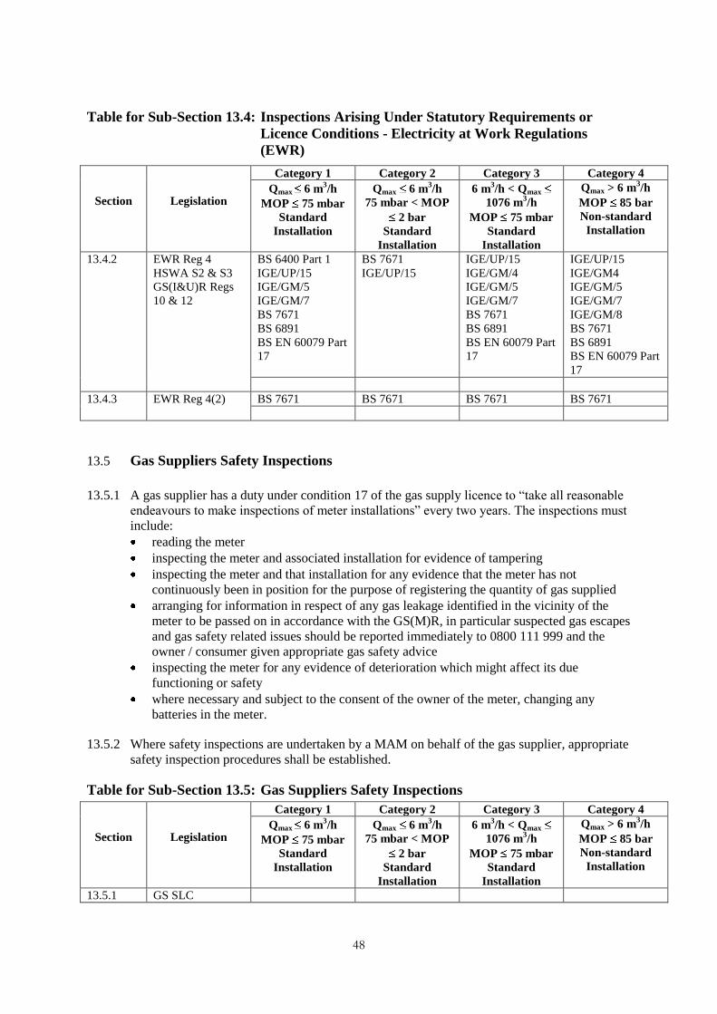
48
Table for Sub-Section 13.4: Inspections Arising Under Statutory Requirements or
Licence Conditions - Electricity at Work Regulations
(EWR)
Section
Legislation
Category 1 Category 2 Category 3 Category 4
Qmax 6 m3/h
MOP 75 mbar
Standard
Installation
Qmax 6 m3/h
75 mbar < MOP
2 bar
Standard
Installation
6 m3/h < Qmax
1076 m3/h
MOP 75 mbar
Standard
Installation
Qmax > 6 m3/h
MOP 85 bar
Non-standard
Installation
13.4.2 EWR Reg 4
HSWA S2 & S3
GS(I&U)R Regs
10 & 12
BS 6400 Part 1
IGE/UP/15
IGE/GM/5
IGE/GM/7
BS 7671
BS 6891
BS EN 60079 Part
17
BS 7671
IGE/UP/15
IGE/UP/15
IGE/GM/4
IGE/GM/5
IGE/GM/7
BS 7671
BS 6891
BS EN 60079 Part
17
IGE/UP/15
IGE/GM4
IGE/GM/5
IGE/GM/7
IGE/GM/8
BS 7671
BS 6891
BS EN 60079 Part
17
13.4.3 EWR Reg 4(2) BS 7671 BS 7671 BS 7671 BS 7671
13.5 Gas Suppliers Safety Inspections
13.5.1 A gas supplier has a duty under condition 17 of the gas supply licence to “take all reasonable
endeavours to make inspections of meter installations” every two years. The inspections must
include:
reading the meter
inspecting the meter and associated installation for evidence of tampering
inspecting the meter and that installation for any evidence that the meter has not
continuously been in position for the purpose of registering the quantity of gas supplied
arranging for information in respect of any gas leakage identified in the vicinity of the
meter to be passed on in accordance with the GS(M)R, in particular suspected gas escapes
and gas safety related issues should be reported immediately to 0800 111 999 and the
owner / consumer given appropriate gas safety advice
inspecting the meter for any evidence of deterioration which might affect its due
functioning or safety
where necessary and subject to the consent of the owner of the meter, changing any
batteries in the meter.
13.5.2 Where safety inspections are undertaken by a MAM on behalf of the gas supplier, appropriate
safety inspection procedures shall be established.
Table for Sub-Section 13.5: Gas Suppliers Safety Inspections
Section
Legislation
Category 1 Category 2 Category 3 Category 4
Qmax 6 m3/h
MOP 75 mbar
Standard
Installation
Qmax 6 m3/h
75 mbar < MOP
2 bar
Standard
Installation
6 m3/h < Qmax
1076 m3/h
MOP 75 mbar
Standard
Installation
Qmax > 6 m3/h
MOP 85 bar
Non-standard
Installation
13.5.1 GS SLC

49
14 Duty of Care beyond Asset
14.1 It shall be ensured that the MAM‟s meter installations do not cause a safety hazard to the
public during the life cycle of the installation.
14.2 A MAM shall determine if the works that they carry out, including tightness testing and
purging, will mean that the checks contained in Regulation 26 (9) of the GS(I&U)R need to
be carried out. Where it is determined that these checks are not necessary there is still a duty
of care on the MAM to verify that any connected appliances are working correctly when they
are re-lit following purging operations by that MAM.
14.3 A MAM must have procedures in place for reporting any dangerous occurrences as required
by the Reporting of Injuries, Diseases and Dangerous Occurrences Regulations 1995
(RIDDOR). There are requirements on CORGI registered gas installers to report to HSE
when they become aware of a gas fitting which is dangerous because of its design,
construction, manner of installation, modification or servicing.
14.4 A MAM must have procedures in place for advising the consumer, occupier or landlord
where a gas appliance cannot be used without danger, as required by GS(IU)R Reg 34(3).
Any person carrying out any work in relation to a gas main, service pipe or gas fitting who
becomes aware of an unsafe or dangerous appliance during the course of that work, has a duty
to inform the responsible person, whether or not the work is being carried out on that
appliance. However, this duty only extends to those issues which are within the competence
of the person engaged in work and which it is reasonable to expect the person to notice
through visual inspection, for example, when relighting an appliance following the
interruption of the gas supply or when observing an appliance in the course of other work. It
is not expected that additional tests and examinations should be undertaken on appliances not
being worked on by that person. Further information is given in industry guidance on 'unsafe
situations' procedures, for example as issued by CORGI.
50
15 Duty of Co-operation
15.1 GS(M)R places duties on parties involved in the supply of gas to premises to cooperate with
the relevant GT.
15.2 The MAM shall ensure that procedures are in place to provide information and, as
appropriate, services to other parties involved with the safe and secure supply of gas to
premises. These shall include but not be limited to:
ensuring that the Emergency Service Provider (ESP) is aware of how to isolate the
MAM‟s installations by provision of a line diagram- left at the installation
changes in fittings, technologies and methods of isolation that may impact on the ability
of the ESP to make safe shall be notified by providing an updated drawing- left at the
installation
sharing safety-related information with the appropriate parties (for example safety-related
defects with meters, meter regulators and installation fittings and components)
sharing information on faults or meter performance with the appropriate parties (for
example EnergyWatch, Ofgem)
sharing information on identified methods of theft of gas with other MAMs and the
relevant parties
informing appropriate parties of any procedure or equipment required to reinstate a gas
supply following interruption
liaising with the GT or ESP on instances of over or under pressurisation, gas escapes,
water ingress, loss of supply etc.
co-operating with the meter reading agencies.
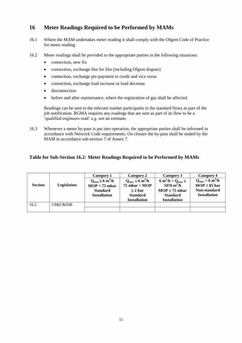
51
16 Meter Readings Required to be Performed by MAMs
16.1 Where the MAM undertakes meter reading it shall comply with the Ofgem Code of Practice
for meter reading.
16.2 Meter readings shall be provided to the appropriate parties in the following situations:
connection, new fix
connection, exchange like for like (including Ofgem dispute)
connection, exchange pre-payment to credit and vice versa
connection, exchange load increase or load decrease
disconnection
before and after maintenance, where the registration of gas shall be affected.
Readings can be sent to the relevant market participants in the standard flows as part of the
job notification. RGMA requires any readings that are sent as part of its flow to be a
„qualified engineers read‟ e.g. not an estimate.
16.3 Whenever a meter by-pass is put into operation, the appropriate parties shall be informed in
accordance with Network Code requirements. On closure the by-pass shall be sealed by the
MAM in accordance sub-section 7 of Annex 7.
Table for Sub-Section 16.2: Meter Readings Required to be Performed by MAMs
Section
Legislation
Category 1 Category 2 Category 3 Category 4
Qmax 6 m3/h
MOP 75 mbar
Standard
Installation
Qmax 6 m3/h
75 mbar < MOP
2 bar
Standard
Installation
6 m3/h < Qmax
1076 m3/h
MOP 75 mbar
Standard
Installation
Qmax > 6 m3/h
MOP 85 bar
Non-standard
Installation
16.2 GM(C&D)R

52
17 Installation Performance and Functionality Monitoring
17.1 General
Performance and functionality monitoring is the process of verifying that a meter installation
is operating as intended.
17.2 Specific
The requirements of this section cover the policies, procedures and processes for monitoring
meter installation performance and functionality.
17.2.1 A policy for monitoring the performance and functionality of meters and meter installation
components shall be established with the gas supplier. The information obtained from the
monitoring should be used to determine the asset replacement policy.
17.2.2 Where a type of component is recalled, the type exchange policy to be adopted shall be
established with the gas supplier.
17.2.3 Where a type of component is recalled for reasons of safety, a risk assessment shall be
undertaken to establish the type exchange policy to be adopted.
Table for Sub-Section 17.2: Installation Performance and Functionality Monitoring –
Specific
Section
Legislation
Category 1 Category 2 Category 3 Category 4
Qmax 6 m3/h
MOP 75 mbar
Standard
Installation
Qmax 6 m3/h
75 mbar < MOP
2 bar
Standard
Installation
6 m3/h < Qmax
1076 m3/h
MOP 75 mbar
Standard
Installation
Qmax > 6 m3/h
MOP 85 bar
Non-standard
Installation
17.2.1 IGE/TD/15
Ofgas COP1/c
17.3 General Commercial Dispute
17.3.1 In the event that a consumer disputes the accuracy of the meter installation, or some other
aspect of its functionality, it shall be determined whether the installation is functioning
correctly, and it shall be demonstrated to the consumer accordingly.
Note: This may entail demonstrating that the problem lies either with the gas consumer’s own plant or the supply
network.
17.3.2 If the meter installation is found to be not functioning correctly, the fault or faults shall be
rectified where they lie within the meter installation.

53
17.3.3 In the event that the meter installation functionality is being adversely affected by the
consumer‟s own plant, advice shall be given to the consumer on the appropriate standards that
the plant should be installed to.
17.3.4 In the event that an amicable agreement cannot be reached concerning an accuracy dispute on
a stamped meter, the consumer has the right to insist on an Ofgem disputed meter test.
17.4 Disputed Meter Testing
On receiving a request for an Ofgem disputed meter test, the MAM shall follow the Ofgem
procedure for the removal of meters. The meter shall be removed in accordance with Section
19.
Table for Sub-Section 17.4: Installation Performance and Functionality Monitoring -
Disputed Meter Testing
Section
Legislation
Category 1 Category 2 Category 3 Category 4
Qmax 6 m3/h
MOP 75 mbar
Standard
Installation
Qmax 6 m3/h
75 mbar < MOP
2 bar
Standard
Installation
6 m3/h < Qmax
1076 m3/h
MOP 75 mbar
Standard
Installation
Qmax > 6 m3/h
MOP 85 bar
Non-standard
Installation
17.4 Gas Act schedule
2B section 6
GMR as amended
17.5 Verification of Meter Accuracy
17.5.1 Meters shall be maintained in proper working order for registering the quantity of gas
supplied. This can be achieved by an appropriate maintenance regime described in Section 12
or by the procedure in sub-section 17.5.2.
Note: In addition to the requirements of the MAMCoP, there may be additional contractual requirements.
17.5.2 Procedure for Sample Testing
If sampling is employed, it shall be undertaken periodically by manufacturer, meter
designation, badged capacity and year. Sample sizes shall be statistically robust with
respect to determining the in-service accuracy requirements determined by legislation or
best industry practice.
Appropriate testing of meters shall be carried out using test equipment calibrated to
nationally traceable standards and recommended test procedures. Records of results of the
sampling exercise shall be maintained such that the requirements to maintain meters in
proper working order for registering the quantity of gas supplied can be evidenced to
interested parties (for example Ofgem, meter manufacturers).

54
Table for Sub-Section 17.5: Installation Performance and Functionality Monitoring -
Procedure for Sample Testing
Section
Legislation
Category 1 Category 2 Category 3 Category 4
Qmax 6 m3/h
MOP 75 mbar
Standard
Installation
Qmax 6 m3/h
75 mbar < MOP
2 bar
Standard
Installation
6 m3/h < Qmax
1076 m3/h
MOP 75 mbar
Standard
Installation
Qmax > 6 m3/h
MOP 85 bar
Non-standard
Installation
17.5 Gas Act schedule
2B section 2 (1) b
55
18 Cessation of Gas Supply
18.1 General
The supply of gas at a meter installation may cease under the terms of the GT Network Code
or under Schedule 2B of the Gas Act 1986 as amended 1995. The terms under which a
supply of gas or gas may cease are:
Discontinuance – An act by a gas supplier as a means of stopping the flow of gas at a gas
supply meter point.
Disconnection – An act by a GT to ensure that gas cannot be off-taken through a supply
meter point.
18.2 Specific
The requirements of this section cover all actions required at the meter installation at
cessation of a gas supply.
18.2.1 Where a MAM undertakes the discontinuance of a gas supply on behalf of a gas supplier then
the following requirements apply:
(a) The work shall be undertaken by a competent person having the ability, appropriate
training, knowledge and experience to undertake the work.
(b) The discontinuance shall be made using safe operating practices in accordance with
18.2.2(below).
18.2.2 Procedures shall be put in place to undertake the discontinuance in a safe and secure manner
and shall take into account any requirement for the purging of the meter installation and the
downstream installation pipework. Where purging of the downstream pipework is required,
the meter shall not be removed until purging has been carried out or is in progress.
18.2.3 Where a meter is removed as part of a discontinuance the gas service shall be labelled with a
warning notice to indicate the presence of gas, the serial number of the meter that has been
removed, the date of removal and the final meter reading.
18.2.4 The gas supplier shall be notified once the discontinuance has been carried out. The
requirements of the GM(C&D)R (Annex 5) must be met.
18.2.5 Where a GT carries out a disconnection and subsequently notifies the MAM (thro‟ the gas
supplier), the MAM shall make commercial arrangements for the future actions covering the
redundant meter installation, such as removal from site.
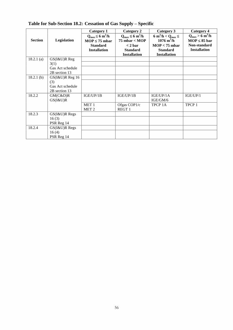
56
Table for Sub-Section 18.2: Cessation of Gas Supply – Specific
Section
Legislation
Category 1 Category 2 Category 3 Category 4
Qmax 6 m3/h
MOP 75 mbar
Standard
Installation
Qmax 6 m3/h
75 mbar < MOP
2 bar
Standard
Installation
6 m3/h < Qmax
1076 m3/h
MOP 75 mbar
Standard
Installation
Qmax > 6 m3/h
MOP 85 bar
Non-standard
Installation
18.2.1 (a) GS(I&U)R Reg
3(1)
Gas Act schedule
2B section 13
18.2.1 (b) GS(I&U)R Reg 16
(3)
Gas Act schedule
2B section 13
18.2.2 GM(C&D)R
GS(I&U)R
IGE/UP/1B IGE/UP/1B IGE/UP/1A
IGE/GM/6
IGE/UP/1
MET 1
MET 2
Ofgas COP1/c
REGT 1
TPCP 1A TPCP 1
18.2.3 GS(I&U)R Regs
16 (3)
PSR Reg 14
18.2.4 GS(I&U)R Regs
16 (4)
PSR Reg 14

57
19 Removal and Return of Meters and Installation Kit
19.1 General
Meter removal is the process by which a meter or meter installation is removed in a safe
manner and which leaves the remaining parts of the installation or any other pipework in a
safe condition.
Table for Sub-Section 19.1: Removal and Return of Meters and Installation Kit –
General
Section
Legislation
Category 1 Category 2 Category 3 Category 4
Qmax 6 m3/h
MOP 75 mbar
Standard
Installation
Qmax 6 m3/h
75 mbar < MOP
2 bar
Standard
Installation
6 m3/h < Qmax
1076 m3/h
MOP 75 mbar
Standard
Installation
Qmax > 6 m3/h
MOP 85 bar
Non-standard
Installation
19.1 GS(I&U)R Reg 16
(3)
BS 6400 Part 1
IGE/UP/1B
BS6 400 Part 2
IGE/UP/1B
IGE/UP/1A
IGE/GM/6
IGE/UP/1
MET 1
MET 2
Ofgas COP1/c
REGT 1
TPCP 1A TPCP 1
19.2 Specific
The requirements of this section cover the removal of the meter or the complete installation.
19.2.1 Prior to any removal work being carried out, it shall be verified that the meter to be removed
is the correct meter. This should involve ensuring that the meter records for the meter point
match the details of the meter on site.
19.2.2 If meter removal is associated with demolition the requirements of CDMR for notifications,
method statements etc. must be met.
19.2.3 A temporary continuity bond, using appropriately sized earthing cable, should be fitted across
the meter or pipework that is to be removed. This bond shall remain in place until the work is
completed. If the two pipe ends are in the same room or space they shall be electrically
bonded and consideration should be given to other pipework within the meter house with
which electrical continuity should be maintained.
19.2.4 When removing a meter, care shall be taken to ensure that the meter is not damaged so that it
can be tested in the event of a dispute and, where appropriate, be recycled or refurbished. For
meters which are the subject of an accuracy dispute, reference should be made to section
19.2.6 and 19.2.11 below.
19.2.5 Where appropriate, removed meters shall be purged prior to capping or sealing the inlet and
outlet connections, to prevent the ingress of air, dirt or moisture.
19.2.6 Prior to disposal, the meter shall be decommissioned and any fitted batteries removed.
Removed batteries must be disposed of in accordance with current environmental legislation.
19.2.7 For a meter that is the subject of an accuracy dispute any liquid, such as water, present in the
measuring chamber shall not be drained, and the meter connections securely capped. Where

58
appropriate, any oil present in the meter for lubrication purposes shall be drained and should
accompany the meter. The MAM shall make arrangements for any necessary special
equipment for transporting such meters.
19.2.8 Where appropriate, any liquid present in any other removed meters shall be drained and
disposed of in accordance with current environmental legislation.
19.2.9 Any removed meter shall be stored and transported in the same orientation as it was when
installed and used.
19.2.10 Where appropriate, outlet pipework shall be purged in accordance with IGE/UP/1,
IGE/UP/1A or IGE/UP/1B, or other IGEM recommendations.
19.2.11 Any open ends of pipework (including the ECV) left by the removal of a meter shall be sealed
with an appropriate fitting. The gas supplier must be informed if the meter is not immediately
replaced; in turn the suppler must notify the GT so that they can close any service valve
controlling the supply of gas to that meter if that valve does not supply other meters.
19.2.12 Removed meters and installation kits shall be held in secure, weatherproof storage by the
incoming MAM pending instructions from the outgoing meter owner. Information such as
whereabouts of the meter and its availability for collection shall be provided within one
month of meter removal. Where the outgoing meter owner is not known and cannot be
ascertained, contact shall be made with the relevant GT who may be able to supply this
information. MAMs shall make suitable commercial arrangements between themselves for
the collection, return and disposal of removed meters and installation kits – this should occur
within one month of notification.
19.2.13 For a meter that is the subject of an accuracy dispute, the meter shall be handled with extreme
care in order that it arrives at the test station in the same condition as when it was
disconnected, complete with any batteries fitted, the exception being electronic token meters
employing a battery whose removal will not affect the metrological performance of the meter.

59
Table for Sub-Section 19.2: Removal and Return of Meters and Installation Kit -
Specific
Section
Legislation
Category 1 Category 2 Category 3 Category 4
Qmax 6 m3/h
MOP 75 mbar
Standard
Installation
Qmax 6 m3/h
75 mbar < MOP
2 bar
Standard
Installation
6 m3/h < Qmax
1076 m3/h
MOP 75 mbar
Standard
Installation
Qmax > 6 m3/h
MOP 85 bar
Non-standard
Installation
19.2.2 CDMR
19.2.3 GS(I&U)R Reg 10 BS 6400 Part 1 BS 6400 Part 2, when published. In the interim use IGE/TD/15
IGE/GM/6
MET 1
MET 2
MET 3LS
MET 1
MET 2
MET 3LS
REGT 1
MET 4
CMET 1
CMET 1
CMET 2
19.2.6 COSHH
19.2.10 GS(I&U)R Regs
6, 22
IGE/UP/1B IGE/UP/1B IGE/UP/1
IGE/UP/1A
IGE/GM/8
IGE/GM/4
IGE/UP/1
MET 1
MET 2
MET 3LS
Ofgas COP1/c
REGT 1
MET 4
CMET 1
TCPC 1
TCPC 1A
CMET 1
CMET 2
TCPC 1
19.2.11 GS(I&U)R Regs
6, 16 (3), 22
BS 6400 Part 1 BS 6400 Part 2, when published. In the interim use IGE/TD/15
IGE/GM/6
MET 1
MET 2
MET 3LS
Ofgas COP1/c
REGT 1
MET 4
CMET 1
CMET 2
19.2.12 GS SLC
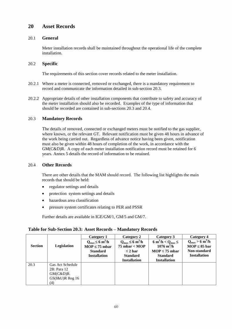
60
20 Asset Records
20.1 General
Meter installation records shall be maintained throughout the operational life of the complete
installation.
20.2 Specific
The requirements of this section cover records related to the meter installation.
20.2.1 Where a meter is connected, removed or exchanged, there is a mandatory requirement to
record and communicate the information detailed in sub-section 20.3.
20.2.2 Appropriate details of other installation components that contribute to safety and accuracy of
the meter installation should also be recorded. Examples of the type of information that
should be recorded are contained in sub-sections 20.3 and 20.4.
20.3 Mandatory Records
The details of removed, connected or exchanged meters must be notified to the gas supplier,
where known, or the relevant GT. Relevant notification must be given 48 hours in advance of
the work being carried out. Regardless of advance notice having been given, notification
must also be given within 48 hours of completion of the work, in accordance with the
GM(C&D)R. A copy of each meter installation notification record must be retained for 6
years. Annex 5 details the record of information to be retained.
20.4 Other Records
There are other details that the MAM should record. The following list highlights the main
records that should be held:
regulator settings and details
protection system settings and details
hazardous area classification
pressure system certificates relating to PER and PSSR
Further details are available in IGE/GM/1, GM/5 and GM/7.
Table for Sub-Section 20.3: Asset Records – Mandatory Records
Section
Legislation
Category 1 Category 2 Category 3 Category 4
Qmax 6 m3/h
MOP 75 mbar
Standard
Installation
Qmax 6 m3/h
75 mbar < MOP
2 bar
Standard
Installation
6 m3/h < Qmax
1076 m3/h
MOP 75 mbar
Standard
Installation
Qmax > 6 m3/h
MOP 85 bar
Non-standard
Installation
20.3 Gas Act Schedule
2B: Para 12
GM(C&D)R.
GS(I&U)R Reg 16
(4)

61
21 Asset Transfer from MAM to MAM (Guidance only)
21.1 General
The seamless transfer of assets will be a factor of the competitive environment related to
meter installations. Flow of accurate and relevant information will facilitate the process.
21.2 Specific
The requirements of this section cover the disclosure of relevant information on transfer of an
asset between meter asset managers. Where agreement has been reached on the transfer of
metering assets details of the transferred asset shall be provided in accordance with 21.2.1
below.
21.2.1 The following information should be recorded where appropriate, and relevant information
sent to interested market participants (see RGMA Processes and Data for industry standard
flows):
meter address
meter type (for example, diaphragm)
manufacturer
year of manufacturer
meter model (for example G4)
meter serial number or meter module number
maximum stamped (badged) capacity
number of dials or drums for billing purposes
index scaling (for example x1, x10, x100)
registration units (for example m3)
payment type (for example credit or pre-payment)
meter index reading
metering pressure
meter height above sea level
meter location in the premises
whether a by-pass is fitted
whether the by-pass is sealed
whether a security collar is fitted
converter details
pressure test certificates
hazardous area classification
DSEAR certificates
warrantee details
regulator and protection system details
details of diagnostic flags
maintenance history
safety device settings.

62
22 Permanent Disposal
22.1 General
At the end of the operational life of a meter installation or any composite part appropriate
disposal is necessary to complete the cycle of whole life management.
22.2 Specific
This section covers guidance on the measures to be taken when permanently disposing of
(scrapping) meters and other installation equipment. In addition to the requirements of this
MAMCoP there are RGMA data requirements which relate to removing metering assets.
These include notifying the Gas Act Owner and/or MAM of the removal and collection
details.
22.3 Specific Requirements
Care should be taken to consider environmental impact when disposing of meters. In
particular the following factors apply:
where possible, all components of the meter should be reused or recycled, provided this
does not involve excessive cost
where appropriate the meter shall be purged prior to scrapping
all meter batteries must be removed and disposed of in accordance with current
environmental and waste disposal legislation
any oil should be drained from the meter and must be disposed of in accordance with
current environmental and waste disposal legislation
meter components containing or likely to contain mercury or other hazardous chemicals
must be removed from the meter prior to the disposal and then disposed of in accordance
with current environmental and waste disposal legislation. Alternatively the meter as a
whole must be sent to a suitably equipped and competent facility capable of disposing of
the meter in accordance with current environmental and waste disposal legislation
when scrapping a meter, official seals shall be permanently defaced, and the meter shall
be rendered inoperable, (for example diaphragm meters can be spiked, the index on RPD
and turbine meters can be destroyed, and/or the measuring element irreparably damaged)
a record of all meters permanently disposed of shall be maintained for a minimum period
of 3 years.

63
Annex 1: Correlation with OAMI Codes of Practice
Clause title CoP 1/a CoP 1/b CoP 1/c MAMCoP
CORGI Registration 4.1 4.1 (same as a) 4.1 (same as a) 3.4
Safety and integrity of the system - - 4.2 6
Responsible engineer - - 4.3 7.2.3
Competency of Employees 4.2 4.2 (same as a) 4.4 3.4
Sub-contract 4.3 4.3 (same as a) 4.5 3.4
Installation regulations and
standards
4.4 4.4 7.4.1
Gas supply requirements 4.5 4.5 4.6 4.2
Meter type 4.6 - - 5.2.1
Installation design and meter
selection
- 4.6 4.7 5.2
gas flow variations - - 4.7a 5.2.1
large loads at elevated
pressures
- - 4.7b 4.2.4, 5.2.1,
5.2.4
pigging facilities - - 4.7c 4.2.13
Inclusion of a by-pass - - 4.8 4.2.16
Seals on Approved meters 4.7 4.7 (same as a) - 5.2.2
Use of stamped meters - - 4.9 5.2.2
Location of meter installation 4.8 4.8 4.10 4.2.11, 5.2.7
Installation materials 4.9 4.9 4.11 5.2.5
PGT installation approval and
notification
4.10 4.11 4.13 6.2, 6.3
Additional installation skills - 4.10 7.4.1
Commissioning 4.11 4.12 4.14 9
Control and care of meters 4.12 4.13 (same as a) 4.15 (same as a) 19
meter removal 4.12a 4.13a (same as a) 4.15a 19
transportation, handling and
storage of meters
4.12b 4.13b (same as a) 4.15b (same as a) 19
disposal of meters 4.12c 4.13c (same as a) 4.15c (same as a) 22
Maintenance of meter installations 4.13 4.14 (same as a) 4.16 (same as a) 12
Meter replacement 4.14 4.15 4.17 8.2, 8.3, 17.3
Notification of meter details 4.15 4.16 (same as a) 4.18 (same as a) 10
confidentiality 4.16 4.17 (same as a) 4.19 (same as a) Annex 2, 3I
consumer details 4.16a 4.17a (same as a) 4.19 (same as a) Annex 2, 3(c)
commercial information 4.16b 4.17b (same as a) 4.19 (same as a) 10.6
Audit 4.17 4.18 (same as a) 4.20 (same as a) 3.1, 7.4.2

64
Annex 2: Example of a Code of Conduct
The following is an example of General Rules of Conduct for all employees of the MAM employed
on meter work:
1 Safety and Security
You shall:
(a) observe all gas and other safety regulations, statutes and authorised Codes of Practice
(b) not act in a manner likely to endanger yourself or any other person (including
members of the public) or property
(c) not smoke in any area designated as a 'No Smoking' zone, where safety or a special
health hazard might exist, for example 'Live Gas Working'
(d) co-operate with security and safety measures prescribed to protect life and property,
using safety equipment where appropriate.
2 General Conduct and Performance at Work
You shall:
(a) ensure when on duty that drink or drugs do not affect your performance
(b) not smoke whilst on a consumer‟s premises
(c) not act in an abusive, violent or irresponsible manner towards persons or property
(d) not discriminate against consumers on any grounds for example sex, colour, race,
creed, nationality or ethnic origin
(e) obey reasonable instructions and follow laid down working procedures
(f) act in a manner, which will maintain satisfactory relations with consumers and
members of the public, avoiding unwelcome physical advances, suggestive remarks,
language or transmit comments likely to cause distress or offence.
(g) carry out work in a careful, attentive and competent manner, to the required
standards.
(h) avoid bringing the gas industry into disrepute or in any way hindering the efficiency
of its operation.
3 Theft, Fraud, Personal Gain and Disclosure of Confidential Information
You shall not:
(a) misappropriate property;
(b) divert business to a competitor
(c) or reveal confidential information to an unauthorised party
4 Miscellaneous
You shall:
(a) wear such uniform or protective clothing as is provided
(b) produce an identity card when required, and wear it in such a manner that it can be
seen at all times
(c) dress in a presentable manner suited to your job and the circumstances in which it is
performed.

65
5 If in Doubt
This Code has been prepared to give guidance. If you are ever in doubt about any matter
concerning conduct or any other issue regarding your work, you should seek advice from your
manager.

66
Annex 3: Legislative References and Technical Publications
1 Legislative References
Acronym Full Name
ATEX 137 Explosive Atmospheres Directive (99/92/EC)
ATEX 95 Explosive Atmospheres Directive (94/9/EC)
CAD Chemical Agents Directive (98/24/EC)
CDMR Construction (Design and Management) Regulations 1994
COSHH Control of Substances Hazardous to Health Regulations 2002
CPD Construction Products Directive - Construction (Design and Management)
Regulations 1997
DSEAR Dangerous Substances and Explosive Atmospheres Regulations 2002
EPS Equipment and Protective Systems for Use in Potentially Explosive
Atmospheres Regulations 1996 (As Amended)
EWR Electricity at Work Regulations 1989
GA Gas Act 1986, and where relevant as amended by Gas Act 1995
GM(C&D)R Gas Meters (Information on Connection and Disconnection) Regulations
1996
GMR Gas Meter Regulations (and Amendments) 1983
GS(I&U)R Gas Safety (Installation and Use) Regulations 1998
GS(M)R Gas Safety (Management) Regulations 1996
GT SLC Gas Transporters' Standard Licence Condition 2001
GS SLC Gas Suppliers' Standard Licence Condition 2001
GTER Gas (Calculation of Thermal Energy) Regulations 1996
HSWA Health & Safety at Work Act 1974
LOLER Lifting Operations and Lifting Equipment Regulations 1998
MID European Measuring Instruments Directive (2004/22/EC)
MHOR Manual Handling Operations Regulations 1992
MHSWR Management Health & Safety at Work Regulations 1999
NRSWA New Roads and Street Works Act 1991
NWR The Noise at Work Regulations 1989
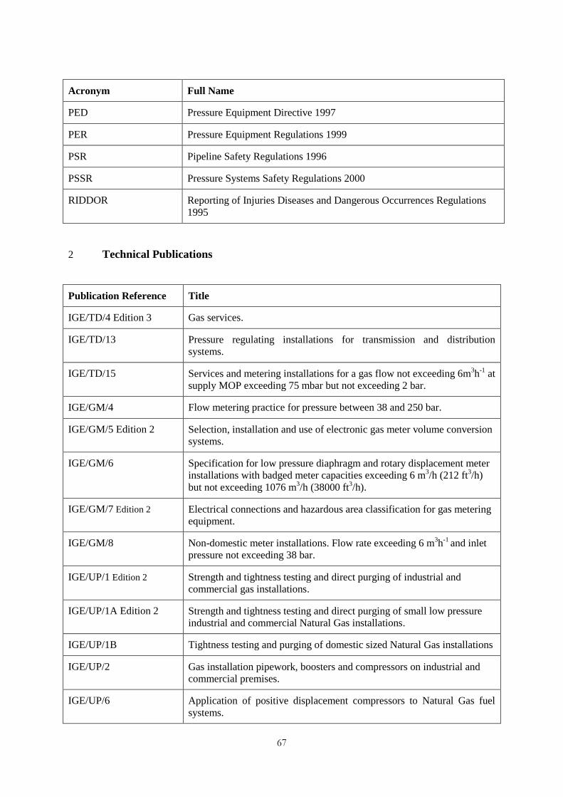
67
Acronym Full Name
PED Pressure Equipment Directive 1997
PER Pressure Equipment Regulations 1999
PSR Pipeline Safety Regulations 1996
PSSR Pressure Systems Safety Regulations 2000
RIDDOR Reporting of Injuries Diseases and Dangerous Occurrences Regulations
1995
2 Technical Publications
Publication Reference Title
IGE/TD/4 Edition 3 Gas services.
IGE/TD/13 Pressure regulating installations for transmission and distribution
systems.
IGE/TD/15 Services and metering installations for a gas flow not exceeding 6m3h
-1 at
supply MOP exceeding 75 mbar but not exceeding 2 bar.
IGE/GM/4 Flow metering practice for pressure between 38 and 250 bar.
IGE/GM/5 Edition 2 Selection, installation and use of electronic gas meter volume conversion
systems.
IGE/GM/6 Specification for low pressure diaphragm and rotary displacement meter
installations with badged meter capacities exceeding 6 m3/h (212 ft
3/h)
but not exceeding 1076 m3/h (38000 ft
3/h).
IGE/GM/7 Edition 2 Electrical connections and hazardous area classification for gas metering
equipment.
IGE/GM/8 Non-domestic meter installations. Flow rate exceeding 6 m3h
-1 and inlet
pressure not exceeding 38 bar.
IGE/UP/1 Edition 2 Strength and tightness testing and direct purging of industrial and
commercial gas installations.
IGE/UP/1A Edition 2 Strength and tightness testing and direct purging of small low pressure
industrial and commercial Natural Gas installations.
IGE/UP/1B Tightness testing and purging of domestic sized Natural Gas installations
IGE/UP/2 Gas installation pipework, boosters and compressors on industrial and
commercial premises.
IGE/UP/6 Application of positive displacement compressors to Natural Gas fuel
systems.
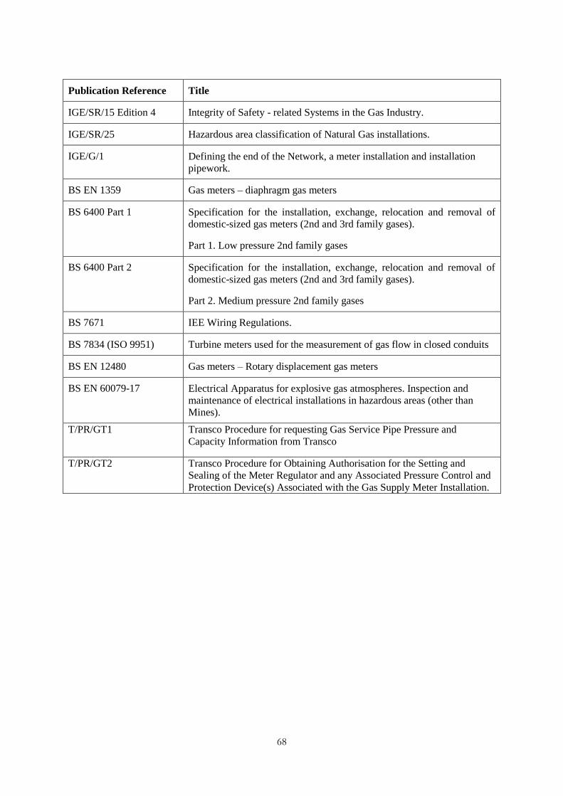
68
Publication Reference Title
IGE/SR/15 Edition 4 Integrity of Safety - related Systems in the Gas Industry.
IGE/SR/25 Hazardous area classification of Natural Gas installations.
IGE/G/1 Defining the end of the Network, a meter installation and installation
pipework.
BS EN 1359 Gas meters – diaphragm gas meters
BS 6400 Part 1 Specification for the installation, exchange, relocation and removal of
domestic-sized gas meters (2nd and 3rd family gases).
Part 1. Low pressure 2nd family gases
BS 6400 Part 2 Specification for the installation, exchange, relocation and removal of
domestic-sized gas meters (2nd and 3rd family gases).
Part 2. Medium pressure 2nd family gases
BS 7671 IEE Wiring Regulations.
BS 7834 (ISO 9951) Turbine meters used for the measurement of gas flow in closed conduits
BS EN 12480 Gas meters – Rotary displacement gas meters
BS EN 60079-17 Electrical Apparatus for explosive gas atmospheres. Inspection and
maintenance of electrical installations in hazardous areas (other than
Mines).
T/PR/GT1
Transco Procedure for requesting Gas Service Pipe Pressure and
Capacity Information from Transco
T/PR/GT2
Transco Procedure for Obtaining Authorisation for the Setting and
Sealing of the Meter Regulator and any Associated Pressure Control and
Protection Device(s) Associated with the Gas Supply Meter Installation.
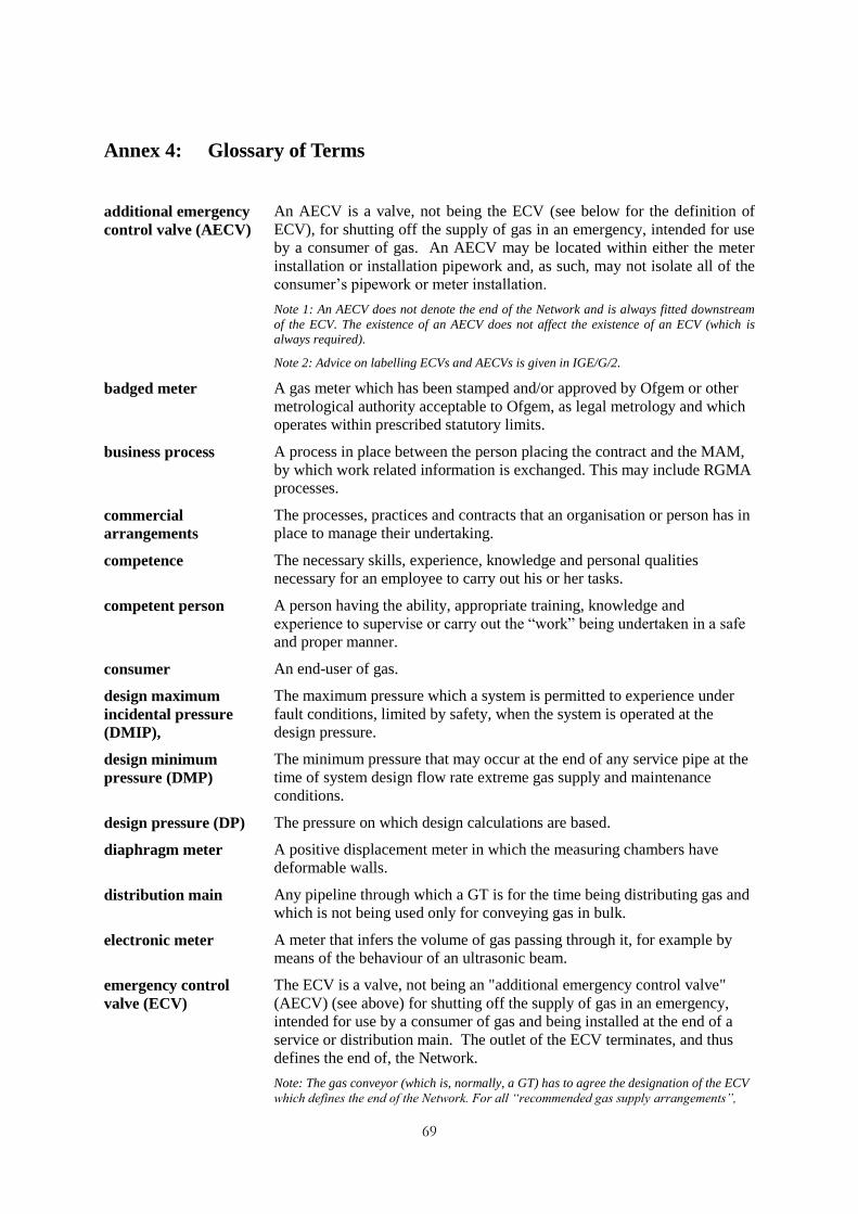
69
Annex 4: Glossary of Terms
additional emergency
control valve (AECV)
An AECV is a valve, not being the ECV (see below for the definition of
ECV), for shutting off the supply of gas in an emergency, intended for use
by a consumer of gas. An AECV may be located within either the meter
installation or installation pipework and, as such, may not isolate all of the
consumer‟s pipework or meter installation.
Note 1: An AECV does not denote the end of the Network and is always fitted downstream
of the ECV. The existence of an AECV does not affect the existence of an ECV (which is
always required).
Note 2: Advice on labelling ECVs and AECVs is given in IGE/G/2.
badged meter A gas meter which has been stamped and/or approved by Ofgem or other
metrological authority acceptable to Ofgem, as legal metrology and which
operates within prescribed statutory limits.
business process A process in place between the person placing the contract and the MAM,
by which work related information is exchanged. This may include RGMA
processes.
commercial
arrangements
The processes, practices and contracts that an organisation or person has in
place to manage their undertaking.
competence The necessary skills, experience, knowledge and personal qualities
necessary for an employee to carry out his or her tasks.
competent person A person having the ability, appropriate training, knowledge and
experience to supervise or carry out the “work” being undertaken in a safe
and proper manner.
consumer An end-user of gas.
design maximum
incidental pressure
(DMIP),
The maximum pressure which a system is permitted to experience under
fault conditions, limited by safety, when the system is operated at the
design pressure.
design minimum
pressure (DMP)
The minimum pressure that may occur at the end of any service pipe at the
time of system design flow rate extreme gas supply and maintenance
conditions.
design pressure (DP) The pressure on which design calculations are based.
diaphragm meter A positive displacement meter in which the measuring chambers have
deformable walls.
distribution main Any pipeline through which a GT is for the time being distributing gas and
which is not being used only for conveying gas in bulk.
electronic meter A meter that infers the volume of gas passing through it, for example by
means of the behaviour of an ultrasonic beam.
emergency control
valve (ECV)
The ECV is a valve, not being an "additional emergency control valve"
(AECV) (see above) for shutting off the supply of gas in an emergency,
intended for use by a consumer of gas and being installed at the end of a
service or distribution main. The outlet of the ECV terminates, and thus
defines the end of, the Network.
Note: The gas conveyor (which is, normally, a GT) has to agree the designation of the ECV
which defines the end of the Network. For all “recommended gas supply arrangements”,
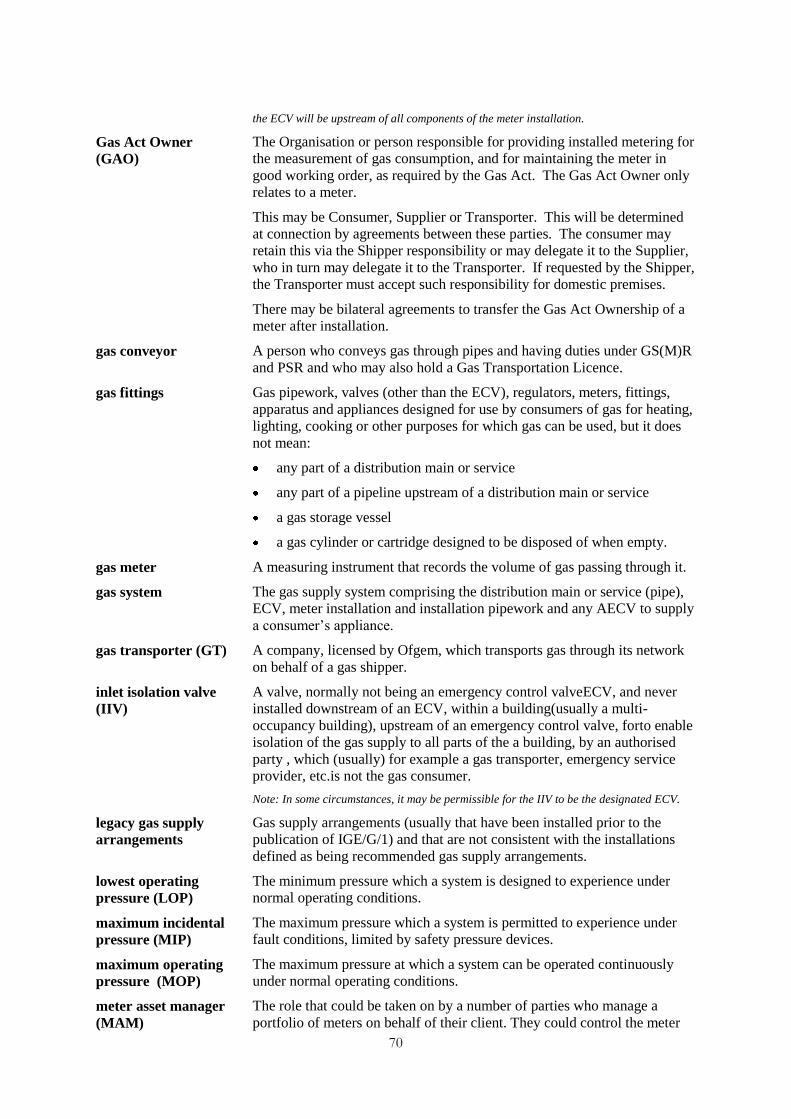
70
the ECV will be upstream of all components of the meter installation.
Gas Act Owner
(GAO)
The Organisation or person responsible for providing installed metering for
the measurement of gas consumption, and for maintaining the meter in
good working order, as required by the Gas Act. The Gas Act Owner only
relates to a meter.
This may be Consumer, Supplier or Transporter. This will be determined
at connection by agreements between these parties. The consumer may
retain this via the Shipper responsibility or may delegate it to the Supplier,
who in turn may delegate it to the Transporter. If requested by the Shipper,
the Transporter must accept such responsibility for domestic premises.
There may be bilateral agreements to transfer the Gas Act Ownership of a
meter after installation.
gas conveyor A person who conveys gas through pipes and having duties under GS(M)R
and PSR and who may also hold a Gas Transportation Licence.
gas fittings Gas pipework, valves (other than the ECV), regulators, meters, fittings,
apparatus and appliances designed for use by consumers of gas for heating,
lighting, cooking or other purposes for which gas can be used, but it does
not mean:
any part of a distribution main or service
any part of a pipeline upstream of a distribution main or service
a gas storage vessel
a gas cylinder or cartridge designed to be disposed of when empty.
gas meter A measuring instrument that records the volume of gas passing through it.
gas system The gas supply system comprising the distribution main or service (pipe),
ECV, meter installation and installation pipework and any AECV to supply
a consumer‟s appliance.
gas transporter (GT) A company, licensed by Ofgem, which transports gas through its network
on behalf of a gas shipper.
inlet isolation valve
(IIV)
A valve, normally not being an emergency control valveECV, and never
installed downstream of an ECV, within a building(usually a multi-
occupancy building), upstream of an emergency control valve, forto enable
isolation of the gas supply to all parts of the a building, by an authorised
party , which (usually) for example a gas transporter, emergency service
provider, etc.is not the gas consumer.
Note: In some circumstances, it may be permissible for the IIV to be the designated ECV.
legacy gas supply
arrangements
Gas supply arrangements (usually that have been installed prior to the
publication of IGE/G/1) and that are not consistent with the installations
defined as being recommended gas supply arrangements.
lowest operating
pressure (LOP)
The minimum pressure which a system is designed to experience under
normal operating conditions.
maximum incidental
pressure (MIP)
The maximum pressure which a system is permitted to experience under
fault conditions, limited by safety pressure devices.
maximum operating
pressure (MOP)
The maximum pressure at which a system can be operated continuously
under normal operating conditions.
meter asset manager
(MAM)
The role that could be taken on by a number of parties who manage a
portfolio of meters on behalf of their client. They could control the meter
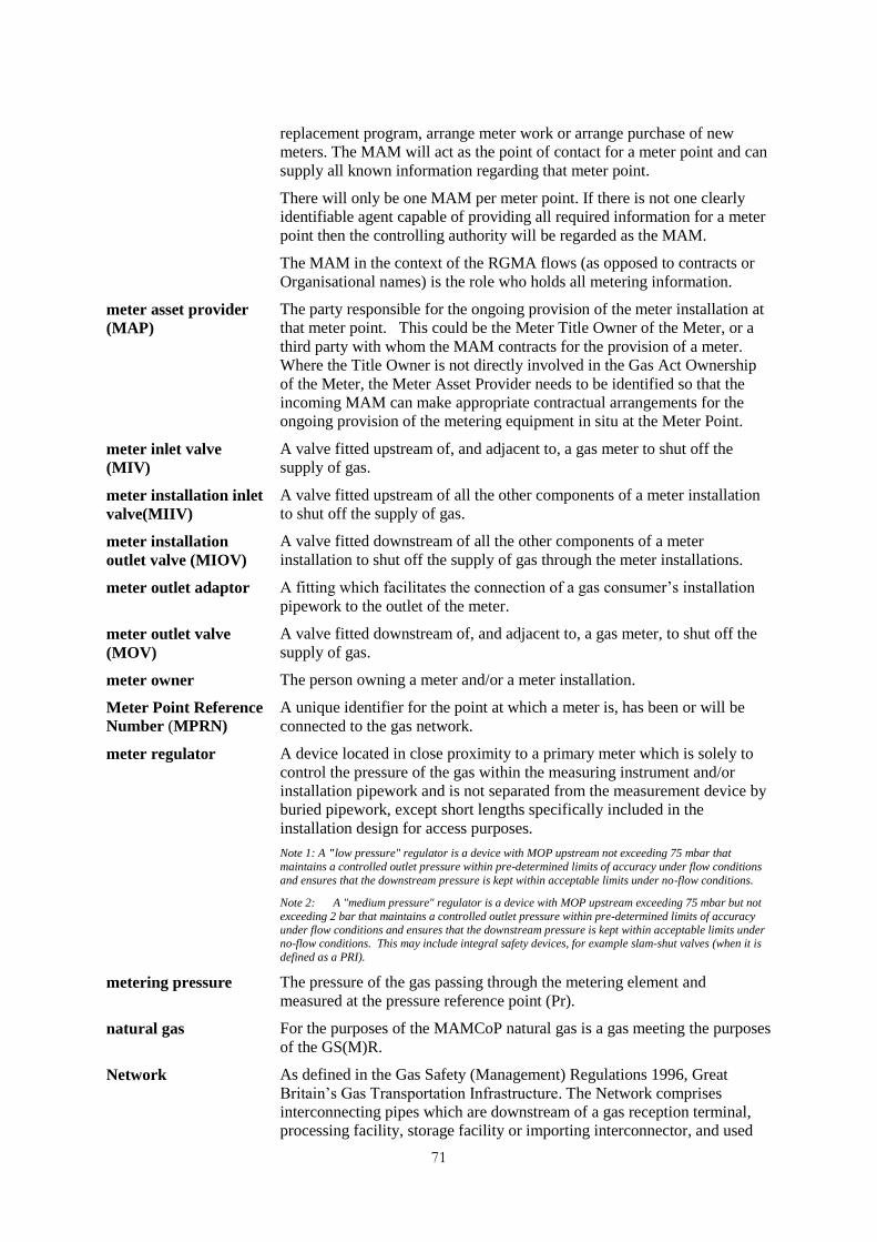
71
replacement program, arrange meter work or arrange purchase of new
meters. The MAM will act as the point of contact for a meter point and can
supply all known information regarding that meter point.
There will only be one MAM per meter point. If there is not one clearly
identifiable agent capable of providing all required information for a meter
point then the controlling authority will be regarded as the MAM.
The MAM in the context of the RGMA flows (as opposed to contracts or
Organisational names) is the role who holds all metering information.
meter asset provider
(MAP)
The party responsible for the ongoing provision of the meter installation at
that meter point. This could be the Meter Title Owner of the Meter, or a
third party with whom the MAM contracts for the provision of a meter.
Where the Title Owner is not directly involved in the Gas Act Ownership
of the Meter, the Meter Asset Provider needs to be identified so that the
incoming MAM can make appropriate contractual arrangements for the
ongoing provision of the metering equipment in situ at the Meter Point.
meter inlet valve
(MIV)
A valve fitted upstream of, and adjacent to, a gas meter to shut off the
supply of gas.
meter installation inlet
valve(MIIV)
A valve fitted upstream of all the other components of a meter installation
to shut off the supply of gas.
meter installation
outlet valve (MIOV)
A valve fitted downstream of all the other components of a meter
installation to shut off the supply of gas through the meter installations.
meter outlet adaptor A fitting which facilitates the connection of a gas consumer‟s installation
pipework to the outlet of the meter.
meter outlet valve
(MOV)
A valve fitted downstream of, and adjacent to, a gas meter, to shut off the
supply of gas.
meter owner The person owning a meter and/or a meter installation.
Meter Point Reference
Number (MPRN)
A unique identifier for the point at which a meter is, has been or will be
connected to the gas network.
meter regulator A device located in close proximity to a primary meter which is solely to
control the pressure of the gas within the measuring instrument and/or
installation pipework and is not separated from the measurement device by
buried pipework, except short lengths specifically included in the
installation design for access purposes.
Note 1: A "low pressure" regulator is a device with MOP upstream not exceeding 75 mbar that
maintains a controlled outlet pressure within pre-determined limits of accuracy under flow conditions
and ensures that the downstream pressure is kept within acceptable limits under no-flow conditions.
Note 2: A "medium pressure" regulator is a device with MOP upstream exceeding 75 mbar but not
exceeding 2 bar that maintains a controlled outlet pressure within pre-determined limits of accuracy
under flow conditions and ensures that the downstream pressure is kept within acceptable limits under no-flow conditions. This may include integral safety devices, for example slam-shut valves (when it is
defined as a PRI).
metering pressure The pressure of the gas passing through the metering element and
measured at the pressure reference point (Pr).
natural gas For the purposes of the MAMCoP natural gas is a gas meeting the purposes
of the GS(M)R.
Network As defined in the Gas Safety (Management) Regulations 1996, Great
Britain‟s Gas Transportation Infrastructure. The Network comprises
interconnecting pipes which are downstream of a gas reception terminal,
processing facility, storage facility or importing interconnector, and used
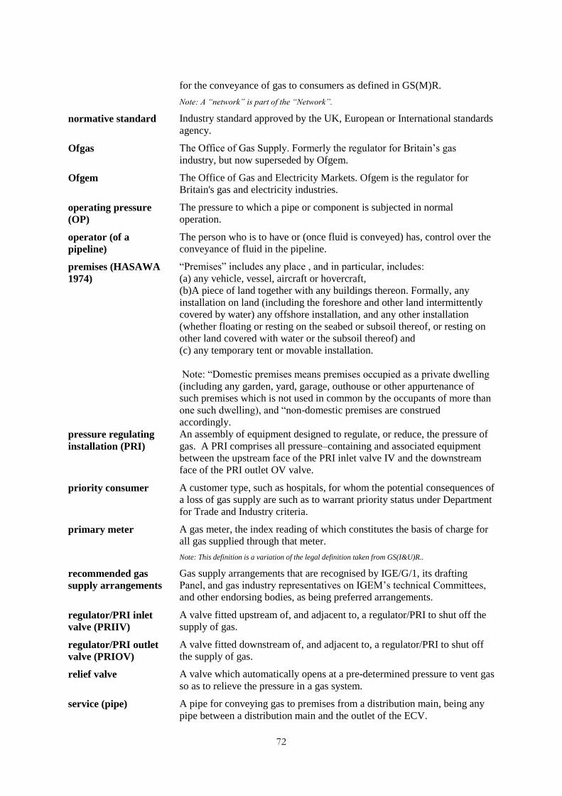
72
for the conveyance of gas to consumers as defined in GS(M)R.
Note: A “network” is part of the “Network”.
normative standard
Industry standard approved by the UK, European or International standards
agency.
Ofgas The Office of Gas Supply. Formerly the regulator for Britain‟s gas
industry, but now superseded by Ofgem.
Ofgem The Office of Gas and Electricity Markets. Ofgem is the regulator for
Britain's gas and electricity industries.
operating pressure
(OP)
The pressure to which a pipe or component is subjected in normal
operation.
operator (of a
pipeline)
The person who is to have or (once fluid is conveyed) has, control over the
conveyance of fluid in the pipeline.
premises (HASAWA
1974)
“Premises” includes any place , and in particular, includes:
(a) any vehicle, vessel, aircraft or hovercraft,
(b)A piece of land together with any buildings thereon. Formally, any
installation on land (including the foreshore and other land intermittently
covered by water) any offshore installation, and any other installation
(whether floating or resting on the seabed or subsoil thereof, or resting on
other land covered with water or the subsoil thereof) and
(c) any temporary tent or movable installation.
Note: “Domestic premises means premises occupied as a private dwelling
(including any garden, yard, garage, outhouse or other appurtenance of
such premises which is not used in common by the occupants of more than
one such dwelling), and “non-domestic premises are construed
accordingly.
pressure regulating
installation (PRI)
An assembly of equipment designed to regulate, or reduce, the pressure of
gas. A PRI comprises all pressure–containing and associated equipment
between the upstream face of the PRI inlet valve IV and the downstream
face of the PRI outlet OV valve.
priority consumer A customer type, such as hospitals, for whom the potential consequences of
a loss of gas supply are such as to warrant priority status under Department
for Trade and Industry criteria.
primary meter A gas meter, the index reading of which constitutes the basis of charge for
all gas supplied through that meter.
Note: This definition is a variation of the legal definition taken from GS(I&U)R..
recommended gas
supply arrangements
Gas supply arrangements that are recognised by IGE/G/1, its drafting
Panel, and gas industry representatives on IGEM‟s technical Committees,
and other endorsing bodies, as being preferred arrangements.
regulator/PRI inlet
valve (PRIIV)
A valve fitted upstream of, and adjacent to, a regulator/PRI to shut off the
supply of gas.
regulator/PRI outlet
valve (PRIOV)
A valve fitted downstream of, and adjacent to, a regulator/PRI to shut off
the supply of gas.
relief valve A valve which automatically opens at a pre-determined pressure to vent gas
so as to relieve the pressure in a gas system.
service (pipe) A pipe for conveying gas to premises from a distribution main, being any
pipe between a distribution main and the outlet of the ECV.
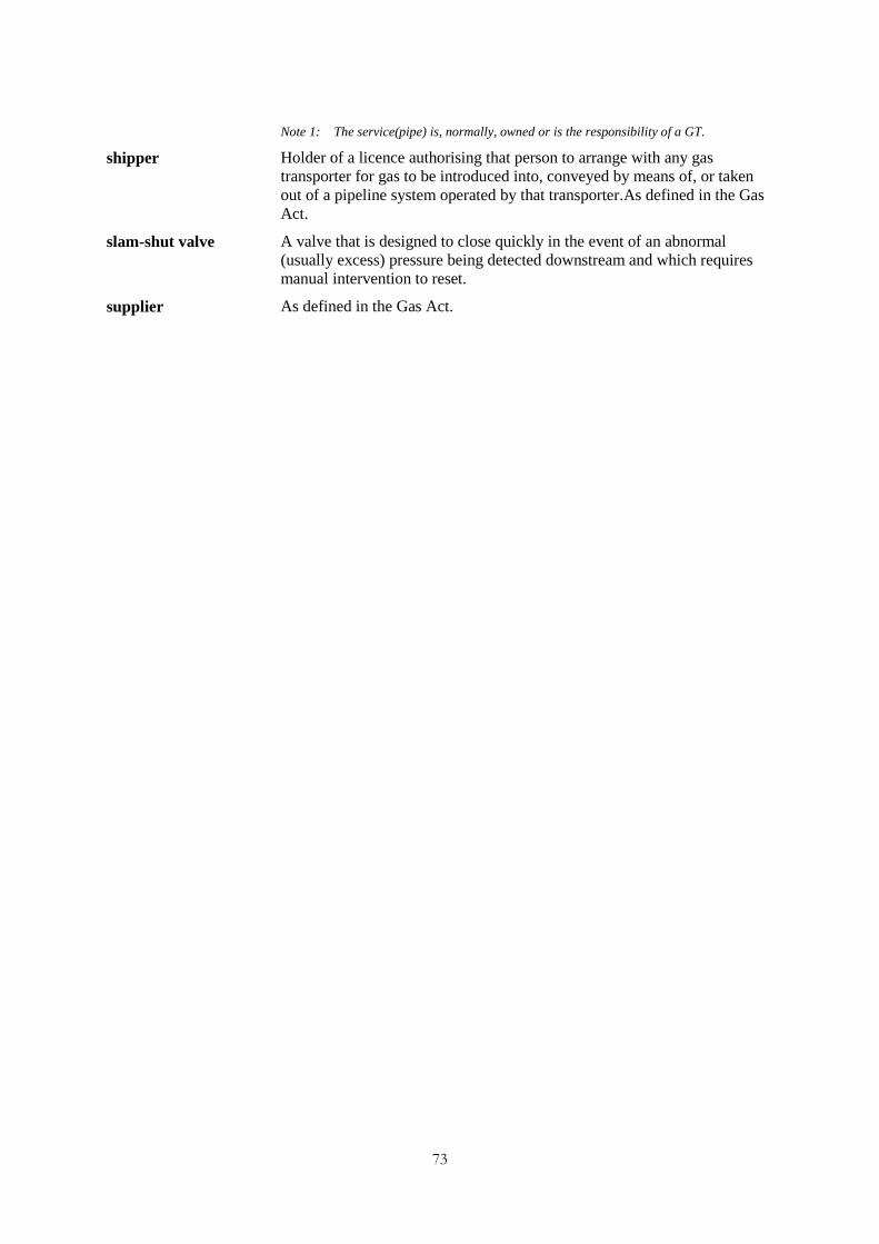
73
Note 1: The service(pipe) is, normally, owned or is the responsibility of a GT.
shipper Holder of a licence authorising that person to arrange with any gas
transporter for gas to be introduced into, conveyed by means of, or taken
out of a pipeline system operated by that transporter.As defined in the Gas
Act.
slam-shut valve A valve that is designed to close quickly in the event of an abnormal
(usually excess) pressure being detected downstream and which requires
manual intervention to reset.
supplier As defined in the Gas Act.

74
Annex 5: Connection and Disconnection Notification – Information
Requirements
RGMA Processes and Data provides standards for information to be passed to relevant market
participants to meet the GM(C&D)R. The Regulations require the following information:
1 Relevant Gas Supplier (or Gas Transporter)
Contact and Address.
2 Description of Work
connect a meter
disconnect a meter
disconnect a meter and then connect a meter with and/or from a service pipe through
which gas is conveyed to premises.
3 Further Information Relating to the Connection and/or Disconnection:
Details of proposed connection and/or disconnection:
(a) time..........am/pm/..........(day)/..........(month)/..........(year); and
(b) place..........(no. (if any) and street)..........(town)..........(postcode)
Any meter-point reference number or code which the person making the connection or
disconnection reasonably believes to have been assigned by a public gas transporter for
identifying the point at which the meter measures the gas conveyed by the GT.
4 Contractor Details:
The name of the person undertaking the connection and/or disconnection.
In the case of a connection, whether the person making the connection is an approved person
within the meaning of Condition 22(6) of the Standard Conditions of Gas Suppliers' Licences.
5 Meter Information:
Connection and Disconnection
The register(s) of the meter(s) at the time of the connection and or disconnection.
In the case of a connection, where known, the following details should be recorded:
(a) type and model of the meter
(b) whether the meter is a pre-payment meter
(c) manufacturer of the meter
(d) year of manufacture of the meter
(e) serial number of the meter
(f) measuring capacity of the meter
(g) units in which the register of the meter is expressed, including any multiplication
factor for the number of units
(h) the name and address of the owner of the meter.

75
In the case of a disconnection, where known, the serial number of the meter should be
recorded.
6 Other Devices (“Converter”):
Connection:
(a) model of the converter
(b) manufacturer of the converter
(c) year of manufacture of the converter
(d) serial number of the converter
(e) the converted and (if appropriate) any unconverted reading of the register of the
converter at the time of connection
(f) which one or more of the following the converter operates in respect of: temperature,
pressure, compressibility, density.
Disconnection:
(a) serial number of the converter
(b) the converted and (if appropriate) any unconverted reading of the register of the
converter at the time of disconnection.
7 By-passes
Whether a meter by-pass is fitted or proposed to be fitted at the time of the connection or
disconnection.
8 Meter Collars
Whether a meter collar is fitted, or proposed to be fitted, at the time of the connection or
disconnection.
9 Signature
Of, or of a person on behalf of, the person giving the notice, and in the latter case a statement
of the capacity of the signatory
10 Date of Notice
The date of the notice of the connection/disconnection shall be recorded.
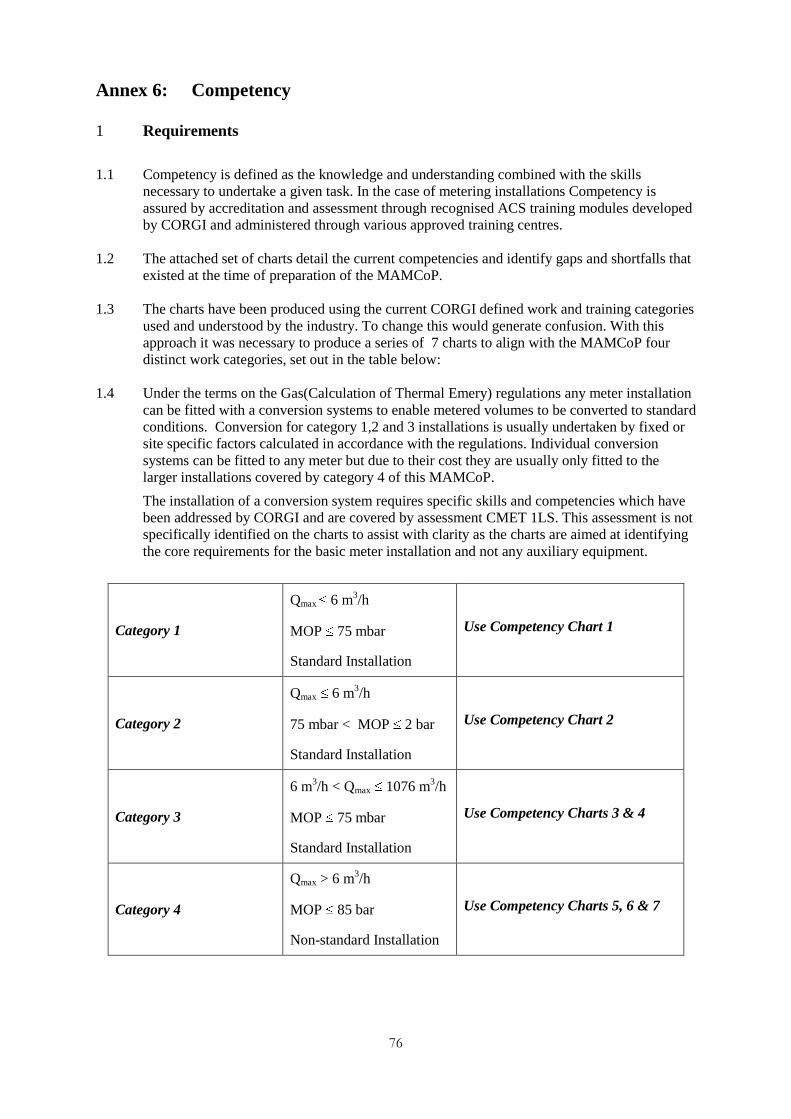
76
Annex 6: Competency
1 Requirements
1.1 Competency is defined as the knowledge and understanding combined with the skills
necessary to undertake a given task. In the case of metering installations Competency is
assured by accreditation and assessment through recognised ACS training modules developed
by CORGI and administered through various approved training centres.
1.2 The attached set of charts detail the current competencies and identify gaps and shortfalls that
existed at the time of preparation of the MAMCoP.
1.3 The charts have been produced using the current CORGI defined work and training categories
used and understood by the industry. To change this would generate confusion. With this
approach it was necessary to produce a series of 7 charts to align with the MAMCoP four
distinct work categories, set out in the table below:
1.4 Under the terms on the Gas(Calculation of Thermal Emery) regulations any meter installation
can be fitted with a conversion systems to enable metered volumes to be converted to standard
conditions. Conversion for category 1,2 and 3 installations is usually undertaken by fixed or
site specific factors calculated in accordance with the regulations. Individual conversion
systems can be fitted to any meter but due to their cost they are usually only fitted to the
larger installations covered by category 4 of this MAMCoP.
The installation of a conversion system requires specific skills and competencies which have
been addressed by CORGI and are covered by assessment CMET 1LS. This assessment is not
specifically identified on the charts to assist with clarity as the charts are aimed at identifying
the core requirements for the basic meter installation and not any auxiliary equipment.
Category 1
Qmax 6 m3/h
MOP 75 mbar
Standard Installation
Use Competency Chart 1
Category 2
Qmax 6 m3/h
75 mbar < MOP 2 bar
Standard Installation
Use Competency Chart 2
Category 3
6 m3/h < Qmax 1076 m
3/h
MOP 75 mbar
Standard Installation
Use Competency Charts 3 & 4
Category 4
Qmax > 6 m3/h
MOP 85 bar
Non-standard Installation
Use Competency Charts 5, 6 & 7

77
Note: The charts clearly highlight the following:
1 The need to develop a new ACS Assessment to cover Medium Pressure Domestic installations based on BS
6400 Part 2.
2 The need to develop a new ACS Assessment to cover Medium Pressure Large Domestic and Commercial
installations based on IGE/GM/8 and a simplified version of IGE/UP/1.
3 The need to develop a new ACS Assessment to cover Medium Pressure Commercial installations based on
IGE/GM/8.
4 The need to develop a new ACS Assessment to cover Commercial installations operating at pressures between
2 and 38 bar based on IGE/GM/8.
5 There are no ACS Assessments for any meter work where the operating pressures exceed 7 bar.

78
2. Competency Charts
2.1 ACS Assessment Codes and Descriptions
Chart 1 - Low Pressure Domestic – Standard Installations
Qmax ≤ 6 m3/hr MOP ≤ 75 mbar
Chart 2 - Medium Pressure Domestic - Standard Installations
Qmax ≤ 6 m3/hr MOP ≥ 75 mbar ≤ 2 bar
Chart 3 - Low Pressure Large Domestic & Small Industrial and Commercial - Standard
Installations
Qmax ≥ 6 m3/hr ≤ 40 m
3/hr MOP ≤ 75 mbar (up to U40 Diaphragm meter
fitted on anacondas)
Chart 4 - Low Pressure Industrial and Commercial - Standard Installations
Qmax > 40 m3/hr MOP ≤ 75 mbar (Above U40 Diaphragm meter & RPDs
fitted on flanges with optional by-pass)
Chart 5 - Medium Pressure Large Domestic & Small Industrial and Commercial
Installations
Qmax ≥ 6 m3/hr MOP ≤ 2 bar (up to U40 diaphragm meter fitted on
anacondas)
Chart 6 - Medium Pressure Industrial and Commercial Installations
Qmax ≥ 40 m3/hr MOP ≥ 75 mbar ≤ 2 bar (Above U40 diaphragm meter &
RPDs fitted on flanges with optional by-pass)
Chart 7 - Industrial & Commercial Installations
Qmax ≥ 6 m3/hr MOP > 2 bar ≤ 38 bar
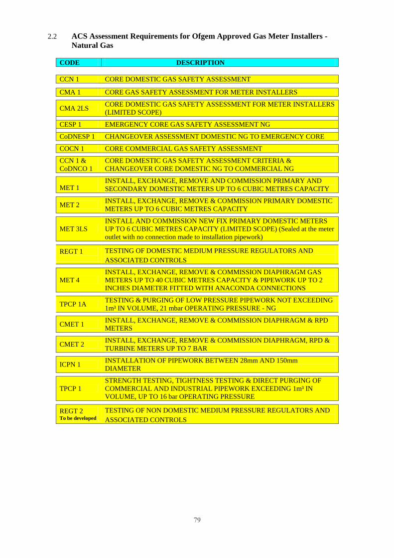
79
2.2 ACS Assessment Requirements for Ofgem Approved Gas Meter Installers -
Natural Gas
CODE DESCRIPTION
CCN 1 CORE DOMESTIC GAS SAFETY ASSESSMENT
CMA 1 CORE GAS SAFETY ASSESSMENT FOR METER INSTALLERS
CMA 2LS
CORE DOMESTIC GAS SAFETY ASSESSMENT FOR METER INSTALLERS
(LIMITED SCOPE)
CESP 1 EMERGENCY CORE GAS SAFETY ASSESSMENT NG
CoDNESP 1 CHANGEOVER ASSESSMENT DOMESTIC NG TO EMERGENCY CORE
COCN 1 CORE COMMERCIAL GAS SAFETY ASSESSMENT
CCN 1 &
CoDNCO 1
CORE DOMESTIC GAS SAFETY ASSESSMENT CRITERIA &
CHANGEOVER CORE DOMESTIC NG TO COMMERCIAL NG
MET 1 INSTALL, EXCHANGE, REMOVE AND COMMISSION PRIMARY AND
SECONDARY DOMESTIC METERS UP TO 6 CUBIC METRES CAPACITY
MET 2
INSTALL, EXCHANGE, REMOVE & COMMISSION PRIMARY DOMESTIC
METERS UP TO 6 CUBIC METRES CAPACITY
MET 3LS
INSTALL AND COMMISSION NEW FIX PRIMARY DOMESTIC METERS
UP TO 6 CUBIC METRES CAPACITY (LIMITED SCOPE) (Sealed at the meter
outlet with no connection made to installation pipework)
REGT 1
TESTING OF DOMESTIC MEDIUM PRESSURE REGULATORS AND
ASSOCIATED CONTROLS
MET 4
INSTALL, EXCHANGE, REMOVE & COMMISSION DIAPHRAGM GAS
METERS UP TO 40 CUBIC METRES CAPACITY & PIPEWORK UP TO 2
INCHES DIAMETER FITTED WITH ANACONDA CONNECTIONS
TPCP 1A
TESTING & PURGING OF LOW PRESSURE PIPEWORK NOT EXCEEDING
1m³ IN VOLUME, 21 mbar OPERATING PRESSURE - NG
CMET 1
INSTALL, EXCHANGE, REMOVE & COMMISSION DIAPHRAGM & RPD
METERS
CMET 2
INSTALL, EXCHANGE, REMOVE & COMMISSION DIAPHRAGM, RPD &
TURBINE METERS UP TO 7 BAR
ICPN 1
INSTALLATION OF PIPEWORK BETWEEN 28mm AND 150mm
DIAMETER
TPCP 1
STRENGTH TESTING, TIGHTNESS TESTING & DIRECT PURGING OF
COMMERCIAL AND INDUSTRIAL PIPEWORK EXCEEDING 1m³ IN
VOLUME, UP TO 16 bar OPERATING PRESSURE
REGT 2 To be developed
TESTING OF NON DOMESTIC MEDIUM PRESSURE REGULATORS AND
ASSOCIATED CONTROLS

80
Work Category Pre-Requisite ACS Core
Assessments Specific ACS Assessments New ACS Assessments
Domestic Primary & Secondary Meters
Domestic Primary Meters
Domestic Primary Meter fitted in box with meter left capped
at outlet
CCN 1.
CMA 1.
CMA 2LS.
Limited Scope
MET 1.
MET 2. Primary Only
MET 3LS. Primary Only
None Required
None Required
None Required
Chart 1.Low Pressure Domestic – Standard Installations Qmax ≤ 6m³/hr MOP ≤ 75 mbar
Note: CESP1. or CoDNESP1. can be used as an alternative core to CMA1.
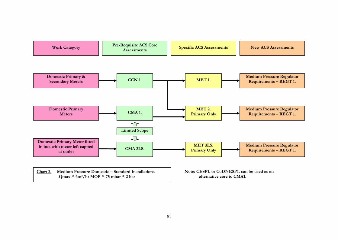
81
Work Category Pre-Requisite ACS Core
Assessments Specific ACS Assessments New ACS Assessments
Domestic Primary & Secondary Meters
Domestic Primary Meters
Domestic Primary Meter fitted in box with meter left capped
at outlet
CCN 1.
CMA 1.
CMA 2LS.
Limited Scope
MET 1.
MET 2. Primary Only
MET 3LS. Primary Only
Chart 2. Medium Pressure Domestic – Standard Installations Qmax ≤ 6m³/hr MOP ≥ 75 mbar ≤ 2 bar
Medium Pressure Regulator Requirements – REGT 1.
Medium Pressure Regulator Requirements – REGT 1.
Medium Pressure Regulator Requirements – REGT 1.
Note: CESP1. or CoDNESP1. can be used as an alternative core to CMA1.

82
Work Category
Pre-Requisite ACS Core Assessments
Specific ACS Assessments New ACS Assessments
Domestic Premise Only
Small Commercial Premise Only
Domestic & Small Commercial Premise
CMA 1. or CCN 1.
CMA 1. or CCN 1. & CoDNCO 1.
or COCN 1.
CMA 1. or CCN 1. & CoDNCO1. or COCN 1.
MET 4.*
TPCP 1A.
Chart 3. Low Pressure Large Domestic & Small Commercial Standard Installations Qmax ≥ 6m³/hr MOP ≤ 75 mbar
(Diaphragm Meters up to U40 fitted on anacondas including Testing & Purging of Natural gas low pressure installations up to 1m³ in volume)
Note: CESP1. or CoDNESP1. can be used as an alternative core to CMA1.
None Required
* An operative holding MET 4. does not also require MET 2. to install U6 primary meters.
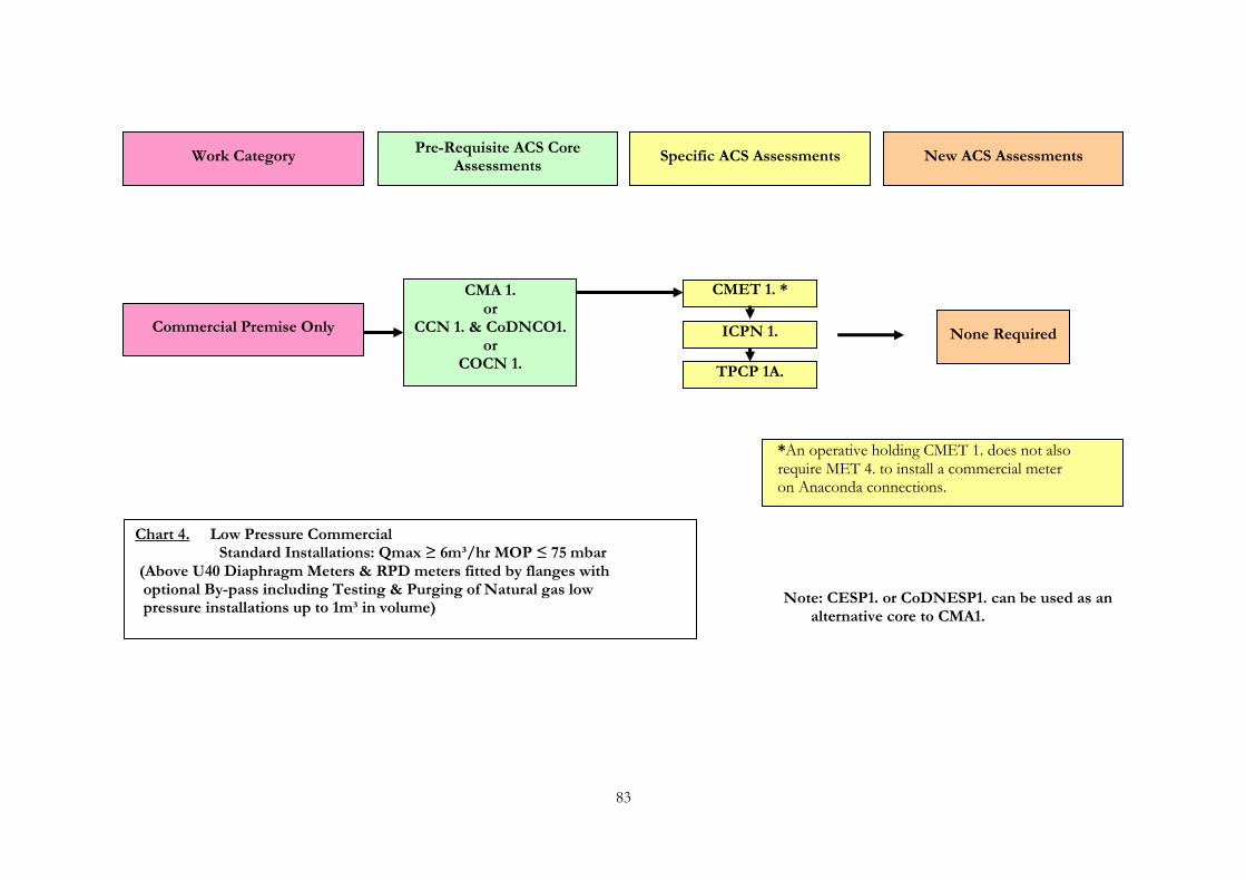
83
Work Category Pre-Requisite ACS Core
Assessments Specific ACS Assessments New ACS Assessments
Commercial Premise Only
CMA 1. or
CCN 1. & CoDNCO1. or
COCN 1.
CMET 1. *
ICPN 1.
TPCP 1A.
None Required
Chart 4. Low Pressure Commercial Standard Installations: Qmax ≥ 6m³/hr MOP ≤ 75 mbar
(Above U40 Diaphragm Meters & RPD meters fitted by flanges with optional By-pass including Testing & Purging of Natural gas low pressure installations up to 1m³ in volume)
Note: CESP1. or CoDNESP1. can be used as an alternative core to CMA1.
*An operative holding CMET 1. does not also require MET 4. to install a commercial meter on Anaconda connections.

84
Work Category Pre-Requisite ACS Core
Assessments Specific ACS Assessments New ACS Assessments
Large Domestic Premise Only
Small Commercial Premise Only
Large Domestic & Small Commercial Premise
CMA 1. or CCN 1.
CMA 1. or CCN 1. & CoDNCO 1.
or COCN 1.
CMA 1. or CCN 1. & CoDNCO 1.
or COCN 1.
MET 4.
Chart 5. Medium Pressure Large Domestic & Small Commercial Installations: Qmax ≥ 6m³/hr MOP ≤ 2 bar
(Diaphragm Meters up to U40 fitted on anacondas)
Note: CESP1. or CoDNESP1. can be used as an alternative core to CMA1.
New assessment to be developed from IGE/GM/8
New tightness test required (IGE/UP/1C) or use TPCP
1. (IGE/UP/1)

85
Work Category Pre-Requisite ACS Core
Assessments Specific ACS Assessments New ACS Assessments
Commercial Premise Only
CMA 1. or
CCN 1. & CoDNCO1. or
COCN 1.
CMET 1. *
ICPN 1.
TPCP 1.
Chart 6. Medium Pressure Commercial Installations Qmax ≥ 6m³/hr MOP ≥ 75 mbar ≤ 2 bar
(Above U40 Diaphragm Meters & RPD meters fitted by flanges with optional By-pass)
Note: CESP1. or CoDNESP1. can be used as an alternative core to CMA1.
*An operative holding CMET 1. does not also require MET 4. to install a commercial meter on Anaconda connections.
New assessment to be developed from IGE/GM/8
New tightness test required (IGE/UP/1C) or use TPCP
1. (IGE/UP/1)
Note: - CMET 1. covers above U40 Diaphragm & RPD Meters fitted on flanges with optional by-pass

86
Work Category Pre-Requisite ACS Core
Assessments Specific ACS Assessments New ACS Assessments
Commercial Premise Only
CMA 1. or
CCN 1. & CoDNCO1. or
COCN 1.
CMET 2.
ICPN 1.
TPCP 1.
Chart 7. Industrial & Commercial Installations Qmax ≥ 6m³/hr MOP ≥ 2 bar ≤ 85 bar
Note: CESP1. or CoDNESP1. can be used as an alternative core to CMA1.
New assessment to be developed from IGE/GM/8
New tightness test required (IGE/UP/1C) or use TPCP
1. (IGE/UP/1)
Note: - CMET 2. covers Diaphragm, RPD & Turbine Meters up to 16 bar No further ACS Assessments are available for this category Further assessments may be developed if identified by Industry or Ofgem (TSIG)
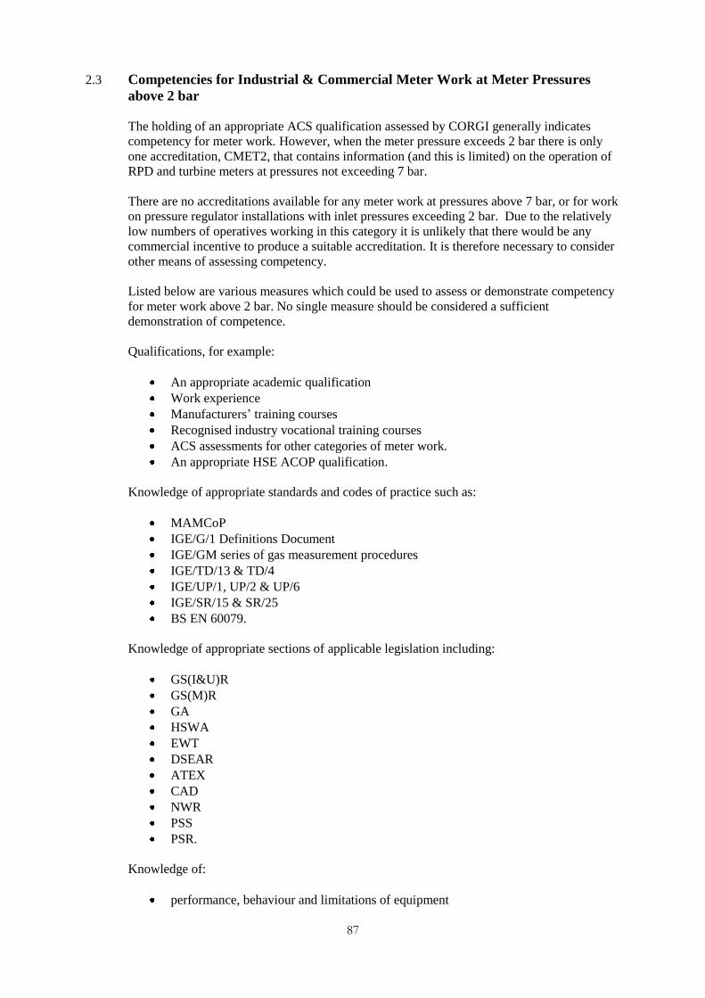
87
2.3 Competencies for Industrial & Commercial Meter Work at Meter Pressures
above 2 bar
The holding of an appropriate ACS qualification assessed by CORGI generally indicates
competency for meter work. However, when the meter pressure exceeds 2 bar there is only
one accreditation, CMET2, that contains information (and this is limited) on the operation of
RPD and turbine meters at pressures not exceeding 7 bar.
There are no accreditations available for any meter work at pressures above 7 bar, or for work
on pressure regulator installations with inlet pressures exceeding 2 bar. Due to the relatively
low numbers of operatives working in this category it is unlikely that there would be any
commercial incentive to produce a suitable accreditation. It is therefore necessary to consider
other means of assessing competency.
Listed below are various measures which could be used to assess or demonstrate competency
for meter work above 2 bar. No single measure should be considered a sufficient
demonstration of competence.
Qualifications, for example:
An appropriate academic qualification
Work experience
Manufacturers‟ training courses
Recognised industry vocational training courses
ACS assessments for other categories of meter work.
An appropriate HSE ACOP qualification.
Knowledge of appropriate standards and codes of practice such as:
MAMCoP
IGE/G/1 Definitions Document
IGE/GM series of gas measurement procedures
IGE/TD/13 & TD/4
IGE/UP/1, UP/2 & UP/6
IGE/SR/15 & SR/25
BS EN 60079.
Knowledge of appropriate sections of applicable legislation including:
GS(I&U)R
GS(M)R
GA
HSWA
EWT
DSEAR
ATEX
CAD
NWR
PSS
PSR.
Knowledge of:
performance, behaviour and limitations of equipment

88
commissioning processes
maintenance requirements of equipment
industrial plant design and operation
Adherence to an appropriate quality procedure which should include but not be limited to:
personal development programme
appraisal and authorisation systems
work activity and work management and recording systems.

89
Annex 7: Meter By-Pass Provision and Use
1 Requirements
1.1 This annex specifies the requirements for the:
provision of a by-pass
actions to be taken when a by-pass is operated
sealing of a by-pass valve
basis for estimating the quantity of gas when a by-pass is used by the MAM.
2 Definition of a Meter By-Pass
2.1 A meter by-pass comprises gas fittings through which the flow of gas can be diverted, so as
not to pass through the meter or metering equipment, and thereby secure the continued offtake
of gas in the event of any failure or maintenance of the meter or metering equipment which
would otherwise impede the flow of gas.
2.2 The meter by-pass must not by-pass the meter regulator or any other pressure control or
pressure protection device which comprises the meter installation.
3 Purpose of a Meter By-Pass
3.1 A meter by-pass may be used to:
provide a ready method of maintaining a supply of gas should the meter fail and
insufficient gas is available to satisfy the agreed maximum flow rate at the meter point;
and/or
allow a meter to be replaced, recalibrated, checked or maintained without interruption to
the gas supply.
4 Provision of a Meter By-pass
4.1 A meter by-pass would normally be considered where the provision of a meter by-pass would,
in the gas supplier‟s opinion, be prudent in order to avoid the risk of personal injury or death
or damage to property (including prejudice to animal welfare) arising from a fault on the
meter or metering equipment and where gas is supplied to the following types of premises:
(a) hospitals
(b) institutionalised accommodation (for example homes for the elderly, schools, and
prisons)
(c) premises utilising large or complex plant supporting continuous bulk manufacturing
(for example agricultural, baking or other commercial processes) and in analogous
circumstances
(d) and at meter installations connected to:
exceptionally extensive and complex pipework and gas consuming plant
multi-occupied premises or a number of discrete consumers (for example a
single meter installation serving a block of flats).
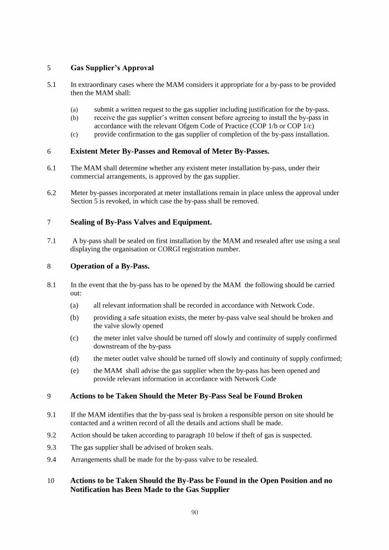
90
5 Gas Supplier‟s Approval
5.1 In extraordinary cases where the MAM considers it appropriate for a by-pass to be provided
then the MAM shall:
(a) submit a written request to the gas supplier including justification for the by-pass.
(b) receive the gas supplier‟s written consent before agreeing to install the by-pass in
accordance with the relevant Ofgem Code of Practice (COP 1/b or COP 1/c)
(c) provide confirmation to the gas supplier of completion of the by-pass installation.
6 Existent Meter By-Passes and Removal of Meter By-Passes.
6.1 The MAM shall determine whether any existent meter installation by-pass, under their
commercial arrangements, is approved by the gas supplier.
6.2 Meter by-passes incorporated at meter installations remain in place unless the approval under
Section 5 is revoked, in which case the by-pass shall be removed.
7 Sealing of By-Pass Valves and Equipment.
7.1 A by-pass shall be sealed on first installation by the MAM and resealed after use using a seal
displaying the organisation or CORGI registration number.
8 Operation of a By-Pass.
8.1 In the event that the by-pass has to be opened by the MAM the following should be carried
out:
(a) all relevant information shall be recorded in accordance with Network Code.
(b) providing a safe situation exists, the meter by-pass valve seal should be broken and
the valve slowly opened
(c) the meter inlet valve should be turned off slowly and continuity of supply confirmed
downstream of the by-pass
(d) the meter outlet valve should be turned off slowly and continuity of supply confirmed;
(e) the MAM shall advise the gas supplier when the by-pass has been opened and
provide relevant information in accordance with Network Code
9 Actions to be Taken Should the Meter By-Pass Seal be Found Broken
9.1 If the MAM identifies that the by-pass seal is broken a responsible person on site should be
contacted and a written record of all the details and actions shall be made.
9.2 Action should be taken according to paragraph 10 below if theft of gas is suspected.
9.3 The gas supplier shall be advised of broken seals.
9.4 Arrangements shall be made for the by-pass valve to be resealed.
10 Actions to be Taken Should the By-Pass be Found in the Open Position and no
Notification has Been Made to the Gas Supplier

91
10.1 The responsible person on site must be advised that the by-pass has been found open. Both
the date and time of the notification and the time at which the by-pass was found to be open
must be recorded. If there is no apparent reason to why the by-pass is open, then arrangements
must be made with the gas supplier and consumer for the by-pass to be closed safely and the
by-pass valve resealed. If the by-pass is left open the purpose should be identified as to why
the by-pass is left open. In either circumstance the relevant gas supplier shall be notified.
10.2 Where the MAM suspects that there has been theft of gas then the relevant gas supplier shall
be notified.
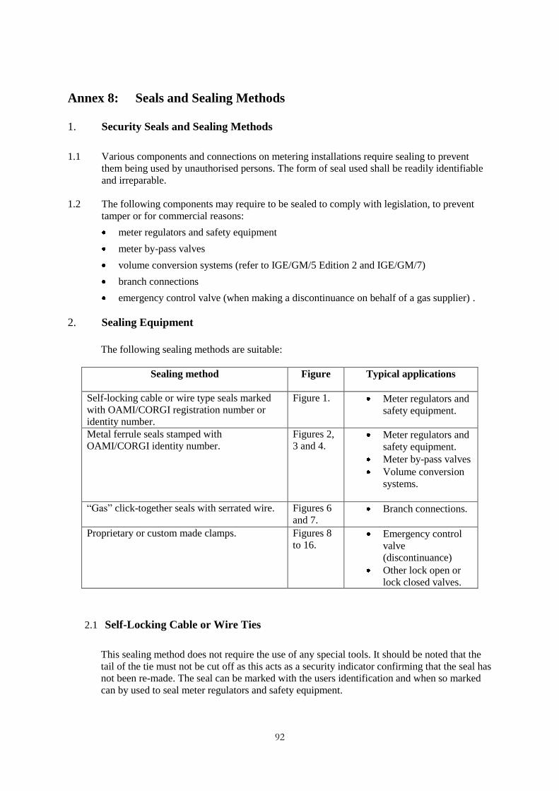
92
Annex 8: Seals and Sealing Methods
1. Security Seals and Sealing Methods
1.1 Various components and connections on metering installations require sealing to prevent
them being used by unauthorised persons. The form of seal used shall be readily identifiable
and irreparable.
1.2 The following components may require to be sealed to comply with legislation, to prevent
tamper or for commercial reasons:
meter regulators and safety equipment
meter by-pass valves
volume conversion systems (refer to IGE/GM/5 Edition 2 and IGE/GM/7)
branch connections
emergency control valve (when making a discontinuance on behalf of a gas supplier) .
2. Sealing Equipment
The following sealing methods are suitable:
Sealing method Figure
Typical applications
Self-locking cable or wire type seals marked
with OAMI/CORGI registration number or
identity number.
Figure 1. Meter regulators and
safety equipment.
Metal ferrule seals stamped with
OAMI/CORGI identity number.
Figures 2,
3 and 4. Meter regulators and
safety equipment.
Meter by-pass valves
Volume conversion
systems.
“Gas” click-together seals with serrated wire. Figures 6
and 7. Branch connections.
Proprietary or custom made clamps. Figures 8
to 16. Emergency control
valve
(discontinuance)
Other lock open or
lock closed valves.
2.1 Self-Locking Cable or Wire Ties
This sealing method does not require the use of any special tools. It should be noted that the
tail of the tie must not be cut off as this acts as a security indicator confirming that the seal has
not been re-made. The seal can be marked with the users identification and when so marked
can by used to seal meter regulators and safety equipment.
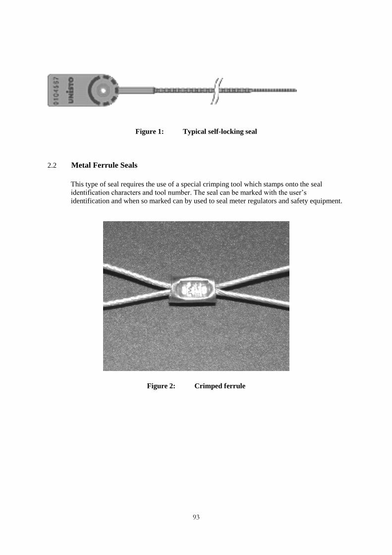
93
Figure 1: Typical self-locking seal
2.2 Metal Ferrule Seals
This type of seal requires the use of a special crimping tool which stamps onto the seal
identification characters and tool number. The seal can be marked with the user‟s
identification and when so marked can by used to seal meter regulators and safety equipment.
Figure 2: Crimped ferrule
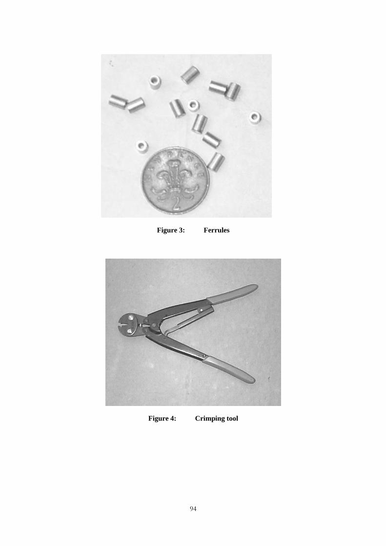
94
Figure 3: Ferrules
Figure 4: Crimping tool

95
Figure 5: Example of the sealing ferrule and smooth wire sealing
method on a butterfly meter by-pass valve.
2.3 “Gas” Click-Together Seal with Serrated wire
This type of seal does not require the use of any special tools but does require the use of
serrated wire.
Note: This type of seal is not suitable for sealing meter regulators and safety equipment, as it does not carry the
user’s identification.
Figure 6: Click-together seal (finger seal)

96
Figure 7: Serrated wire for use with seal as detailed in Figure 6
2.4 Proprietary or custom made clamps
Figure 8: Typical clamping kit for plug valves

97
Figure 9: Typical clamping kit fitted to a plug valve
Figure 10: Typical clamping kit for ball valves

98
Figure 11: Typical clamping kit fitted to a ball valve
Figure 12: Alternative disposable padlocks

99
Figure 13: Typical spin cap kit for sealing valves in domestic size semi concealed meter
installations.
Figure 14: Spin Cap assembly showing spin cap lock openings and tool for domestic size
semi-concealed meter installations.

100
Figure 15: Valve spindle cover.
Figure 16: Example of a valve spindle cover sealing fitted to a gate valve.
End of Document