Metallic – One-Piece Tray A157–A189 - tnb.ca · A159 T&B Cable Tray Metallic One-Piece Tray How...
33
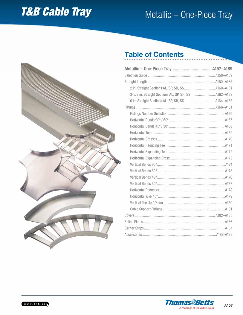
www.tnb.ca A157 Metallic – One-Piece Tray T&B Cable Tray Metallic – One-Piece Tray ................................... A157–A189 Selection Guide ........................................................................ A158–A159 Straight Lengths ....................................................................... A160–A165 2 in. Straight Sections AL, SP, SH, SS ................................. A160–A161 3-5/8 in. Straight Sections AL, SP, SH, SS .......................... A162–A163 6 in. Straight Sections AL, SP, SH, SS ................................. A164–A165 Fittings ..................................................................................... A166–A181 Fittings Number Selection............................................................. A166 Horizontal Bends 90º / 60º ........................................................... A167 Horizontal Bends 45º / 30º ........................................................... A168 Horizontal Tees ............................................................................. A169 Horizontal Crosses.........................................................................A170 Horizontal Reducing Tee ................................................................A171 Horizontal Expanding Tee...............................................................A172 Horizontal Expanding Cross ...........................................................A173 Vertical Bends 90º ......................................................................... A174 Vertical Bends 60º .........................................................................A175 Vertical Bends 45º .........................................................................A176 Vertical Bends 30º ........................................................................ A177 Horizontal Reducers.......................................................................A178 Horizontal Wye 45º ........................................................................A179 Vertical Tee Up / Down ................................................................. A180 Cable Support Fittings ...................................................................A181 Covers ...................................................................................... A182–A185 Splice Plates ....................................................................................... A186 Barrier Strips ...................................................................................... A187 Accessories ............................................................................... A188-A189 Table of Contents
Transcript of Metallic – One-Piece Tray A157–A189 - tnb.ca · A159 T&B Cable Tray Metallic One-Piece Tray How...
w w w . t n b . c a A157
Metallic – One-Piece Tray T&B Cable Tray
Metallic – One-Piece Tray ................................... A157–A189
Selection Guide ........................................................................ A158–A159
Straight Lengths ....................................................................... A160–A165
2 in. Straight Sections AL, SP, SH, SS ................................. A160–A161
3-5/8 in. Straight Sections AL, SP, SH, SS .......................... A162–A163
6 in. Straight Sections AL, SP, SH, SS ................................. A164–A165
Fittings ..................................................................................... A166–A181
Fittings Number Selection ............................................................. A166
Horizontal Bends 90º / 60º ........................................................... A167
Horizontal Bends 45º / 30º ........................................................... A168
Horizontal Tees ............................................................................. A169
Horizontal Crosses .........................................................................A170
Horizontal Reducing Tee ................................................................A171
Horizontal Expanding Tee...............................................................A172
Horizontal Expanding Cross ...........................................................A173
Vertical Bends 90º .........................................................................A174
Vertical Bends 60º .........................................................................A175
Vertical Bends 45º .........................................................................A176
Vertical Bends 30º ........................................................................ A177
Horizontal Reducers.......................................................................A178
Horizontal Wye 45º ........................................................................A179
Vertical Tee Up / Down ................................................................. A180
Cable Support Fittings ...................................................................A181
Covers ...................................................................................... A182–A185
Splice Plates ....................................................................................... A186
Barrier Strips ...................................................................................... A187
Accessories ............................................................................... A188-A189
Table of Contents
w w w . t n b . c aA158
Metallic – One-Piece Tray T&B Cable Tray
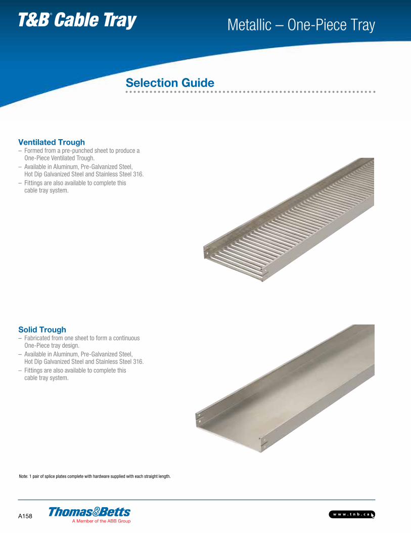
Note: 1 pair of splice plates complete with hardware supplied with each straight length.
Selection Guide
Ventilated Trough– Formed from a pre-punched sheet to produce a One-Piece Ventilated Trough.– Available in Aluminum, Pre-Galvanized Steel, Hot Dip Galvanized Steel and Stainless Steel 316.– Fittings are also available to complete this cable tray system.
Solid Trough– Fabricated from one sheet to form a continuous One-Piece tray design. – Available in Aluminum, Pre-Galvanized Steel, Hot Dip Galvanized Steel and Stainless Steel 316.– Fittings are also available to complete this cable tray system.

w w w . t n b . c a A159
Metallic – One-Piece Tray T&B Cable Tray
How to Create Part NumbersThomas & Betts has created a numbering system based on the order of selection criteria. For example the first selection issue is the environment which the cable tray will be subjected to. This selection will lead to the best material for your application. For complete details on cable tray selection process, see page A8.
Methods1. Select the material best suited to your environment. Refer to technical section page A8.2. Determine the tray series using the NEMA Load/Span Designations page A16, and Sizing Cable Tray page A23.3. Select nominal depth and width of tray based on Cable Loading. See Sizing Cable Tray page A23.4. Select the bottom type based on cables and spacing requirements.5. The last number is the length of the cable tray.
Straight Section Number Selection
(ALU13) 12V-3
Material Series Siderail Height (in.) Width Bottom Type Length
AL • AluminumSP • Pre-GalvanizedSH • Hot Dip GalvanizedSS • Stainless Steel 316
U1 • Unit or One-Piece Tray 2 • (2 in.)3 • (3-5/8 in.)6 • (6 in.)
06 • (6 in.)12 • (12 in.)18 • (18 in.)24 • (24 in.)
Welded Flat Rung30 • (30 in.)36 • (36 in.)
V • Ventilated TroughS • Solid Trough
3 •(3 meters) *
*3m = 9.842 ft.
Selection Guide

w w w . t n b . c aA160
Metallic – One-Piece Tray T&B Cable Tray
Straight Section Number Selection
(ALU12) 12V-3
Material Series Siderail Height (in.) Width Bottom Type Length
AL • AluminumSP • Pre-GalvanizedSH • Hot Dip GalvanizedSS • Stainless Steel 316
U1 • Unit or One-Piece Tray 2 • (2 in.) 06 • (6 in.)12 • (12 in.)18 • (18 in.)24 • (24 in.)
Welded Flat Rung30 • (30 in.)36 • (36 in.)
V • Ventilated TroughS • Solid Trough
3 • (3 meters) *
* Standard straight length is 10 feet nominal = actually 3 m. 1 m = 3.2808 ft. 3 m = 9.842 ft.
Technical SpecificationsAll calculations and data are based on 36 in. wide cable trays with rungs spaced on 12 in. centers with tray supported as simple spans with deflection measured at the midpoint. Continuous spans may reduce deflection by as much as 50%.
Deflection factor: For lighter loads, deflection at any length can be calculated by multiplying the load by the deflection factor.For Fittings consult pages A50 to A89.
SeriesSupport Span (Feet)
6 8 10 12 14 16 18 20
ALU12Load (lb.)/ft.) 69 39 25 – – – – –
Deflection (in.) 0.382 0.730 1.000 – – – – –
Deflection Factor 0.006 0.019 0.040 – – – – –
SPU12 SHU12
Load (lb.)/ft.) 69 39 25 – – – – –
Deflection (in.) 0.382 0.730 1.000 – – – – –
Deflection Factor 0.006 0.019 0.040 – – – – –
SSU12Load (lb.)/ft.) 69 39 25 – – – – –
Deflection (in.) 0.382 0.730 1.000 – – – – –
Deflection Factor 0.006 0.019 0.040 – – – – –
Prefix
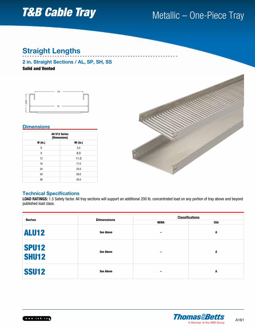
Straight Lengths2 in. Straight Sections / AL, SP, SH, SSSolid and Vented
w w w . t n b . c a A161
Metallic – One-Piece Tray T&B Cable Tray
DimensionsAll U12 Series(Dimensions)
W (in.) Wi (in.)
6 5.0
9 8.0
12 11.0
18 17.0
24 23.0
30 29.0
36 35.0
Technical SpecificationsLOAD RATINGS: 1.5 Safety factor. All tray sections will support an additional 200 lb. concentrated load on any portion of tray above and beyond published load class.
Series DimensionsClassifications
NEMA CSA
ALU12 See Above – A
SPU12 SHU12
See Above – A
SSU12 See Above – A
1.89
0
WI
W
Straight Lengths2 in. Straight Sections / AL, SP, SH, SSSolid and Vented

w w w . t n b . c aA162
Metallic – One-Piece Tray T&B Cable Tray
Straight Lengths3-5/8 in. Straight Sections / AL, SP, SH, SSSolid and Vented
Straight Section Number Selection
(ALU13) 12V-3
Material Series SiderailHeight (in.) Width Bottom Type Length
AL • AluminumSP • Pre-GalvanizedSH • Hot Dip GalvanizedSS • Stainless Steel 316
U1 • Unit or One-Piece Tray 2 • (2 in.) 06 • (6 in.)12 • (12 in.)18 • (18 in.)24 • (24 in.)30 • (30 in.)36 • (36 in.)
V • Ventilated TroughS • Solid Trough
3 •(3 meters) *
* Standard straight length is 10 feet nominal = actually 3 m. 1 m = 3.2808 ft. 3 m = 9.842 ft.
Technical SpecificationsAll calculations and data are based on 36 in. wide cable trays with tray supported as simple spans with deflection measured at the midpoint. Continuous spans may reduce deflection by as much as 50%.
Deflection factor: For lighter loads, deflection at any length can be calculated by multiplying the load by the deflection factor.For Fittings consult pages A50 to A89.
SeriesSupport Span (Feet)
6 8 10 12 14 16 18 20
ALU13Load (lb.)/ft.) 180 101 65 – – – – –
Deflection (in.) 0.382 0.430 0.540 – – – – –
Deflection Factor 0.002 0.004 0.008 – – – – –
SPU13 SHU13
Load (lb.)/ft.) 180 101 65 – – – – –
Deflection (in.) 0.125 0.250 0.320 – – – – –
Deflection Factor 0.001 0.002 0.005 – – – – –
SSU13Load (lb.)/ft.) 180 101 65 – – – – –
Deflection (in.) 0.125 0.250 0.320 – – – – –
Deflection Factor 0.001 0.002 0.005 – – – – –
Prefix

w w w . t n b . c a A163
Metallic – One-Piece Tray T&B Cable Tray
Straight Lengths3-5/8 in. Straight Sections / AL, SP, SH, SSSolid and Vented
3.62
5
WI
W
DimensionsAll U13 Series(Dimensions)
W (in.) Wi (in.)
6 5.0
9 8.0
12 11.0
18 17.0
24 23.0
30 29.0
36 35.0
Technical SpecificationsLOAD RATINGS: 1.5 Safety factor. All tray sections will support an additional 200 lb. concentrated load on any portion of tray above and beyond published load class.
Series DimensionsClassifications
NEMA CSA
ALU13 See Above 8C C
SPU13 SHU13
See Above 8C C
SSU13 See Above 8C C
w w w . t n b . c aA164
Metallic – One-Piece Tray T&B Cable Tray
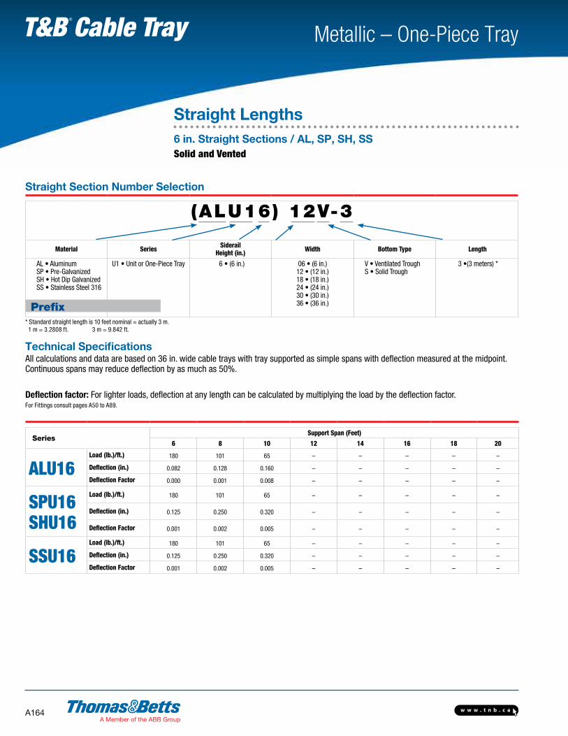
Straight Lengths6 in. Straight Sections / AL, SP, SH, SSSolid and Vented
Straight Section Number Selection
(ALU16) 12V-3
Material Series SiderailHeight (in.) Width Bottom Type Length
AL • AluminumSP • Pre-GalvanizedSH • Hot Dip GalvanizedSS • Stainless Steel 316
U1 • Unit or One-Piece Tray 6 • (6 in.) 06 • (6 in.)12 • (12 in.)18 • (18 in.)24 • (24 in.)30 • (30 in.)36 • (36 in.)
V • Ventilated TroughS • Solid Trough
3 •(3 meters) *
* Standard straight length is 10 feet nominal = actually 3 m. 1 m = 3.2808 ft. 3 m = 9.842 ft.
Technical SpecificationsAll calculations and data are based on 36 in. wide cable trays with tray supported as simple spans with deflection measured at the midpoint. Continuous spans may reduce deflection by as much as 50%.
Deflection factor: For lighter loads, deflection at any length can be calculated by multiplying the load by the deflection factor.For Fittings consult pages A50 to A89.
SeriesSupport Span (Feet)
6 8 10 12 14 16 18 20
ALU16Load (lb.)/ft.) 180 101 65 – – – – –
Deflection (in.) 0.082 0.128 0.160 – – – – –
Deflection Factor 0.000 0.001 0.008 – – – – –
SPU16 SHU16
Load (lb.)/ft.) 180 101 65 – – – – –
Deflection (in.) 0.125 0.250 0.320 – – – – –
Deflection Factor 0.001 0.002 0.005 – – – – –
SSU16Load (lb.)/ft.) 180 101 65 – – – – –
Deflection (in.) 0.125 0.250 0.320 – – – – –
Deflection Factor 0.001 0.002 0.005 – – – – –
Prefix
w w w . t n b . c a A165
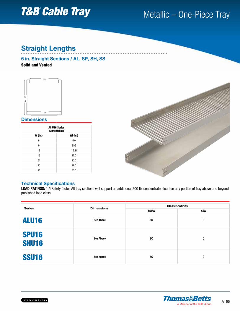
Metallic – One-Piece Tray T&B Cable Tray6.
188
WI
W
Straight Lengths6 in. Straight Sections / AL, SP, SH, SSSolid and Vented
Dimensions
All U16 Series (Dimensions)
W (in.) Wi (in.)
6 5.0
9 8.0
12 11.0
18 17.0
24 23.0
30 29.0
36 35.0
Technical SpecificationsLOAD RATINGS: 1.5 Safety factor. All tray sections will support an additional 200 lb. concentrated load on any portion of tray above and beyond published load class.
Series DimensionsClassifications
NEMA CSA
ALU16 See Above 8C C
SPU16 SHU16
See Above 8C C
SSU16 See Above 8C C

w w w . t n b . c aA166
Metallic – One-Piece Tray T&B Cable Tray
FittingsFittings Number Selection
Fitting Number Selection
SHUF306VHB9012
Fitting Material Siderail Depth Width Bottom Type Fitting Type Angle** Nominal Radius †
ALUF • AluminumSPUF • Pre-Galvanized FittingsSHUF • Hot Dip Galvanized FittingsSSUF • Stainless Steel 316
2 • (2 in.)3 • (3-5/8 in.)
6 • (6 in.)
06 • (6 in.)12 • (12 in.)18 • (18 in.)24 • (24 in.)30 • (30 in.)36 • (36 in.)
V • Ventilated S • Solid Trough
HB • Horizontal BendHT • Horizontal TeeHX • Horizontal CrossVI • Vertical Inside BendVO • Vertical Outside BendHYR • Horizontal Wye RightHYL • Horizontal Wye LeftRT • Horizontal Reducing TeeET • Horizontal Expanding TeeEX • Horizontal Expand CrossHLR • Horizontal Left ReducerHSR • Horizontal Straight ReducerHRR • Horizontal Right Reducer
30 • (30°)45 • (45°)60 • (60°)90 • (90°)
12 • (12 in.)24 • (24 in.)36 • (36 in.)
* Angle is required for HB, VI, VO only.† Radius is not required for the following Fitting Types: HYR, HYL, HLR, HRR, HSR
Prefix
w w w . t n b . c a A167
Metallic – One-Piece Tray T&B Cable Tray
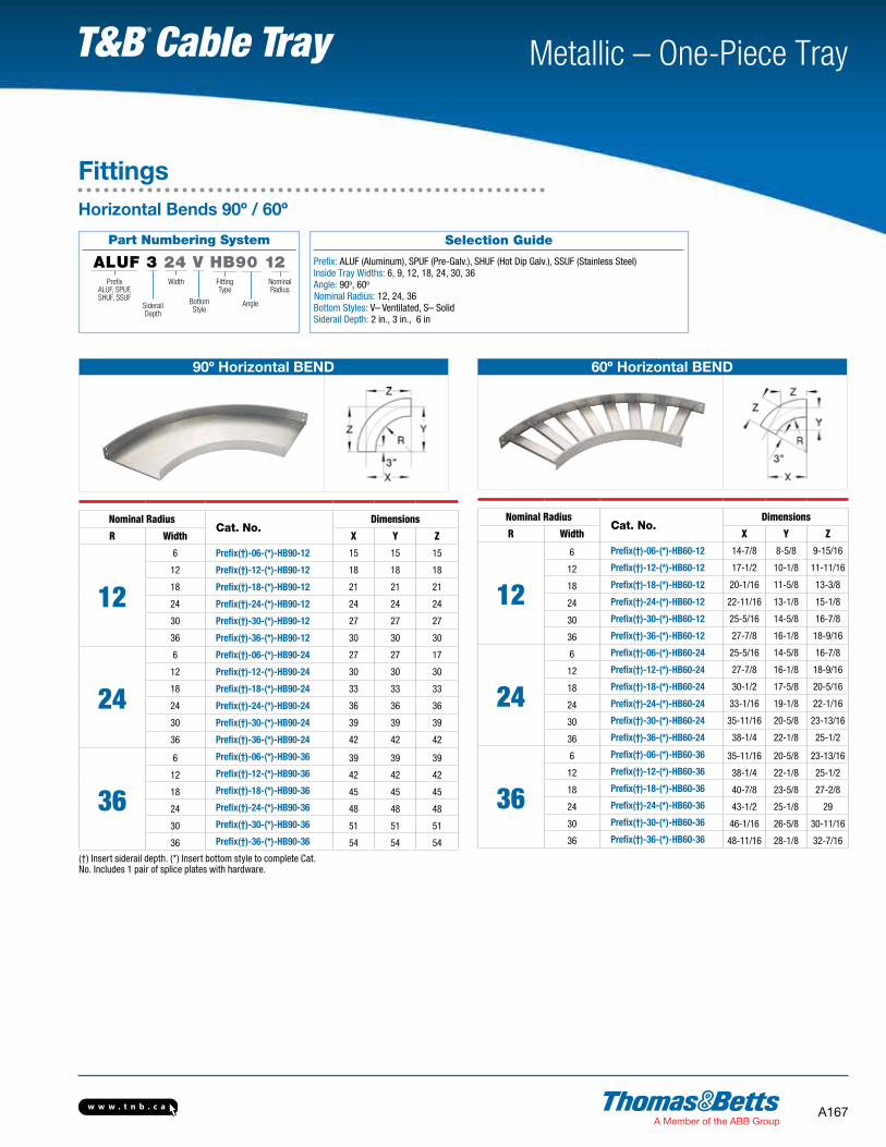
90º Horizontal BEND
Nominal RadiusCat. No.
Dimensions
R Width X Y Z
12
6 Prefix(†)-06-(*)-HB90-12 15 15 15
12 Prefix(†)-12-(*)-HB90-12 18 18 18
18 Prefix(†)-18-(*)-HB90-12 21 21 21
24 Prefix(†)-24-(*)-HB90-12 24 24 24
30 Prefix(†)-30-(*)-HB90-12 27 27 27
36 Prefix(†)-36-(*)-HB90-12 30 30 30
24
6 Prefix(†)-06-(*)-HB90-24 27 27 17
12 Prefix(†)-12-(*)-HB90-24 30 30 30
18 Prefix(†)-18-(*)-HB90-24 33 33 33
24 Prefix(†)-24-(*)-HB90-24 36 36 36
30 Prefix(†)-30-(*)-HB90-24 39 39 39
36 Prefix(†)-36-(*)-HB90-24 42 42 42
36
6 Prefix(†)-06-(*)-HB90-36 39 39 39
12 Prefix(†)-12-(*)-HB90-36 42 42 42
18 Prefix(†)-18-(*)-HB90-36 45 45 45
24 Prefix(†)-24-(*)-HB90-36 48 48 48
30 Prefix(†)-30-(*)-HB90-36 51 51 51
36 Prefix(†)-36-(*)-HB90-36 54 54 54
(†) Insert siderail depth. (*) Insert bottom style to complete Cat. No. Includes 1 pair of splice plates with hardware.
60º Horizontal BEND
Nominal RadiusCat. No.
Dimensions
R Width X Y Z
12
6 Prefix(†)-06-(*)-HB60-12 14-7/8 8-5/8 9-15/16
12 Prefix(†)-12-(*)-HB60-12 17-1/2 10-1/8 11-11/16
18 Prefix(†)-18-(*)-HB60-12 20-1/16 11-5/8 13-3/8
24 Prefix(†)-24-(*)-HB60-12 22-11/16 13-1/8 15-1/8
30 Prefix(†)-30-(*)-HB60-12 25-5/16 14-5/8 16-7/8
36 Prefix(†)-36-(*)-HB60-12 27-7/8 16-1/8 18-9/16
24
6 Prefix(†)-06-(*)-HB60-24 25-5/16 14-5/8 16-7/8
12 Prefix(†)-12-(*)-HB60-24 27-7/8 16-1/8 18-9/16
18 Prefix(†)-18-(*)-HB60-24 30-1/2 17-5/8 20-5/16
24 Prefix(†)-24-(*)-HB60-24 33-1/16 19-1/8 22-1/16
30 Prefix(†)-30-(*)-HB60-24 35-11/16 20-5/8 23-13/16
36 Prefix(†)-36-(*)-HB60-24 38-1/4 22-1/8 25-1/2
36
6 Prefix(†)-06-(*)-HB60-36 35-11/16 20-5/8 23-13/16
12 Prefix(†)-12-(*)-HB60-36 38-1/4 22-1/8 25-1/2
18 Prefix(†)-18-(*)-HB60-36 40-7/8 23-5/8 27-2/8
24 Prefix(†)-24-(*)-HB60-36 43-1/2 25-1/8 29
30 Prefix(†)-30-(*)-HB60-36 46-1/16 26-5/8 30-11/16
36 Prefix(†)-36-(*)-HB60-36 48-11/16 28-1/8 32-7/16
Selection Guide
Prefix: ALUF (Aluminum), SPUF (Pre-Galv.), SHUF (Hot Dip Galv.), SSUF (Stainless Steel)
Inside Tray Widths: 6, 9, 12, 18, 24, 30, 36 Angle: 90o, 60o
Nominal Radius: 12, 24, 36Bottom Styles: V– Ventilated, S– SolidSiderail Depth: 2 in., 3 in., 6 in
FittingsHorizontal Bends 90º / 60º
Part Numbering System
ALUF 3 24 V HB90 12Prefix
ALUF, SPUF,SHUF, SSUF
FittingType
NominalRadius
Width
SiderailDepth
Bottom Style
Angle
w w w . t n b . c aA168
Metallic – One-Piece Tray T&B Cable Tray
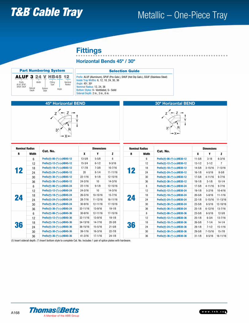
Part Numbering System
ALUF 3 24 V HB45 12Prefix
ALUF, SPUF,SHUF, SSUF
FittingType
NominalRadius
Width
SiderailDepth
Bottom Style
Angle
FittingsHorizontal Bends 45º / 30º
45º Horizontal BEND
Nominal RadiusCat. No.
Dimensions
R Width X Y Z
12
6 Prefix(†)-06-(*)-(+)HB45-12 13-5/8 5-5/8 8
12 Prefix(†)-12-(*)-(+)HB45-12 15-3/4 6-1/2 9-3/16
18 Prefix(†)-18-(*)-(+)HB45-12 17-7/8 7-3/8 10-7/16
24 Prefix(†)-24-(*)-(+)HB45-12 20 8-1/4 11-11/16
30 Prefix(†)-30-(*)-(+)HB45-12 22-1/16 9-1/8 12-15/16
36 Prefix(†)-36-(*)-(+)HB45-12 24-3/16 10 14-3/16
24
6 Prefix(†)-06-(*)-(+)HB45-24 22-1/16 9-1/8 12-15/16
12 Prefix(†)-12-(*)-(+)HB45-24 24-3/16 10 14-3/16
18 Prefix(†)-18-(*)-(+)HB45-24 26-5/16 10-15/16 15-7/16
24 Prefix(†)-24-(*)-(+)HB45-24 28-7/16 11-13/16 16-11/16
30 Prefix(†)-30-(*)-(+)HB45-24 30-9/16 12-11/16 17-15/16
36 Prefix(†)-36-(*)-(+)HB45-24 32-11/16 13-9/16 19-1/8
36
6 Prefix(†)-06-(*)-(+)HB45-36 30-9/16 12-11/16 17-15/16
12 Prefix(†)-12-(*)-(+)HB45-36 32-11/16 13-9/16 19-1/8
18 Prefix(†)-18-(*)-(+)HB45-36 34-13/16 14-7/16 20-3/8
24 Prefix(†)-24-(*)-(+)HB45-36 36-15/16 15-5/16 21-5/8
30 Prefix(†)-30-(*)-(+)HB45-36 39-1/16 16-3/16 22-7/8
36 Prefix(†)-36-(*)-(+)HB45-36 41-3/16 17-1/16 24-1/8
(†) Insert siderail depth. (*) Insert bottom style to complete Cat. No. Includes 1 pair of splice plates with hardware.
30º Horizontal BEND
Nominal RadiusCat. No.
Dimensions
R Width X Y Z
12
6 Prefix(†)-06-(*)-(+)HB30-12 11-5/8 3-18 6-3/16
12 Prefix(†)-12-(*)-(+)HB30-12 13-1/2 3-1/2 7
18 Prefix(†)-18-(*)-(+)HB30-12 14-5/8 3-15/16 7-13/16
24 Prefix(†)-24-(*)-(+)HB30-12 16-1/8 4-5/16 8-5/8
30 Prefix(†)-30-(*)-(+)HB30-12 17-5/8 4-11/16 9-7/16
36 Prefix(†)-36-(*)-(+)HB30-12 19-1/8 5-1/8 10-1/4
24
6 Prefix(†)-06-(*)-(+)HB30-24 17-5/8 4-11/16 9-7/16
12 Prefix(†)-12-(*)-(+)HB30-24 19-1/8 5-2/16 10-4/16
18 Prefix(†)-18-(*)-(+)HB30-24 20-5/8 5-8/16 11-1/16
24 Prefix(†)-24-(*)-(+)HB30-24 22-1/8 5-15/16 11-13/16
30 Prefix(†)-30-(*)-(+)HB30-24 23-5/8 6-5/16 12-10/16
36 Prefix(†)-36-(*)-(+)HB30-24 25-1/8 6-12/16 13-7/16
36
6 Prefix(†)-06-(*)-(+)HB30-36 23-5/8 6-5/16 12-5/8
12 Prefix(†)-12-(*)-(+)HB30-36 25-1/8 6-3/4 13-7/16
18 Prefix(†)-18-(*)-(+)HB30-36 26-5/8 7-1/4 14-1/4
24 Prefix(†)-24-(*)-(+)HB30-36 28-1/8 7-1/2 15-1/16
30 Prefix(†)-30-(*)-(+)HB30-36 29-5/8 7-15/16 15-7/8
36 Prefix(†)-36-(*)-(+)HB30-36 31-1/8 8-5/16 16-11/16
Selection Guide
Prefix: ALUF (Aluminum), SPUF (Pre-Galv.), SHUF (Hot Dip Galv.), SSUF (Stainless Steel)
Inside Tray Widths: 6, 12, 18, 24, 30, 36 Angle: 45o, 30o
Nominal Radius: 12, 24, 36 Bottom Styles: V– Ventilated, S– SolidSiderail Depth: 2 in., 3 in., 6 in.

w w w . t n b . c a A169
Metallic – One-Piece Tray T&B Cable Tray
Horizontal TEE
Nominal RadiusCat. No.
Dimensions
R Width X Y
12
6 Prefix(†)-06-(*)-HT12 15 30
12 Prefix(†)-12-(*)-HT12 18 36
18 Prefix(†)-18-(*)-HT12 21 42
24 Prefix(†)-24-(*)-HT12 24 48
30 Prefix(†)-30-(*)-HT12 27 54
36 Prefix(†)-36-(*)-HT12 30 60
24
6 Prefix(†)-06-(*)-HT24 27 54
12 Prefix(†)-12-(*)-HT24 30 60
18 Prefix(†)-18-(*)-HT24 33 66
24 Prefix(†)-24-(*)-HT24 36 72
30 Prefix(†)-30-(*)-HT24 39 78
36 Prefix(†)-36-(*)-HT24 42 84
36
6 Prefix(†)-06-(*)-HT36 39 78
12 Prefix(†)-12-(*)-HT36 42 84
18 Prefix(†)-18-(*)-HT36 45 90
24 Prefix(†)-24-(*)-HT36 48 96
30 Prefix(†)-30-(*)-HT36 51 102
36 Prefix(†)-36-(*)-HT36 54 108
(†) Insert siderail depth. (*) Insert bottom style to complete Cat. No. Tees include 2 pairs / Crosses include 3 pairs of splice plates with hardware.
Part Numbering System
ALUF 3 24 V HT 12Prefix
ALUF, SPUF,SHUF, SSUF
FittingType
NominalRadius
Width
SiderailDepth
Bottom Style
Solid
Ventilated
FittingsHorizontal Tees
Selection Guide
Prefix: ALUF (Aluminum), SPUF (Pre-Galv.), SHUF (Hot Dip Galv.), SSUF (Stainless Steel)
Inside Tray Widths: 6, 12, 18, 24, 30, 36 Nominal Radius: 12, 24, 36Bottom Styles: V– Ventilated, S– SolidSiderail Depth: 2 in., 3 in., 6 in.

w w w . t n b . c aA170
Metallic – One-Piece Tray T&B Cable Tray
Horizontal CROSS
Nominal RadiusCat. No.
Dimensions
R Width X Y
12
6 Prefix(†)-06-(*)-HX12 15 30
12 Prefix(†)-12-(*)-HX12 18 36
18 Prefix(†)-18-(*)-HX12 21 42
24 Prefix(†)-24-(*)-HX12 24 48
30 Prefix(†)-30-(*)-HX12 27 54
36 Prefix(†)-36-(*)-HX12 30 60
24
6 Prefix(†)-06-(*)-HX24 27 54
12 Prefix(†)-12-(*)-HX24 30 60
18 Prefix(†)-18-(*)-HX24 33 66
24 Prefix(†)-24-(*)-HX24 36 72
30 Prefix(†)-30-(*)-HX24 39 78
36 Prefix(†)-36-(*)-HX24 42 84
36
6 Prefix(†)-06-(*)-HX36 39 78
12 Prefix(†)-12-(*)-HX36 42 84
18 Prefix(†)-18-(*)-HX36 45 90
24 Prefix(†)-24-(*)-HX36 48 96
30 Prefix(†)-30-(*)-HX36 51 102
36 Prefix(†)-36-(*)-HX36 54 108
(†) Insert siderail depth. (*) Insert bottom style to complete Cat. No. Tees include 2 pairs / Crosses include 3 pairs of splice plates with hardware.
Part Numbering System
ALUF 3 24 V HX 12Prefix
ALUF, SPUF,SHUF, SSUF
FittingType
NominalRadius
Width
SiderailDepth
Bottom Style
Solid
Ventilated
FittingsHorizontal Crosses
Selection Guide
Prefix: ALUF (Aluminum), SPUF (Pre-Galv.), SHUF (Hot Dip Galv.), SSUF (Stainless Steel) Inside Tray Widths: 6, 12, 18, 24, 30, 36 Nominal Radius: 12, 24, 38 Bottom Styles: V– Ventilated, S– SolidSiderail Depth: 2 in., 3 in., 6 in.
w w w . t n b . c a A171
Metallic – One-Piece Tray T&B Cable Tray
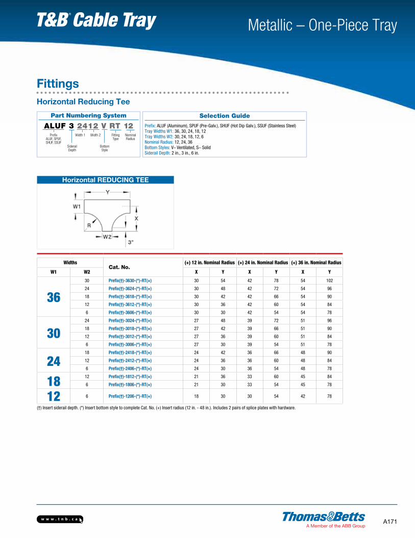
Part Numbering System
ALUF 3 2412 V RT 12Prefix
ALUF, SPUF,SHUF, SSUF
FittingType
NominalRadius
Width 1
SiderailDepth
Bottom Style
Width 2
FittingsHorizontal Reducing Tee
Horizontal REDUCING TEE
WidthsCat. No.
(+) 12 in. Nominal Radius (+) 24 in. Nominal Radius (+) 36 in. Nominal Radius
W1 W2 X Y X Y X Y
3630 Prefix(†)-3630-(*)-RT(+) 30 54 42 78 54 102
24 Prefix(†)-3624-(*)-RT(+) 30 48 42 72 54 96
18 Prefix(†)-3618-(*)-RT(+) 30 42 42 66 54 90
12 Prefix(†)-3612-(*)-RT(+) 30 36 42 60 54 84
6 Prefix(†)-3606-(*)-RT(+) 30 30 42 54 54 78
3024 Prefix(†)-3024-(*)-RT(+) 27 48 39 72 51 96
18 Prefix(†)-3018-(*)-RT(+) 27 42 39 66 51 90
12 Prefix(†)-3012-(*)-RT(+) 27 36 39 60 51 84
6 Prefix(†)-3006-(*)-RT(+) 27 30 39 54 51 78
2418 Prefix(†)-2418-(*)-RT(+) 24 42 36 66 48 90
12 Prefix(†)-2412-(*)-RT(+) 24 36 36 60 48 84
6 Prefix(†)-2406-(*)-RT(+) 24 30 36 54 48 78
18 12 Prefix(†)-1812-(*)-RT(+) 21 36 33 60 45 84
6 Prefix(†)-1806-(*)-RT(+) 21 30 33 54 45 78
12 6 Prefix(†)-1206-(*)-RT(+) 18 30 30 54 42 78
(†) Insert siderail depth. (*) Insert bottom style to complete Cat. No. (+) Insert radius (12 in. - 48 in.). Includes 2 pairs of splice plates with hardware.
Selection Guide
Prefix: ALUF (Aluminum), SPUF (Pre-Galv.), SHUF (Hot Dip Galv.), SSUF (Stainless Steel) Tray Widths W1: 36, 30, 24, 18, 12Tray Widths W2: 30, 24, 18, 12, 6Nominal Radius: 12, 24, 36 Bottom Styles: V– Ventilated, S– SolidSiderail Depth: 2 in., 3 in., 6 in.

w w w . t n b . c aA172
Metallic – One-Piece Tray T&B Cable Tray
Part Numbering System
ALUF 3 2430 V ET 12Prefix
ALUF, SPUF,SHUF, SSUF
FittingType
NominalRadius
Width 1
SiderailDepth
Bottom Style
Width 2
FittingsHorizontal Expanding Tee
Horizontal EXPANDING TEE — U-Style
WidthsCat. No.
(+) 12 in. Nominal Radius (+) 24 in. Nominal Radius (+) 36 in. Nominal Radius
W1 W2 X Y X Y X Y
30 36 Prefix(†)-3036-(*)-ET(+) 27 60 39 84 51 108
2430 Prefix(†)-2430-(*)-ET(+) 24 54 36 78 48 102
36 Prefix(†)-2436-(*)-ET(+) 24 60 36 84 48 108
1824 Prefix(†)-1824-(*)-ET(+) 21 48 33 72 45 96
30 Prefix(†)-1830-(*)-ET(+) 21 54 33 78 45 102
36 Prefix(†)-1836-(*)-ET(+) 21 60 33 84 45 108
1218 Prefix(†)-1218-(*)-ET(+) 18 42 30 66 42 90
24 Prefix(†)-1224-(*)-ET(+) 18 48 30 72 42 96
30 Prefix(†)-1230-(*)-ET(+) 18 54 30 78 42 102
36 Prefix(†)-1236-(*)-ET(+) 18 60 30 84 42 108
0612 Prefix(†)-0612-(*)-ET(+) 15 36 27 60 39 84
18 Prefix(†)-0618-(*)-ET(+) 15 42 27 66 39 90
24 Prefix(†)-0624-(*)-ET(+) 15 48 27 72 39 96
30 Prefix(†)-0630-(*)-ET(+) 15 54 27 78 39 102
36 Prefix(†)-0636-(*)-ET(+) 15 60 27 84 39 108
(†) Insert siderail depth. (*) Insert bottom style to complete Cat. No. (+) Insert radius (12 in. - 48 in.). Includes 2 pairs of splice plates with hardware.
Selection Guide
Prefix: SALUF (Aluminum), SPUF (Pre-Galv.), SHUF (Hot Dip Galv.), SSUF (Stainless Steel) Tray Widths W1: 30, 24, 18, 12, 6Tray Widths W2: 36, 30, 24, 18, 12 Nominal Radius: 12, 24, 36 Bottom Styles: V– Ventilated, S– SolidSiderail Depth: 2 in., 3 in., 6 in.
w w w . t n b . c a A173
Metallic – One-Piece Tray T&B Cable Tray
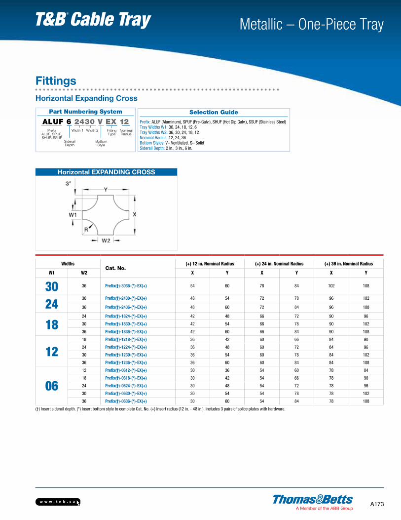
Part Numbering System
ALUF 6 2430 V EX 12Prefix
ALUF, SPUF,SHUF, SSUF
FittingType
NominalRadius
Width 1
SiderailDepth
Bottom Style
Width 2
FittingsHorizontal Expanding Cross
Selection Guide
Prefix: ALUF (Aluminum), SPUF (Pre-Galv.), SHUF (Hot Dip Galv.), SSUF (Stainless Steel)
Tray Widths W1: 30, 24, 18, 12, 6Tray Widths W2: 36, 30, 24, 18, 12Nominal Radius: 12, 24, 36 Bottom Styles: V– Ventilated, S– SolidSiderail Depth: 2 in., 3 in., 6 in.
Horizontal EXPANDING CROSS
WidthsCat. No.
(+) 12 in. Nominal Radius (+) 24 in. Nominal Radius (+) 36 in. Nominal Radius
W1 W2 X Y X Y X Y
30 36 Prefix(†)-3036-(*)-EX(+) 54 60 78 84 102 108
2430 Prefix(†)-2430-(*)-EX(+) 48 54 72 78 96 102
36 Prefix(†)-2436-(*)-EX(+) 48 60 72 84 96 108
1824 Prefix(†)-1824-(*)-EX(+) 42 48 66 72 90 96
30 Prefix(†)-1830-(*)-EX(+) 42 54 66 78 90 102
36 Prefix(†)-1836-(*)-EX(+) 42 60 66 84 90 108
1218 Prefix(†)-1218-(*)-EX(+) 36 42 60 66 84 90
24 Prefix(†)-1224-(*)-EX(+) 36 48 60 72 84 96
30 Prefix(†)-1230-(*)-EX(+) 36 54 60 78 84 102
36 Prefix(†)-1236-(*)-EX(+) 36 60 60 84 84 108
0612 Prefix(†)-0612-(*)-EX(+) 30 36 54 60 78 84
18 Prefix(†)-0618-(*)-EX(+) 30 42 54 66 78 90
24 Prefix(†)-0624-(*)-EX(+) 30 48 54 72 78 96
30 Prefix(†)-0630-(*)-EX(+) 30 54 54 78 78 102
36 Prefix(†)-0636-(*)-EX(+) 30 60 54 84 78 108
(†) Insert siderail depth. (*) Insert bottom style to complete Cat. No. (+) Insert radius (12 in. - 48 in.). Includes 3 pairs of splice plates with hardware.
w w w . t n b . c aA174
Metallic – One-Piece Tray T&B Cable Tray
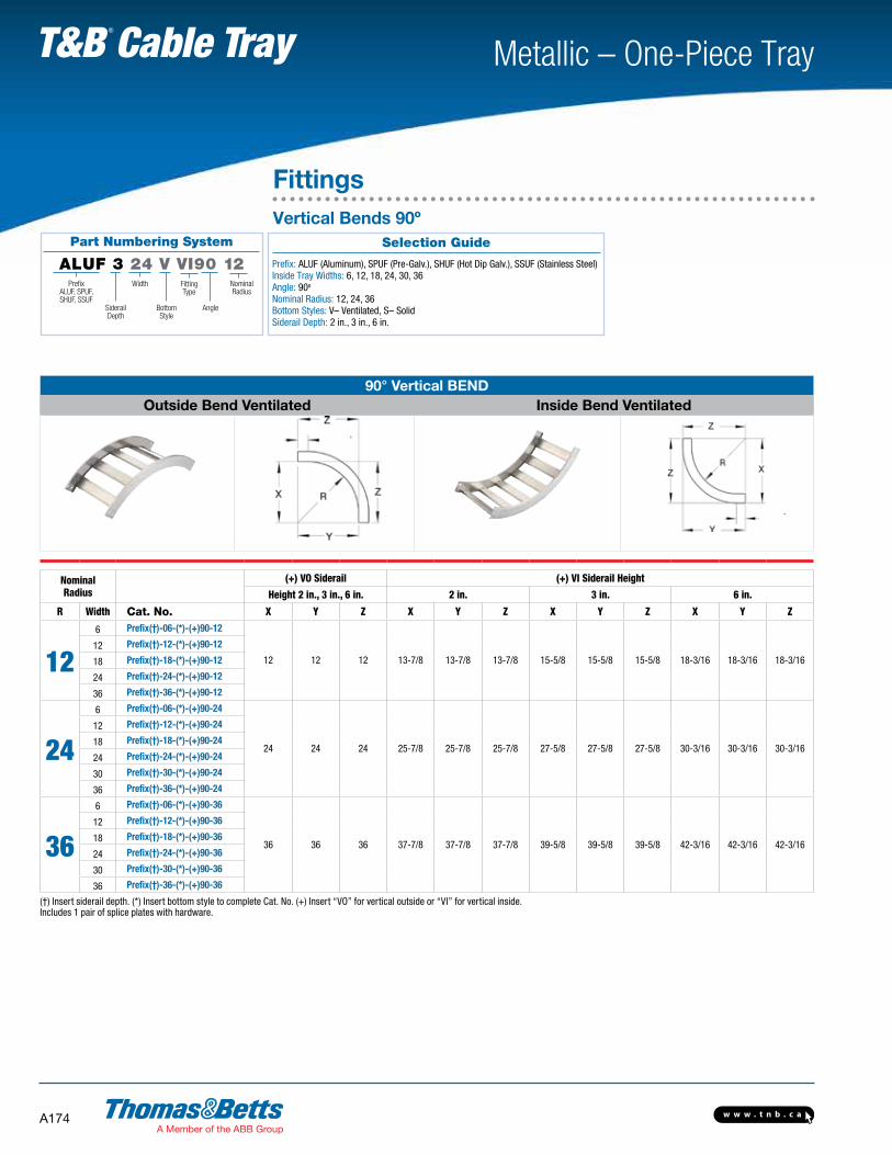
Part Numbering System
ALUF 3 24 V VI90 12Prefix
ALUF, SPUF,SHUF, SSUF
FittingType
NominalRadius
Width
SiderailDepth
Bottom Style
Angle
FittingsVertical Bends 90º
Selection Guide
Prefix: ALUF (Aluminum), SPUF (Pre-Galv.), SHUF (Hot Dip Galv.), SSUF (Stainless Steel) Inside Tray Widths: 6, 12, 18, 24, 30, 36Angle: 90o
Nominal Radius: 12, 24, 36Bottom Styles: V– Ventilated, S– SolidSiderail Depth: 2 in., 3 in., 6 in.
90° Vertical BEND Outside Bend Ventilated Inside Bend Ventilated
Nominal Radius
(+) VO Siderail (+) VI Siderail Height
Height 2 in., 3 in., 6 in. 2 in. 3 in. 6 in.
R Width Cat. No. X Y Z X Y Z X Y Z X Y Z
126 Prefix(†)-06-(*)-(+)90-12
12 12 12 13-7/8 13-7/8 13-7/8 15-5/8 15-5/8 15-5/8 18-3/16 18-3/16 18-3/16
12 Prefix(†)-12-(*)-(+)90-12
18 Prefix(†)-18-(*)-(+)90-12
24 Prefix(†)-24-(*)-(+)90-12
36 Prefix(†)-36-(*)-(+)90-12
24
6 Prefix(†)-06-(*)-(+)90-24
24 24 24 25-7/8 25-7/8 25-7/8 27-5/8 27-5/8 27-5/8 30-3/16 30-3/16 30-3/16
12 Prefix(†)-12-(*)-(+)90-24
18 Prefix(†)-18-(*)-(+)90-24
24 Prefix(†)-24-(*)-(+)90-24
30 Prefix(†)-30-(*)-(+)90-24
36 Prefix(†)-36-(*)-(+)90-24
36
6 Prefix(†)-06-(*)-(+)90-36
36 36 36 37-7/8 37-7/8 37-7/8 39-5/8 39-5/8 39-5/8 42-3/16 42-3/16 42-3/16
12 Prefix(†)-12-(*)-(+)90-36
18 Prefix(†)-18-(*)-(+)90-36
24 Prefix(†)-24-(*)-(+)90-36
30 Prefix(†)-30-(*)-(+)90-36
36 Prefix(†)-36-(*)-(+)90-36
(†) Insert siderail depth. (*) Insert bottom style to complete Cat. No. (+) Insert “VO” for vertical outside or “VI” for vertical inside. Includes 1 pair of splice plates with hardware.
w w w . t n b . c a A175
Metallic – One-Piece Tray T&B Cable Tray
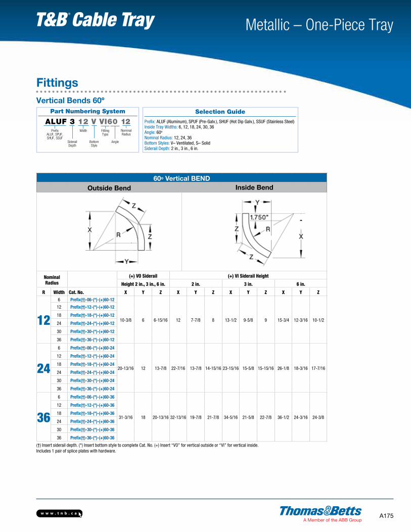
60o Vertical BENDOutside Bend Inside Bend
Nominal Radius
(+) VO Siderail (+) VI Siderail Height
Height 2 in., 3 in., 6 in. 2 in. 3 in. 6 in.
R Width Cat. No. X Y Z X Y Z X Y Z X Y Z
12
6 Prefix(†)-06-(*)-(+)60-12
10-3/8 6 6-15/16 12 7-7/8 8 13-1/2 9-5/8 9 15-3/4 12-3/16 10-1/2
12 Prefix(†)-12-(*)-(+)60-12
18 Prefix(†)-18-(*)-(+)60-12
24 Prefix(†)-24-(*)-(+)60-12
30 Prefix(†)-30-(*)-(+)60-12
36 Prefix(†)-36-(*)-(+)60-12
24
6 Prefix(†)-06-(*)-(+)60-24
20-13/16 12 13-7/8 22-7/16 13-7/8 14-15/16 23-15/16 15-5/8 15-15/16 26-1/8 18-3/16 17-7/16
12 Prefix(†)-12-(*)-(+)60-24
18 Prefix(†)-18-(*)-(+)60-24
24 Prefix(†)-24-(*)-(+)60-24
30 Prefix(†)-30-(*)-(+)60-24
36 Prefix(†)-36-(*)-(+)60-24
36
6 Prefix(†)-06-(*)-(+)60-36
31-3/16 18 20-13/16 32-13/16 19-7/8 21-7/8 34-5/16 21-5/8 22-7/8 36-1/2 24-3/16 24-3/8
12 Prefix(†)-12-(*)-(+)60-36
18 Prefix(†)-18-(*)-(+)60-36
24 Prefix(†)-24-(*)-(+)60-36
30 Prefix(†)-30-(*)-(+)60-36
36 Prefix(†)-36-(*)-(+)60-36
(†) Insert siderail depth. (*) Insert bottom style to complete Cat. No. (+) Insert “VO” for vertical outside or “VI” for vertical inside. Includes 1 pair of splice plates with hardware.
Part Numbering System
ALUF 3 12 V VI60 12Prefix
ALUF, SPUF,SHUF, SSUF
FittingType
NominalRadius
Width
SiderailDepth
Bottom Style
Angle
FittingsVertical Bends 60º
Selection Guide
Prefix: ALUF (Aluminum), SPUF (Pre-Galv.), SHUF (Hot Dip Galv.), SSUF (Stainless Steel) Inside Tray Widths: 6, 12, 18, 24, 30, 36Angle: 60o
Nominal Radius: 12, 24, 36Bottom Styles: V– Ventilated, S– SolidSiderail Depth: 2 in., 3 in., 6 in.
w w w . t n b . c aA176
Metallic – One-Piece Tray T&B Cable Tray
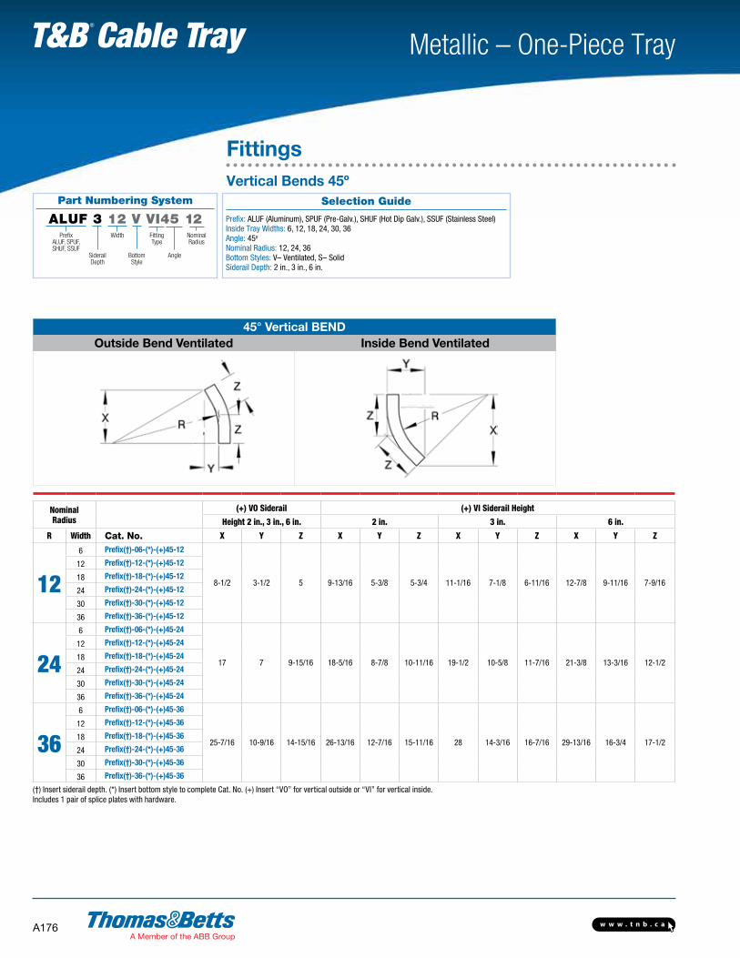
45° Vertical BEND Outside Bend Ventilated Inside Bend Ventilated
Nominal Radius
(+) VO Siderail (+) VI Siderail Height
Height 2 in., 3 in., 6 in. 2 in. 3 in. 6 in.
R Width Cat. No. X Y Z X Y Z X Y Z X Y Z
12
6 Prefix(†)-06-(*)-(+)45-12
8-1/2 3-1/2 5 9-13/16 5-3/8 5-3/4 11-1/16 7-1/8 6-11/16 12-7/8 9-11/16 7-9/16
12 Prefix(†)-12-(*)-(+)45-12
18 Prefix(†)-18-(*)-(+)45-12
24 Prefix(†)-24-(*)-(+)45-12
30 Prefix(†)-30-(*)-(+)45-12
36 Prefix(†)-36-(*)-(+)45-12
24
6 Prefix(†)-06-(*)-(+)45-24
17 7 9-15/16 18-5/16 8-7/8 10-11/16 19-1/2 10-5/8 11-7/16 21-3/8 13-3/16 12-1/2
12 Prefix(†)-12-(*)-(+)45-24
18 Prefix(†)-18-(*)-(+)45-24
24 Prefix(†)-24-(*)-(+)45-24
30 Prefix(†)-30-(*)-(+)45-24
36 Prefix(†)-36-(*)-(+)45-24
36
6 Prefix(†)-06-(*)-(+)45-36
25-7/16 10-9/16 14-15/16 26-13/16 12-7/16 15-11/16 28 14-3/16 16-7/16 29-13/16 16-3/4 17-1/2
12 Prefix(†)-12-(*)-(+)45-36
18 Prefix(†)-18-(*)-(+)45-36
24 Prefix(†)-24-(*)-(+)45-36
30 Prefix(†)-30-(*)-(+)45-36
36 Prefix(†)-36-(*)-(+)45-36
(†) Insert siderail depth. (*) Insert bottom style to complete Cat. No. (+) Insert “VO” for vertical outside or “VI” for vertical inside.Includes 1 pair of splice plates with hardware.
FittingsVertical Bends 45º
Selection Guide
Prefix: ALUF (Aluminum), SPUF (Pre-Galv.), SHUF (Hot Dip Galv.), SSUF (Stainless Steel) Inside Tray Widths: 6, 12, 18, 24, 30, 36Angle: 45o
Nominal Radius: 12, 24, 36Bottom Styles: V– Ventilated, S– SolidSiderail Depth: 2 in., 3 in., 6 in.
Part Numbering System
ALUF 3 12 V VI45 12Prefix
ALUF, SPUF,SHUF, SSUF
FittingType
NominalRadius
Width
SiderailDepth
Bottom Style
Angle

w w w . t n b . c a A177
Metallic – One-Piece Tray T&B Cable Tray
30° Vertical BEND Outside Bend Ventilated Inside Bend Ventilated
Nominal Radius
(+) VO Siderail (+) VI Siderail Height
Height 2 in., 3 in., 6 in. 2 in. 3 in. 6 in.
R Width Cat. No. X Y Z X Y Z X Y Z X Y Z
12
6 Prefix(†)-06-(*)-(+)30-12
6 1-5/8 3-3/16 6-15/16 3-1/2 3-11/16 7-13/16 5-1/4 4-3/16 9-1/8 7-13/16 4-7/8
12 Prefix(†)-12-(*)-(+)30-12
18 Prefix(†)-18-(*)-(+)30-12
24 Prefix(†)-24-(*)-(+)30-12
30 Prefix(†)-30-(*)-(+)30-12
36 Prefix(†)-36-(*)-(+)30-12
24
6 Prefix(†)-06-(*)-(+)30-24
12 3-3/16 6-7/16 12-15/16 5-1/16 6-15/16 13-13/16 6-13/16 7-3/8 15-1/8 9-3/8 8-1/16
12 Prefix(†)-12-(*)-(+)30-24
18 Prefix(†)-18-(*)-(+)30-24
24 Prefix(†)-24-(*)-(+)30-24
30 Prefix(†)-30-(*)-(+)30-24
36 Prefix(†)-36-(*)-(+)30-24
36
6 Prefix(†)-06-(*)-(+)30-36
18 4-13/16 9-5/8 18-15/16 6-11/16 10-1/8 19-13/16 8-7/16 10-5/8 21-1/8 11 11-5/16
12 Prefix(†)-12-(*)-(+)30-36
18 Prefix(†)-18-(*)-(+)30-36
24 Prefix(†)-24-(*)-(+)30-36
30 Prefix(†)-30-(*)-(+)30-36
36 Prefix(†)-36-(*)-(+)30-36
(†) Insert siderail depth. (*) Insert bottom style to complete Cat. No. (+) Insert “VO” for vertical outside or “VI” for vertical inside.Includes 1 pair of splice plates with hardware.
Selection Guide
Prefix: ALUF (Aluminum), SPUF (Pre-Galv.), SHUF (Hot Dip Galv.), SSUF (Stainless Steel) Inside Tray Widths: 6, 12, 18, 24, 30, 36Angle: 30o
Nominal Radius: 12, 24, 36Bottom Styles: V– Ventilated, S– SolidSiderail Depth: 2 in., 3 in., 6 in.
Part Numbering System
ALUF 3 06 V VI30 12Prefix
ALUF, SPUF,SHUF, SSUF
FittingType
NominalRadius
Width
SiderailDepth
Bottom Style
Angle
FittingsVertical Bends 30º
w w w . t n b . c aA178
Metallic – One-Piece Tray T&B Cable Tray
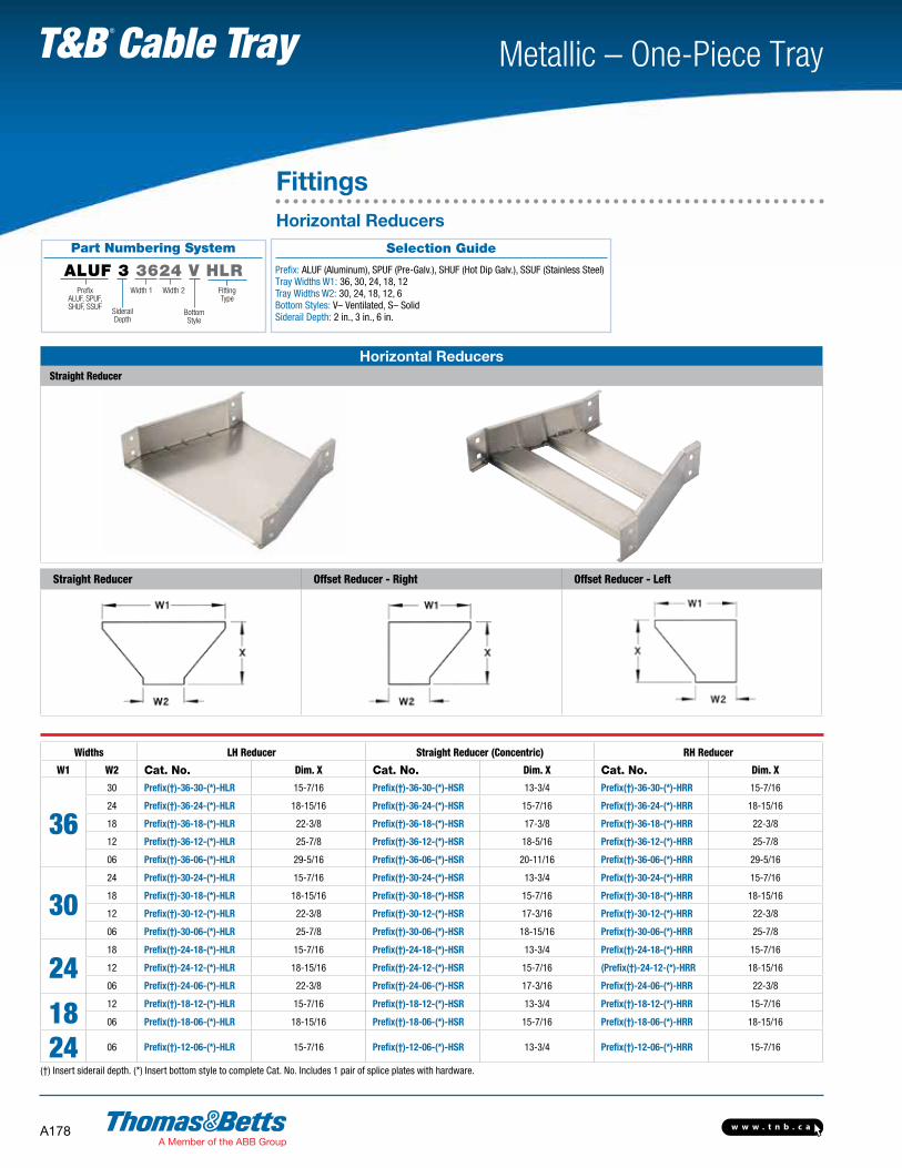
Horizontal ReducersStraight Reducer
Straight Reducer Offset Reducer - Right Offset Reducer - Left
Widths LH Reducer Straight Reducer (Concentric) RH Reducer
W1 W2 Cat. No. Dim. X Cat. No. Dim. X Cat. No. Dim. X
3630 Prefix(†)-36-30-(*)-HLR 15-7/16 Prefix(†)-36-30-(*)-HSR 13-3/4 Prefix(†)-36-30-(*)-HRR 15-7/16
24 Prefix(†)-36-24-(*)-HLR 18-15/16 Prefix(†)-36-24-(*)-HSR 15-7/16 Prefix(†)-36-24-(*)-HRR 18-15/16
18 Prefix(†)-36-18-(*)-HLR 22-3/8 Prefix(†)-36-18-(*)-HSR 17-3/8 Prefix(†)-36-18-(*)-HRR 22-3/8
12 Prefix(†)-36-12-(*)-HLR 25-7/8 Prefix(†)-36-12-(*)-HSR 18-5/16 Prefix(†)-36-12-(*)-HRR 25-7/8
06 Prefix(†)-36-06-(*)-HLR 29-5/16 Prefix(†)-36-06-(*)-HSR 20-11/16 Prefix(†)-36-06-(*)-HRR 29-5/16
3024 Prefix(†)-30-24-(*)-HLR 15-7/16 Prefix(†)-30-24-(*)-HSR 13-3/4 Prefix(†)-30-24-(*)-HRR 15-7/16
18 Prefix(†)-30-18-(*)-HLR 18-15/16 Prefix(†)-30-18-(*)-HSR 15-7/16 Prefix(†)-30-18-(*)-HRR 18-15/16
12 Prefix(†)-30-12-(*)-HLR 22-3/8 Prefix(†)-30-12-(*)-HSR 17-3/16 Prefix(†)-30-12-(*)-HRR 22-3/8
06 Prefix(†)-30-06-(*)-HLR 25-7/8 Prefix(†)-30-06-(*)-HSR 18-15/16 Prefix(†)-30-06-(*)-HRR 25-7/8
2418 Prefix(†)-24-18-(*)-HLR 15-7/16 Prefix(†)-24-18-(*)-HSR 13-3/4 Prefix(†)-24-18-(*)-HRR 15-7/16
12 Prefix(†)-24-12-(*)-HLR 18-15/16 Prefix(†)-24-12-(*)-HSR 15-7/16 (Prefix(†)-24-12-(*)-HRR 18-15/16
06 Prefix(†)-24-06-(*)-HLR 22-3/8 Prefix(†)-24-06-(*)-HSR 17-3/16 Prefix(†)-24-06-(*)-HRR 22-3/8
18 12 Prefix(†)-18-12-(*)-HLR 15-7/16 Prefix(†)-18-12-(*)-HSR 13-3/4 Prefix(†)-18-12-(*)-HRR 15-7/16
06 Prefix(†)-18-06-(*)-HLR 18-15/16 Prefix(†)-18-06-(*)-HSR 15-7/16 Prefix(†)-18-06-(*)-HRR 18-15/16
24 06 Prefix(†)-12-06-(*)-HLR 15-7/16 Prefix(†)-12-06-(*)-HSR 13-3/4 Prefix(†)-12-06-(*)-HRR 15-7/16
(†) Insert siderail depth. (*) Insert bottom style to complete Cat. No. Includes 1 pair of splice plates with hardware.
FittingsHorizontal Reducers
Selection Guide
Prefix: ALUF (Aluminum), SPUF (Pre-Galv.), SHUF (Hot Dip Galv.), SSUF (Stainless Steel) Tray Widths W1: 36, 30, 24, 18, 12 Tray Widths W2: 30, 24, 18, 12, 6Bottom Styles: V– Ventilated, S– SolidSiderail Depth: 2 in., 3 in., 6 in.
Part Numbering System
ALUF 3 3624 V HLRPrefix
ALUF, SPUF,SHUF, SSUF
FittingType
Width 1
SiderailDepth
Bottom Style
Width 2
w w w . t n b . c a A179
Metallic – One-Piece Tray T&B Cable Tray
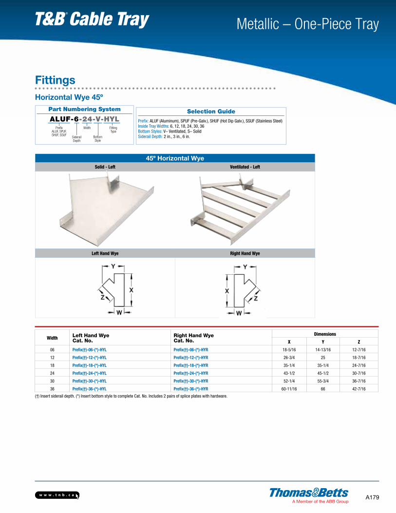
45º Horizontal WyeSolid - Left Ventilated - Left
Left Hand Wye Right Hand Wye
Width Left Hand WyeCat. No.
Right Hand WyeCat. No.
Dimensions
X Y Z
06 Prefix(†)-06-(*)-HYL Prefix(†)-06-(*)-HYR 18-5/16 14-13/16 12-7/16
12 Prefix(†)-12-(*)-HYL Prefix(†)-12-(*)-HYR 26-3/4 25 18-7/16
18 Prefix(†)-18-(*)-HYL Prefix(†)-18-(*)-HYR 35-1/4 35-1/4 24-7/16
24 Prefix(†)-24-(*)-HYL Prefix(†)-24-(*)-HYR 43-1/2 45-1/2 30-7/16
30 Prefix(†)-30-(*)-HYL Prefix(†)-30-(*)-HYR 52-1/4 55-3/4 36-7/16
36 Prefix(†)-36-(*)-HYL Prefix(†)-36-(*)-HYR 60-11/16 66 42-7/16
(†) Insert siderail depth. (*) Insert bottom style to complete Cat. No. Includes 2 pairs of splice plates with hardware.
FittingsHorizontal Wye 45º
Part Numbering System
ALUF-6-24-V-HYLWidth
Bottom Style
SiderailDepth
PrefixALUF, SPUF,SHUF, SSUF
Fitting Type
Selection Guide
Prefix: ALUF (Aluminum), SPUF (Pre-Galv.), SHUF (Hot Dip Galv.), SSUF (Stainless Steel) Inside Tray Widths: 6, 12, 18, 24, 30, 36 Bottom Styles: V– Ventilated, S– SolidSiderail Depth: 2 in., 3 in., 6 in.

w w w . t n b . c aA180
Metallic – One-Piece Tray T&B Cable Tray
Part Numbering System
ALUF 6 24 V VTD 12Width
Bottom Style
SiderailDepth
PrefixALUF, SPUF,SHUF, SSUF
Fitting Type
Nominal Radius
FittingsVertical Tee Up / Down
Selection Guide
Prefix: ALUF (Aluminum), SPUF (Pre-Galv.), SHUF (Hot Dip Galv.), SSUF (Stainless Steel) Inside Tray Widths: 6, 12, 18, 24, 30, 36 Nominal Radius: 12, 24, 36Bottom Styles: V– Ventilated, S– SolidSiderail Depth: 2 in., 3 in., 6 in.
Vertical TEE Up / DownSolid Ventilated
Down Up
Nominal Radius Vertical Tee Up Vertical Tee Down
Siderail Height “H”
2 in. 3 in. 6 in.
R Width Cat. No. Cat. No. X Y X Y X Y
12
6 Prefix(†)-06-(*)-VTU12 Prefix-06-(*)-VTD12
12-15/16 25-7/8 13-13/16 27-5/8 15-1/8 30-3/16
12 Prefix(†)-12-(*)-VTU12 Prefix-12-(*)-VTD12
18 Prefix(†)-18-(*)-VTU12 Prefix-18-(*)-VTD12
24 Prefix(†)-24-(*)-VTU12 Prefix-24-(*)-VTD12
30 Prefix(†)-30-(*)-VTU12 Prefix-30-(*)-VTD12
36 Prefix(†)-36-(*)-VTU12 Prefix-36-(*)-VTD12
24
6 Prefix(†)-06-(*)-VTU24 Prefix-06-(*)-VTD24
24-15/16 49-7/8 25-13/16 51-5/8 27-1/8 54-3/16
12 Prefix(†)-12-(*)-VTU24 Prefix-12-(*)-VTD24
18 Prefix(†)-18-(*)-VTU24 Prefix-18-(*)-VTD24
24 Prefix(†)-24-(*)-VTU24 Prefix-24-(*)-VTD24
30 Prefix(†)-30-(*)-VTU24 Prefix-30-(*)-VTD24
36 Prefix(†)-36-(*)-VTU24 Prefix-36-(*)-VTD24
36
6 Prefix(†)-06-(*)-VTU36 Prefix-06-(*)-VTD36
36-15/16 73-7/8 37-13/16 75-5/8 39-1/8 78-3/16
12 Prefix(†)-12-(*)-VTU36 Prefix-12-(*)-VTD36
18 Prefix(†)-18-(*)-VTU36 Prefix-18-(*)-VTD36
24 Prefix(†)-24-(*)-VTU36 Prefix-24-(*)-VTD36
30 Prefix(†)-30-(*)-VTU36 Prefix-30-(*)-VTD36
36 Prefix(†)-36-(*)-VTU36 Prefix-36-(*)-VTD36
(†) Insert siderail depth. (*) Insert bottom style to complete Cat. No. Includes 2 pairs of splice plates with hardware.
w w w . t n b . c a A181
Metallic – One-Piece Tray T&B Cable Tray
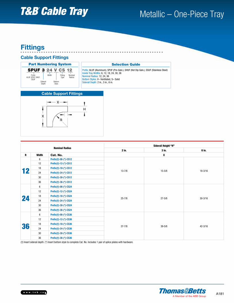
Part Numbering System
SPUF 3 24 V CS 12Width
Bottom Style
SiderailDepth
PrefixALUF, SPUF, SHUF,
SSUF
Nominal Radius
Fitting Type
FittingsCable Support Fittings
Selection Guide
Prefix: ALUF (Aluminum), SPUF (Pre-Galv.), SHUF (Hot Dip Galv.), SSUF (Stainless Steel) Inside Tray Widths: 6, 12, 18, 24, 30, 36 Nominal Radius: 12, 24, 36Bottom Styles: V– Ventilated, S– SolidSiderail Depth: 2 in., 3 in., 6 in.
Cable Support Fittings
Nominal RadiusSiderail Height “H”
2 in. 3 in. 6 in.
R Width Cat. No. X
12
6 Prefix(†)-06-(*)-CS12
13-7/8 15-5/8 18-3/16
12 Prefix(†)-12-(*)-CS12
18 Prefix(†)-18-(*)-CS12
24 Prefix(†)-24-(*)-CS12
30 Prefix(†)-30-(*)-CS12
36 Prefix(†)-36-(*)-CS12
24
6 Prefix(†)-06-(*)-CS24
25-7/8 27-5/8 30-3/16
12 Prefix(†)-12-(*)-CS24
18 Prefix(†)-18-(*)-CS24
24 Prefix(†)-24-(*)-CS24
30 Prefix(†)-30-(*)-CS24
36 Prefix(†)-36-(*)-CS24
36
6 Prefix(†)-06-(*)-CS36
37-7/8 39-5/8 42-3/16
12 Prefix(†)-12-(*)-CS36
18 Prefix(†)-18-(*)-CS36
24 Prefix(†)-24-(*)-CS36
30 Prefix(†)-30-(*)-CS36
36 Prefix(†)-36-(*)-CS36
(†) Insert siderail depth. (*) Insert bottom style to complete Cat. No. Includes 1 pair of splice plates with hardware.

w w w . t n b . c aA182
Metallic – One-Piece Tray T&B Cable Tray
Straight Cover Number Selection
(ALUW12)SNC-3
Material Width Bottom Type Length
ALUW • AluminumSPW • Pre-Galvanized
SHW • Hot Dip Galvanized after fabrication SSW • Stainless Steel 316
06 • (6 in.)12 • (12 in.)18 • (18 in.)24 • (24 in.)30 • (30 in.)36 • (36 in.)
SNC • Solid Non-Flanged CoverSFC • Solid Flanged CoverVFC • Ventilated Flanged CoverPFC • Peaked Flanged CoverPVC • Peaked Ventilated Cover
3 •(3 meters)
* For SHW covers, maximum lengths are 72 in. and 1500 mm.
Fitting Cover Number Selection
(ALUW12)SNCHB9024
Material Width Cover Type Fitting Type Degree* Radius
ALUW • AluminumSPW • Pre-Galvanized SHW • Hot Dip Galvanized after fabrication SSW • Stainless Steel 316
06 • (6 in.)12 • (12 in.)18 • (18 in.)24 • (24 in.)30 • (30 in.)36 • (36 in.)
SNC • Solid Non-Flanged CoverSFC • Solid Flanged CoverVFC • Ventilated Flanged Cover
HB • Horizontal BendHT • Horizontal Tee HX • Horizontal CrossVI • Vertical Inside Bend VTU • Vertical Tee DownHYR • Horizontal Wye Right HYL • Horizontal Wye Left
30 • (30°)45 • (45°)60 • (60°)90 • (90°)
12 • (12 in.)24 • (24 in.)36 • (36 in.)
Note: Cover mounting hardware sold separately.* Required for HB & VI only
Prefix
Covers
Prefix

w w w . t n b . c a A183
Metallic – One-Piece Tray T&B Cable Tray
Fitting Cover Number Selection (cont’d)
(ALUW1812)SNCRT12
Material Width 1 Width 2 Cover Type Fitting Type Radius*
ALUW • AluminumSPW • Pre-Galvanized SHW • Hot Dip Galvanized after fabrication SSW • Stainless Steel 316
06 • (6 in.)12 • (12 in.)18 • (18 in.)24 • (24 in.)30 • (30 in.)36 • (36 in.)
06 • (6 in.)12 • (12 in.)18 • (18 in.)24 • (24 in.)30 • (30 in.)36 • (36 in.)
SNC • Solid Non-Flanged CoverSFC • Solid Flanged CoverVFC • Ventilated Flanged Cover
RT • Horizontal Reduce TeeET • Horizontal Expand Tee EX • Horizontal Expand EX • Tee & Reduce Cross HSR • Horizontal Straight Reducer HLR • Horizontal Left Reducer HRR • Horizontal Right Reducer
12 • (12 in.)24 • (24 in.)36 • (36 in.)
* Radius not required for HSR, HLR, HRR
Fitting Cover Number Selection
(ALUW312)SNCVO9024
Material Siderail Height Width Cover Type Fitting Type Degree* Radius
ALUW • AluminumSPW • Pre-Galvanized SHW • Hot Dip Galvanized after fabrication SSW • Stainless Steel 316
2 • (2 in.)3 • (3-5/8 in.)6 • (6 in.)
06 • (6 in.)12 • (12 in.)18 • (18 in.)24 • (24 in.)30 • (30 in.)36 • (36 in.)
SNC • Solid Non-Flanged CoverSFC • Solid Flanged CoverVFC • Ventilated Flanged Cover
VO • Vertical Outside Bend VTD • Vertical Tee Down CS • Cable Support
30 • (30o)45 • (45o)60 • (60o)90 • (90o)
12 • (12 in.)24 • (24 in.)36 • (36 in.)
Note: Cover mounting hardware sold separately.* Required for VO only
Covers
Prefix
Prefix
w w w . t n b . c aA184
Metallic – One-Piece Tray T&B Cable Tray
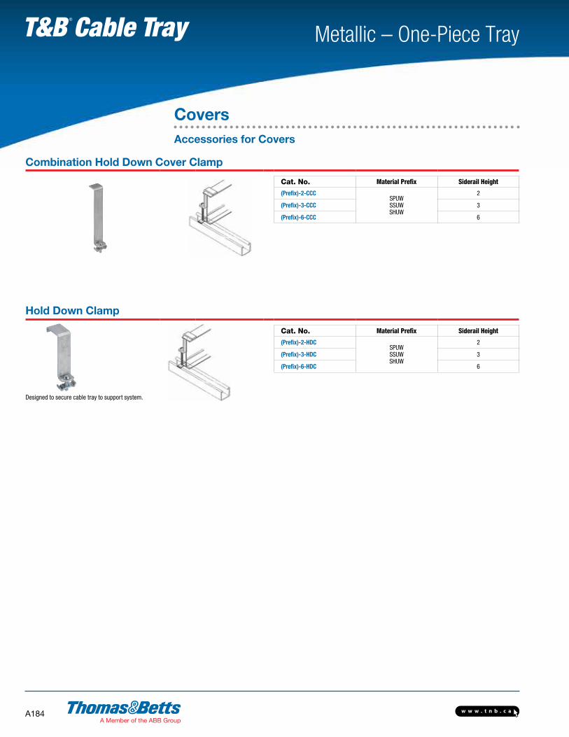
CoversAccessories for Covers
Combination Hold Down Cover Clamp
Cat. No. Material Prefix Siderail Height
(Prefix)-2-CCCSPUWSSUWSHUW
2
(Prefix)-3-CCC 3
(Prefix)-6-CCC 6
Hold Down Clamp
Cat. No. Material Prefix Siderail Height
(Prefix)-2-HDCSPUWSSUWSHUW
2
(Prefix)-3-HDC 3
(Prefix)-6-HDC 6
Designed to secure cable tray to support system.

w w w . t n b . c a A185
Metallic – One-Piece Tray T&B Cable Tray
CoversAccessories for Covers
Cover Clamp
Cat. No. Material Prefix Siderail Height
(Prefix)-2-SCC SPUWSSUW 2
(Prefix)-3-SCC SPWSSW
3
(Prefix)-6-SCC 6
Rigid indoor cover clamp for flat and flanged covers.
Heavy-Duty Cover Clamp
Cat. No. Material Prefix Siderail Height Width of Tray (in.)
(Prefix)-2-**-HCC
ALUWSHUWSPUWSSUW
2 61218243036
(Prefix)-3-**-HCC ALUWSHW SPWSSW
3
(Prefix)-6-**-HCC 6
** Insert Width of Tray
w w w . t n b . c aA186
Metallic – One-Piece Tray T&B Cable Tray
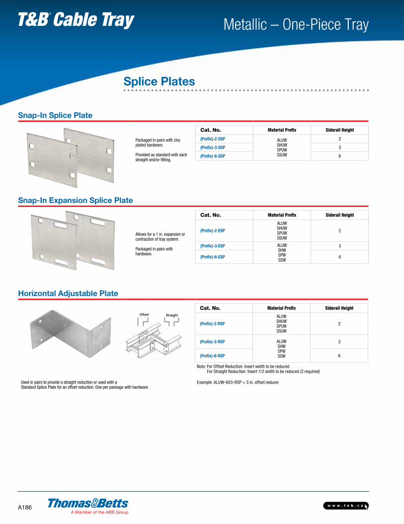
Splice Plates
Snap-In Splice Plate
Packaged in pairs with zinc plated hardware.
Provided as standard with each straight and/or fitting.
Cat. No. Material Prefix Siderail Height
(Prefix)-2-SSP ALUW SHUW SPUW SSUW
2
(Prefix)-3-SSP 3
(Prefix)-6-SSP 6
Snap-In Expansion Splice Plate
Allows for a 1 in. expansion or contraction of tray system.
Packaged in pairs with hardware.
Cat. No. Material Prefix Siderail Height
(Prefix)-2-ESP
ALUW SHUW SPUW SSUW
2
(Prefix)-3-ESP ALUW SHW SPW SSW
3
(Prefix)-6-ESP 6
Horizontal Adjustable Plate
Cat. No. Material Prefix Siderail Height
(Prefix)-2-RSP
ALUW SHUW SPUW SSUW
2
(Prefix)-3-RSP ALUW SHW SPW SSW
3
(Prefix)-6-RSP 6
Note: For Offset Reduction: Insert width to be reduced. For Straight Reduction: Insert 1/2 width to be reduced (2 required)
Example: ALUW-603-RSP = 3 in. offset reducerUsed in pairs to provide a straight reduction or used with a Standard Splice Plate for an offset reduction. One per package with hardware.
Offset Straight

w w w . t n b . c a A187
Metallic – One-Piece Tray T&B Cable Tray
Barrier Strips
Horizontal Barrier Strips
Cat. No. Material Prefix Height (in.) Length (in.)
(Prefix)-2-SB-3
ALUWSPUWSHUW*SSUW
2
3 m(Prefix)-3-SB-3 3
(Prefix)-6-SB-3 6
(Prefix)-2-SBH-72 2
72 in.(Prefix)-3-SBH-72 3
(Prefix)-6-SBH-72 6
NOTE: 72 in. barriers provided with 3 SPW10SCR, 3 m barriers provided with 6 SPW10SCR *Available in 1500 mm only.
Barrier Strips provide a method of separating cables in tray and trough systems. Easily installed using supplied hardware or Barrier Strip Clamps (sold separately). 72 in. barriers are flexible for use with horizontal fittings.
Vertical Barriers Strips
Inside Bend Cat. No.
Outside Bend Cat. No. Material Prefix Height (in.) Angle Radius
(Prefix)-2-VIB-(*)-(**) Prefix-2-VOB-(*)-(**) ALUWSPUWSHUWSSUW
2 90603045
122436
(Prefix)-3-VIB-(*)-(**) Prefix-3-VOB-(*)-(**) 3
(Prefix)-6-VIB-(*)-(**) Prefix-6-VOB-(*)-(**) 6
(*) Insert Angle (**) Insert Radius. *Available in 1500 mm only.
Preformed to fit all standard steel vertical bends. Provided with hardware
Barrier Strip Splice
Cat. No. Material
SPW-BSC Zinc Plated Steel
SSW-BSC Stainless Steel 316
Barrier strip clamps mount barrier strips to ladder rungs and ventilated bottoms. Complete mounting hardware supplied.
SBH
SB
T&B aluminum cable tray is composed of two distinct systems H-Style and U-Style. These systems are interchangeable.
w w w . t n b . c aA188
Metallic – One-Piece Tray T&B Cable Tray
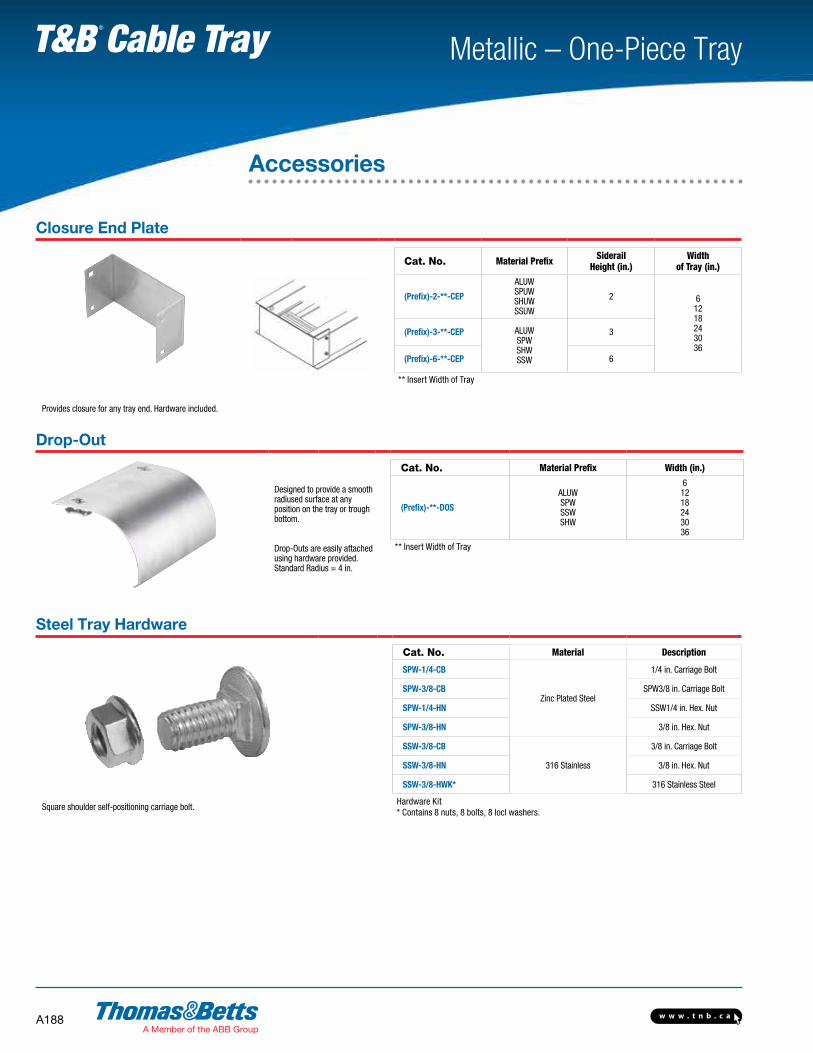
Closure End Plate
Cat. No. Material Prefix Siderail Height (in.)
Width of Tray (in.)
(Prefix)-2-**-CEP
ALUWSPUWSHUWSSUW
2 61218243036
(Prefix)-3-**-CEP ALUWSPWSHWSSW
3
(Prefix)-6-**-CEP 6
** Insert Width of Tray
Provides closure for any tray end. Hardware included.
Drop-Out
Designed to provide a smooth radiused surface at any position on the tray or trough bottom.
Drop-Outs are easily attached using hardware provided.Standard Radius = 4 in.
Cat. No. Material Prefix Width (in.)
(Prefix)-**-DOS
ALUWSPWSSWSHW
61218243036
** Insert Width of Tray
Steel Tray Hardware
Cat. No. Material Description
SPW-1/4-CB
Zinc Plated Steel
1/4 in. Carriage Bolt
SPW-3/8-CB SPW3/8 in. Carriage Bolt
SPW-1/4-HN SSW1/4 in. Hex. Nut
SPW-3/8-HN 3/8 in. Hex. Nut
SSW-3/8-CB
316 Stainless
3/8 in. Carriage Bolt
SSW-3/8-HN 3/8 in. Hex. Nut
SSW-3/8-HWK* 316 Stainless Steel
Square shoulder self-positioning carriage bolt.Hardware Kit* Contains 8 nuts, 8 bolts, 8 locl washers.
Accessories
w w w . t n b . c a A189
Metallic – One-Piece Tray T&B Cable Tray
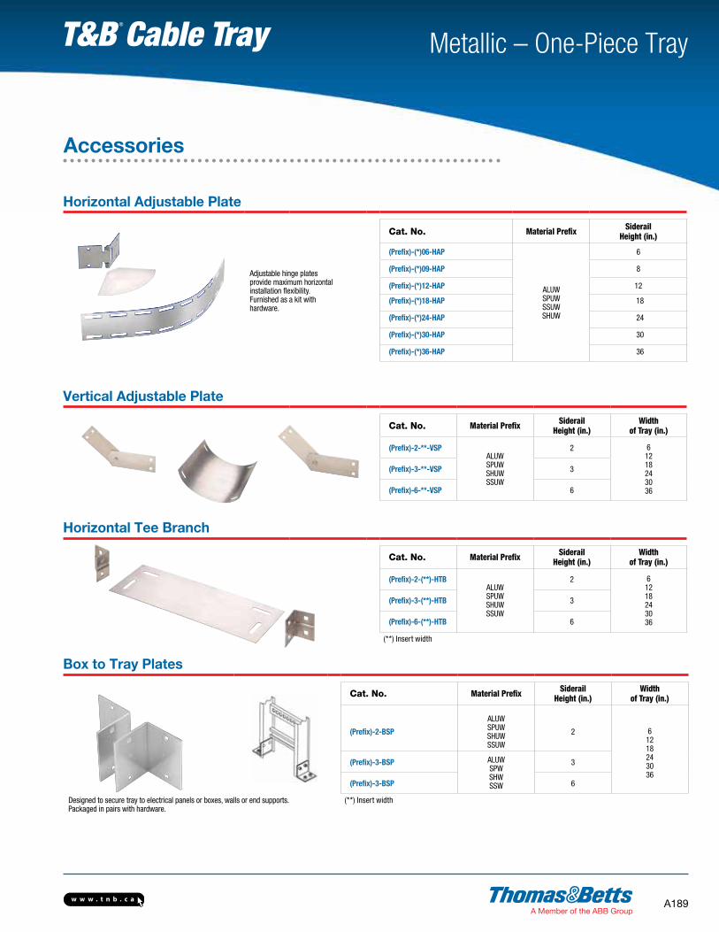
Horizontal Adjustable Plate
Adjustable hinge plates provide maximum horizontal installation flexibility.Furnished as a kit with hardware.
Cat. No. Material Prefix Siderail Height (in.)
(Prefix)-(*)06-HAP
ALUWSPUWSSUWSHUW
6
(Prefix)-(*)09-HAP 8
(Prefix)-(*)12-HAP 12
(Prefix)-(*)18-HAP 18
(Prefix)-(*)24-HAP 24
(Prefix)-(*)30-HAP 30
(Prefix)-(*)36-HAP 36
Vertical Adjustable Plate
Cat. No. Material Prefix Siderail Height (in.)
Width of Tray (in.)
(Prefix)-2-**-VSPALUWSPUWSHUWSSUW
2 61218243036
(Prefix)-3-**-VSP 3
(Prefix)-6-**-VSP 6
Horizontal Tee Branch
Cat. No. Material Prefix Siderail Height (in.)
Width of Tray (in.)
(Prefix)-2-(**)-HTBALUWSPUWSHUWSSUW
2 61218243036
(Prefix)-3-(**)-HTB 3
(Prefix)-6-(**)-HTB 6
(**) Insert width
Box to Tray Plates
Cat. No. Material Prefix Siderail Height (in.)
Width of Tray (in.)
(Prefix)-2-BSP
ALUWSPUWSHUWSSUW
2 61218243036
(Prefix)-3-BSP ALUWSPWSHWSSW
3
(Prefix)-3-BSP 6
Designed to secure tray to electrical panels or boxes, walls or end supports. Packaged in pairs with hardware.
(**) Insert width
Accessories