Metallic and semi-metallic gaskets Index
42
Metallic and semi-metallic gaskets Index Gaskets and seals HA-001 page 913 20080301 A Index and product compare General information page Introduction 914 Gaskets, assembling 916 Product information Camprofile gaskets page Standard profile shapes 917 Other profile shapes 918 Dimension table for camprofile gaskets page For ASME B16.5 Raised Face flanges RF; Camprofile gaskets 919 For ASME B16.5 Slip-On flanges RF; Camprofile gaskets 920 For ASME B16.47 series A flanges RF; Camprofile gaskets 921 For ASME B16.5 Tongue/Groove flanges Tongue/Groove; Camprofile gaskets 922 For ASME B16.5 Male/Female flanges Male/Female; Camprofile gaskets 923 For DIN Raised Face flanges RF; Camprofile gaskets 924 For DIN Tongue/Groove flanges Tongue/Groove; Camprofile gaskets 925 For DIN Male/Female flanges Male/Female; Camprofile gaskets 926 Spiral wound gaskets page Standard profile shapes 927 Other profile shapes 928 Dimension table for spiral wound gaskets page For ASME B16.5 Raised Face flanges RF; Spiral wound gaskets; Pressure rating 150 lbs - 1500 lbs 929 RF; Spiral wound gaskets; Pressure rating 2500 lbs 930 For ASME B16.47 series A flanges RF; Spiral wound gaskets 931 For ASME B16.47 series B flanges RF; Spiral wound gaskets 932 For ASME B16.5 Male/Female flanges Male/Female; Spiral wound gaskets 933 For ASME B16.5 Tongue/Groove flanges Tongue/Groove; Spiral wound gaskets 934 For DIN Raised Face flanges RF; Spiral wound gaskets 935 For DIN 2513 Male/Female flanges Male/Female; Spiral wound gaskets 936 For DIN 2512 Tongue/Groove flanges Tongue/Groove; Spiral wound gaskets 937 Ring Joint gaskets page For standard ASME, API piping systems 938 Selection table for Ring Joint gaskets, types R or RX page For ASME B16.5 and BS 1560 flanges Ring Joint gaskets 939 Selection table for Ring Joint gaskets, type BX page For API spec. 6A, type 6BX flanges Ring Joint gaskets 940 Selection table for Ring Joint gaskets, types R or RX page For ASME B16.47 series A flanges Ring Joint gaskets 941 Selection table for Ring Joint gaskets, type R or RX page For API spec. 6A, model 6B flanges Ring Joint gaskets 942 Selection table for Ring Joint gaskets, type RX page For segmented API spec. 6A flanges Ring Joint gaskets 943 Product information (continued) Dimension table for Ring Joint gaskets and grooves, type R page As per ASME B16.20, API spec. 6A and ISO 7483 Ring Joint gaskets 944 As per ASME B16.20, API spec. 6A and ISO 7483 (continued) Ring Joint gaskets 945 Dimension table for Ring Joint gaskets and grooves, type RX page As per ASME B16.20, API spec. 6A Ring Joint gaskets 946 Dimension table for Ring Joint gaskets and grooves, type BX page As per ASME B16.20 and API spec. 6A Ring Joint gaskets 947 Welded membranes page Welded membranes 948 Metal jacketed gaskets page Series 2092 949 Corrugated rings page Series 2095/Series 2096 950 Metallic sealing rings page Flat, insert, lens, Delta and O-sealing rings Overview of metallic sealing rings 951 Dimension table for flat and convex sealing rings page Flat and convex; sealing rings 952 Dimension table for metal insert rings page For DIN 2512 flanges Metal insert rings 953 For ASME B16.5 flanges Metal rings 954
Transcript of Metallic and semi-metallic gaskets Index

Metallic and semi-metallic gasketsIndex
Gaskets and seals HA-001 page 913
2008
0301
A Index and product compare
General informationpage
Introduction 914Gaskets, assembling 916
Product informationCamprofile gaskets page
Standard profile shapes 917Other profile shapes 918
Dimension table for camprofile gaskets pageFor ASME B16.5 Raised Face flanges
RF; Camprofile gaskets 919For ASME B16.5 Slip-On flanges
RF; Camprofile gaskets 920For ASME B16.47 series A flanges
RF; Camprofile gaskets 921For ASME B16.5 Tongue/Groove flanges
Tongue/Groove; Camprofile gaskets 922For ASME B16.5 Male/Female flanges
Male/Female; Camprofile gaskets 923For DIN Raised Face flanges
RF; Camprofile gaskets 924For DIN Tongue/Groove flanges
Tongue/Groove; Camprofile gaskets 925For DIN Male/Female flanges
Male/Female; Camprofile gaskets 926
Spiral wound gaskets pageStandard profile shapes 927Other profile shapes 928
Dimension table for spiral wound gaskets pageFor ASME B16.5 Raised Face flanges
RF; Spiral wound gaskets; Pressure rating 150 lbs - 1500 lbs 929RF; Spiral wound gaskets; Pressure rating 2500 lbs 930
For ASME B16.47 series A flangesRF; Spiral wound gaskets 931
For ASME B16.47 series B flangesRF; Spiral wound gaskets 932
For ASME B16.5 Male/Female flangesMale/Female; Spiral wound gaskets 933
For ASME B16.5 Tongue/Groove flangesTongue/Groove; Spiral wound gaskets 934
For DIN Raised Face flangesRF; Spiral wound gaskets 935
For DIN 2513 Male/Female flangesMale/Female; Spiral wound gaskets 936
For DIN 2512 Tongue/Groove flangesTongue/Groove; Spiral wound gaskets 937
Ring Joint gaskets pageFor standard ASME, API piping systems 938
Selection table for Ring Joint gaskets, types R or RX pageFor ASME B16.5 and BS 1560 flanges
Ring Joint gaskets 939
Selection table for Ring Joint gaskets, type BX pageFor API spec. 6A, type 6BX flanges
Ring Joint gaskets 940
Selection table for Ring Joint gaskets, types R or RX pageFor ASME B16.47 series A flanges
Ring Joint gaskets 941
Selection table for Ring Joint gaskets, type R or RX pageFor API spec. 6A, model 6B flanges
Ring Joint gaskets 942
Selection table for Ring Joint gaskets, type RX pageFor segmented API spec. 6A flanges
Ring Joint gaskets 943
Product information (continued)Dimension table for Ring Joint gaskets and grooves, type R page
As per ASME B16.20, API spec. 6A and ISO 7483Ring Joint gaskets 944
As per ASME B16.20, API spec. 6A and ISO 7483 (continued)Ring Joint gaskets 945
Dimension table for Ring Joint gaskets and grooves, type RX pageAs per ASME B16.20, API spec. 6A
Ring Joint gaskets 946
Dimension table for Ring Joint gaskets and grooves, type BX pageAs per ASME B16.20 and API spec. 6A
Ring Joint gaskets 947
Welded membranes pageWelded membranes 948
Metal jacketed gaskets pageSeries 2092 949
Corrugated rings pageSeries 2095/Series 2096 950
Metallic sealing rings pageFlat, insert, lens, Delta and O-sealing rings
Overview of metallic sealing rings 951
Dimension table for flat and convex sealing rings pageFlat and convex; sealing rings 952
Dimension table for metal insert rings pageFor DIN 2512 flanges
Metal insert rings 953For ASME B16.5 flanges
Metal rings 954

Metallic and semi-metallic gasketsIntroduction
Gaskets and seals HA-002 page 914
2008
0301
Seals can be broadly sub-divided into static and dynamic seals.
Static sealsThese seals are used to seal two elements that are permanently stationary in relation to each other. Examples of this are pipesections joined by means of flanges and gasket to guarantee the leakproof transport of e.g. liquids or gases. Parts ofequipment such as e.g. heat exchangers are also provided with static seals to prevent leakage and to make the efficiency ofthe appliance as high as possible. Static seals can be sub-divided into:- Metallic and semi-metallic gaskets (camprofile gaskets, spiral wound gaskets, ring joint gaskets, lens (shaped) rings, welded
membranes, superseals)- Sheet gaskets (Aramid fibre, graphite, PTFE)
Dynamic sealsThis is the sealing of two elements that are in motion in relation to each other. This can be rotating as well as oscillatingmovements. Examples of this are e.g. the stems of valves and piston-rods in pneumatic cylinders. Higher (peripheral) speedsoccur on the output shafts of e.g. pumps or compressors. These applications require very special seals, which are referred toas mechanical seals.In this catalogue we restrict ourselves to the product groups gland packings and O-rings.
General sealing technologySeals form an essential part of the pipework and equipment in modern chemical and petrochemical installations (e.g. heatexchangers). Installation reliability depends for great part on the correct functioning of seals. Clearly, with modern technologyand the increasingly extensive environmental requirements, the reliability of seals must taken seriously.The primary demands on a seal are the following:- temperature resistance- compressive strength- resistance to the medium to be sealedBesides choosing the correct type of seal and/or the correct sealing material, it is of great importance that the flange partsbetween which the gasket must be fitted are suitable for the chosen seal with regards to flange roughness and it must bepossible to generate sufficient gasket pressure to realize the seal realize.Another, very important factor is the installation of the gasket. For critical uses in particular, it is of crucial importance that thegasket is installed with the correct gasket stress being applied. It is highly desirable to use a torque wrench to ensure that thebolts are tightened in a balanced and controlled manner.An accurate calculation of the flange joint can be made for heat exchangers as well as for flange joints. This is generally notnecessary for standard flanges but for non standard equipment a calculation is often made. This calculation indicates whatforces will be present in the flange joint during installation and operation. The gasket and bolt forces are also evaluated.
Sealing principleGaskets are used to realize a static seal between two elements that are stationary in relation to each other, and to maintainthis seal during operating conditions with varying pressures and temperatures.If it would be possible to manufacture flanges that are very smooth and that would connect perfectly to each other andwould maintain perfect contact during the most extreme operating conditions, there would be no need for gaskets. Inpractice this is not possible due to:- The dimensions of the piping flanges or equipment flanges- In practice it is impossible to keep such smooth flange facings undamaged during handling- Corrosion and erosion will affect the flange facings during duty.
As a consequence of this a sealing material, in the form of a gasket, must be fitted between the flanges. In general, externalforces (mainly bolt forces) will compress the sealing material into the microscopic surface unevenness of the flanges to beconnected.This in turn leads to the following points that must be taken into account for the design of a well-functioning seal:- There must be sufficient (bolt) force available to initiate the seal, i.e. during the fitting phase, there must be sufficient
gasket load available to cause the sealing material to flow into the (micro) flange unevennesses .- Due to internal system pressure, hydrostatic forces tend to move the flanges away from each other and in this way reduce
the gasket stress. During operating conditions (under pressure and temperature) sufficient gasket stress must remain toensure that the flanges/gasket combination stays a tight unit and that no leakage or blowout occurs.
- The choice of the sealing material must be such that it can with stand forces exerted by the joint and internal pressure onthe gasket material. Special account must be taken of the mechanical strength properties in the temperature range withinwhich the gasket is deployed. The gasket material should also be resistant to the medium to be sealed in combination withthe temperature.

Metallic and semi-metallic gasketsIntroduction
Gaskets and seals HA-003 page 915
2008
0301
Surface roughnessAnother important factor for obtaining a good seal is the surface roughness of the flange facings. In general it can be statedthat for soft gasket material the flange facings need to be rougher than for metallic gaskets.- For soft gasket material such as Novus® sheet gaskets and PTFE, the roughness of the flange facings must ensure that the
mechanically rather weak gasket material is not blown out as a result of the internal pressure. The flange roughness ensuresincreased friction between the gasket material and flange facing (stock finish)
- Conversely, for metallic gaskets the flange facings must be very smooth to allow the metallic sealing material to flow intothe unevenness of the flange under high gasket stress (special finish).
- For semi-metallic gaskets such as spiral wound gaskets and camprofile gaskets the required flange roughness lies inbetween (smooth finish)
Flange roughnessesSpecial finish 0.8 – 1.6 µm Ra 32 – 64 µinchSmooth finish 3.2 – 6.3 µm Ra 125 – 250 µinchStock finish 6.3 – 12.5 µm Ra 250 – 500 µinch
Recommended flange roughness per gasket typeStock finish Smooth finish Special finish
Fibre sheet gasket (Novus®) X XUniflon® X XGraphite sheet gasket X XSpiral wound gaskets X XCamprofile gaskets X XMetal jacketed gaskets XRing Type Joints X
DIN 2505 - gasket factorsGasket type Material m õVU õVO õBO
[N/mm2]100 °C 200 °C 300 °C 400 °C 500 °C
Sheet gaskets Uniflon 50 – 2 mm 1.3 22 100 50 40Sheet gaskets Uniflon 51 – 2 mm 1.3 30 100 60 45Sheet gaskets Uniflon 53 – 2 mm 1.3 30 100 60 45Sheet gaskets Novus 30 – 2 mm 2.0 25 150 80 50Sheet gaskets Novus 34 – 2 mm 2.0 30 180 100 60Sheet gaskets Novus Graftec – 2 mm 2.5 21 120 100 80 60Sheet gaskets Econgraph FI – 1.5mm 1.3 20 100 100 80 60 50Sheet gaskets Econgraph TI – 1.5mm 1.3 30 160 160 150 140 120SPW one-sided closed form SS / Graphite, PTFE 1.3 20 110 110 100 95 85SPW two-sided closed form SS / Graphite, PTFE 1.3 20 300 170 160 150 140 130Camprofile gaskets SS / Graphite, PTFE 1.1 20 450 430 420 390 360 340õVU = lower limit at assembling, õVO = upper limit at assembling, õBO = upper limit at operating conditons

Metallic and semi-metallic gasketsGaskets, assembling
Gaskets and seals HA-004 page 916
2008
0301
The gasket is generally seen as the most important component of a seal. Flanges and bolts are also important parts. Allcomponents together ensure the correct functioning of the seal.
Flanges must be sufficiently rigid and have the correct surface roughness. The flange must also be very clean. Damage to theflange surface, especially in a radial direction, are potential causes of leakage. The gasket must be chosen in such a way thatit is suitable for the intended use with regards to pressure, temperature resistance and resistance to the medium. Gasketsmay never be re-used.
The bolt force must be sufficient, particularly at the operating temperature. If bolts are re-used, they must be inspected,cleaned and oiled or lubricated with special purpose products that are used to reduce the coefficient of friction. Besides thecorrect selection of the gasket, flanges and bolts, the correct fitting of the gasket is of great importance.At important and/or non-standard flange joints we recommend making a calculation to determine the correct gasket load,bolt forces and the associated tightening torques to be applied.For the correct assembling of gaskets, the following points must be taken into account:
1. Use a torque wrenchWithout the use of a torque wrench, it is practically impossible to tighten the bolts to the correct bolt tension and todistribute the total bolt force evenly across the gasket surface. For the seal to function properly, it is important that the totalrequired bolt force is distributed evenly across the surface of the gasket.
2. Centre the gasket correctlyIt is important that the gasket is properly centered when fitting, especially when using "stretch bolts". Apart from the chancethat the piping can be partially blocked by the gasket, an asymmetric loading of the flange construction can take place,meaning that the gasket force is unevenly distributed across the surface of the gasket.
3. Don't use any add. joining mat. (glue, grease)The use of joining materials such as glue and grease to keep the gasket in place during fitting is absolutely prohibited. Underoperation conditions (raised temperature) these materials burn, leading to a loss of mass, which results in reduced gasketstress at these points. In many cases, this will result in leakage. The use of grease as a joining material causes a reduction inthe friction between the gasket and flange surface. The consequence of this can be that the gasket blows out.
4. Nuts, bolts and washersAs stated earlier, bolts must be inspected and lightly oiled or lubricated with special purpose products that are used toreduce the coefficient of friction between nut and bolt. As the greatest friction occurs between nut and flange, the use ofspecial flat washers is recommended. The contact face between the nut and washer should also be lubricated with a productthat reduces the friction.
5. Flange spreaderThe installation of gaskets is simplified, by the use of tools that push the flanges apart and thereby improves the accessibilityof the flange facings.
6. Tighten bolts / nuts crosswiseTo distribute the total required bolt force evenly across the surface of the gasket it is important that all bolts are tightened tothe same bolt tension. To achieve this it is necessary that the required tightening torques are applied in several steps. Thisusually happens in three steps: 50% - 80% - 100%. This tightening must occur crosswise. Below you will find examples ofcrosswise tightening:
1
2
3
4
5
6
8
7
1
2
3
4
1
2
3
4
5
6
11
12
10
9
8
7
16 15
13
14
After the last bolt is tightened to the correct torque, all bolts must be checked one more time against the target torques.

Metallic and semi-metallic gasketsCamprofile gaskets
Gaskets and seals HA-01-001 page 917
2008
0301
Standard profile shapes• fig. 2021107• fig. 2021187• fig. 2041608• fig. 2041688• fig. 2041107• fig. 2041187
• DIN• ASME• Large gasket stress range• Easy (dis)assembly• Very low leak rates (TA-Luft)• No damage to the flange
facings• Fire-safe
Camprofile gaskets are used when high demands are placed on the seal at highpressures (up to 250 bar) and changing temperatures. A good seal is possible even atlow gasket stresses. These gaskets consist of a metallic, mostly SS, core in whichconcentric grooves are turned on both sides. In general a sealing top layer is appliedon both sides, e.g. graphite, PTFE, sheet gasket (asbestos-free) or silver. Apart fromguaranteeing a good operation of the seal, the top layer also offers a completeprotection against damage to the flange facings.
Profile shapesCamprofile gaskets are standard available in series 2021 (type M21LM) and series 2041(type M41LM).
Series 2021This is a standard camprofile gasket that consists of a flat camprofile shaped sealingelement with a top layer, and a loose centering ring.
Series 2041This is a standard camprofile gasket that consists of a convex camprofile shapedsealing element with a top layer, and a loose centring ring. This shape is suitable forweak flange constructions (low bolt forces).
Top layer materialMaterial Temperature Max. operating pressure Impermeability to gas Use
Min. [°C] Max. [°C] [bar]Graphite -200 550 250 Good aggressive mediaPTFE (Teflon ® ) -200 250 100 Good aggressive mediaNovus ® -100 250 100 Good Liquids and gasesSilver -200 750 250 Good aggressive media
Seal elementThe sealing element of the camprofile gasket is constructed in such a way that in thecase of a graphite layer the highly compressed graphite (s.m. max 2.1 gr/cm³) fills thegrooves of the camprofile. Only 0.1-0.2 mm of graphite remains above the cams. Thismakes very little diffusion possible through the sealing material, while also preventingdamage to the flanges by the cams of the camprofile. With a PTFE top layer, the PTFEis confined on both sides, which limits the adverse flow-effect of the material.
Centering ringThe centering ring has only one purpose: to centre the camprofile between the boltsof the flange joint during assembling. The loose centring ring prevents possiblecracking of the camprofile core that, as a result of thermal tensions, can occur incamprofile gaskets with centering ring that are produced in a single piece. For series2021/2041 the centring ring lies entirely outside the sealing surface of the gasket, sothat it remains fully unloaded. As standard, the material of the centring ring is thesame as the material of the core.
Ordering informationOrdering code Profile form Sealing element Top layer Flange standard
Centring ring2021107 M21LM AISI 316L Graphite ASME B16.52021187 M21LM AISI 316L PTFE ASME B16.52041608 M41LM AISI 316Ti Graphite DIN2041688 M41LM AISI 316Ti PTFE DIN2041107 M41LM AISI 316L Graphite ASME B16.52041187 M41LM AISI 316L PTFE ASME B16.5Specify the following data when ordering:Fig. no. (profile shape) – sealing element/centring ring materials – nominal dimension/rating – flange standard.- Other materials or material combinations are available on request- For other profile shapes see page HA-01-002- For dimensions see dimension tables
Series 2021 (type M21LM)
Series 2041 (type M41LM)

Metallic and semi-metallic gasketsCamprofile gaskets
Gaskets and seals HA-01-002 page 918
2008
0301
Other profile shapes• Series 2018• Series 2020• Series 2038• Series 2040
Along with the shapes for standard piping systems series 2021 and series 2041, avariety of different profile shapes are available on request:
Series 2018 (type M18L)This shape consists of a flat, profiled core with a integral centering ring.
Series 2038 (type M38L)This consists of a convex, profiled core with a integral centering ring.
Series 2020 (type M20L)Profiled, flat metallic core without centering ring.This type is principally used in male/female, tongue/groove and groove/grooveflanges (heat exchangers).
Series 2040 (type M40L)Profiled convex core, without centring ring.This type is principally used in male/female, tongue/groove and groove/grooveflanges (heat exchangers).
Non-standard variantsA camprofile gasket can be manufactured in a large number of shapes.It is possible to produce shapes with tack welded bars (camprofile shaped), oval,rectangular and other arbitrary shapes.
An overview is given below of a number of standard shapes in which camprofileshaped gaskets can be produced for heat exchangers.
Ordering informationSpecify the following data when ordering:Series number (profile shape) – materials for the core/centering ring and layer material– nominal dimension/rating – flange standard.With non-standard dimensions, the dimensions must also be specified, or a drawingmust be provided.
Series 2018 (type M18L)
Series 2020 (type M20L)
Series 2038 (type M38L)
Series 2040 (type M40L)

Metallic and semi-metallic gasketsDimension table for camprofile gasketsFor ASME B16.5 Raised Face flanges
Gaskets and seals HA-02-001 page 919
2008
0301
RFCamprofile gaskets• Works standard CAM 101• For ASME B16.5 RF flanges
Nom. pipe Pressure rating [lbs]size 150-300 400-600 900-2500 150 300 400 600 900 1500 2500
[inch] d1 d2 d3A 20 30 30 30 48 54 54 54 64 64 70C 25 35 35 35 57 67 67 67 70 70 76
1 32 42 42 42 67 73 73 73 79 79 861B 40 56 56 56 76 83 83 83 89 89 1051A 45 61 61 61 86 95 95 95 98 98 1182 60 80 80 80 105 111 111 111 143 143 1462A 70 90 90 90 124 130 130 130 165 165 1683 85 105 105 110 137 149 149 149 168 175 1973A 100 120 120 125 162 165 162 1624 110 130 130 135 175 181 178 194 206 210 2355 135 155 155 165 197 216 213 241 248 254 2796 160 180 180 195 222 251 248 267 289 283 3188 210 230 230 250 279 308 305 321 359 352 387
10 265 285 295 315 340 362 359 400 435 435 47612 315 335 350 375 410 422 419 457 499 521 55014 350 370 390 405 451 486 483 492 521 578 58116 400 425 445 460 514 540 537 565 575 641 64418 450 480 500 525 549 597 594 613 638 70520 500 535 555 575 606 654 648 683 699 75622 550 585 610 660 705 702 73324 600 640 665 685 718 775 768 791 838 902
all dimensions in millimetres
TolerancesDN d1 d2 d3
[mm] [inch] [mm]15 - 200 A - 8 ± 0.4 ± 0.8 ± 0.8
250 - 600 10 - 24 ± 0.8 + 1.5/-0.8 ± 0.8650 - 850 26 - 34 ± 0.8 ± 1.5 ± 0.8900 - 1500 36 - 60 ± 1.25 ± 1.5 ± 0.8Camprofile thickness = 3.00 or 4.00 + 0/-0.25
d1d2d3
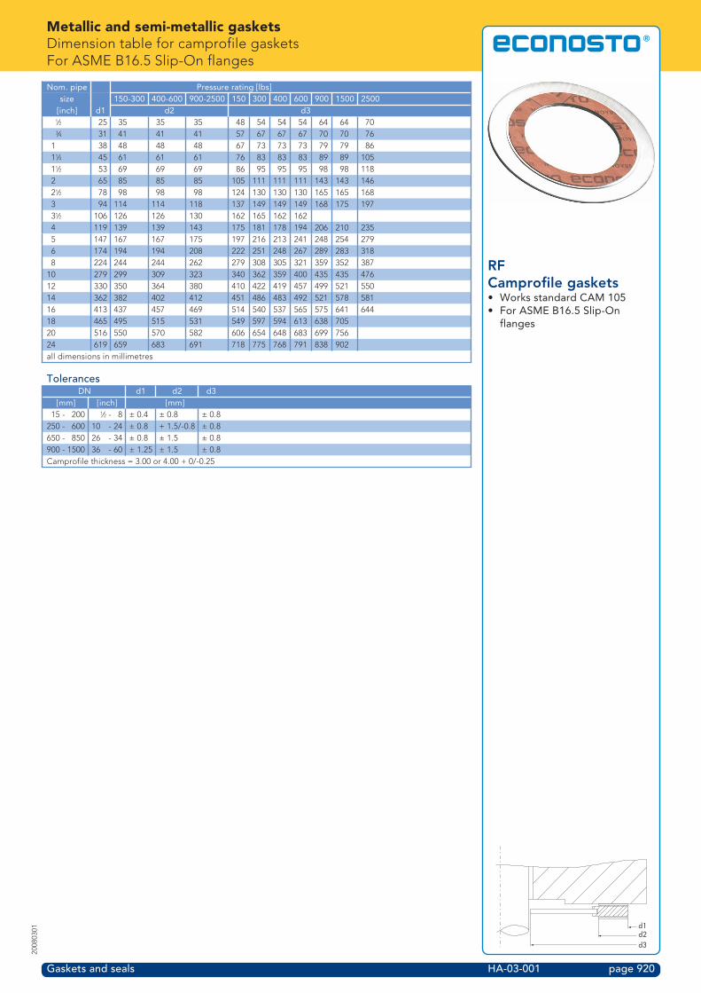
Metallic and semi-metallic gasketsDimension table for camprofile gasketsFor ASME B16.5 Slip-On flanges
Gaskets and seals HA-03-001 page 920
2008
0301
RFCamprofile gaskets• Works standard CAM 105• For ASME B16.5 Slip-On
flanges
Nom. pipe Pressure rating [lbs]size 150-300 400-600 900-2500 150 300 400 600 900 1500 2500
[inch] d1 d2 d3A 25 35 35 35 48 54 54 54 64 64 70C 31 41 41 41 57 67 67 67 70 70 76
1 38 48 48 48 67 73 73 73 79 79 861B 45 61 61 61 76 83 83 83 89 89 1051A 53 69 69 69 86 95 95 95 98 98 1182 65 85 85 85 105 111 111 111 143 143 1462A 78 98 98 98 124 130 130 130 165 165 1683 94 114 114 118 137 149 149 149 168 175 1973A 106 126 126 130 162 165 162 1624 119 139 139 143 175 181 178 194 206 210 2355 147 167 167 175 197 216 213 241 248 254 2796 174 194 194 208 222 251 248 267 289 283 3188 224 244 244 262 279 308 305 321 359 352 387
10 279 299 309 323 340 362 359 400 435 435 47612 330 350 364 380 410 422 419 457 499 521 55014 362 382 402 412 451 486 483 492 521 578 58116 413 437 457 469 514 540 537 565 575 641 64418 465 495 515 531 549 597 594 613 638 70520 516 550 570 582 606 654 648 683 699 75624 619 659 683 691 718 775 768 791 838 902all dimensions in millimetres
TolerancesDN d1 d2 d3
[mm] [inch] [mm]15 - 200 A - 8 ± 0.4 ± 0.8 ± 0.8
250 - 600 10 - 24 ± 0.8 + 1.5/-0.8 ± 0.8650 - 850 26 - 34 ± 0.8 ± 1.5 ± 0.8900 - 1500 36 - 60 ± 1.25 ± 1.5 ± 0.8Camprofile thickness = 3.00 or 4.00 + 0/-0.25
d1d2d3

Metallic and semi-metallic gasketsDimension table for camprofile gasketsFor ASME B16.47 series A flanges
Gaskets and seals HA-04-001 page 921
2008
0301
RFCamprofile gaskets• Works standard CAM 102• For ASME B16.47 series A
flanges
Nom. pipe Pressure rating [lbs]size 150-300 400-600 900 150 300 400 600 900
[inch] d1 d2 d326 650 685 705 725 774.7 835.2 831.9 866.9 882.728 705 745 765 785 831.9 898.7 892.3 914.4 946.230 755 795 820 840 882.7 952.5 946.2 971.6 1009.732 805 850 875 895 939.8 1006.6 1003.3 1022.4 1073.234 855 900 930 950 990.6 1057.4 1054.1 1073.2 1136.736 905 955 985 1005 1047.8 1117.6 1117.6 1130.3 1200.238 960 1015 1030 1065 1111.3 1054.1 1073.2 1104.9 1200.240 1010 1065 1085 1120 1162.1 1114.6 1127.3 1155.7 1251.042 1060 1120 1135 1175 1219.2 1165.4 1178.1 1219.2 1301.844 1110 1170 1190 1230 1276.4 1219.2 1231.9 1270.0 1368.646 1160 1225 1250 1285 1327.2 1273.3 1289.1 1327.2 1435.148 1210 1275 1300 1340 1384.3 1324.1 1346.2 1390.7 1485.950 1260 1330 1355 1435.1 1378.0 1403.4 1447.852 1310 1385 1405 1492.3 1428.8 1454.2 1498.654 1360 1435 1460 1549.4 1492.3 1517.7 1555.856 1410 1490 1515 1606.6 1543.1 1568.5 1612.958 1460 1540 1565 1663.7 1593.9 1619.3 1663.760 1510 1595 1625 1714.5 1644.7 1682.8 1733.6all dimensions in millimetres
TolerancesDN d1 d2 d3
[mm] [inch] [mm]15 - 200 A - 8 ± 0.4 ± 0.8 ± 0.8
250 - 600 10 - 24 ± 0.8 + 1.5/-0.8 ± 0.8650 - 850 26 - 34 ± 0.8 ± 1.5 ± 0.8900 - 1500 36 - 60 ± 1.25 ± 1.5 ± 0.8Camprofile thickness = 3.00 or 4.00 + 0/-0.25
d1d2d3

Metallic and semi-metallic gasketsDimension table for camprofile gasketsFor ASME B16.5 Tongue/Groove flanges
Gaskets and seals HA-05-001 page 922
2008
0301
Tongue/GrooveCamprofile gaskets• Works standard CAM 103• For ASME B16.5 flanges• Tongue/Groove
Nom. pipesize d1 d2
[inch] (narrow) (wide)A 25 35 35C 33 43 43
1 38 48 511B 48 57 641A 54 64 732 73 83 922A 86 95 1053 108 118 1273A 121 130 1404 132 145 1575 160 173 1866 190 203 2168 238 254 270
10 286 305 32412 343 362 38114 375 394 41316 425 448 47018 489 511 53520 535 559 58522 591 616 64124 640 667 690all dimensions in millimetres
TolerancesDN d1 d2 d3
[mm] [inch] [mm]15 - 200 A - 8 ± 0.4 ± 0.8 ± 0.8
250 - 600 10 - 24 ± 0.8 + 1.5/-0.8 ± 0.8650 - 850 26 - 34 ± 0.8 ± 1.5 ± 0.8900 - 1500 36 - 60 ± 1.25 ± 1.5 ± 0.8Camprofile thickness = 3.00 or 4.00 + 0/-0.25
d1d2

Metallic and semi-metallic gasketsDimension table for camprofile gasketsFor ASME B16.5 Male/Female flanges
Gaskets and seals HA-06-001 page 923
2008
0301
Male/FemaleCamprofile gaskets• Works standard CAM 104• For ASME B16.5 flanges• Male/Female
Nom. pipesize d1 d2 d1 d2
[inch] (narrow) (wide)A 18 21 35C 24 27 43
1 30 33 511B 38 42 641A 44 48 732 57 60 922A 68 73 1053 84 89 1273A 97 102 1404 zie opm. 110 114 1575 137 141 1866 162 168 2168 213 219 270
10 267 273 32412 318 324 38114 349 356 41316 400 406 47018 451 457 53520 502 510 58524 603 610 690all dimensions in millimetresRemark: d1 to be specified by customer
TolerancesDN d1 d2 d3
[mm] [inch] [mm]15 - 200 A - 8 ± 0.4 ± 0.8 ± 0.8
250 - 600 10 - 24 ± 0.8 + 1.5/-0.8 ± 0.8650 - 850 26 - 34 ± 0.8 ± 1.5 ± 0.8900 - 1500 36 - 60 ± 1.25 ± 1.5 ± 0.8Camprofile thickness = 3.00 or 4.00 + 0/-0.25
d1d2

Metallic and semi-metallic gasketsDimension table for camprofile gasketsFor DIN Raised Face flanges
Gaskets and seals HA-07-001 page 924
2008
0301
RFCamprofile gaskets• Works standard CAM 201• For DIN flanges• Raised Face (RF)
Nom. pipe Pressure rating PNsize 10-40 64-160 250-400 10 16 25 40 64 100 160 250 320 400[mm] d1 d2 d3
400 10 16 25 40 64 100 160 250 320 400[mm] d1 d2 d310 22 36 36 36 46 46 46 46 56 56 56 67 67 6715 26 42 42 42 51 51 51 51 61 61 61 72 7220 31 47 47 47 61 61 61 6125 36 52 52 52 71 71 71 71 82 82 82 83 92 10432 46 62 62 66 82 82 82 8240 53 69 69 73 92 92 92 92 103 103 103 109 119 13550 65 81 81 87 107 107 107 107 113 119 119 124 134 15065 81 100 100 103 127 127 127 127 137 143 143 153 170 19280 95 115 115 121 142 142 142 142 148 154 154 170 190 207
100 118 138 138 146 162 162 167 167 174 180 180 202 229 256125 142 162 162 178 192 192 193 193 210 217 217 242 274 301150 170 190 190 212 217 217 223 223 247 257 257 284 311 348175 195 215 215 245 247 247 253 265 277 287 284 316 358 402200 220 240 248 280 272 272 283 290 309 324 324 358 398 442250 270 290 300 340 327 328 340 352 364 391 388 442 488300 320 340 356 400 377 383 400 417 424 458 458 536350 375 395 415 437 443 457 474 486 512400 426 450 474 488 495 514 546 543 572500 530 560 588 594 617 624 628 657 704600 630 664 700 695 734 731 747 764 813700 730 770 812 810 804 833 852 879 950800 830 876 886 917 911 942 974 988900 930 982 994 1017 1011 1042 1084 1108
1000 1040 1098 1110 1124 1128 1154 1194 12201200 1250 1320 1334 1341 1342 1364 1398 14521400 1440 1522 1548 1542 1578 16181600 1650 1742 1772 1764 1798 18301800 1850 1914 1972 1964 20002000 2050 2120 2182 2168 22302200 2250 2328 2384 23782400 2460 2512 25942600 2670 2728 27942800 2890 2952 30143000 3100 3166 3228all dimensions in millimetres
TolerancesDN d1 d2 d3
[mm] [inch] [mm]15 - 200 A - 8 ± 0.4 ± 0.8 ± 0.8
250 - 600 10 - 24 ± 0.8 + 1.5/-0.8 ± 0.8650 - 850 26 - 34 ± 0.8 ± 1.5 ± 0.8900 - 1500 36 - 60 ± 1.25 ± 1.5 ± 0.8Camprofile thickness = 3.00 or 4.00 + 0/-0.25
d1d2d3

Metallic and semi-metallic gasketsDimension table for camprofile gasketsFor DIN Tongue/Groove flanges
Gaskets and seals HA-08-001 page 925
2008
0301
Tongue/GrooveCamprofile gaskets• Standard DIN 2512• For DIN flanges• Tongue/Groove
Nom. pipesize[mm] d1 d2
4-6 20 308 22 32
10 24 3415 29 3920 36 5025 43 5732 51 6540 61 7550 73 8765 95 10980 106 120
100 129 149125 155 175150 183 203175 213 233200 239 259250 292 312300 343 363350 395 421400 447 473500 549 575600 649 675700 751 777800 856 882900 961 987
1000 1062 1092all dimensions in millimetres
TolerancesDN d1 d2 d3
[mm] [inch] [mm]15 - 200 A - 8 ± 0.4 ± 0.8 ± 0.8
250 - 600 10 - 24 ± 0.8 + 1.5/-0.8 ± 0.8650 - 850 26 - 34 ± 0.8 ± 1.5 ± 0.8900 - 1500 36 - 60 ± 1.25 ± 1.5 ± 0.8Camprofile thickness = 3.00 or 4.00 + 0/-0.25
d1d2

Metallic and semi-metallic gasketsDimension table for camprofile gasketsFor DIN Male/Female flanges
Gaskets and seals HA-09-001 page 926
2008
0301
Male/FemaleCamprofile gaskets• Standard DIN 2513• For DIN flanges• Male/Female
Nom. pipesize[mm] d1 d2
10 18 3415 22 3920 28 5025 35 5732 43 6540 49 7550 61 8765 77 10980 90 120
100 115 149125 141 175150 169 203175 195 233200 220 259250 274 312300 325 363350 368 421400 420 473500 520 575600 620 675700 720 777800 820 882900 920 987
1000 1020 1091all dimensions in millimetres
TolerancesDN d1 d2 d3
[mm] [inch] [mm]15 - 200 A - 8 ± 0.4 ± 0.8 ± 0.8
250 - 600 10 - 24 ± 0.8 + 1.5/-0.8 ± 0.8650 - 850 26 - 34 ± 0.8 ± 1.5 ± 0.8900 - 1500 36 - 60 ± 1.25 ± 1.5 ± 0.8Camprofile thickness = 3.00 or 4.00 + 0/-0.25
d1d2

Metallic and semi-metallic gasketsSpiral wound gaskets
Gaskets and seals HA-10-001 page 927
2008
0301
Standard profile shapes• fig. 2004205• fig. 2004225• fig. 2004506• fig. 2004526• fig. 2005205• fig. 2005225• fig. 2005245• fig. 2005506• fig. 2005526• fig. 2005546
• ASME and DIN/EN• Wide gasket stress range• Solid construction• Very low leak rates (TA-Luft)• Blow-out proof• Easy assembly• Fire-safe
Spiral wound gaskets consist of a combination of profiled V-shaped metal strip and asoft (asbestos-free) filler material. These gaskets are very suitable as standard pipinggasket, particularly in higher pressure systems. The solid construction of the gasketmakes it blowout-proof and, in combination with a graphite filler material, it is suitablefor "Fire-Safe" applications.
ProfileSpiral wound gaskets are available standard in series 2004 (type SG) and in series 2005(type SG-IR)
Series 2004This is a standard spiral wound gasket that consists of a spiral wound element and anexternal centring ring.
Series 2005This is a standard spiral wound gasket that consists of a spiral wound element, and hasan external centring ring and an internal ring.
Sealing elementThe sealing element of a spiral wound gasket consists of a profiled metal V-strip,wound in combination with a soft filler material. The choice of material quality for thesealing element is based on the application field, medium and temperature.
Material Temperature Max. operating pressure Impermeability to gas ApplicationMin. Max.
[°C] [Bar]Graphite -200 550 250 Good aggressive mediaPTFE -200 250 100 Good aggressive mediaNovus ® -100 250 100 Good Liquids and gasesCeramica® -200 1100 100 Bad Very high temperatures
Outer ringFor standard piping systems the spiral wound gasket is always provided with a metalouter ring. This outer ring serves as centering ring between the bolts of the flange, asa result of which the sealing element is centered on the gasket surface (RF or FF) ofthe flange. The outer ring also functions as a compression stop to prevent the sealingelement from being overloaded by excessive tightening of the bolts.
Inner ringThe inner ring is used in the higher pressure classes to prevent distortion of thesealing element. Spiral wound gaskets with a PTFE filler material are always providedstandard with an inner ring. The material of the inner ring is standard the same as thematerial of the winding strip.
Ordering informationOrderingcode
Profile form Sealing element Outside ring Insidering
Gasket standard Flange standard
2004205 SG AISI 316L / Graphite CS (carbon steel) ASME B16.20 ASME B16.52004225 SG AISI 316L / Graphite AISI 316L ASME B16.20 ASME B16.52004506 SG AISI 316Ti / Graphite CS (carbon steel) EN 1514.2 DIN2004526 SG AISI 316Ti / Graphite AISI 316Ti EN 1514.2 DIN2005205 SGIR AISI 316L / Graphite CS (carbon steel) AISI
316LASME B16.20 ASME B16.5
2005225 SGIR AISI 316L / Graphite AISI 316L AISI316L
ASME B16.20 ASME B16.5
2005245 SGIR AISI 316L / PTFE CS (carbon steel) AISI316L
ASME B16.20 ASME B16.5
2005506 SGIR AISI 316Ti / Graphite CS (carbon steel) AISI316Ti
EN 1514.2 DIN
2005526 SGIR AISI 316Ti / Graphite AISI 316Ti AISI316Ti
EN 1514.2 DIN
2005546 SGIR AISI 316Ti / PTFE CS (carbon steel) AISI316Ti
EN 1514.2 DIN
Specify the following data when ordering:Fig.no. (profile shape) – sealing element materials - outer ring material – nominal dimension/rating - flangestandard- Other profile shapes, materials or material combinations are available on request- For other profile shapes see page HA-10-002- For dimensions, see dimension tables section
Series 2004 (type SG)
Series 2005 (type SG-IR)

Metallic and semi-metallic gasketsSpiral wound gaskets
Gaskets and seals HA-10-002 page 928
2008
0301
Other profile shapes• Series 2001• Series 2003• Series 2004• Series 2008• Series 2009• Series 2006• Series 2007
In addition to the shapes for standard piping systems, series 2004 and series 2005, anumber of different profile shapes is available on request:
Series 2001 (type RF1)The gasket consists of combined wound filler material and V-shaped metal strip. Thisprofile is usually used in tongue/groove flanges.
Series 2003 (type IR)This shape is identical to series 2001, however it has an internal ring. This profile isusually used in male/female flanges.
Series 2004 (type SG)For this shape, which is identical to the SG type, the dimensioning is specially adjustedto the use of spiral wound gaskets in combination with RTJ (Ring Type Joint) flanges.
Series 2008 (type HX-R)A type of gasket that consists of a spiral wound element around which a small, woundcentering ring is applied.The added centering windings ensure a correct centring in grooved flange facings(such as for heat exchangers)
Series 2009 (type HX-RIR)This type of gasket is identical to series 2008 (type HX-R), however it also has aninternal ring. This type of gasket is therefore suitable for fitting in male/female flanges.
Series 2006/2007 (type SG/GT and SG-IR/GT Gas-TightFor these profile shapes, which are identical to the 2004/2005 series with regard totheir basic profile, the spiral wound element consists of ceramic material, for instance,that has a number of graphite central windings to increase the gas-tightness.This provides a spiral wound gasket with the following characteristics:
• Non-contaminating for the medium• An improved gas-tightness
Non-standard shapesA spiral wound gasket can be manufactured and used in a large number of varieties. Itis possible to produce shapes with prefitted bars (heat exchangers), oval shapes(manholes and inspection holes), and many other different shapes.When using a spiral wound gasket with bars, use is generally made of metal jacketedbars.
Ordering informationSpecify the following data when ordering:Series number (profile shape) – sealing element materials (winding strip and fillermaterial) – outer and inner ring materials – nominal dimension/rating – flangestandard.With non-standard dimensions, the dimensions must also be specified, or a drawingmust be provided.
Series 2001 (type RF1)
Series 2003 (type IR)
Series 2004 (type SG)
Series 2008 (type HX-R)
Series 2009 (type HX-RIR)
GT-zone
Series 2006 - 2007 (type SG/GT, SG-IR/GT)
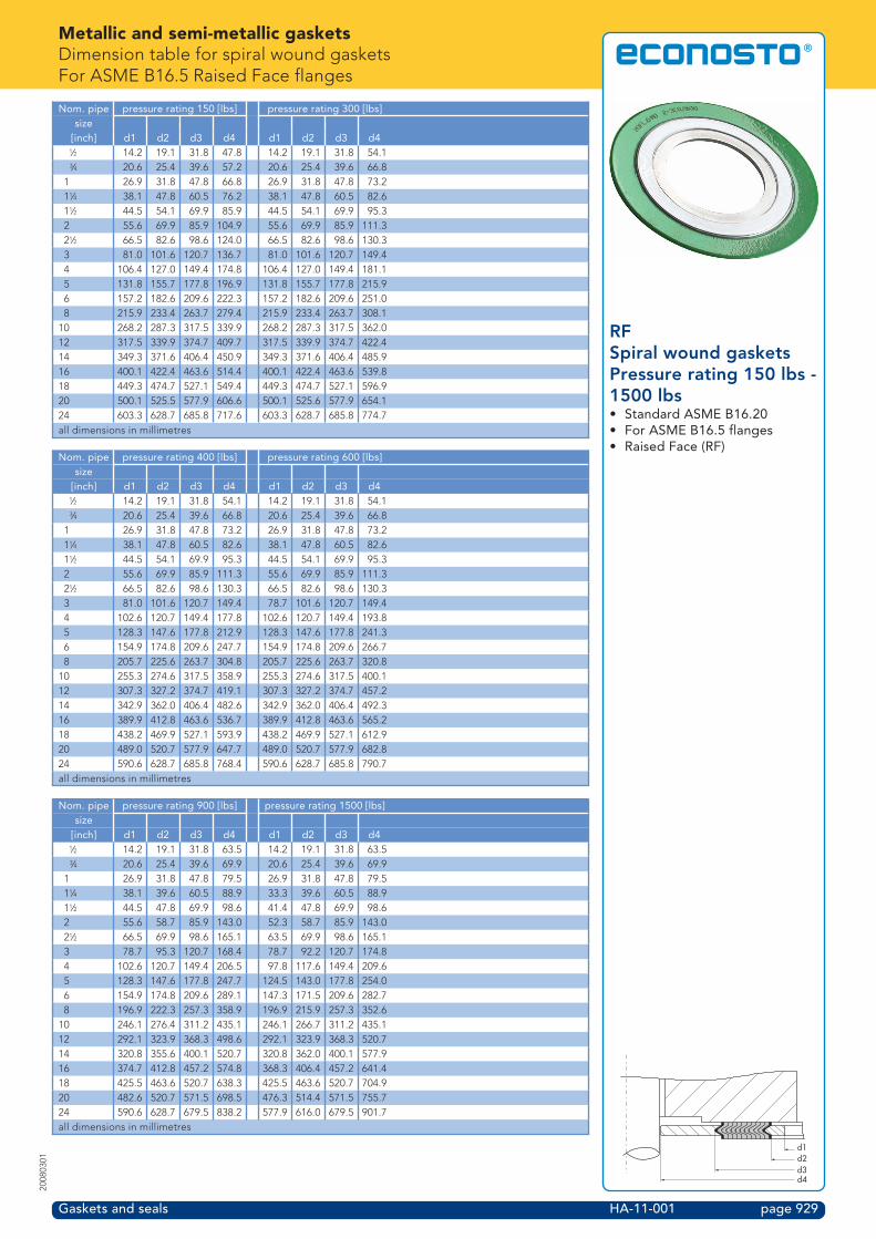
Metallic and semi-metallic gasketsDimension table for spiral wound gasketsFor ASME B16.5 Raised Face flanges
Gaskets and seals HA-11-001 page 929
2008
0301
RFSpiral wound gasketsPressure rating 150 lbs -1500 lbs• Standard ASME B16.20• For ASME B16.5 flanges• Raised Face (RF)
Nom. pipe pressure rating 150 [lbs] pressure rating 300 [lbs]size
[inch] d1 d2 d3 d4 d1 d2 d3 d4A 14.2 19.1 31.8 47.8 14.2 19.1 31.8 54.1C 20.6 25.4 39.6 57.2 20.6 25.4 39.6 66.8
1 26.9 31.8 47.8 66.8 26.9 31.8 47.8 73.21B 38.1 47.8 60.5 76.2 38.1 47.8 60.5 82.61A 44.5 54.1 69.9 85.9 44.5 54.1 69.9 95.32 55.6 69.9 85.9 104.9 55.6 69.9 85.9 111.32A 66.5 82.6 98.6 124.0 66.5 82.6 98.6 130.33 81.0 101.6 120.7 136.7 81.0 101.6 120.7 149.44 106.4 127.0 149.4 174.8 106.4 127.0 149.4 181.15 131.8 155.7 177.8 196.9 131.8 155.7 177.8 215.96 157.2 182.6 209.6 222.3 157.2 182.6 209.6 251.08 215.9 233.4 263.7 279.4 215.9 233.4 263.7 308.1
10 268.2 287.3 317.5 339.9 268.2 287.3 317.5 362.012 317.5 339.9 374.7 409.7 317.5 339.9 374.7 422.414 349.3 371.6 406.4 450.9 349.3 371.6 406.4 485.916 400.1 422.4 463.6 514.4 400.1 422.4 463.6 539.818 449.3 474.7 527.1 549.4 449.3 474.7 527.1 596.920 500.1 525.5 577.9 606.6 500.1 525.6 577.9 654.124 603.3 628.7 685.8 717.6 603.3 628.7 685.8 774.7all dimensions in millimetres
Nom. pipe pressure rating 400 [lbs] pressure rating 600 [lbs]size
[inch] d1 d2 d3 d4 d1 d2 d3 d4A 14.2 19.1 31.8 54.1 14.2 19.1 31.8 54.1C 20.6 25.4 39.6 66.8 20.6 25.4 39.6 66.8
1 26.9 31.8 47.8 73.2 26.9 31.8 47.8 73.21B 38.1 47.8 60.5 82.6 38.1 47.8 60.5 82.61A 44.5 54.1 69.9 95.3 44.5 54.1 69.9 95.32 55.6 69.9 85.9 111.3 55.6 69.9 85.9 111.32A 66.5 82.6 98.6 130.3 66.5 82.6 98.6 130.33 81.0 101.6 120.7 149.4 78.7 101.6 120.7 149.44 102.6 120.7 149.4 177.8 102.6 120.7 149.4 193.85 128.3 147.6 177.8 212.9 128.3 147.6 177.8 241.36 154.9 174.8 209.6 247.7 154.9 174.8 209.6 266.78 205.7 225.6 263.7 304.8 205.7 225.6 263.7 320.8
10 255.3 274.6 317.5 358.9 255.3 274.6 317.5 400.112 307.3 327.2 374.7 419.1 307.3 327.2 374.7 457.214 342.9 362.0 406.4 482.6 342.9 362.0 406.4 492.316 389.9 412.8 463.6 536.7 389.9 412.8 463.6 565.218 438.2 469.9 527.1 593.9 438.2 469.9 527.1 612.920 489.0 520.7 577.9 647.7 489.0 520.7 577.9 682.824 590.6 628.7 685.8 768.4 590.6 628.7 685.8 790.7all dimensions in millimetres
Nom. pipe pressure rating 900 [lbs] pressure rating 1500 [lbs]size
[inch] d1 d2 d3 d4 d1 d2 d3 d4A 14.2 19.1 31.8 63.5 14.2 19.1 31.8 63.5C 20.6 25.4 39.6 69.9 20.6 25.4 39.6 69.9
1 26.9 31.8 47.8 79.5 26.9 31.8 47.8 79.51B 38.1 39.6 60.5 88.9 33.3 39.6 60.5 88.91A 44.5 47.8 69.9 98.6 41.4 47.8 69.9 98.62 55.6 58.7 85.9 143.0 52.3 58.7 85.9 143.02A 66.5 69.9 98.6 165.1 63.5 69.9 98.6 165.13 78.7 95.3 120.7 168.4 78.7 92.2 120.7 174.84 102.6 120.7 149.4 206.5 97.8 117.6 149.4 209.65 128.3 147.6 177.8 247.7 124.5 143.0 177.8 254.06 154.9 174.8 209.6 289.1 147.3 171.5 209.6 282.78 196.9 222.3 257.3 358.9 196.9 215.9 257.3 352.6
10 246.1 276.4 311.2 435.1 246.1 266.7 311.2 435.112 292.1 323.9 368.3 498.6 292.1 323.9 368.3 520.714 320.8 355.6 400.1 520.7 320.8 362.0 400.1 577.916 374.7 412.8 457.2 574.8 368.3 406.4 457.2 641.418 425.5 463.6 520.7 638.3 425.5 463.6 520.7 704.920 482.6 520.7 571.5 698.5 476.3 514.4 571.5 755.724 590.6 628.7 679.5 838.2 577.9 616.0 679.5 901.7all dimensions in millimetres
d1d2d3d4

Metallic and semi-metallic gasketsDimension table for spiral wound gasketsFor ASME B16.5 Raised Face flanges
Gaskets and seals HA-11-002 page 930
2008
0301
RFSpiral wound gasketsPressure rating 2500 lbs• Standard ASME B16.20• For ASME B16.5 flanges• Raised Face (RF)
Nom. pipe pressure rating 2500 [lbs] pressure rating 2500 [lbssize
[inch] d1 d2 d3 d4A 14.2 19.1 31.8 69.9C 20.6 25.4 39.6 76.2
1 26.9 31.8 47.8 85.91B 33.3 39.6 60.5 104.91A 41.4 47.8 69.9 117.62 52.3 58.7 85.9 146.02A 63.5 69.9 98.6 168.43 78.7 92.2 120.7 196.94 97.8 117.6 149.4 235.05 124.5 143.0 177.8 279.46 147.3 171.5 209.6 317.58 196.9 215.9 257.3 387.4
10 246.1 270.0 311.2 476.312 292.1 317.5 368.3 549.4all dimensions in millimetres
d1d2d3d4
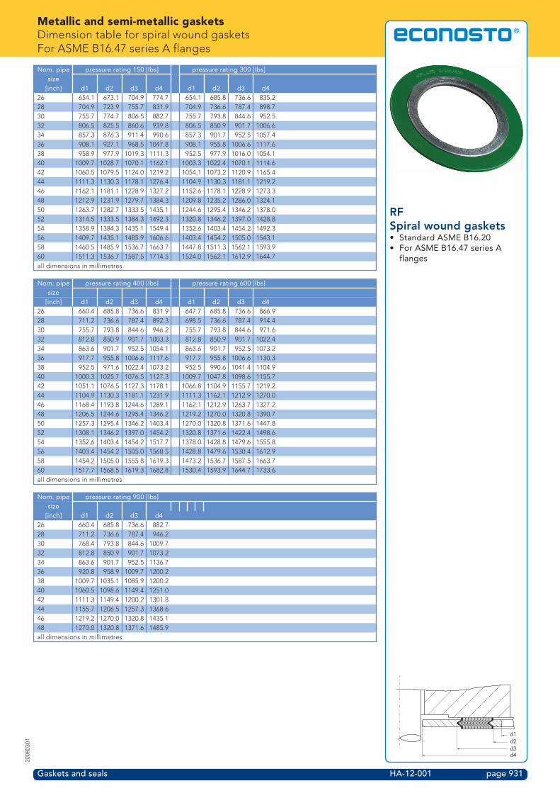
Metallic and semi-metallic gasketsDimension table for spiral wound gasketsFor ASME B16.47 series A flanges
Gaskets and seals HA-12-001 page 931
2008
0301
RFSpiral wound gaskets• Standard ASME B16.20• For ASME B16.47 series A
flanges
Nom. pipe pressure rating 150 [lbs] pressure rating 300 [lbs]size
[inch] d1 d2 d3 d4 d1 d2 d3 d426 654.1 673.1 704.9 774.7 654.1 685.8 736.6 835.228 704.9 723.9 755.7 831.9 704.9 736.6 787.4 898.730 755.7 774.7 806.5 882.7 755.7 793.8 844.6 952.532 806.5 825.5 860.6 939.8 806.5 850.9 901.7 1006.634 857.3 876.3 911.4 990.6 857.3 901.7 952.5 1057.436 908.1 927.1 968.5 1047.8 908.1 955.8 1006.6 1117.638 958.9 977.9 1019.3 1111.3 952.5 977.9 1016.0 1054.140 1009.7 1028.7 1070.1 1162.1 1003.3 1022.4 1070.1 1114.642 1060.5 1079.5 1124.0 1219.2 1054.1 1073.2 1120.9 1165.444 1111.3 1130.3 1178.1 1276.4 1104.9 1130.3 1181.1 1219.246 1162.1 1181.1 1228.9 1327.2 1152.6 1178.1 1228.9 1273.348 1212.9 1231.9 1279.7 1384.3 1209.8 1235.2 1286.0 1324.150 1263.7 1282.7 1333.5 1435.1 1244.6 1295.4 1346.2 1378.052 1314.5 1333.5 1384.3 1492.3 1320.8 1346.2 1397.0 1428.854 1358.9 1384.3 1435.1 1549.4 1352.6 1403.4 1454.2 1492.356 1409.7 1435.1 1485.9 1606.6 1403.4 1454.2 1505.0 1543.158 1460.5 1485.9 1536.7 1663.7 1447.8 1511.3 1562.1 1593.960 1511.3 1536.7 1587.5 1714.5 1524.0 1562.1 1612.9 1644.7all dimensions in millimetres
Nom. pipe pressure rating 400 [lbs] pressure rating 600 [lbs]size
[inch] d1 d2 d3 d4 d1 d2 d3 d426 660.4 685.8 736.6 831.9 647.7 685.8 736.6 866.928 711.2 736.6 787.4 892.3 698.5 736.6 787.4 914.430 755.7 793.8 844.6 946.2 755.7 793.8 844.6 971.632 812.8 850.9 901.7 1003.3 812.8 850.9 901.7 1022.434 863.6 901.7 952.5 1054.1 863.6 901.7 952.5 1073.236 917.7 955.8 1006.6 1117.6 917.7 955.8 1006.6 1130.338 952.5 971.6 1022.4 1073.2 952.5 990.6 1041.4 1104.940 1000.3 1025.7 1076.5 1127.3 1009.7 1047.8 1098.6 1155.742 1051.1 1076.5 1127.3 1178.1 1066.8 1104.9 1155.7 1219.244 1104.9 1130.3 1181.1 1231.9 1111.3 1162.1 1212.9 1270.046 1168.4 1193.8 1244.6 1289.1 1162.1 1212.9 1263.7 1327.248 1206.5 1244.6 1295.4 1346.2 1219.2 1270.0 1320.8 1390.750 1257.3 1295.4 1346.2 1403.4 1270.0 1320.8 1371.6 1447.852 1308.1 1346.2 1397.0 1454.2 1320.8 1371.6 1422.4 1498.654 1352.6 1403.4 1454.2 1517.7 1378.0 1428.8 1479.6 1555.856 1403.4 1454.2 1505.0 1568.5 1428.8 1479.6 1530.4 1612.958 1454.2 1505.0 1555.8 1619.3 1473.2 1536.7 1587.5 1663.760 1517.7 1568.5 1619.3 1682.8 1530.4 1593.9 1644.7 1733.6all dimensions in millimetres
Nom. pipe pressure rating 900 [lbs]size
[inch] d1 d2 d3 d426 660.4 685.8 736.6 882.728 711.2 736.6 787.4 946.230 768.4 793.8 844.6 1009.732 812.8 850.9 901.7 1073.234 863.6 901.7 952.5 1136.736 920.8 958.9 1009.7 1200.238 1009.7 1035.1 1085.9 1200.240 1060.5 1098.6 1149.4 1251.042 1111.3 1149.4 1200.2 1301.844 1155.7 1206.5 1257.3 1368.646 1219.2 1270.0 1320.8 1435.148 1270.0 1320.8 1371.6 1485.9all dimensions in millimetres
d1d2d3d4

Metallic and semi-metallic gasketsDimension table for spiral wound gasketsFor ASME B16.47 series B flanges
Gaskets and seals HA-13-001 page 932
2008
0301
RFSpiral wound gaskets• Standard ASME B16.20• For ASME B16.47 series B
flanges
Nom. pipe pressure rating 150 [lbs] pressure rating 300 [lbs]size
[inch] d1 d2 d3 d4 d1 d2 d3 d426 654.1 673.1 698.5 725.4 654.1 673.1 711.2 771.728 704.9 723.9 749.3 776.2 704.9 723.9 762.0 825.530 755.7 774.7 800.1 827.0 755.7 774.7 812.8 886.032 806.5 825.5 850.9 881.1 806.5 825.5 863.6 939.834 857.3 876.3 908.1 935.0 857.3 876.3 914.4 993.936 908.1 927.1 958.9 987.6 908.1 927.1 965.2 1047.838 958.9 974.6 1009.7 1044.7 971.6 1009.7 1047.8 1098.640 1009.7 1022.4 1063.8 1095.5 1022.4 1060.5 1098.6 1149.442 1060.5 1079.5 1114.6 1146.3 1085.9 1111.3 1149.4 1200.244 1111.3 1124.0 1165.4 1197.1 1124.0 1162.1 1200.2 1251.046 1162.1 1181.1 1224.0 1255.8 1178.1 1216.2 1254.3 1317.848 1212.9 1231.9 1270.0 1306.6 1200.2 1231.7 1270.0 1368.650 1263.7 1282.7 1325.6 1357.4 1267.0 1317.8 1355.9 1419.452 1314.5 1333.5 1376.4 1408.2 1317.8 1368.6 1406.7 1470.254 1365.3 1384.3 1422.4 1463.8 1365.3 1384.3 1422.4 1530.456 1422.4 1435.1 1472.2 1514.6 1428.8 1479.6 1524.0 1593.958 1478.0 1500.3 1528.8 1579.6 1484.4 1535.2 1573.3 1655.860 1535.2 1557.3 1586.0 1630.4 1557.3 1589.0 1630.4 1706.6all dimensions in millimetres
Nom. pipe pressure rating 400 [lbs] pressure rating 600 [lbs]size
[inch] d1 d2 d3 d4 d1 d2 d3 d426 654.1 666.8 698.5 746.3 644.7 663.7 714.5 765.328 701.8 714.5 749.3 800.1 692.2 704.9 755.7 819.230 752.6 765.3 806.5 857.3 752.6 778.0 828.8 879.632 800.1 812.8 860.6 911.4 793.8 831.9 882.7 933.534 850.9 866.9 911.4 962.2 850.9 889.0 939.8 997.036 898.7 917.7 965.2 1022.4 901.7 939.8 990.6 1047.838 952.5 971.6 1022.4 1073.2 952.5 990.6 1041.4 1104.940 1000.3 1025.7 1076.5 1127.3 1009.7 1047.8 1098.6 1155.742 1051.1 1076.5 1127.3 1178.1 1066.8 1104.9 1155.7 1219.244 1104.9 1130.3 1181.1 1231.9 1111.3 1162.1 1212.9 1270.046 1168.4 1193.8 1244.6 1289.1 1162.1 1212.9 1263.7 1327.248 1206.5 1244.6 1295.4 1346.2 1219.2 1270.0 1320.8 1390.750 1257.3 1295.4 1346.2 1403.4 1270.0 1320.8 1371.6 1447.852 1308.1 1346.2 1397.0 1454.2 1320.8 1371.6 1422.4 1498.654 1352.6 1403.4 1454.2 1517.7 1378.0 1428.8 1479.6 1555.856 1403.4 1454.2 1505.0 1568.5 1428.8 1479.6 1530.4 1612.958 1454.2 1505.0 1555.8 1619.3 1473.2 1536.7 1587.5 1663.760 1517.7 1568.5 1619.3 1682.8 1557.3 1589.0 1630.4 1706.6all dimensions in millimetres
Nom. pipe pressure rating 900 [lbs]size
[inch] d1 d2 d3 d426 666.8 692.2 749.3 838.228 717.6 743.0 800.1 901.730 781.8 806.5 857.3 958.932 838.2 863.6 914.4 1016.034 895.4 920.8 971.6 1073.236 920.8 946.2 997.0 1124.038 1009.7 1035.1 1085.9 1200.240 1060.5 1098.6 1149.4 1251.042 1111.3 1149.4 1200.2 1301.844 1155.7 1206.5 1257.3 1368.646 1219.2 1270.0 1320.8 1435.148 1270.0 1320.8 1371.6 1485.9all dimensions in millimetres
d1d2d3d4

Metallic and semi-metallic gasketsDimension table for spiral wound gasketsFor ASME B16.5 Male/Female flanges
Gaskets and seals HA-14-001 page 933
2008
0301
Male/FemaleSpiral wound gaskets• Works standard SPW3• For ASME B16.5 flanges• Male/Female• Series 2001 (type RF1)
Nom. pipesize d1 d2 d1 d2
[inch] narrow wideA 18 21 35C 24 27 43
1 30 33 511B 38 42 641A 44 48 732 57 60 922A 68 73 1053 84 89 1273A 97 102 1404 Opm. 110 114 1575 137 141 1866 162 168 2168 213 219 270
10 267 273 32412 318 324 38114 349 356 41316 400 406 47018 451 457 53520 502 510 58524 603 610 690all dimensions in millimetresRem. To be specified by the user
d1d2

Metallic and semi-metallic gasketsDimension table for spiral wound gasketsFor ASME B16.5 Tongue/Groove flanges
Gaskets and seals HA-15-001 page 934
2008
0301
Tongue/GrooveSpiral wound gaskets• Works standard SPW4• For ASME B16.5 flanges• Tongue/Groove• Series 2001 (type RF1)
Nom. pipesize d1 d2
[inch] (narrow) (wide)A 25 35 35C 33 43 43
1 38 48 511B 48 57 641A 54 64 732 73 83 922A 86 95 1053 108 118 1273A 121 130 1404 132 145 1575 160 173 1866 190 203 2168 238 254 270
10 286 305 32412 343 362 38114 375 394 41316 425 448 47018 489 511 53520 535 559 58522 591 616 64124 640 667 690all dimensions in millimetres
d1d2
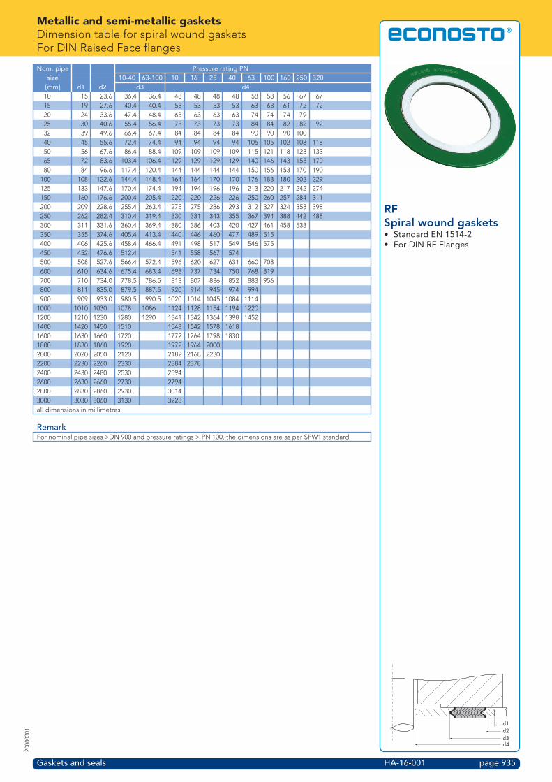
Metallic and semi-metallic gasketsDimension table for spiral wound gasketsFor DIN Raised Face flanges
Gaskets and seals HA-16-001 page 935
2008
0301
RFSpiral wound gaskets• Standard EN 1514-2• For DIN RF Flanges
Nom. pipe Pressure rating PNsize 10-40 63-100 10 16 25 40 63 100 160 250 320[mm] d1 d2 d3 d410 15 23.6 36.4 36.4 48 48 48 48 58 58 56 67 6715 19 27.6 40.4 40.4 53 53 53 53 63 63 61 72 7220 24 33.6 47.4 48.4 63 63 63 63 74 74 74 7925 30 40.6 55.4 56.4 73 73 73 73 84 84 82 82 9232 39 49.6 66.4 67.4 84 84 84 84 90 90 90 10040 45 55.6 72.4 74.4 94 94 94 94 105 105 102 108 11850 56 67.6 86.4 88.4 109 109 109 109 115 121 118 123 13365 72 83.6 103.4 106.4 129 129 129 129 140 146 143 153 17080 84 96.6 117.4 120.4 144 144 144 144 150 156 153 170 190
100 108 122.6 144.4 148.4 164 164 170 170 176 183 180 202 229125 133 147.6 170.4 174.4 194 194 196 196 213 220 217 242 274150 160 176.6 200.4 205.4 220 220 226 226 250 260 257 284 311200 209 228.6 255.4 263.4 275 275 286 293 312 327 324 358 398250 262 282.4 310.4 319.4 330 331 343 355 367 394 388 442 488300 311 331.6 360.4 369.4 380 386 403 420 427 461 458 538350 355 374.6 405.4 413.4 440 446 460 477 489 515400 406 425.6 458.4 466.4 491 498 517 549 546 575450 452 476.6 512.4 541 558 567 574500 508 527.6 566.4 572.4 596 620 627 631 660 708600 610 634.6 675.4 683.4 698 737 734 750 768 819700 710 734.0 778.5 786.5 813 807 836 852 883 956800 811 835.0 879.5 887.5 920 914 945 974 994900 909 933.0 980.5 990.5 1020 1014 1045 1084 1114
1000 1010 1030 1078 1086 1124 1128 1154 1194 12201200 1210 1230 1280 1290 1341 1342 1364 1398 14521400 1420 1450 1510 1548 1542 1578 16181600 1630 1660 1720 1772 1764 1798 18301800 1830 1860 1920 1972 1964 20002000 2020 2050 2120 2182 2168 22302200 2230 2260 2330 2384 23782400 2430 2480 2530 25942600 2630 2660 2730 27942800 2830 2860 2930 30143000 3030 3060 3130 3228all dimensions in millimetres
RemarkFor nominal pipe sizes >DN 900 and pressure ratings > PN 100, the dimensions are as per SPW1 standard
d1d2d3d4

Metallic and semi-metallic gasketsDimension table for spiral wound gasketsFor DIN 2513 Male/Female flanges
Gaskets and seals HA-17-001 page 936
2008
0301
Male/FemaleSpiral wound gaskets• Standard DIN 2692• For DIN 2513 flanges• Male/Female• Series 2001 (type RF1)
Nom. pipesize[mm] d1 d2
10 18 3415 22 3920 28 5025 35 5732 43 6540 49 7550 61 8765 77 10980 90 120
100 115 149125 141 175150 169 203175 195 233200 220 259250 274 312300 325 363350 368 421400 420 473500 520 575600 620 675700 720 777800 820 882900 920 987
1000 1020 1091all dimensions in millimetres
d1d2

Metallic and semi-metallic gasketsDimension table for spiral wound gasketsFor DIN 2512 Tongue/Groove flanges
Gaskets and seals HA-18-001 page 937
2008
0301
Tongue/GrooveSpiral wound gaskets• Standard DIN 2691• For DIN 2512 flanges• Tongue/Groove• Series 2001 (type RF1)
Nom. pipesize[mm] d1 d2
4-6 20 308 22 32
10 24 3415 29 3920 36 5025 43 5732 51 6540 61 7550 73 8765 95 10980 106 120
100 129 149125 155 175150 183 203175 213 233200 239 259250 292 312300 343 363350 395 421400 447 473500 549 575600 649 675700 751 777800 856 882900 961 987
1000 1062 1092all dimensions in millimetres
d1d2

Metallic and semi-metallic gasketsRing Joint gaskets
Gaskets and seals HA-19-001 page 938
2008
0301
For standard ASME, APIpiping systems• fig. 2071101• fig. 2071104• fig. 2071141• fig. 2072101• fig. 2072104• fig. 2072141• fig. 2074101• fig. 2074104• fig. 2074141• fig. 2073101• fig. 2073104• fig. 2073141
• High and changing pressuresup to 1500 bar
• High reliability• Easy assembly• Comply with ASME B16.20 and
API-6A requirements
Ring Joint gaskets are solid metal sealing rings, suitable for application at highpressures and temperatures. Ring Joint gaskets are used in combination with specialflanges with a groove, that together with the correct choice of material and profileshape, realize a very reliable seal.Ring Joint gaskets are manufactured on high quality computer-controlled CNC lathesand comply with the requirements stated in the ASME B16.20 and API 6a standards.
Profile shapesRing Joint gaskets are available standard in the following profile shapes:
Series 2071 (type R-oval, M8)This is a standard Ring Joint gasket, with oval design and designed for flanges withstandard Ring Joint grooves.
Series 2072 (type R Octagonal, M9)This is a standard Ring Joint gasket, with octagonal design and designed for flangeswith standard Ring Joint grooves.
Series 2074 (type RX, M12)This is a Ring Joint gasket for pressures up to approx. 700 bar. For this version, whichis self-energizing, the external sealing surfaces make the first contact with the flanges.A higher system pressure produces a higher surface pressure. Ring Joint gaskets ofthe RX type are interchangeable with the standard R types. However, the length of thebolt have to be increased due to the greater height of the RX profiles.
Series 2073 (type BX, M11)This is a Ring Joint gasket for use at very high pressures (up to approx. 1500 bar). ThisRing Joint gasket is only suitable for API type BX flanges and grooves.
Hardness of Ring Joint gasketsDepending on the type of material, Ring Joint gaskets are provided with hardnessesas given in the table below:
Material HRB (max) HB (max)Rockwell-B Brinell
Soft Iron (D) 56 90Low Carbon Steel (S) 68 120ASTM A-182 F5 72 130SS 83 160
Ordering informationOrdering code Profile form Material Gasket standard Flange standard2071101 R-oval Soft Iron (D) Oiled ASME B16.20/API-6A ASME B16.5/ISO70052071104 R-oval Soft Iron (D) Galvanized ASME B16.20/API-6A ASME B16.5/ISO70052071141 R-oval AISI 316L ASME B16.20/API-6A ASME B16.5/ISO70052072101 R octagonal Soft Iron (D) Oiled ASME B16.20/API-6A ASME B16.5/ISO70052072104 R octagonal Soft Iron (D) Galvanized ASME B16.20/API-6A ASME B16.5/ISO70052072141 R octagonal AISI 316L ASME B16.20/API-6A ASME B16.5/ISO70052074101 RX Soft Iron (D) Oiled ASME B16.20/API-6A ASME B16.5/ISO70052074104 RX Soft Iron (D) Galvanized ASME B16.20/API-6A ASME B16.5/ISO70052074141 RX AISI 316L ASME B16.20/API-6A ASME B16.5/ISO70052073101 BX Soft Iron (D) Oiled ASME B16.20/API-6A API-6A type BX2073104 BX Soft Iron (D) Galvanized ASME B16.20/API-6A API-6A type BX2073141 BX AISI 316L ASME B16.20/API-6A API-6A type BXSpecify the following data when ordering:Fig.no. (profile shape) – ring number - material- Other materials available on request- For dimensions see dimension tables
Series 2071 (type R-oval, M8)
Series 2072 (type R-octagonal, M9)
Series 2074 (type RX)
Series 2073 (Type BX)

Metallic and semi-metallic gasketsSelection table for Ring Joint gaskets, types R or RXFor ASME B16.5 and BS 1560 flanges
Gaskets and seals HA-20-001 page 939
2008
0301
Ring Joint gaskets• Type R-oval• Type R-octagonal• Type RX• For ASME B16.5 flanges• For BS 1560 flanges
Nom. pipe Pressure rating [lbs]size
[inch] 150 300 400 600 900 1500 2500A R11 R11 R12 R12 R13C R13 R13 R14 R14 R16
1 R15 R16 R16 R16 R16 R181B R17 R18 R18 R18 R18 R211A R19 R/RX20 R/RX20 R/RX20 R/RX20 R/RX232 R22 R/RX23 R/RX23 R/RX24 R/RX24 R/RX262A R/RX25 R/RX26 R/RX26 R/RX27 R/RX27 R283 R29 R/RX31 R/RX31 R/RX31 R/RX35 R323A R33 R34 R344 R36 R/RX37 R/RX37 R/RX37 R/RX37 R/RX39 R385 R40 R/RX41 R/RX41 R/RX41 R/RX41 R/RX44 R426 R43 R/RX45 R/RX45 R/RX45 R/RX45 R/RX46 R/RX478 R48 R/RX49 R/RX49 R/RX49 R/RX49 R/RX50 R51
10 R52 R/RX53 R/RX53 R/RX53 R/RX53 R/RX54 R5512 R56 R/RX57 R/RX57 R/RX57 R/RX57 R58 R6014 R59 R61 R61 R61 R62 R/RX6316 R64 R/RX65 R/RX65 R/RX65 R/RX66 R6718 R68 R/RX69 R/RX69 R/RX69 R/RX70 R7120 R72 R/RX73 R/RX73 R/RX73 R/RX74 R7524 R76 R77 R77 R77 R78 R79

Metallic and semi-metallic gasketsSelection table for Ring Joint gaskets, type BXFor API spec. 6A, type 6BX flanges
Gaskets and seals HA-21-001 page 940
2008
0301
Ring Joint gaskets• Type BX• For API spec. 6A, type 6BX
flanges
Nom. pipe Pressure rating [psi]size
[inch] 2000 3000 5000 10000 15000 200001ı BX150 BX1501N BX151 BX151 BX1512˚ BX152 BX152 BX1522 9/16 BX153 BX153 BX1533˚ BX154 BX154 BX1544˚ BX155 BX155 BX1555D BX1697˚ BX156 BX156 BX1569 BX159 BX157 BX157
11 BX158 BX158 BX15813˙ BX160 BX159 BX159 BX15916C BX162 BX16218C BX163 BX164 BX16421B BX165 BX16626C BX167 BX16830 BX303 BX303

Metallic and semi-metallic gasketsSelection table for Ring Joint gaskets, types R or RXFor ASME B16.47 series A flanges
Gaskets and seals HA-22-001 page 941
2008
0301
Ring Joint gaskets• Type R-oval• Type R-octagonal• Type RX• For ASME B16.47 series A
flanges
Nom. pipe Pressure rating [lbs]size
[inch] 300-600 90026 R93 R10028 R94 R10130 R95 R10232 R96 R10334 R97 R10436 R98 R105
For flanges > 36" there are no standard Ring Joint gaskets available

Metallic and semi-metallic gasketsSelection table for Ring Joint gaskets, type R or RXFor API spec. 6A, model 6B flanges
Gaskets and seals HA-23-001 page 942
2008
0301
Ring Joint gaskets• Type R-oval• Type R-octagonal• Type RX• For API spec. 6A, model 6B
flanges
Nom. pipe Pressure rating [lbs]size
[inch] 2000 3000 50002˚ R/RX23 R/RX24 R/RX242 9/16 R/RX26 R/RX27 R/RX273D R/RX31 R/RX31 R/RX354˚ R/RX37 R/RX37 R/RX395D R/RX41 R/RX41 R/RX447˚ R/RX45 R/RX45 R/RX469 R/RX49 R/RX49 R/RX50
11 R/RX53 R/RX53 R/RX5413˙ R/RX57 R/RX5716C R/RX65 R/RX6620C R/RX7421B R/RX73

Metallic and semi-metallic gasketsSelection table for Ring Joint gaskets, type RXFor segmented API spec. 6A flanges
Gaskets and seals HA-24-001 page 943
2008
0301
Ring Joint gaskets• Type RX• For segmented API spec. 6A
flanges
Nom. pipe Pressure rating 5000 lbssize
[inch] Dual Triple/Quadruple1˘ RX2011N RX205 RX2052˚ RX20 RX202 9/16 RX210 RX2103D RX25 RX254˚ RX215 RX2154˚ x 4B RX215 RX215

Metallic and semi-metallic gasketsDimension table for Ring Joint gaskets and grooves, type RAs per ASME B16.20, API spec. 6A and ISO 7483
Gaskets and seals HA-25-001 page 944
2008
0301
Ring Joint gaskets• Type R-oval• Type R-octagonal• Standard ASME B16.20• Standard API spec 6A• Standard ISO 7483
Ring Ring [mm] Groove [mm] Weight [kg]**number P A B H C R1 E F R2 Oval OctagonalR11 34.13 6.35 11.11 9.53 4.32 1.6 5.56 7.14 0.8 0.05 0.04R12 39.69 7.94 14.29 12.70 5.23 1.6 6.35 8.73 0.8 0.10 0.08R13 42.86 7.94 14.29 12.70 5.23 1.6 6.35 8.73 0.8 0.11 0.09R14 44.45 7.94 14.29 12.70 5.23 1.6 6.35 8.73 0.8 0.11 0.09R15 47.63 7.94 14.29 12.70 5.23 1.6 6.35 8.73 0.8 0.12 0.10R16 50.80 7.94 14.29 12.70 5.23 1.6 6.35 8.73 0.8 0.13 0.11R17 57.15 7.94 14.29 12.70 5.23 1.6 6.35 8.73 0.8 0.14 0.12R18 60.33 7.94 14.29 12.70 5.23 1.6 6.35 8.73 0.8 0.15 0.12R19 65.09 7.94 14.29 12.70 5.23 1.6 6.35 8.73 0.8 0.16 0.13R20* 68.26 7.94 14.29 12.70 5.23 1.6 6.35 8.73 0.8 0.17 0.14R21 72.23 11.11 17.46 15.88 7.75 1.6 7.94 11.91 0.8 0.30 0.27R22 82.55 7.94 14.29 12.70 5.23 1.6 6.35 8.73 0.8 0.20 0.17R23* 82.55 11.11 17.46 15.88 7.75 1.6 7.94 11.91 0.8 0.34 0.31R24* 95.25 11.11 17.46 15.88 7.75 1.6 7.94 11.91 0.8 0.40 0.35R25 101.60 7.94 14.29 12.70 5.23 1.6 6.35 8.73 0.8 0.25 0.21R26* 101.60 11.11 17.46 15.88 7.75 1.6 7.94 11.91 0.8 0.42 0.38R27* 107.95 11.11 17.46 15.88 7.75 1.6 7.94 11.91 0.8 0.45 0.40R28 111.13 12.70 19.05 17.46 8.66 1.6 9.53 13.49 1.6 0.57 0.51R29 114.30 7.94 14.29 12.70 5.23 1.6 6.35 8.73 0.8 0.28 0.24R30 117.48 11.11 17.46 15.88 7.75 1.6 7.94 11.91 0.8 0.49 0.44R31* 123.83 11.11 17.46 15.88 7.75 1.6 7.94 11.91 0.8 0.51 0.46R32 127.00 12.70 19.05 17.46 8.66 1.6 9.53 13.49 1.6 0.65 0.58R33 131.76 7.94 14.29 12.70 5.23 1.6 6.35 8.73 0.8 0.33 0.27R34 131.76 11.11 17.46 15.88 7.75 1.6 7.94 11.91 0.8 0.55 0.49R35* 136.53 11.11 17.46 15.88 7.75 1.6 7.94 11.91 0.8 0.57 0.51R36 149.23 7.94 14.29 12.70 5.23 1.6 6.35 8.73 0.8 0.37 0.31R37* 149.23 11.11 17.46 15.88 7.75 1.6 7.94 11.91 0.8 0.62 0.55R38 157.16 15.88 22.23 20.64 10.49 1.6 11.11 16.67 1.6 1.16 1.01R39* 161.93 11.11 17.46 15.88 7.75 1.6 7.94 11.91 0.8 0.67 0.60R40 171.45 7.94 14.29 12.70 5.23 1.6 6.35 8.73 0.8 0.42 0.36R41* 180.98 11.11 17.46 15.88 7.75 1.6 7.94 11.91 0.8 0.75 0.67R42 190.50 19.05 25.40 23.81 12.32 1.6 12.70 19.84 1.6 1.92 1.64R43 193.68 7.94 14.29 12.70 5.23 1.6 6.35 8.73 0.8 0.48 0.40R44* 193.68 11.11 17.46 15.88 7.75 1.6 7.94 11.91 0.8 0.80 0.72R45* 211.14 11.11 17.46 15.88 7.75 1.6 7.94 11.91 0.8 0.88 0.78R46* 211.14 12.70 19.05 17.46 8.66 1.6 9.53 13.49 1.6 1.09 0.96R47* 228.60 19.05 25.40 23.81 12.32 1.6 12.70 19.84 1.6 2.30 1.97R48 247.65 7.94 14.29 12.70 5.23 1.6 6.35 8.73 0.8 0.61 0.51R49* 269.88 11.11 17.46 15.88 7.75 1.6 7.94 11.91 0.8 1.12 1.00R50* 269.88 15.88 22.23 20.64 10.49 1.6 11.11 16.67 1.6 2.00 1.74R51 279.40 22.23 28.58 26.99 14.81 1.6 14.29 23.02 1.6 3.67 3.26* Specified in API spec. 6A.** The weight is based on a specific mass of 7.9 g/cm3
Tolerances, type RA ring width ± 0.20 mmB ring height, oval ± 0.51 mmH ring height, octagonal ± 0.51 mmC width of the bottom surface ± 0.20 mmE groove depth + 0.51/0.00 mmF groove width ± 0.20 mmP Avg. pitch diameter of the ring ± 0.18 mm
Av. pitch diameter of the groove ± 0.13 mmR1 radius of the ring ± 0.51 mmR2 radius in the groove max.23° corner ± A°
The surface roughness of the 23° sides is max. 1.58 µm Ra
E
F
R2
P23°
A
B
P
CA
H
P23°
R1

Metallic and semi-metallic gasketsDimension table for Ring Joint gaskets and grooves, type RAs per ASME B16.20, API spec. 6A and ISO 7483 (continued)
Gaskets and seals HA-26-001 page 945
2008
0301
Ring Joint gaskets• Type R-oval• Type R-octagonal• Standard ASME B16.20• Standard API spec 6A• Standard ISO 7483
Ring Ring [mm] Groove [mm] Weight [kg]**number P A B H C R1 E F R2 Oval OctagonalR52 304.80 7.94 14.29 12.70 5.23 1.6 6.35 8.73 0.8 0.76 0.63R53* 323.85 11.11 17.46 15.88 7.75 1.6 7.94 11.91 0.8 1.35 1.20R54* 323.85 15.88 22.23 20.64 10.49 1.6 11.11 16.67 1.6 2.40 2.08R55 342.90 28.58 36.51 34.93 19.81 2.4 17.46 30.16 2.4 7.38 6.95R56 381.00 7.94 14.29 12.70 5.23 1.6 6.35 8.73 0.8 0.94 0.79R57* 381.00 11.11 17.46 15.88 7.75 1.6 7.94 11.91 0.8 1.58 1.42R58 381.00 22.23 28.58 26.99 14.81 1.6 14.29 23.02 1.6 5.00 4.44R59 396.88 7.94 14.29 12.70 5.23 1.6 6.35 8.73 0.8 0.98 0.82R60 406.40 31.75 39.69 38.10 22.33 2.4 17.46 33.34 2.4 10.52 10.09R61 419.10 11.11 17.46 15.88 7.75 1.6 7.94 11.91 0.8 1.74 1.56R62 419.10 15.88 22.23 20.64 10.49 1.6 11.11 16.67 1.6 3.11 2.70R63* 419.10 25.40 33.34 31.75 17.30 2.4 15.88 26.99 2.4 7.36 6.78R64 454.03 7.94 14.29 12.70 5.23 1.6 6.35 8.73 0.8 1.13 0.94R65* 469.90 11.11 17.46 15.88 7.75 1.6 7.94 11.91 0.8 1.95 1.75R66* 469.90 15.88 22.23 20.64 10.49 1.6 11.11 16.67 1.6 3.48 3.02R67 469.90 28.58 36.51 34.93 19.81 2.4 17.46 30.16 2.4 10.12 9.52R68 517.53 7.94 14.29 12.70 5.23 1.6 6.35 8.73 0.8 1.28 1.07R69* 533.40 11.11 17.46 15.88 7.75 1.6 7.94 11.91 0.8 2.22 1.98R70* 533.40 19.05 25.40 23.81 12.32 1.6 12.70 19.84 1.6 5.37 4.59R71 533.40 28.58 36.51 34.93 19.81 2.4 17.46 30.16 2.4 11.48 10.81R72 558.80 7.94 14.29 12.70 5.23 1.6 6.35 8.73 0.8 1.38 1.16R73* 584.20 12.70 19.05 17.46 8.66 1.6 9.53 13.49 1.6 3.00 2.66R74* 584.20 19.05 25.40 23.81 12.32 1.6 12.70 19.84 1.6 5.88 5.03R75 584.20 31.75 39.69 38.10 22.33 2.4 17.46 33.34 2.4 15.12 14.50R76 673.10 7.94 14.29 12.70 5.23 1.6 6.35 8.73 0.8 1.67 1.39R77 692.15 15.88 22.23 20.64 10.49 1.6 11.11 16.67 1.6 5.13 4.45R78 692.15 25.40 33.34 31.75 17.30 2.4 15.88 26.99 2.4 12.16 11.19R79 692.15 34.93 44.45 41.28 24.82 2.4 20.64 36.51 2.4 22.15 20.62R80 615.95 7.94 12.70 5.23 1.6 6.35 8.73 0.8 1.28R81 635.00 14.29 19.05 9.58 1.6 11.11 15.08 1.6 3.46R82* 57.15 11.11 15.88 7.75 1.6 7.94 11.91 0.8 0.21R84* 63.50 11.11 15.88 7.75 1.6 7.94 11.91 0.8 0.24R85* 79.38 12.70 17.46 8.66 1.6 9.53 13.49 1.6 0.36R86* 90.49 15.88 20.64 10.49 1.6 11.11 16.67 1.6 0.58R87* 100.01 15.88 20.64 10.49 1.6 11.11 16.67 1.6 0.64R88* 123.83 19.05 23.81 12.32 1.6 12.70 19.84 1.6 1.07R89* 114.30 19.05 23.81 12.32 1.6 12.70 19.84 1.6 0.98R90* 155.58 22.23 26.99 14.81 1.6 14.29 23.02 1.6 1.81R91* 260.35 31.75 38.10 22.33 2.4 17.46 33.34 2.4 6.46R92 228.60 11.11 17.46 15.88 7.75 1.6 7.94 11.91 0.8 0.95 0.85R93 749.30 19.05 23.81 12.32 1.6 12.70 19.84 1.6 6.45R94 800.10 19.05 23.81 12.32 1.6 12.70 19.84 1.6 6.88R95 857.25 19.05 23.81 12.32 1.6 12.70 19.84 1.6 7.37R96 914.40 22.23 26.99 14.81 1.6 14.29 23.02 1.6 10.66R97 965.20 22.23 26.99 14.81 1.6 14.29 23.02 1.6 11.26R98 1022.35 22.23 26.99 14.81 1.6 14.29 23.02 1.6 11.92R99* 234.95 11.11 15.88 7.75 1.6 7.94 11.91 0.8 0.87R100 749.30 28.58 34.93 19.81 2.4 17.46 30.16 2.4 15.18R101 800.10 31.75 38.10 22.33 2.4 17.46 33.34 2.4 19.86R102 857.25 31.75 38.10 22.33 2.4 17.46 33.34 2.4 21.27R103 914.40 31.75 38.10 22.33 2.4 17.46 33.34 2.4 22.69R104 965.20 34.93 41.28 24.82 2.4 20.64 36.51 2.4 28.75R105 1022.35 34.93 41.28 24.82 2.4 20.64 36.51 2.4 30.45* Specified in API spec. 6A.** The weight is based on a specific mass of 7.9 g/cm3
Tolerances, type RA ring width ± 0.20 mmB ring height, oval ± 0.51 mmH ring height, octagonal ± 0.51 mmC width of the bottom surface ± 0.20 mmE groove depth + 0.51/0.00 mmF groove width ± 0.20 mmP Avg. pitch diameter of the ring ± 0.18 mm
Av. pitch diameter of the groove ± 0.13 mmR1 radius of the ring ± 0.51 mmR2 radius in the groove max.23° corner ± A°
The surface roughness of the 23° sides is max. 1.58 µm RaE
F
R2
P23°
A
B
P
CA
H
P23°
R1

Metallic and semi-metallic gasketsDimension table for Ring Joint gaskets and grooves, type RXAs per ASME B16.20, API spec. 6A
Gaskets and seals HA-27-001 page 946
2008
0301
Ring Joint gaskets• Type RX• Standard ASME B16.20• Standard API spec 6A
Ring Ring [mm] Groove [mm] Weight [kg]**number P OD A C D H R1 E F R2RX20 68.28 76.20 8.73 4.62 3.18 19.05 1.6 6.35 8.73 0.8 0.24RX23 82.55 93.27 11.91 6.45 4.24 25.40 1.6 7.94 11.91 0.8 0.53RX24 95.25 105.97 11.91 6.45 4.24 25.40 1.6 7.94 11.91 0.8 0.62RX25 101.60 109.54 8.73 4.62 3.18 19.05 1.6 6.35 8.73 0.8 0.36RX26 101.60 11.92 11.91 6.45 4.24 25.40 1.6 7.94 11.91 0.8 0.66RX27 107.95 118.27 11.91 6.45 4.24 25.40 1.6 7.94 11.91 0.8 0.70RX31 123.83 134.54 11.91 6.45 4.24 25.40 1.6 7.94 11.91 0.8 0.80RX35 136.53 147.24 11.91 6.45 4.24 25.40 1.6 7.94 11.91 0.8 0.89RX37 149.23 159.94 11.91 6.45 4.24 25.40 1.6 7.94 11.91 0.8 0.97RX39 161.93 172.64 11.91 6.45 4.24 25.40 1.6 7.94 11.91 0.8 1.05RX41 180.98 191.69 11.91 6.45 4.24 25.40 1.6 7.94 11.91 0.8 1.18RX44 193.68 204.39 11.91 6.45 4.24 25.40 1.6 7.94 11.91 0.8 1.26RX45 211.14 221.85 11.91 6.45 4.24 25.40 1.6 7.94 11.91 0.8 1.37RX46 211.14 222.25 13.49 6.68 4.78 28.58 1.6 9.53 13.49 1.6 1.67RX47 228.60 245.27 19.84 10.34 6.88 41.28 2.4 12.70 19.84 1.6 3.91RX49 269.88 280.59 11.91 6.45 4.24 25.40 1.6 7.94 11.91 0.8 1.76RX50 269.88 283.37 16.67 8.51 5.28 31.75 1.6 11.11 16.67 1.6 2.89RX53 323.85 334.57 11.91 6.45 4.24 25.40 1.6 7.94 11.91 0.8 2.11RX54 323.85 337.34 16.67 8.51 5.28 31.75 1.6 11.11 16.67 1.6 3.47RX57 381.00 391.72 11.91 6.45 4.24 25.40 1.6 7.94 11.91 0.8 2.48RX63 419.10 441.72 26.99 14.78 8.46 50.80 2.4 15.88 26.99 2.4 12.03RX65 469.90 480.62 11.91 6.45 4.24 25.40 1.6 7.94 11.91 0.8 3.06RX66 469.90 483.39 16.67 8.51 5.28 31.75 1.6 11.11 16.67 1.6 5.04RX69 533.40 544.12 11.91 6.45 4.24 25.40 1.6 7.94 11.91 0.8 3.48RX70 533.40 550.07 19.84 10.34 6.88 41.28 2.4 12.70 19.84 1.6 9.18RX73 584.20 596.11 13.49 6.68 5.28 31.75 1.6 9.53 13.49 1.6 4.66RX74 584.20 600.87 19.84 10.34 6.88 41.28 2.4 12.70 19.84 1.6 10.06RX82 57.15 67.87 11.91 6.45 4.24 25.40 1.6 7.94 11.91 0.8 0.37RX84 63.50 74.22 11.91 6.45 4.24 25.40 1.6 7.94 11.91 0.8 0.41RX85 79.38 90.09 13.49 6.68 4.24 25.40 1.6 9.53 13.49 1.6 0.53RX86 90.49 103.58 15.08 8.51 4.78 28.58 1.6 11.11 16.67 1.6 0.82RX87 100.01 113.11 15.08 8.51 4.78 28.58 1.6 11.11 16.67 1.6 0.91RX88 123.83 139.30 17.46 10.34 5.28 31.75 1.6 12.70 19.84 1.6 1.48RX89 114.30 129.78 18.26 10.34 5.28 31.75 1.6 12.70 19.84 1.6 1.37RX90 155.58 174.63 19.84 12.17 7.42 44.45 2.4 14.29 23.02 1.6 3.12RX91 260.35 286.94 30.16 19.81 7.54 45.24 2.4 17.46 33.34 2.4 7.80RX99 234.95 245.67 11.91 6.45 4.24 25.40 1.6 7.94 11.91 0.8 1.53RX201 46.05 51.46 5.74 3.20 1.45 11.30 0.5 4.06 5.56 0.8 0.06RX205 57.15 62.31 5.56 3.05 1.83 11.10 0.5 4.06 5.56 0.5 0.08RX210 88.90 97.63 9.53 5.41 3.18 19.05 0.8 6.35 9.53 0.8 0.35RX215 130.18 140.89 11.91 5.33 4.24 25.40 1.6 7.87 11.91 0.8 0.78** The weight is based on a specific mass of 7.9 g/cm3
Tolerances, type RXA ring width + 0.20/-0.00 mmC width of the bottom surface + 0.15/-0.00 mmD height of the 23°-surface + 0.00/-0.76 mmE groove depth + 0.51/-0.00 mmF groove width ± 0.20 mmH ring height + 0.20/-0.00 mmOD outside diameter of the ring + 0.51/-0.00 mmP Av. pitch diameter of the groove ± 0.13 mmR1 radius of the ring ± 0.51 mmR2 radius in the groove max.23° corner ± A°
The surface roughness of the 23° sides is max. 1.58 µm Ra
23˚ P
R2
F
E
H
CA
OD
D
23˚ 23˚
R1
SEE REMARKTOLERANCES

Metallic and semi-metallic gasketsDimension table for Ring Joint gaskets and grooves, type BXAs per ASME B16.20 and API spec. 6A
Gaskets and seals HA-28-001 page 947
2008
0301
Ring Joint gaskets• Type BX• Standard ASME B16.20• Standard API spec 6A
Ring Ring [mm] Groove [mm] Weight [kg]*number OD H A ODT C D E G NBX150 72.19 9.30 9.30 70.87 7.98 1.6 5.56 73.48 11.43 0.13BX151 76.40 9.63 9.63 75.03 8.26 1.6 5.56 77.77 11.84 0.15BX152 84.68 10.24 10.24 83.24 8.79 1.6 5.95 86.23 12.65 0.19BX153 100.94 11.38 11.38 99.31 9.78 1.6 6.75 102.77 14.07 0.28BX154 116.84 12.40 12.40 115.09 10.64 1.6 7.54 119.00 15.39 0.39BX155 147.96 14.22 14.22 145.95 12.22 1.6 8.33 150.62 17.73 0.66BX156 237.92 18.62 18.62 235.28 15.98 3.0 11.11 241.83 23.39 1.84BX157 294.46 20.98 20.98 291.49 18.01 3.0 12.70 299.06 26.39 2.92BX158 352.04 23.14 23.14 348.77 19.86 3.0 14.29 357.23 29.18 4.26BX159 426.72 25.70 25.70 423.09 22.07 3.0 15.88 432.64 32.49 6.42BX160 402.59 23.83 13.74 399.21 10.36 3.0 14.29 408.00 19.96 3.03BX161 491.41 28.07 16.21 487.45 12.24 3.0 17.07 497.94 23.62 5.14BX162 475.49 14.22 14.22 473.48 12.22 1.6 8.33 478.33 17.91 2.26BX163 556.16 30.10 17.37 551.89 13.11 3.0 18.26 563.50 25.55 6.70BX164 570.56 30.10 24.59 566.29 20.32 3.0 18.26 577.90 32.77 9.73BX165 624.71 32.03 18.49 620.19 13.97 3.0 19.05 632.56 27.20 8.54BX166 640.03 32.03 26.14 635.51 21.62 3.0 19.05 647.88 34.87 12.38BX167 759.36 35.86 13.11 754.28 8.03 1.6 21.43 768.32 22.91 8.14BX168 765.25 35.86 16.05 760.17 10.97 1.6 21.43 774.22 25.86 10.13BX169 173.51 15.85 12.93 171.27 10.69 1.6 9.53 176.66 16.92 0.79BX170 218.03 14.22 14.22 216.03 12.22 1.6 8.33 220.88 17.91 1.00BX171 267.44 14.22 14.22 265.43 12.22 1.6 8.33 270.28 17.91 1.24BX172 333.07 14.22 14.22 331.06 12.22 1.6 8.33 335.92 17.91 1.56BX303 852.75 37.95 16.97 847.37 11.61 1.6 22.62 862.30 27.38 12.66* The weight is based on a specific mass of 7.9 g/cm3
Tolerances, type BXA ring width + 0.20/-0.00 mmC width of the bottom surface + 0.15/-0.00 mmD diameter of the hole ± 0.50 mmE groove depth + 0.51/-0.00 mmG outside diameter of the groove + 0.10/-0.00 mmH ring height + 0.20/-0.00 mmN groove width + 0.10/-0.00 mmOD outside diameter of the ring + 0.00/-0.15 mmODT outside diameter of the bottom surface ± 0.05 mmR radius of the ring see remark23° corner ± B°
The surface roughness of the 23° sides is max. 0.8 µm RaThe radius "R" is equal to 8%-12% of the ring height
E
NG
.03R
23°
CODT
OD
H
2323
R
R
1.6x45°max

Metallic and semi-metallic gasketsWelded membranes
Gaskets and seals HA-29-001 page 948
2008
0301
Welded membranes• Series 2086• Series 2087• Series 2088• Series 2089• Series 2090
• Absolutely gas-tight• All materials possible• Can be re-used several times
Welded membranes are mainly used when an absolutely gas-tight connection must berealized.These gaskets are composed from two identical, precisely manufactured components.Both parts are subsequently welded to the flanges.After this both parts are welded at the seam to guarantee a gas tight seal.Depending on the type, the expected thermal expansion of flanges and pipe plates ofheat exchangers is compensated by a bellows construction on the perimeter.Econosto can manufacture this type of gasket in every desired sort of material.It is also possible to apply these welded membranes in combination with a spiralwound gasket, a camprofile gasket or an O-ring.The dimensions comply with DIN 2695 or per customer specification.
ProfileWelded membranes are available in a variety of different shapes:
Series 2086 (type MW 1)These are flat welded membranes. The dimensions comply with DIN 2695 or are percustomer specification. The standard thickness is 4 mm.
Series 2087 (type MW 2)These are welded membranes with a thickness of 15 mm (total thickness per set 30mm). This yields sufficient space to weld the seal without having to make use of specialflanges. All welds can be reached from the outside, so that in the event of leakage,welding repairs can be easily made.This profile shape can also be produced with grooves for a secondary gasket (spiralwound or camprofile) that provides the seal during the pressure testing, prior to thewelding of the seal.
Series 2088 , Series 2089, Series 2090Series 2088 (type MW 3), Series 2089 (type MW 4), Series 2090 (type MW 5) are weldedgaskets that have a hollow lip on the perimeter. These shapes can absorb smallmovements and rotations of the flanges that are caused by e.g. thermal tensions,better than the Series 2087 (type MW2)With the series 2088 and 2090 (type MW3 and MW5) all welds are accessible from theoutside.
Ordering informationSpecify the following data when ordering:Profile – material – dimensions
Series 2086 (type MW1)
Series 2087 (type MW2)
Series 2088 (type MW3)
Series 2089 (type MW4)
Series 2090 (type MW5)

Metallic and semi-metallic gasketsMetal jacketed gaskets
Gaskets and seals HA-30-001 page 949
2008
0301
Series 2092• Solid construction• Easy to install• All seal shapes possible
Metal jacketed gaskets are composed of a metal cover and a soft (asbestos-free) filler.The filler material gives the seal resilience, while the metal cover ensures the seal andprotects the filler material against pressure, temperature and corrosion.Metal jacketed gaskets are generally used in heat exchangers, pumps, autoclaves,engines and exhaust systems.
ProfileMetal jacketed gaskets are available in the following profile shapes:
Series 2092 (type S6)
Jacket materialThe following metals are available standard, other metals are available on request:
Soft ironAISI 316
Filler materialsThe filler materials below are available standard, other materials are available onrequest.
GraphiteNOVUS® 30
Heat exchangers shapesMetal jacketed gaskets can be produced in a variety of styles. Below you see anoverview of a number of standard shapes in which metal jacketed gaskets for vesselsand heat exchangers can be produced.
Ordering informationSpecify the following data when ordering:Profile shape (S6) – jacket and filler materials – nominal dimension/rating – flangestandard.With non-standard dimensions, the dimensions must also be specified, or a drawingmust be provided.
Series 2092 (type S6)
Metallic and semi-metallic gasketsCorrugated rings
Gaskets and seals HA-31-001 page 950
2008
0301
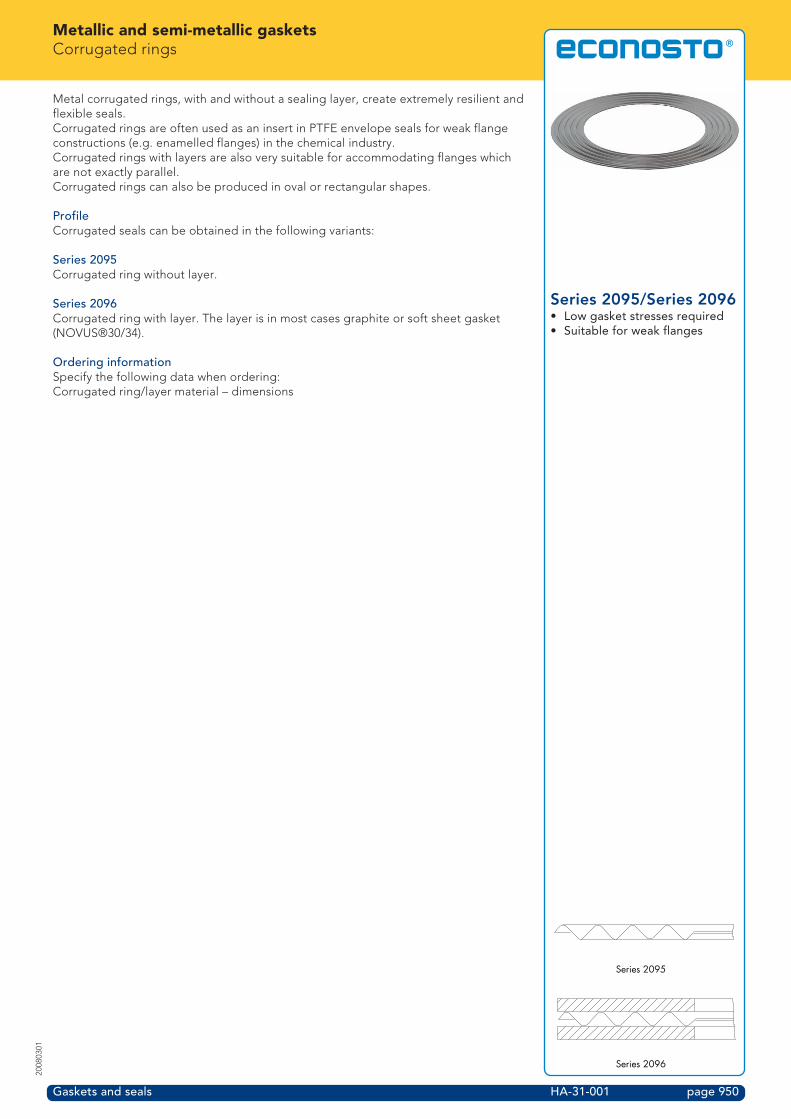
Series 2095/Series 2096• Low gasket stresses required• Suitable for weak flanges
Metal corrugated rings, with and without a sealing layer, create extremely resilient andflexible seals.Corrugated rings are often used as an insert in PTFE envelope seals for weak flangeconstructions (e.g. enamelled flanges) in the chemical industry.Corrugated rings with layers are also very suitable for accommodating flanges whichare not exactly parallel.Corrugated rings can also be produced in oval or rectangular shapes.
ProfileCorrugated seals can be obtained in the following variants:
Series 2095Corrugated ring without layer.
Series 2096Corrugated ring with layer. The layer is in most cases graphite or soft sheet gasket(NOVUS®30/34).
Ordering informationSpecify the following data when ordering:Corrugated ring/layer material – dimensions
Series 2095
Series 2096

Metallic and semi-metallic gasketsMetallic sealing ringsFlat, insert, lens, Delta and O-sealing rings
Gaskets and seals HA-32-001 page 951
2008
0301
Overview of metallicsealing rings• Series 2080• Series 2081• Series 2082• Series 2083• Series 2084• Series 2085
In addition to Ring Joint seals, a complete range of other solid metal seals is available;each has its own specific characteristics and areas of use.Besides the standardized shapes that are described below, problem-specific solutionsare also possible. Econosto can advise you in the choice or design of specific metallicseals.
Flat sealing ringsSeries 2080 (type M1)This type is used in such applications as for valves, seats, heat exchangers andscrewed connections.The dimensions comply with ISO 7483, DIN 7603A and DIN 16258.They can also be manufactured to comply with specifications from individualcustomers.
Insert ringsSeries 2081 (type M2)This machined sealing ring is available with or without a layer.These rings are used in Groove/Groove flange joints as per DIN 2512 and worksstandard WAS 100.
Lens ringsSeries 2082 (type M4)The sealing action is based on a line contact seal. A relatively low bolt tension alreadygives a good seal. This technique is applied on a large scale in high pressure pipesystems, from PN 64 to PN 400.The dimensions comply with DIN 2696 or are per customer specification.
O-ringsSeries 2083 (type M6)The O-rings are produced in welded or seamless versions. In general materials such asaluminium, copper and silver are used. After the production process the material isgenerally annealed. These rings are mainly used in gas and vacuum technology.The dimensions comply with the specifications from the customer.
Convex ringsSeries 2084 (type M10)The dimensions are DIN 7603D compliant or as per customer's specifications.
Delta gasketsSeries 2085 (type M15)Delta gaskets are produced within narrow tolerances.The gasket is designed in such a way that, due to the internal system pressure, it isself-energizing and because of this causes a high surface pressure between theflanges and the gasket. This gasket can be produced in all common materials. TheDelta gasket is used in applications such as pressure vessels.The dimensions comply with customer specifications.
Ordering informationSpecify the following data when ordering:Profile – material – dimension (standard)
Series 2080 (type M1)
Series 2081 (type M2)
Series 2082 (type M4)
Series 2083 (type M6)
Series 2084 (type M10)
Series 2085 (type M15)

Metallic and semi-metallic gasketsDimension table for flat and convex sealing rings
Gaskets and seals HA-33-001 page 952
2008
0301
Flat and convexsealing rings• Series 2080 (Type M1) flat ring• Series 2084 (Type M10) convex
rings• Standard DIN 7603 A and D
Nominal hdimension d1 d2 variant r
[mm] A D4 x 8 4.2 +0.3 7.9 -0.2 1 ±0,2 1 ±0,2 45 x 7.5 5.2 +0.3 7.4 -0.2 1 ±0,2 1 ±0,2 45.5 x 8 5.7 +0.3 7.9 -0.2 1 ±0,2 1 ±0,2 46.5 x 9.5 6.7 +0.3 9.4 -0.2 1 ±0,2 1 ±0,2 47 x 15 7.2 +0.3 14.9 -0.2 1.5 ±0,28 x 11.5 8.2 +0.3 11.4 -0.2 1 ±0,2 1 ±0,2 4
10 x 13.5 10.2 +0.3 13.4 -0.2 1 ±0,2 1 ±0,2 412 x 15.5 12.2 +0.3 15.4 -0.2 1.5 ±0,2 1.5 ±0,2 412 x 16 12.2 +0.3 15.9 -0.2 1.5 ±0,2 1.5 ±0,2 412 x 19 12.2 +0.3 18.9 -0.2 1.5 ±0,214 x 18 14.2 +0.3 17.9 -0.2 1.5 ±0,2 1.5 ±0,2 414 x 20 14.2 +0.3 19.9 -0.2 1.5 ±0,2 1.5 ±0,2 415 x 19 15.2 +0.3 18.9 -0.2 1.5 ±0,2 1.5 ±0,2 415 x 23 15.2 +0.3 22.9 -0.2 1.5 ±0,216 x 20 16.2 +0.3 19.9 -0.2 1.5 ±0,2 1.5 ±0,2 417 x 21 17.2 +0.3 20.9 -0.2 1.5 ±0,2 1.5 ±0,2 418 x 22 18.2 +0.3 21.9 -0.2 1.5 ±0,2 1.5 ±0,2 420 x 24 20.2 +0.3 23.9 -0.2 1.5 ±0,2 1.5 ±0,2 421 x 26 21.2 +0.3 25.9 -0.2 1.5 ±0,2 1.5 ±0,2 422 x 27 22.2 +0.3 26.9 -0.2 1.5 ±0,2 1.5 ±0,2 423 x 28 23.3 +0.3 27.9 -0.2 2 ±0,2 2 ±0,3 624 x 29 24.3 +0.3 28.9 -0.2 2 ±0,2 2 ±0,3 625 x 30 25.3 +0.3 29.9 -0.2 2 ±0,2 2 ±0,3 626 x 31 26.3 +0.3 30.9 -0.2 2 ±0,2 2 ±0,3 627 x 32 27.3 +0.3 31.9 -0.2 2 ±0,2 2 ±0,3 628 x 33 28.3 +0.3 32.9 -0.2 2 ±0,2 2 ±0,3 630 x 36 30.3 +0.3 35.9 -0.2 2 ±0,2 2 ±0,3 632 x 38 32.3 +0.3 37.9 -0.2 2 ±0,2 2 ±0,3 633 x 39 33.3 +0.3 38.9 -0.2 2 ±0,2 2 ±0,3 635 x 41 35.3 +0.3 40.9 -0.2 2 ±0,2 2 ±0,3 636 x 42 36.3 +0.3 41.9 -0.2 2 ±0,2 2 ±0,3 638 x 44 38.3 +0.3 43.9 -0.2 2 ±0,2 2 ±0,3 639 x 46 39.3 +0.3 45.9 -0.2 2 ±0,2 2 ±0,3 640 x 47 40.3 +0.3 46.9 -0.2 2 ±0,2 2 ±0,3 642 x 49 42.3 +0.3 48.9 -0.2 2 ±0,2 2 ±0,3 644 x 51 44.3 +0.3 50.9 -0.2 2 ±0,2 2 ±0,3 645 x 52 45.3 +0.3 51.9 -0.2 2 ±0,2 2 ±0,3 648 x 55 48.3 +0.3 54.9 -0.2 2 ±0,2 2 ±0,3 650 x 57 50.2 +0.3 56.9 -0.2 2 ±0,2 2 ±0,3 652 x 60 52.5 +0.5 59.8 -0.3 2.5 ±0,2 2.5 ±0,4 1054 x 62 54.5 +0.5 61.8 -0.3 2.5 ±0,2 2.5 ±0,4 1055 x 63 55.5 +0.5 62.8 -0.3 2.5 ±0,2 2.5 ±0,4 1056 x 64 56.5 +0.5 63.8 -0.3 2.5 ±0,2 2.5 ±0,4 1058 x 66 58.5 +0.5 65.8 -0.3 2.5 ±0,2 2.5 ±0,4 1060 x 68 60.5 +0.5 67.8 -0.3 2.5 ±0,2 2.5 ±0,4 1064 x 72 64.5 +0.5 71.8 -0.3 2.5 ±0,2 2.5 ±0,4 1065 x 74 65.5 +0.5 73.8 -0.3 2.5 ±0,2 2.5 ±0,4 1070 x 79 70.5 +0.5 78.8 -0.3 2.5 ±0,2 2.5 ±0,4 1075 x 84 75.5 +0.5 83.8 -0.3 2.5 ±0,2 2.5 ±0,4 1078 x 88 78.5 +0.5 87.8 -0.3 2.5 ±0,2 2.5 ±0,4 1080 x 90 80.7 +0.5 89.8 -0.3 2.5 ±0,2 2.5 ±0,4 1085 x 95 85.7 +0.5 94.8 -0.3 2.5 ±0,2 2.5 ±0,4 1090 x 100 90.7 +0.5 99.8 -0.3 2.5 ±0,2 2.5 ±0,4 10all dimensions in millimetres
d1d2
d1
d2
h
h

Metallic and semi-metallic gasketsDimension table for metal insert ringsFor DIN 2512 flanges
Gaskets and seals HA-34-001 page 953
2008
0301
Metal insert rings• Series 2081 (type M2)• For DIN 2512 flanges• PN 10-160• Groove/Groove
Nominal d1 d2 hpipe dimension
4-6 20 30 108 22 32 10
10 24 34 1015 29 39 1020 36 50 1025 43 57 1032 51 65 1040 61 75 1050 73 87 1065 95 109 1080 106 120 10
100 129 149 12125 155 175 12150 183 203 12175 213 233 12200 239 259 12250 292 312 12300 343 363 12350 395 421 14400 447 473 14500 549 575 14600 649 675 14700 751 777 14800 856 882 14900 961 987 14
1000 1062 1092 16all dimensions in millimetres
d1d2
h

Metallic and semi-metallic gasketsDimension table for metal insert ringsFor ASME B16.5 flanges
Gaskets and seals HA-35-001 page 954
2008
0301
Metal rings• Series 2081 (type M2)• For ASME B16.5• 150-2500Lbs• Groove/Groove• Works standard WAS100
Nominal d1 d2 hpipe dimension narrow wide
A 25 35 35 12C 33 43 43 12
1 38 48 51 121B 48 57 64 121A 54 64 73 122 73 83 92 122A 86 95 105 123 108 118 127 143A 121 130 140 144 132 145 157 145 160 173 186 146 190 203 216 148 238 254 270 14
10 286 305 324 1412 343 362 381 1414 375 394 413 1616 425 448 470 1618 489 511 535 1620 535 559 585 1622 591 616 641 1624 640 667 690 16all dimensions in millimetres
d1d2
h