METAL VAREA-METER STRAIGHT THROUGH TYPE ROTAMETER · 2011-06-02 · METAL VAREA-METER® STRAIGHT...
8
METAL VAREA-METER ® STRAIGHT THROUGH TYPE ROTAMETER U.S. Filter/Wallace & Tiernan Products straight through metal tube Varea-Meters are available in a variety of tube sizes and flange faces and ratings. These are suitable for harsh process conditions and are designed for the measurement of high volume flows of aggressive fluids and gases. They have high pressure and temperature limits and give reliable flow measurements over a 10:1 range. As a standard feature, a rugged, magnetically coupled flow indicator is provided. An optional flow transmitter is available to provide local indication as well as a mA output. TECHNICAL INFORMATION INTRODUCING THE METAL TUBE VAREA-METER FEATURES Anti-Magnetic-Particle Float The extra long float magnet has a reduced flux density and is located above the metering disk. This discourages accumulation of magnetic particles, specially on the disk edge where they can cause errors in indication. Meter design directs the flow into a pattern, which scrubs the float and guides clean. The Varea-Meter is ideal for suspensions and slurries. Electronic Transmitter
Transcript of METAL VAREA-METER STRAIGHT THROUGH TYPE ROTAMETER · 2011-06-02 · METAL VAREA-METER® STRAIGHT...

METAL VAREA-METER® STRAIGHT
THROUGH TYPE ROTAMETER
U.S. Filter/Wallace & Tiernan Products straight through metal tube Varea-Meters are
available in a variety of tube sizes and flange faces and ratings. These are suitable for
harsh process conditions and are designed for the measurement of high volume flows
of aggressive fluids and gases. They have high pressure and temperature limits and
give reliable flow measurements over a 10:1 range. As a standard feature, a rugged,
magnetically coupled flow indicator is provided. An optional flow transmitter
is available to provide local indication as well as a mA output.
TECHNICAL INFORMATION
INTRODUCING THE METAL TUBE VAREA-METER
FEATURES Anti-Magnetic-Particle FloatThe extra long float magnet has a reduced flux density and is located above the
metering disk. This discourages accumulation of magnetic particles, specially on
the disk edge where they can cause errors in indication. Meter design directs the
flow into a pattern, which scrubs the float and guides clean. The Varea-Meter is
ideal for suspensions and slurries.
Electronic Transmitter
FEATURES
2
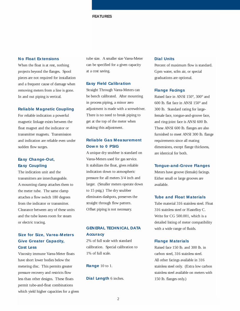
No Float ExtensionsWhen the float is at rest, nothing
projects beyond the flanges. Spool
pieces are not required for installation
and a frequent cause of damage when
removing meters from a line is gone.
In and out piping is vertical.
Reliable Magnetic CouplingFor reliable indication a powerful
magnetic linkage exists between the
float magnet and the indicator or
transmitter magnets. Transmission
and indication are reliable even under
sudden flow surges.
Easy Change-Out, Easy CouplingThe indication unit and the
transmitters are interchangeable.
A mounting clamp attaches them to
the meter tube. The same clamp
attaches a flow switch 180 degrees
from the indicator or transmitter.
Clearance between any of these units
and the tube leaves room for steam
or electric tracing.
Size for Size, Varea-MetersGive Greater Capacity, Cost LessViscosity immune Varea-Meter floats
have short lower bodies below the
metering disc. This permits greater
pressure recovery and restricts flow
less than other designs. These floats
permit tube-and-float combinations
which yield higher capacities for a given
tube size. A smaller size Varea-Meter
can be specified for a given capacity
at a cost saving.
Easy Field CalibrationStraight Through Varea-Meters can
be bench calibrated. After mounting
in process piping, a minor zero
adjustment is made with a screwdriver.
There is no need to break piping to
get at the top of the meter when
making this adjustment.
Reliable Gas MeasurementDown to 0 PSIGA unique dry snubber is standard on
Varea-Meters used for gas service.
It stabilizes the float, gives reliable
indication down to atmospheric
pressure for all meters 3/4 inch and
larger. (Smaller meters operate down
to 15 psig.) The dry snubber
eliminates dashpots, preserves the
straight through flow pattern.
Offset piping is not necessary.
GENERAL TECHNICAL DATAAccuracy2% of full scale with standard
calibration. Special calibration to
1% of full scale.
Range 10 to 1.
Dial Length 6 inches.
Dial UnitsPercent of maximum flow is standard.
Gpm water, scfm air, or special
graduations are optional.
Flange FacingsRaised face in ANSI 150°, 300° and
600 lb. flat face in ANSI 150° and
300 lb. Standard rating for large-
female face, tongue-and-groove face,
and ring-joint face is ANSI 600 lb.
These ANSI 600 lb. flanges are also
furnished to meet ANSI 300 lb. flange
requirements since all mating
dimensions, except flange thickness,
are identical for both.
Tongue-and-Grove FlangesMeters have groove (female) facings.
Either small or large grooves are
available.
Tube and Float MaterialsTube material 316 stainless steel. Float
316 stainless steel or Hastelloy C.
Write for CG 500.001, which is a
detailed listing of meter compatibility
with a wide range of fluids.
Flange MaterialsRaised face 150 lb. and 300 lb. in
carbon steel, 316 stainless steel.
All other facings available in 316
stainless steel only. (Extra low carbon
stainless steel available on meters with
150 lb. flanges only.)

3
SELECTION PROCEDURE FOR LIQUID SERVICEDetermine the capacity range, temperature and pressure
capability, materials of construction, and options required
for each meter.
From chemical supplier determine float material. If the
liquid is other than water, the desired units are other than
GPM, its flow rate must be converted to GPM water
(equivalent Flow Rate).
How to Determine Water EquivalentFor liquids with viscosities greater than the viscosity ceiling,
Consult Distributor. For liquids with specific gravity other
than 1.0 follow the Formula to determine Equivalent Flow Rate
in GPM (QE).
Equivalent Desired CorrectionFlow Rate Flow Rate Factors
QE GPM QD FE X FU
1. From Table A determine FE from Specific
Gravity Correction factors.
2. From Table B determine FU from
Unit Conversation factors.
3. Work Formula to obtain Equivalent
Flow Rate (QE).
4. Use Equivalent Flow Rate to select tube
and float code from Table C on page 5.
=
=
X
X
SELECTION PROCEDURE

4
SELECTION PROCEDURE FOR GAS SERVICEDetermine the capacity range, temperature and
pressure capability, materials of construction, and
options required for each meter.
From chemical supplier determine float material.
Table C capacities, are air SCFM at 14.7 PSIA & 70ºF.
If the gas is other than the above, its flow rate must
be converted to SCFM air (Equivalent Flow Rate)
How to Determine Air Equivalent1. From Table A select appropriate Formula to
determine Equivalent Flow Rate (QE).
2. From Table B determine FG from Specific
Gravity Correction factors.
3. From Table D determine FP from
Pressure Correction factors.
4. From Table E determine FT from
Temperature Correction factors.
5. From Table F determine FU from
Unit Conversion factors.
6. Work Formula to obtain Equivalent Flow Rate (QE)
7. Use Equivalent Flow Rate to select tube and float
code from Table C on page 5.
SELECTION PROCEDURE
5
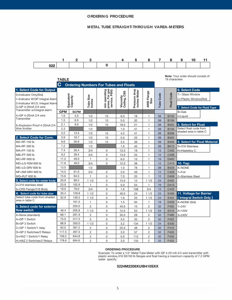
ORDERING PROCEDURE
METAL TUBE STRAIGHT-THROUGH VAREA-METERS
6
TECHNICAL DATA
TEMPERATURE-PRESSURERATINGSWith 150 lb. ANSI flanges, all tube sizes:
230 psi at 0°F to 140 psi at 600°F
With 300 lb. ANSI flanges, all tube sizes:
600 psi at 0°F to 360 psi at 600°F
With 600 lb. ANSI flanges, 2-inch tube:
960 psi at 0°F to 620 psi at 600°F
With 600 lb. ANSI flanges, 11/2 inch
tube:
1200 psi at 0°F to 720 psi at 600°F
With 600 lb. ANSI flanges, 1/2, 3/4,
or 1 in. tube:
1200 psi at 0°F to 720 psi at 600°F
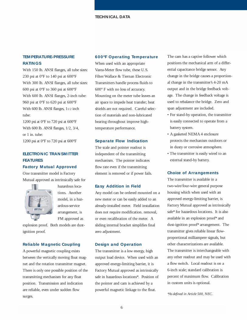
ELECTRONIC TRANSMITTERFEATURES Factory Mutual ApprovedOne transmitter model is Factory
Mutual approved as intrinsically safe for
hazardous loca-
tions. Another
model, in a haz-
ardous-service
arrangement, is
FM approved as
explosion proof. Both models are dust-
ignition proof.
Reliable Magnetic CouplingA powerful magnetic coupling exists
between the vertically moving float mag-
net and the rotation transmitter magnet.
There is only one possible position of the
transmitting mechanism for any float
position. Transmission and indication
are reliable, even under sudden flow
surges.
600ºF Operating TemperatureWhen used with an appropriate
Varea-Meter flow tube, these U.S.
Filter/Wallace & Tiernan Electronic
Transmitters handle process fluids to
600° F with no loss of accuracy.
Mounting on the meter tube leaves an
air space to impede heat transfer; heat
shields are not required. Careful selec-
tion of materials and non-lubricated
bearing throughout improve high-
temperature performance.
Separate Flow IndicationThe scale and pointer readout is
independent of the transmitting
mechanism. The pointer indicates
flow rate even if the transmitting
element is removed or if power fails.
Easy Addition in FieldAny model can be ordered mounted on a
new meter or can be easily added to an
already-installed meter. Field installation
does not require modification. removal,
or even recalibration of the meter. A
sliding internal bracket simplifies final
zero adjustment.
Design and OperationThe transmitter is a low energy, high
output load device. When used with an
approved energy-limiting barrier, it is
Factory Mutual approved as intrinsically
safe in hazardous locations*. Position of
the pointer and cam is achieved by a
powerful magnetic linkage to the float.
The cam has a captive follower which
positions the mechanical arm of a differ-
ential capacitance bridge sensor. Any
change in the bridge causes a proportion-
al change in the transmitter’s 4-20 mA
output and in the bridge feedback volt-
age. The change in feedback voltage is
used to rebalance the bridge. Zero and
span adjustment are included.
• For stand-by operation, the transmitter
is easily connected to operate from a
battery system.
• A gasketed NEMA 4 enclosure
protects the mechanism outdoors or
in dusty or corrosive atmosphere.
• The transmitter is easily wired to an
external stand-by battery.
Choice of ArrangementsThe transmitter is available in a
two-wire/four-wire general purpose
housing which when used with an
approved energy-limiting barrier, is
Factory Mutual approved as intrinsically
safe* for hazardous locations. It is also
available in an explosion proof* and
dust-ignition proof* arrangement. The
transmitter gives reliable linear flow-
proportional milliampere signals, but
other characterizations are available.
The transmitter is interchangeable with
any other readout and may be used with
a flow switch. Local readout is on a
6-inch scale; standard calibration is
percent of maximum flow. Calibration
in custom units is optional.
*As defined in Article 500, NEC.

7
TECHNICAL DATA
AccuracyCombined meter and transmitter accura-
cy is 2% of full scale (1% with custom
calibration).
Sensitivity 0.2% of full scale.
Linearity 0.4% of full scale.
Repeatability 0.3% of full scale.
Operating Range 10 to 1.
Speed of ResponseComplete response to a flow-rate change
from 10% to 90% of full scale in 0.5
seconds.
Output Signals4-20 mA dc flow proportional.
Electrical RequirementsAvailable from U.S. Filter/Wallace &
Tiernan are: a 24 VDC supply for
general purpose, intrinsically safe (with
the appropriate electronic barriers), and
explosion proof arrangements. Current
Consumption: 5 mA signal current.
Allowable Loop Resistance0 ohms for 12 VDC supply, 500 ohms
for a 22 VDC supply (maximum allow-
able for intrinsically safe operation); 600
ohms for a 24 VDC supply; 900 ohms
for a 33 VDC supply.
Output Load EffectOutput independent of load.
Temperature RangeMaximum fluid temperature is 600°F;
ambient range is –13 to 140°F.
Temperature EffectOutput changes less than 0.036%
of full scale per degree F change
from – 13°F to 140°F.
Electrical ClassificationGeneral Purpose Enclosure: In NEMA 4
general purpose enclosure the transmitter
is Factory Mutual approved as intrinsi-
cally safe for Class I, Division 1, Group
A, B, C, and D hazardous locations
when installed according to instruction
book drawing 520.209.110.011.
FM entity parameters: Vmax = 30V;
Imax = 160 mA; Ci < 10 nF; Li =
50u H.
Examples of electronic barriers acceptable
under the entity system are:
Pepperl & Fuchs transmitter converter
KMD 2-cr-1.P.30300 or Zener barrier
#Z728 or Z828; MTL #706 + 20 and
FM approved as dust-ignition proof for
Class II, Division 1 and 2, Group E and
G and suitable for Class III, Division 1.
Optional Explosion proof Arrangement:
As an explosion proof arrangement, the
transmitter is FM approved as explosion
proof for Class I, Division 1, Group A,
B, C, and D hazardous locations; and
FM approved as dust-ignition proof for
Class II, Division 1, Group E, F and G
hazardous locations; suitable for Class
III, Division 1.
ConnectionsEnclosed 1/2" conduit connection.
Transmitter to receiver, unshielded wires.
FLOW SWITCHChoice of Two External AlarmsThis compact option gives reliable high
and /or low flow switching. The U.S.
Filter/Wallace & Tiernan Flow Switch
contains a powerful
rotating magnet
which responds lin-
early to float posi-
tion. Its switches
are long life, her-
metically sealed reed types. Almost
frictionless rotation of the switch magnet
and its powerful bond with the float
magnet give a dependable magnetic cou-
pling. Even under sudden flow surges
switching remains reliable. The switch is
available in a UL listed, hazardous loca-
tion* arrangement (Series 5500) and a
general purpose arrangement (Series
5600) in NEMA 4 enclosure.
Easily added in the field with the meter
in the line. No extension rod, on inter-
ference with vertical piping. Can set
switches to open or close on increasing
or decreasing flow. In the general pur-
pose model, this is done without remov-
ing the cover. A screwdriver adjustment
sets each switch independently over 0 to
100% of the flow range.
*As defined in Article 500, NEC.