METAL PIPE ARCH CULVERT - The Office of Federal Lands · PDF file ·...
18
NO SCALE 4. 3. 2. 1. METAL ROUND PIPE CULVERT METAL PIPE ARCH CULVERT FILL HEIGHT AND METAL THICKNESS TABLE FOR HELICAL LOCKSEAM AND WELDED SEAM PIPE CULVERT FILL HEIGHT AND METAL THICKNESS TABLE FOR HELICAL LOCKSEAM AND WELDED SEAM PIPE CULVERT STEEL ALUMINUM DIAMETER VALENT EQUI- RADIUS CORNER MINIMUM COVER MINIMUM SPAN x RISE SIZE PIPE ARCH SIZE PIPE ARCH SPAN x RISE DIAMETER VALENT EQUI- RADIUS CORNER MINIMUM COVER MINIMUM COVER MINIMUM DIAMETER SIZE PIPE SIZE PIPE DIAMETER COVER MINIMUM ALUMINUM STEEL of camber or increase the pipe culvert gradient. elevation of the inlet invert, reduce the amount parabolic curve as designed exceeds the curve. If the midpoint elevation on the pipe length. Develop camber on a parabolic inverts an ordinate amount equal to 1% of the from a chord through the inlet and outlet When directed, camber pipe culverts upward pavement for both flexible and rigid pavement. from the top of the pipe to the top of the rigid pavements. Measure maximum fill height pavements, and to the top of the pavement for pipe culvert to the subgrade for flexible Measure minimum cover from the top of the corrugation pipe. Obtain approval before furnishing annular of helical lockseam and welded seam pipe. corrugations are more restrictive than those Fill heights for culvert pipe with annular lockseam and welded seam pipe only. The fill heights in the table are for helical special analysis by the CO. 602-1 STANDARD APPROVED FOR USE 12/1993 REVISED: 4/1994 6/2005 METAL PIPE CULVERT STATE PROJECT NUMBER SHEET U.S. DEPARTMENT OF TRANSPORTATION FEDERAL HIGHWAY ADMINISTRATION 3 46 P M 24 Augu s t2015 ] USC [ c :\ m y f il e s \ p w_p r odu c ti on \ d m s 52075 \ St d602 - 1 . dgn FEDERAL LANDS HIGHWAY U.S. CUSTOMARY STANDARD STANDARD Fill heights exceeding 100 feet require " CORRUGATIONS 2 1 " x 3 2 2 3" x 1" CORRUGATIONS METAL THICKNESS (INCH/GAGE) 0.060/16 0.075/14 0.105/12 0.135/10 0.164/8 0.060/16 0.075/14 0.105/12 0.135/10 0.164/8 MAXIMUM FILL HEIGHT ABOVE TOP OF PIPE (FEET) INCHES INCHES 120 114 108 102 96 90 84 78 72 66 60 54 48 42 36 30 24 21 18 15 12 24 24 24 24 24 24 24 24 18 18 18 18 12 12 12 12 12 12 12 12 12 44 52 62 77 88 100 100 100 55 64 77 97 100 100 100 100 54 67 77 90 100 100 100 100 100 100 57 71 87 99 100 100 100 100 100 100 100 45 58 72 88 100 100 100 100 100 100 100 100 100 30 32 35 39 44 51 59 71 34 37 40 45 50 56 64 74 89 38 41 44 48 55 56 62 69 78 89 100 100 42 46 51 62 59 64 70 76 83 93 100 100 100 100 40 45 50 55 61 65 70 75 82 89 98 100 100 100 100 100 " CORRUGATIONS 2 1 " x 3 2 2 3" x 1" CORRUGATIONS 5" x 1" CORRUGATIONS METAL THICKNESS (INCH/GAGE) 0.064/16 0.079/14 0.109/12 0.138/10 0.168/8 0.064/16 0.079/14 0.109/12 0.138/10 0.168/8 0.064/16 0.079/14 0.109/12 0.138/10 0.168/8 MAXIMUM FILL HEIGHT ABOVE TOP OF PIPE (FEET) INCHES 18 18 18 18 18 18 18 18 12 12 12 12 12 12 12 12 12 12 12 12 12 12 12 12 12 53 61 71 85 100 100 100 100 100 59 66 76 89 100 100 100 100 100 100 74 83 93 100 100 100 100 100 100 100 100 80 87 97 100 100 100 100 100 100 100 100 100 100 75 87 97 100 100 100 100 100 100 100 100 100 100 100 100 32 35 37 40 44 49 54 61 70 81 36 38 40 43 47 51 55 61 68 76 87 100 43 45 47 50 53 57 61 66 71 78 86 95 100 100 100 48 50 52 55 58 61 65 69 73 78 85 92 100 100 100 100 100 100 56 58 61 64 67 71 75 79 84 90 96 100 100 100 100 100 100 100 100 29 31 33 36 39 43 48 54 32 34 36 39 42 45 49 54 60 68 38 40 42 45 48 51 54 58 63 69 76 85 95 42 44 47 49 52 54 57 61 65 70 75 82 89 98 100 100 50 52 54 57 60 63 67 71 75 80 86 92 100 100 100 100 100 INCHES 144 138 132 126 120 114 108 102 96 90 84 78 72 66 60 54 48 42 36 30 24 21 18 15 12 INCHES 142 x 91 137 x 87 128 x 83 117 x 79 112 x 75 103 x 71 95 x 67 87 x 63 83 x 57 81 x 59 77 x 52 73 x 55 71 x 47 66 x 51 64 x 43 60 x 46 57 x 38 49 x 33 42 x 29 35 x 24 28 x 20 24 x 18 21 x 15 17 x 13 INCHES 120 114 108 102 96 90 84 78 72 72 66 66 60 60 54 54 48 42 36 30 24 21 18 15 INCHES 18 18 18 18 18 16 16 14 9 14 8 12 7 9 6 8 5 4 3.5 3 3 3 3 3 INCHES 24 24 24 21 21 18 18 18 12 18 12 18 12 15 12 15 12 12 12 12 12 12 12 12 " CORRUGATIONS 2 1 " x 3 2 2 3" x 1" CORRUGATIONS METAL THICKNESS (INCH/GAGE) 5" x 1" CORRUGATIONS 0.064/16 0.079/14 0.109/12 0.138/10 0.168/8 0.079/14 0.109/12 0.138/10 0.168/8 0.079/14 MAXIMUM FILL HEIGHT ABOVE TOP OF PIPE (FEET) 12 12 13 13 12 13 12 12 12 12 16 16 17 20 21 21 12 12 17 17 17 16 16 20 21 21 17 17 17 17 16 16 16 16 16 16 0.109/12 0.138/10 0.168/8 INCHES INCHES INCHES 103 x 71 95 x 67 87 x 63 81 x 59 73 x 55 66 x 51 64 x 43 60 x 46 57 x 38 49 x 33 42 x 29 35 x 24 28 x 20 24 x 18 21 x 15 17 x 13 90 84 78 72 66 60 54 54 48 42 36 30 24 21 18 15 INCHES 24 24 21 21 18 18 18 15 15 15 15 12 12 12 12 12 16 16 14 14 12 9 6 8 5 4 3.5 3 3 3 3 3 13 12 13 12 13 12 12 " CORRUGATIONS 2 1 " x 3 2 2 METAL THICKNESS (INCH/GAGE) 3" x 1" CORRUGATIONS 0.135/10 0.105/12 0.075/14 MAXIMUM FILL HEIGHT ABOVE TOP OF PIPE (FEET) 0.060/16 0.135/10 0.105/12 0.075/14 0.060/16 12 12 21 21 20 17 17 17 17 NOTE:
Transcript of METAL PIPE ARCH CULVERT - The Office of Federal Lands · PDF file ·...
NO SCALE
4.
3.
2.
1.
METAL ROUND PIPE CULVERT
METAL PIPE ARCH CULVERT
FILL HEIGHT AND METAL THICKNESS TABLE FOR HELICAL LOCKSEAM AND WELDED SEAM PIPE CULVERT
FILL HEIGHT AND METAL THICKNESS TABLE FOR HELICAL LOCKSEAM AND WELDED SEAM PIPE CULVERT
STEEL ALUMINUM
DIAMETER
VALENT
EQUI-
RADIUS
CORNER
MINIMUM
COVER
MINIMUMSPAN x RISE
SIZE
PIPE ARCH
SIZE
PIPE ARCH
SPAN x RISE DIAMETER
VALENT
EQUI-
RADIUS
CORNER
MINIMUM
COVER
MINIMUM
COVER
MINIMUM
DIAMETER
SIZE
PIPE
SIZE
PIPE
DIAMETER COVER
MINIMUM
ALUMINUMSTEEL
of camber or increase the pipe culvert gradient.
elevation of the inlet invert, reduce the amount
parabolic curve as designed exceeds the
curve. If the midpoint elevation on the
pipe length. Develop camber on a parabolic
inverts an ordinate amount equal to 1% of the
from a chord through the inlet and outlet
When directed, camber pipe culverts upward
pavement for both flexible and rigid pavement.
from the top of the pipe to the top of the
rigid pavements. Measure maximum fill height
pavements, and to the top of the pavement for
pipe culvert to the subgrade for flexible
Measure minimum cover from the top of the
corrugation pipe.
Obtain approval before furnishing annular
of helical lockseam and welded seam pipe.
corrugations are more restrictive than those
Fill heights for culvert pipe with annular
lockseam and welded seam pipe only.
The fill heights in the table are for helical
special analysis by the CO.
602-1
STANDARD APPROVED FOR USE 12/1993
REVISED: 4/1994 6/2005
METAL PIPE CULVERT
STATE PROJECTNUMBER
SHEET
U.S. DEPARTMENT OF TRANSPORTATION
FEDERAL HIGHWAY ADMINISTRATION
3:46 P
M
24 A
ugust
2015
]U
SC
[
c:\m
yfiles\p
w_production\d
ms52075\Std
602-1.d
gn
FEDERAL LANDS HIGHWAY
U.S. CUSTOMARY STANDARD
STANDARD
Fill heights exceeding 100 feet require
" CORRUGATIONS21" x 3
22 3" x 1" CORRUGATIONS
METAL THICKNESS (INCH/GAGE)
0.060/160.075/140.105/120.135/10 0.164/8 0.060/160.075/140.105/120.135/10 0.164/8
MAXIMUM FILL HEIGHT ABOVE TOP OF PIPE (FEET)INCHES INCHES
120
114
108
102
96
90
84
78
72
66
60
54
48
42
36
30
24
21
18
15
12
24
24
24
24
24
24
24
24
18
18
18
18
12
12
12
12
12
12
12
12
12
44
52
62
77
88
100
100
100
55
64
77
97
100
100
100
100
54
67
77
90
100
100
100
100
100
100
57
71
87
99
100
100
100
100
100
100
100
45
58
72
88
100
100
100
100
100
100
100
100
100
30
32
35
39
44
51
59
71
34
37
40
45
50
56
64
74
89
38
41
44
48
55
56
62
69
78
89
100
100
42
46
51
62
59
64
70
76
83
93
100
100
100
100
40
45
50
55
61
65
70
75
82
89
98
100
100
100
100
100
" CORRUGATIONS21" x 3
22 3" x 1" CORRUGATIONS 5" x 1" CORRUGATIONS
METAL THICKNESS (INCH/GAGE)
0.064/160.079/140.109/120.138/10 0.168/8 0.064/160.079/140.109/120.138/10 0.168/8 0.064/160.079/140.109/120.138/10 0.168/8
MAXIMUM FILL HEIGHT ABOVE TOP OF PIPE (FEET)INCHES
18
18
18
18
18
18
18
18
12
12
12
12
12
12
12
12
12
12
12
12
12
12
12
12
12
53
61
71
85
100
100
100
100
100
59
66
76
89
100
100
100
100
100
100
74
83
93
100
100
100
100
100
100
100
100
80
87
97
100
100
100
100
100
100
100
100
100
100
75
87
97
100
100
100
100
100
100
100
100
100
100
100
100
32
35
37
40
44
49
54
61
70
81
36
38
40
43
47
51
55
61
68
76
87
100
43
45
47
50
53
57
61
66
71
78
86
95
100
100
100
48
50
52
55
58
61
65
69
73
78
85
92
100
100
100
100
100
100
56
58
61
64
67
71
75
79
84
90
96
100
100
100
100
100
100
100
100
29
31
33
36
39
43
48
54
32
34
36
39
42
45
49
54
60
68
38
40
42
45
48
51
54
58
63
69
76
85
95
42
44
47
49
52
54
57
61
65
70
75
82
89
98
100
100
50
52
54
57
60
63
67
71
75
80
86
92
100
100
100
100
100
INCHES
144
138
132
126
120
114
108
102
96
90
84
78
72
66
60
54
48
42
36
30
24
21
18
15
12
INCHES
142 x 91
137 x 87
128 x 83
117 x 79
112 x 75
103 x 71
95 x 67
87 x 63
83 x 57
81 x 59
77 x 52
73 x 55
71 x 47
66 x 51
64 x 43
60 x 46
57 x 38
49 x 33
42 x 29
35 x 24
28 x 20
24 x 18
21 x 15
17 x 13
INCHES
120
114
108
102
96
90
84
78
72
72
66
66
60
60
54
54
48
42
36
30
24
21
18
15
INCHES
18
18
18
18
18
16
16
14
9
14
8
12
7
9
6
8
5
4
3.5
3
3
3
3
3
INCHES
24
24
24
21
21
18
18
18
12
18
12
18
12
15
12
15
12
12
12
12
12
12
12
12
" CORRUGATIONS21" x 3
22 3" x 1" CORRUGATIONS
METAL THICKNESS (INCH/GAGE)
5" x 1" CORRUGATIONS
0.064/160.079/140.109/120.138/10 0.168/8 0.079/140.109/120.138/10 0.168/8 0.079/14
MAXIMUM FILL HEIGHT ABOVE TOP OF PIPE (FEET)
12
12
13
13
12
13
12
12
12
12
16
16
17
20
21
21
12
12
17
17
17
16
16
20
21
21
17
17
17
17
16
16
16
16
16
16
0.109/120.138/10 0.168/8
INCHES INCHES INCHES
103 x 71
95 x 67
87 x 63
81 x 59
73 x 55
66 x 51
64 x 43
60 x 46
57 x 38
49 x 33
42 x 29
35 x 24
28 x 20
24 x 18
21 x 15
17 x 13
90
84
78
72
66
60
54
54
48
42
36
30
24
21
18
15
INCHES
24
24
21
21
18
18
18
15
15
15
15
12
12
12
12
12
16
16
14
14
12
9
6
8
5
4
3.5
3
3
3
3
3
13
12
13
12
13
12
12
" CORRUGATIONS21" x 3
22
METAL THICKNESS (INCH/GAGE)
3" x 1" CORRUGATIONS
0.135/100.105/120.075/14
MAXIMUM FILL HEIGHT ABOVE TOP OF PIPE (FEET)
0.060/160.135/100.105/120.075/140.060/16
12
12
21
21
20
17
17
17
17
NOTE:

NO SCALE
4.
3.
2.
1.
METAL ROUND PIPE CULVERT
METAL PIPE ARCH CULVERT
FILL HEIGHT AND METAL THICKNESS TABLE FOR HELICAL LOCKSEAM AND WELDED SEAM PIPE CULVERT
FILL HEIGHT AND METAL THICKNESS TABLE FOR HELICAL LOCKSEAM AND WELDED SEAM PIPE CULVERT
STEEL ALUMINUM
DIAMETER
VALENT
EQUI-
RADIUS
CORNER
MINIMUM
COVER
MINIMUMSPAN x RISE
SIZE
PIPE ARCH
SIZE
PIPE ARCH
SPAN x RISE DIAMETER
VALENT
EQUI-
RADIUS
CORNER
MINIMUM
COVER
MINIMUM
COVER
MINIMUM
DIAMETER
SIZE
PIPE
SIZE
PIPE
DIAMETER COVER
MINIMUM
ALUMINUMSTEEL
of camber or increase the pipe culvert gradient.
elevation of the inlet invert, reduce the amount
parabolic curve as designed exceeds the
curve. If the midpoint elevation on the
pipe length. Develop camber on a parabolic
inverts an ordinate amount equal to 1% of the
from a chord through the inlet and outlet
When directed, camber pipe culverts upward
pavement for both flexible and rigid pavement.
from the top of the pipe to the top of the
rigid pavements. Measure maximum fill height
pavements, and to the top of the pavement for
pipe culvert to the subgrade for flexible
Measure minimum cover from the top of the
corrugation pipe.
Obtain approval before furnishing annular
of helical lockseam and welded seam pipe.
corrugations are more restrictive than those
Fill heights for culvert pipe with annular
lockseam and welded seam pipe only.
The fill heights in the table are for helical
special analysis by the CO.
STANDARD APPROVED FOR USE 3/1996
REVISED: 10/1997 6/2005
METAL PIPE CULVERT
602-1M
STATE PROJECTNUMBER
SHEET
U.S. DEPARTMENT OF TRANSPORTATION
FEDERAL HIGHWAY ADMINISTRATION
]M
etric
[
c:\m
yfiles\p
w_production\d
ms52075\Std
602-1.d
gn
3:46 P
M
24 A
ugust
2015
FEDERAL LANDS HIGHWAY
STANDARD
METRIC STANDARD
Fill heights exceeding 30 meters require
Dimensions without units are millimeters.5.
68 x 13 CORRUGATIONS 75 x 25 CORRUGATIONS
METAL THICKNESS
125 x 25 CORRUGATIONS
450
450
450
450
450
450
450
450
300
300
300
300
300
300
300
300
300
300
300
300
300
300
300
300
300
3600
3450
3300
3150
3000
2850
2700
2550
2400
2250
2100
1950
1800
1650
1500
1350
1200
1050
900
750
600
525
450
375
300
1.63 2.01 2.77 3.51 4.27 1.63 2.01 2.77 3.51 4.27 1.63 2.01 2.77 3.51 4.27
MAXIMUM FILL HEIGHT ABOVE TOP OF PIPE (METERS)
16.2
18.5
21.6
25.9
30.0
30.0
30.0
30.0
30.0
18.0
20.2
23.1
27.0
30.0
30.0
30.0
30.0
30.0
30.0
22.7
25.2
28.4
30.0
30.0
30.0
30.0
30.0
30.0
30.0
30.0
24.3
26.5
29.5
30.0
30.0
30.0
30.0
30.0
30.0
30.0
30.0
30.0
30.0
22.8
26.4
29.7
30.0
30.0
30.0
30.0
30.0
30.0
30.0
30.0
30.0
30.0
30.0
30.0
9.8
10.6
11.4
12.3
13.5
14.8
16.5
18.5
21.2
24.8
10.9
11.6
12.3
13.2
14.3
15.4
16.9
18.6
20.6
23.2
26.6
30.0
13.0
13.7
14.4
15.3
16.2
17.3
18.6
20.0
21.7
23.7
26.1
29.0
30.0
30.0
30.0
14.5
15.2
15.9
16.7
17.6
18.6
19.7
20.9
22.3
23.9
25.8
28.0
30.0
30.0
30.0
30.0
30.0
30.0
17.1
17.8
18.6
19.5
20.5
21.6
22.8
24.1
25.7
27.4
29.3
30.0
30.0
30.0
30.0
30.0
30.0
30.0
30.0
8.8
9.4
10.1
11.0
12.0
13.2
14.7
16.5
9.7
10.3
11.0
11.8
12.7
13.8
15.0
16.5
18.4
20.7
11.6
12.2
12.8
13.6
14.5
15.4
16.5
17.8
19.3
21.1
23.2
25.8
29.0
12.9
13.5
14.2
14.9
15.7
16.6
17.5
18.6
19.9
21.3
23.0
24.9
27.1
29.9
30.0
30.0
15.2
15.8
16.6
17.4
18.2
19.2
20.3
21.5
22.8
24.3
26.1
28.1
30.0
30.0
30.0
30.0
30.0
3000
2850
2700
2550
2400
2250
2100
1950
1800
1650
1500
1350
1200
1050
900
750
600
525
450
375
300
600
600
600
600
600
600
600
600
450
450
450
450
300
300
300
300
300
300
300
300
300
13.4
15.7
18.8
23.6
26.9
30.0
30.0
30.0
16.8
19.6
23.6
29.5
30.0
30.0
30.0
30.0
16.5
20.3
23.6
27.5
30.0
30.0
30.0
30.0
30.0
30.0
68 x 13 CORRUGATIONS
1.52 1.91 2.67
MAXIMUM FILL HEIGHT ABOVE TOP OF PIPE (METERS)
3.43
METAL THICKNESS
75 x 25 CORRUGATIONS
4.17 1.52 1.91
17.5
21.6
26.4
30.3
30.0
30.0
30.0
30.0
30.0
30.0
30.0
13.8
17.6
21.8
26.7
30.0
30.0
30.0
30.0
30.0
30.0
30.0
30.0
30.0
2.67 3.43 4.17
12.2
13.6
15.1
16.7
18.5
19.9
21.4
23.0
24.9
27.2
29.9
30.0
30.0
30.0
30.0
30.0
12.7
14.1
15.6
18.9
18.1
19.5
21.2
23.1
25.4
28.2
30.0
30.0
30.0
30.0
11.6
12.6
13.5
14.6
16.8
17.2
19.0
21.1
23.7
27.1
30.0
30.0
10.4
11.3
12.3
13.6
15.1
17.0
19.4
22.7
27.2
9.0
9.8
10.8
12.0
13.5
15.5
18.0
21.7
3610 x 2310
3480 x 2210
3250 x 2110
2970 x 2010
2840 x 1910
2620 x 1800
2410 x 1700
2210 x 1600
2110 x 1450
2060 x 1500
1960 x 1320
1850 x 1400
1800 x 1190
1680 x 1300
1630 x 1090
1520 x 1170
1450 x 970
1240 x 840
1070 x 740
890 x 610
710 x 510
610 x 460
530 x 380
430 x 330
3000
2850
2700
2550
2400
2250
2100
1950
1800
1800
1650
1650
1500
1500
1350
1350
1200
1050
900
750
600
525
450
375
455
455
455
455
455
405
405
355
230
355
205
305
180
230
150
205
125
100
90
75
75
75
75
75
600
600
600
525
525
450
450
450
300
450
300
450
300
375
300
375
300
300
300
300
300
300
300
300
68 x 13 CORRUGATIONS 75 x 25 CORRUGATIONS 125 x 25 CORRUGATIONS
METAL THICKNESS
1.63 2.01 2.77 3.51 4.27 2.01 2.77 3.51 4.27 2.01 2.77 3.51 4.27
3.7
3.7
4.0
4.0
3.7
4.0
MAXIMUM FILL HEIGHT ABOVE TOP OF PIPE (METERS)
3.7
3.7
5.2
5.2
5.2
4.9
4.9
5.2
6.1
6.4
6.4
3.7
3.7
4.9
4.9
6.1
6.4
6.4
5.2
5.2
5.2
5.2
2620 x 1800
2410 x 1700
2210 x 1600
2060 x 1500
1850 x 1400
1680 x 1300
1630 x 1090
1520 x 1170
1450 x 970
1240 x 840
1070 x 740
890 x 610
710 x 510
610 x 460
530 x 380
430 x 330
2250
2100
1950
1800
1650
1500
1350
1350
1200
1050
900
750
600
525
450
375
405
405
355
355
305
230
150
205
125
100
90
75
75
75
75
75
600
600
525
525
450
450
450
375
375
375
375
300
300
300
300
300
68 x 13 CORRUGATIONS
METAL THICKNESS
1.52 1.91 2.67 3.43
MAXIMUM FILL HEIGHT ABOVE TOP OF PIPE (METERS)
4.0
3.7
4.0
75 x 25 CORRUGATIONS
1.52 1.91 2.67 3.43
3.7
4.0
3.7
3.7
3.7
3.7
6.4
6.4
6.1
5.2
5.2
5.2
5.2
4.9
4.9
4.9
4.9
4.9
4.9
3.7
3.7
NOTE:

NO SCALE
2.
1.
SMOOTH SLEEVE BAND FLAT BAND
SEMI-CORRUGATED BAND
HELICAL BANDANNULAR BANDSTANDARD BAND CONNECTIONS
SLEEVE JOINT
SIDE VIEW SIDE VIEW SIDE VIEW
END VIEW
END VIEWEND VIEW
Oval Lug
Band Angle
Bar & Strap
Integral FlangeWedge and Strap
Stab type joint
Smoother sleeve with center stop.
DIAMETER
ROUND PIPE
SPAN × RISE
PIPE ARCH
CORRUGATION
W
Band Band
Band Bolts
Pipe
Band
Bolts
Angle
Pipe
BandBand
Bolts
Pipe
heel and toe of angle
of corrugation at
fillet weld at crest
Rivet, spot weld, or
Angle
Wedge
be used.
Highway Bridges, Division II Section 26 may
criteria of AASHTO Standard specifications for
devices that comply with the joint performance
Other types of coupling bands or fastening
specified in the Special Contract Requirements.
Watertight pipe joints are not required unless
of corrugation at heel and toe of angle
Rivet, spot weld, or fillet weld at crest
strap connector
Bolt, bar and
Fabricate annular, helical and semi-corrugated type coupling bands from the same metal as [1]
For helically corrugated pipe with rerolled ends, the nominal corrugations size refers to the [2]
dimension of the end corrugation in the pipe.
[1]COUPLING BANDS FOR METAL PIPE CULVERT
Use annular corrugated bands with pipes having annular corrugations or with helical pipe [3]
the connecting pipe. Provide coupling bands not more than 3 nominal sheet thicknesses
CORRUGATED
ANNULAR
CORRUGATED
HELICALLY
[4]BANDS
CORRUGATED
SEMI-[2]SIZE
[3]BANDS [5]BANDS
Band corrugation in pipe end
with second annular
around band meshes
Continuous corrugation
W
BoltsBand
WW
602-2
STANDARD APPROVED FOR USE 12/1993
REVISED: 4/1994 6/2005
STATE PROJECTNUMBER
SHEET
U.S. DEPARTMENT OF TRANSPORTATION
FEDERAL HIGHWAY ADMINISTRATION
11:30 A
M
2 S
epte
mber 2
015
]U
SC
[
c:\m
yfiles\p
w_production\d
ms52075\Std
602-2.d
gn
FEDERAL LANDS HIGHWAY
U.S. CUSTOMARY STANDARD
STANDARD
MINIMUM BAND WIDTH (INCHES)
41 × 2
11
21 × 3
22
3 × 1
5 × 178 to 144
36 to 72
78 to 144
36 to 72
78 to 84
42 to 72
12 to 36
87 × 64 to 142 × 91
60 × 46 to 81 × 59
87 × 64 to 142 × 91
60 × 46 to 81 × 59
-
49 × 33 to 83 × 57
17 × 13 to 42 × 29
-
20
20
12
12
10.5
10.5
7
10.5
22
22
14
14
12
12
12
7
10.5
10.5
10.5
10.5
INCHESINCHESINCHES
rerolled with 3" × 1" pipe corrugations.
COUPLING BAND
METAL PIPE CULVERT
having rerolled end to form annular corrugations. A 10.5 inch band is acceptable on
" corrugations. A 12 inch band is acceptable on pipe ends 21" × 3
2pipe ends rerolled with 2
steel or 0.048 inch for aluminum. Fasten coupling bands with the following diameter of bolt:
thinner than the thickness of the pipe to be connected, and no thinner than 0.052 inch for
or 0.036 inch for aluminum, or a plastic with an equivalent strength to metal.
Use a matching metal having a nominal thickness of not less than 0.040 inch for steel,
Smooth sleeve-type couplers and flat bands may be used for pipe diameters of 12" or less.
"21" × 3
2The minimum band widths shown for 3" × 1" and 5" × 1" corrugated sizes apply to 2
corrugations on rerolled pipe ends.
diameter, required above 42" diameter
Second angle connection optional to 42"
diameter, required above 42" diameter
Second angle connection optional to 42"
NOTE:
[6]underdrain
Use helical corrugated bands with pipes having helically corrugated ends.[4]
[5]
[6]
" for 18" round culvert (21" × 15" pipe arch) or less83
" for 21" round culvert (24" × 18" pipe arch) or more21

NO SCALE
2.
1.
SMOOTH SLEEVE BAND FLAT BAND
SEMI-CORRUGATED BAND
HELICAL BANDANNULAR BANDSTANDARD BAND CONNECTIONS
SLEEVE JOINT
SIDE VIEW SIDE VIEW SIDE VIEW
END VIEW
END VIEWEND VIEW
Oval Lug
Band Angle
Bar & Strap
Integral FlangeWedge and Strap
Stab type joint
Smoother sleeve with center stop.
DIAMETER
ROUND PIPE
SPAN × RISE
PIPE ARCH
CORRUGATION
W
Band Band
Band Bolts
Pipe
Band
Bolts
Angle
Pipe
BandBand
Bolts
Pipe
heel and toe of angle
of corrugation at
fillet weld at crest
Rivet, spot weld, or
Angle
Wedge
be used.
Highway Bridges, Division II Section 26 may
criteria of AASHTO Standard specifications for
devices that comply with the joint performance
Other types of coupling bands or fastening
specified in the Special Contract Requirements.
Watertight pipe joints are not required unless
of corrugation at heel and toe of angle
Rivet, spot weld, or fillet weld at crest
strap connector
Bolt, bar and
Fabricate annular, helical and semi-corrugated type coupling bands from the same metal as [1]
For helically corrugated pipe with rerolled ends, the nominal corrugations size refers to the [2]
dimension of the end corrugation in the pipe.
[1]COUPLING BANDS FOR METAL PIPE CULVERT
Use annular corrugated bands with pipes having annular corrugations or with helical pipe [3]
the connecting pipe. Provide coupling bands not more than 3 nominal sheet thicknesses
CORRUGATED
ANNULAR
CORRUGATED
HELICALLY
[4]BANDS
CORRUGATED
SEMI-[2]SIZE
[3]BANDS [5]BANDS
Band corrugation in pipe end
with second annular
around band meshes
Continuous corrugation
W
BoltsBand
WW
STANDARD APPROVED FOR USE 3/1996
REVISED: 8/1997 6/2005 602-2M
STATE PROJECTNUMBER
SHEET
U.S. DEPARTMENT OF TRANSPORTATION
FEDERAL HIGHWAY ADMINISTRATION
]M
etric
[
c:\m
yfiles\p
w_production\d
ms52075\Std
602-2.d
gn
11:33 A
M
2 S
epte
mber 2
015
FEDERAL LANDS HIGHWAY
STANDARD
METRIC STANDARD
COUPLING BAND
METAL PIPE CULVERT
MINIMUM BAND WIDTH
38 × 6.5
68 × 13
75 × 25
125 × 252200 × 1620 to 3600 × 2320
1520 × 1170 to 2050 × 1500
2200 × 1620 to 3600 × 2320
1520 × 1170 to 2050 × 1500
-
1240 × 840 to 2100 × 1450
430 × 330 to 1060 × 740
-
500
500
300
300
265
265
180
265
560
560
350
350
300
300
300
180
265
265
265
265
1950 to 3600
900 to 1800
1950 to 3600
900 to 1800
1950 to 2100
1050 to 1800
300 to 900
3. Dimensions without units are millimeters.
steel or 1.2 mm for aluminum. Fasten coupling bands with the following diameter of bolt:
thinner than the thickness of the pipe to be connected, and no thinner than 1.32 mm for
M12 for 525 round culvert (610 × 460 pipe arch) or more
M10 for 450 round culvert (530 × 380 pipe arch) or less
rerolled with 75 × 25 pipe corrugations.
pipe ends rerolled with 68 × 13 corrugations. A 300 mm band is acceptable on pipe ends
having rerolled end to form annular corrugations. A 265 mm band is acceptable on
or 0.91 mm for aluminum, or a plastic with an equivalent strength to metal.
Use a matching metal having a nominal thickness of not less than 1.02 mm for steel,
Smooth sleeve-type couplers and flat bands may be used for pipe diameters of 300 or less.
corrugations on rerolled pipe ends.
The minimum band widths shown for 75 × 25 and 125 × 25 corrugated sizes apply to 68 × 13
diameter, required above 1050 diameter
Second angle connection optional to 1050
diameter, required above 1050 diameter
Second angle connection optional to 1050
NOTE:
[6]underdrain
Use helical corrugated bands with pipes having helically corrugated ends.[4]
[5]
[6]

NO SCALE
When directed, camber pipe culverts upward from a chord
through the inlet and outlet inverts an ordinate amount equal
to 1% of the pipe length. Develop camber on a parabolic
curve. If the midpoint elevation on the parabolic curve as
designed exceeds the elevation of the inlet invert, reduce the
amount of camber or increase the pipe culvert gradient.
H equals the diameter of all round pipe culverts or the rise
dimension of all pipe arch culverts.
See Section 704 for bedding and backfill requirements.
1.
2.
3.
Construct piping plug of impermeable backfill
material at the pipe culvert inlet where
granular material is used for backfill. Width may
be adjusted to tie into impervious material.
MULTIPLE PIPE INSTALLATION
PIPING PLUG
BELOW NATURAL GROUND OR
TRENCH EXCAVATION IN EMBANKMENT
ON UNSTABLE MATERIAL
ABOVE AND BELOW
NATURAL GROUND
ON NATURAL GROUND
ABOVE NATURAL GROUND
ON UNYIELDING MATERIAL
PIPE BEDDING
ELEVATION
SECTION A-A
LEGEND:
Bedding material (uncompacted)
Impermeable backfill material.
BEDDING DEPTH
MINIMUM SPACING
SPACINGDIAMETER
or SPAN
PIPE SIZE (H) DEPTH
Roadway embankment Roadway embankment
Natural ground
Toe plate Toe plate
Natural groundNatural ground
Roadway embankment
Roadway excavation
Natural ground
H
Width
H H
H H
H H
HH
H
H
H
H
H
H
H
H
Finished subgrade Finished subgrade
Natural ground
Finished subgrade
Pipe culvert
Embankment slope
High water elevation
treatment
Culvert end
Piping plug
before trench excavation
embankment height
Finished subgrade or
Original natural ground surface
A
A
Finished subgrade
Roadway embankment
Roadway embankment
Finished subgrade
trench excavations
Embankment material placed in layers
Compacted backfill material placed in layers not
backfill in accordance with Section 614.
depth table
See bedding
excavation
in trench
HH
compact in layers not over
compressible material. Lightly
and replace with selected fine
Remove unyielding material
fill material properly compacted
with approved granular foundation
firm bearing soil and replace
Remove unstable material to
Bedding
Bedding
Bedding
Bedding
H
Half diameter or
whichever is less
(see table)
Minimum spacing
or Span
Diameter
or Span
Diametersection
Metal endMetal end section
602-3
STANDARD APPROVED FOR USE 12/1993
DRAFT: 10/2017
REVISED: 4/1994 6/2005
or 36" (max.) for embankment installations
not exceeding 6" compacted depth.
exceeding 6" compacted depth; or lean concrete
> 54"
12" to 54"
6"
4"
18" (min.)
6" in uncompacted depth.
* Reduce to 18" for
UP to 48"
48" and UP
24"
span or 36",
PIPE CULVERT BEDDING
METAL AND PLASTIC
2'-0" ±
1'-0" ±
18" ±
18" ±18"±
12"
12"
12"
12"
12"
(min.)
6"
(min.)
6"
12" (min.), 24" (max.)
"/foot of cover,21
minimum
1'-0"
STATE PROJECTNUMBER
SHEET
U.S. DEPARTMENT OF TRANSPORTATION
FEDERAL HIGHWAY ADMINISTRATION
]
Border.U
S [
c:\m
yfiles\p
w_production\d0243077\FL
H-Cells.d
gnlib
8:59 A
M
24 F
ebruary 2
016
FEDERAL LANDS HIGHWAY
U.S. CUSTOMARY STANDARD
STANDARD
NOTE:
2H or 12' (max.)
2H or 12' (max.) 2H or 12' (max.) 2H or 12' (max.) 2H or 12' (max.)
2H or 12' (max.)2H or 12' (max.)
2H or 12' (max.) 2H or 12' (max.)

NO SCALE
When directed, camber pipe culverts upward from a chord
through the inlet and outlet inverts an ordinate amount equal
to 1% of the pipe length. Develop camber on a parabolic
curve. If the midpoint elevation on the parabolic curve as
designed exceeds the elevation of the inlet invert, reduce the
amount of camber or increase the pipe culvert gradient.
H equals the diameter of all round pipe culverts or the rise
dimension of all pipe arch culverts.
See Section 704 for bedding and backfill requirements.
1.
2.
3.
Construct piping plug of impermeable backfill
material at the pipe culvert inlet where
granular material is used for backfill. Width may
be adjusted to tie into impervious material.
MULTIPLE PIPE INSTALLATION
PIPING PLUG
BELOW NATURAL GROUND OR
TRENCH EXCAVATION IN EMBANKMENT
ON UNSTABLE MATERIAL
ABOVE AND BELOW
NATURAL GROUND
ON NATURAL GROUND
ABOVE NATURAL GROUND
ON UNYIELDING MATERIAL
PIPE BEDDING
ELEVATION
SECTION A-A
LEGEND:
Bedding material (uncompacted)
Impermeable backfill material.
BEDDING DEPTH
MINIMUM SPACING
SPACINGDIAMETER
or SPAN
PIPE SIZE (H) DEPTH
Roadway embankment Roadway embankment
Natural ground
Toe plate Toe plate
Natural groundNatural ground
Roadway embankment
Roadway excavation
Natural ground
H
Width
H H
H H
H H
HH
H
H
H
H
H
H
H
H
Finished subgrade Finished subgrade
Natural ground
Finished subgrade
Pipe culvert
Embankment slope
High water elevation
treatment
Culvert end
Piping plug
before trench excavation
embankment height
Finished subgrade or
Original natural ground surface
A
A
Finished subgrade
Roadway embankment
Roadway embankment
Finished subgrade
trench excavations
Embankment material placed in layers
Compacted backfill material placed in layers not
backfill in accordance with Section 614.
depth table
See bedding
excavation
in trench
HH
compact in layers not over
compressible material. Lightly
and replace with selected fine
Remove unyielding material
fill material properly compacted
with approved granular foundation
firm bearing soil and replace
Remove unstable material to
Bedding
Bedding
Bedding
Bedding
H
Half diameter or
whichever is less
(see table)
Minimum spacing
or Span
Diameter
or Span
Diametersection
Metal endMetal end section
STANDARD APPROVED FOR USE 3/1996
DRAFT: 10/2017
REVISED: 12/1998 6/2005 602-3M
PIPE CULVERT BEDDING
METAL AND PLASTIC
300
300
(min.)
150
(min.)
150
300 (min.), 600 (max.)
50 mm/m of cover,300
or 900 (max.) for embankment installations
300
450 (min.)
150 mm in uncompacted depth
Dimensions without units are millimeters.4.
> 1350
300 to 1350
150
100
UP to 1200
1200 and UP
610
* Reduce to 450 for
span or 900,
exceeding 150 mm compacted depth; or lean concrete
not exceeding 150 mm compacted depth.
450± 450±
300±
600 ±
300
minimum
300
450±
STATE PROJECTNUMBER
SHEET
U.S. DEPARTMENT OF TRANSPORTATION
FEDERAL HIGHWAY ADMINISTRATION
]M
etric
[
c:\m
yfiles\p
w_production\d
ms00731\Std
602-3.d
gn
2:12 P
M
24 F
ebruary 2
016
FEDERAL LANDS HIGHWAY
STANDARD
METRIC STANDARD
NOTE:
2H or 3600 (max.) 2H or 3600 (max.)2H or 3600 (max.) 2H or 3600 (max.)
2H or 3600 (max.)2H or 3600 (max.)2H or 3600 (max.)
2H or 3600 (max.) 2H or 3600 (max.)

NO SCALE
1.
2.
3.
4.
5.
6.
7.
8.
ROUND OR PIPE ARCH CULVERT
PIPE ARCH CULVERTROUND PIPE CULVERT
DESIGN C
CONNECTION TO METAL PIPE
OR OUTLET END OF CONCRETE PIPE
SECTION A-APLAN
ELEVATION ELEVATION
Slope
1
Toe plateToe plate
riveted or welded connection
For all sizes of round pipe and pipe arch
END SECTIONS FOR ROUND PIPE CULVERT
END SECTIONS FOR PIPE ARCH CULVERT
A (min) B (max) H (min) W (max)
SLOPE
Approx.
214
214
218
218
218
218
218
2
2
2
178
158
112
138
113
114
118
A (min) B (max) H (min) W (max)
SLOPE
Approx.
212
212
212
212
212
212
212
212
112
112
112
112
112
112
112
112
112
112
A
A
2
2
DESIGN B
CONNECTION TO CONCRETE
PIPE INLET END
DESIGN A
CONNECTION TO ANNULAR
CORRUGATED METAL PIPE
diameter
Span or
B
L
AWA
End Section
SpanRise
Diam
eter
Toe plate extension
(min. width A+W)
Toe plate extension
Corner plate
(min. width A+W)
Toe plate extension
Corner plate
Reinforced edge
Pipe coupling band shop bolted to
End section
Pipe culvert
Expander lugEnd section
steel or aluminum pipe
Smooth galvanized
Bolted or welded
Threaded rod
Rod holder
connector
Flat strap Pipe culvert Pipe culvert
End sectionEnd section
Strap bolt
Pivot bolt
H H
reinforcement bolted or riveted under the center panel seam.
Supplement the reinforced edges of end sections for
Variations in design and dimensions are permitted to allow
for manufacturer's standards.
Fabricate the diameter of the end section of Design B to
match the inside diameter of the concrete pipe culvert.
Design C may be used in lieu of design A for all metal
pipe culvert sizes. Coupling bands may be any acceptable
type for the pipe culvert specified.
Fabricate multiple piece bodies with lap seams tightly joined
attached with bolts or rivets.
Fabricate connector section, corner plate and toe plate
extensions from the same metal thickness as the panel body.
Use toe plate extension where shown on the plans.
Warp embankment slopes to match the slope of the flared
end sections.
602-4
STANDARD APPROVED FOR USE 12/1993
DRAFT: 10/2007
REVISED: 4/1994 6/2005
METAL END SECTIONS
STATE PROJECTNUMBER
SHEET
U.S. DEPARTMENT OF TRANSPORTATION
FEDERAL HIGHWAY ADMINISTRATION
11:06 A
M
3 S
epte
mber 2
015
]U
SC
[
c:\m
yfiles\p
w_production\d
ms52075\Std
602-4.d
gn
FEDERAL LANDS HIGHWAY
U.S. CUSTOMARY STANDARD
STANDARD
60" and larger diameter pipe and 66" and larger
" bolts83spacing for
35" × 24" thru 66" × 51" pipe arch
For 30" thru 60" round pipe and
17" × 13" thru 28" × 20" pipe arch
For 12" thru 24" round pipe and
96
90
84
78
72
66
60
54
48
42
36
30
24
21
18
15
12
0.109
0.109
0.109
0.109
0.109
0.109
0.109
0.109
0.109
0.109
0.079
0.079
0.064
0.064
0.064
0.064
0.064
12
12
12
12
12
12
12
12
12
12
14
14
16
16
16
16
16
0.105
0.105
0.105
0.105
0.105
0.105
0.105
0.105
0.105
0.105
0.075
0.075
0.060
0.060
0.060
0.060
0.060
12
12
12
12
12
12
12
12
12
12
14
14
16
16
16
16
16
17
17
17
17
17
17
17
17
17
15
13
11
9
8
7
6
5
58
58
52
48
44
39
36
33
29
25
19
16
13
12
10
8
7
12
12
12
12
12
12
12
12
12
10
9
8
6
6
6
6
6
197
188
184
178
169
162
157
143
131
122
105
88
72
66
58
52
44
87
87
87
87
87
87
87
84
78
69
60
51
41
36
31
26
21
112 × 75
103 × 71
95 × 67
87 × 63
83 × 57
81 × 59
77 × 52
73 × 55
71 × 47
66 × 51
64 × 43
60 × 46
57 × 38
49 × 33
42 × 29
35 × 24
28 × 20
24 × 18
21 × 15
17 × 13
96
90
84
78
72
72
66
66
60
60
54
54
48
42
36
30
24
21
18
15
0.109
0.109
0.109
0.109
0.109
0.109
0.109
0.109
0.109
0.109
0.109
0.109
0.109
0.109
0.079
0.079
0.064
0.064
0.064
0.064
12
12
12
12
12
12
12
12
12
12
12
12
12
12
14
14
16
16
16
16
0.105
0.105
0.105
0.105
0.105
0.105
0.105
0.105
0.105
0.105
0.105
0.105
0.105
0.105
0.075
0.075
0.060
0.060
0.060
0.060
12
12
12
12
12
12
12
12
12
12
12
12
12
12
14
14
16
16
16
16
20
20
20
20
18
18
18
18
18
18
18
18
18
13
12
10
9
8
7
7
40
38
34
38
39
39
36
36
33
33
30
34
26
21
18
16
14
12
10
9
12
12
12
12
12
12
12
12
12
12
12
12
12
12
9
8
6
6
6
6
87
87
87
77
77
77
77
77
77
77
70
70
63
53
46
39
32
28
23
19
174
174
162
148
138
138
126
126
114
116
102
102
90
85
75
60
48
42
36
30
INCHES
SPAN × RISE
PIPE SIZE METAL THICKNESS
STEEL ALUMINUM
INCHES GAGE INCHES GAGE
INCHES
DIMENSIONS
L (±2")(INCHES)
DIAM.
VALENT
EQUI-
INCHES
DIAMETER
PIPE SIZE
STEEL
METAL THICKNESS
INCHES GAGE
ALUMINUM
INCHES GAGE
INCHES
DIMENSIONS
L (±2")
(min.)
8"
12" (max.) hole
lap after expansion
1" Minimum
5"
13" for 30" dia. and over.
culvert less than 30" dia.
7" for concrete pipe
" bolts83spacing for
(min.)
8"
12" (max.) hole
at 6" centers (max.) or equivalent
2"
" angle41" × 2
1" × 221equivalent pipe arch provide 2
" bolts83flared end section with
" rivets or bolts. Fabricate end section center panels 83by
On end section center panels for 66" and larger
from 0.138 inch steel or 0.135 inch aluminum.
for 60" and larger diameter pipe and equivalent pipe arch
" stiffener angles 41" × 2
1" × 221equivalent pipe arch with 2
NOTE:
edge
Reinforced
Pay Limit
Pipe Culvert
2"

NO SCALE
1.
2.
3.
4.
5.
6.
7.
8.
ROUND OR PIPE ARCH CULVERT
PIPE ARCH CULVERTROUND PIPE CULVERT
DESIGN C
CONNECTION TO METAL PIPE
OR OUTLET END OF CONCRETE PIPE
SECTION A-APLAN
ELEVATION ELEVATION
Slope
1
Toe plateToe plate
riveted or welded connection
For all sizes of round pipe and pipe arch
END SECTIONS FOR ROUND PIPE CULVERT
END SECTIONS FOR PIPE ARCH CULVERT
A (min) B (max) H (min) W (max)
SLOPE
Approx.
214
214
218
218
218
218
218
2
2
2
178
158
112
138
113
114
118
A (min) B (max) H (min) W (max)
SLOPE
Approx.
212
212
212
212
212
212
212
212
112
112
112
112
112
112
112
112
112
112
A
A
2
2
DESIGN B
CONNECTION TO CONCRETE
PIPE INLET END
DESIGN A
CONNECTION TO ANNULAR
CORRUGATED METAL PIPE
diameter
Span or
B
L
AWA
End Section
SpanRise
Diam
eter
Toe plate extension
(min. width A+W)
Toe plate extension
Corner plate
(min. width A+W)
Toe plate extension
Corner plate
Reinforced edge
Pipe coupling band shop bolted to
End section
Pipe culvert
Expander lugEnd section
steel or aluminum pipe
Smooth galvanized
Bolted or welded
Threaded rod
Rod holder
connector
Flat strap Pipe culvert Pipe culvert
End sectionEnd section
Strap bolt
Pivot bolt
H H
reinforcement bolted or riveted under the center panel seam.
Supplement the reinforced edges of end sections for
Variations in design and dimensions are permitted to allow
for manufacturer's standards.
Fabricate the diameter of the end section of Design B to
match the inside diameter of the concrete pipe culvert.
Design C may be used in lieu of design A for all metal
pipe culvert sizes. Coupling bands may be any acceptable
type for the pipe culvert specified.
Fabricate multiple piece bodies with lap seams tightly joined
attached with bolts or rivets.
Fabricate connector section, corner plate and toe plate
extensions from the same metal thickness as the panel body.
Use toe plate extension where shown on the plans.
Warp embankment slopes to match the slope of the flared
end sections.
STANDARD APPROVED FOR USE 3/1996
DRAFT: 10/2007
REVISED: 8/1997 6/2005
METAL END SECTIONS
602-4M
STATE PROJECTNUMBER
SHEET
U.S. DEPARTMENT OF TRANSPORTATION
FEDERAL HIGHWAY ADMINISTRATION
]M
etric
[
c:\m
yfiles\p
w_production\d
ms52075\Std
602-4.d
gn
11:13 A
M
3 S
epte
mber 2
015
FEDERAL LANDS HIGHWAY
STANDARD
METRIC STANDARD
710 × 510 mm pipe arch
and 430 × 330 mm thru
For 300 thru 600 mm round pipe
1670 × 1290 mm pipe arch
and 890 × 610 mm thru
For 750 thru 1500 mm round pipe
spacing for M10 bolts
300 (max.) hole
(min.)
200
lap after expansion
25 Minimum
125
2840 × 1910
2620 × 1800
2410 × 1700
2210 × 1600
2110 × 1450
2060 × 1500
1960 × 1320
1850 × 1400
1800 × 1190
1680 × 1300
1630 × 1090
1520 × 1170
1450 × 970
1240 × 840
1070 × 740
890 × 610
710 × 510
610 × 460
530 × 380
430 × 330
2400
2250
2100
1950
1800
1800
1650
1650
1500
1500
1350
1350
1200
1050
900
750
600
525
450
375
2.77
2.77
2.77
2.77
2.77
2.77
2.77
2.77
2.77
2.77
2.77
2.77
2.77
2.77
2.01
2.01
1.63
1.63
1.63
1.63
2.67
2.67
2.67
2.67
2.67
2.67
2.67
2.67
2.67
2.67
2.67
2.67
2.67
2.67
1.91
1.91
1.52
1.52
1.52
1.52
500
500
500
500
450
450
450
450
450
450
450
450
450
325
300
250
225
200
175
175
1000
950
850
950
975
975
900
900
825
825
750
850
650
525
450
400
350
300
250
225
300
300
300
300
300
300
300
300
300
300
300
300
300
300
225
200
150
150
150
150
2175
2175
2175
1925
1925
1925
1925
1925
1925
1925
1750
1750
1575
1325
1150
975
800
700
575
475
4350
4350
4050
3700
3450
3450
3150
3150
2850
2900
2550
2550
2250
2125
1875
1500
1200
1050
900
750
4925
4700
4600
4450
4225
4050
3925
3575
3275
3050
2625
2200
1800
1650
1450
1300
1100
2175
2175
2175
2175
2175
2175
2175
2100
1950
1725
1500
1275
1025
900
775
650
525
300
300
300
300
300
300
300
300
300
250
225
200
150
150
150
150
150
1450
1450
1300
1200
1100
975
900
825
725
625
475
400
325
300
250
200
175
425
425
425
425
425
425
425
425
425
375
325
275
225
200
175
150
125
2.67
2.67
2.67
2.67
2.67
2.67
2.67
2.67
2.67
2.67
1.91
1.91
1.52
1.52
1.52
1.52
1.52
2.77
2.77
2.77
2.77
2.77
2.77
2.77
2.77
2.77
2.77
2.01
2.01
1.63
1.63
1.63
1.63
1.63
2400
2250
2100
1950
1800
1650
1500
1350
1200
1050
900
750
600
525
450
375
300
DIAMETER
PIPE SIZE METAL THICKNESS
STEEL ALUMINUM
DIMENSIONS
METAL THICKNESS DIMENSIONS
ALUMINUMSTEELSPAN × RISE
PIPE SIZE
L (±50)
L (±50)
325 for 750 dia. and over.
culvert less than 750 dia.
175 for concrete pipe
DIAM.
VALENT
EQUI-
Dimensions without units are millimeters.
at 150 centers (max.) or equivalent
flared end section with M10 bolts
9.
spacing for M10 bolts
300 (max.) hole
(min.)
200
50
50
equivalent pipe arch provide 64 × 64 × 6.4 angle
On end section center panels for 1650 mm and larger
pipe arch from 3.51 mm steel or 3.43 mm aluminum.
for 1500 mm and larger diameter pipe and equivalent
by M10 rivets or bolts. Fabricate end section center panels
equivalent pipe arch with 51 × 51 × 6.4 stiffener angles
1500 mm and larger diameter pipe and 1650 mm and larger
NOTE:
edge
Reinforced
Pay Limit
Pipe Culvert
NO SCALE
2.
1.
POLYVINYL CHLORIDE (PVC) PLASTIC ROUND PIPE CULVERT
SIZE
PIPE
FILL HEIGHT TABLE AND MINIMUM CELL CLASSIFICATION NUMBER PER ASTM D 1784
SMOOTH WALL (SOLID WALL) RIBBED
SIZE
PIPECOVER
MINIMUMNO. 12454
CELL CLASS.
NO. 12364
CELL CLASS.
COVER
MINIMUM
NO. 12454C
CELL CLASS.
NO. 12364C
CELL CLASS.
A B C D
END SECTION DIMENSIONS
PLASTIC PIPE END SECTION
SIDE
TOP
FRONT
FILL HEIGHT TABLE AND MINIMUM CELL CLASSIFICATION NUMBER PER ASTM D 3350
SMOOTH WALL (SOLID WALL) CORRUGATED RIBBED
SIZE
PIPE
SIZE
PIPE
SIZE
PIPENUMBER 335434C
CELL CLASSIFICATION
NO. 435400C
CELL CLASS.
NO. 335434C
CELL CLASS.COVER
MINIMUM
NO. 334433C
CELL CLASS.COVER
MINIMUM
COVER
MINIMUM
POLYETHYLENE (PE) PLASTIC ROUND PIPE CULVERT
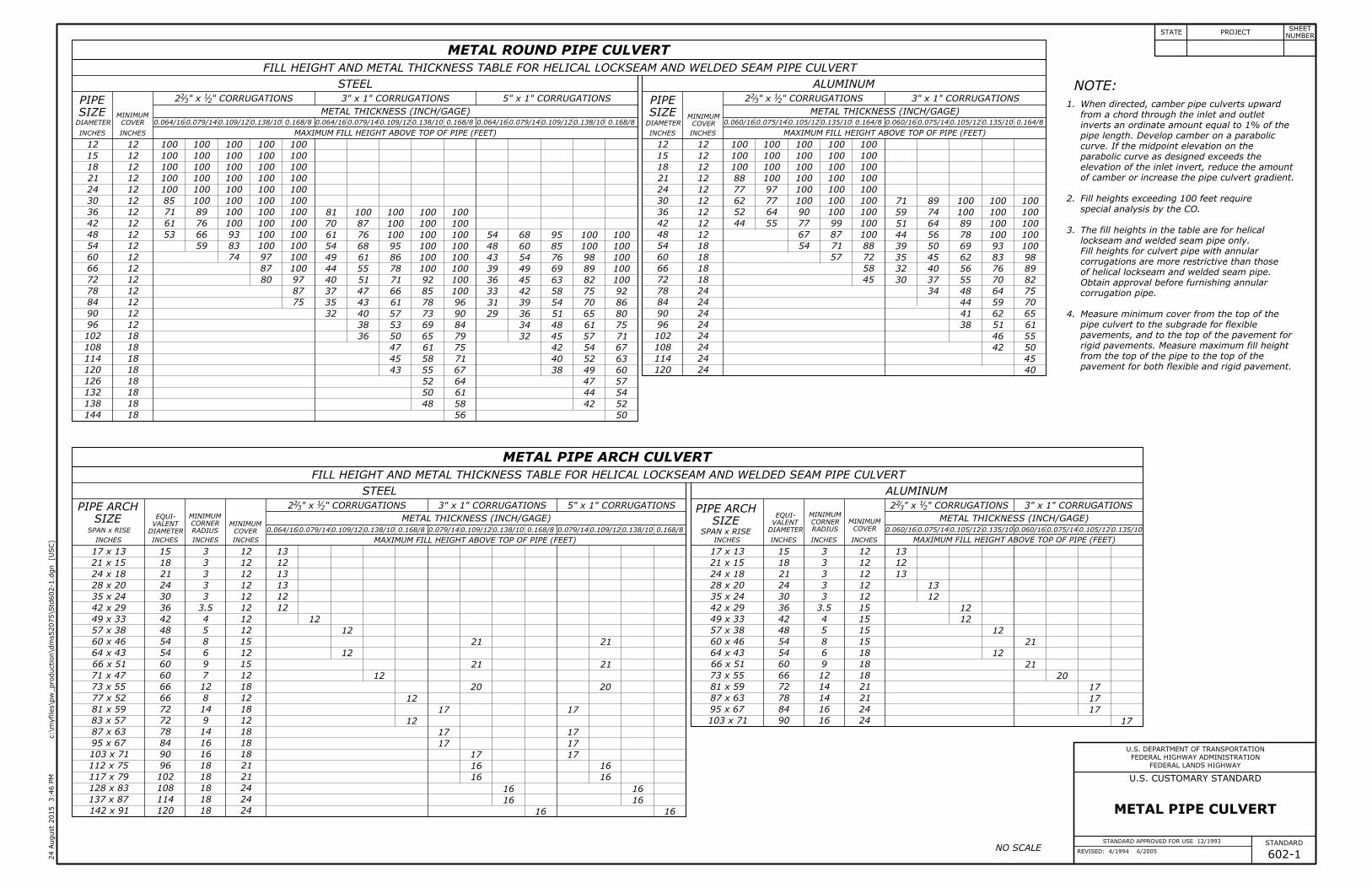
flexible and rigid pavement.
from the top of the pipe to the top of the pavement for both
pavement for rigid pavements. Measure maximum fill height
the subgrade for flexible pavements, and to the top of the
Measure minimum cover from the top of the pipe culvert to
camber or increase the pipe culvert gradient.
exceeds the elevation of the inlet invert, reduce the amount of
If the midpoint elevation on the parabolic curve as designed
to 1% of the pipe length. Develop camber on a parabolic curve.
through the inlet and outlet inverts an ordinate amount equal
When directed, camber pipe culverts upward from a chord
A
D
C
B
PIPE SIZE
602-5
STANDARD APPROVED FOR USE 12/1993
DRAFT: 2/2009
REVISED: 4/1994 6/2005
STATE PROJECTNUMBER
SHEET
U.S. DEPARTMENT OF TRANSPORTATION
FEDERAL HIGHWAY ADMINISTRATION
2:45 P
M
3 S
epte
mber 2
015
]U
SC
[
C:\
MyFiles\p
w_production\d
ms52075\Std
602-5.d
gn
FEDERAL LANDS HIGHWAY
U.S. CUSTOMARY STANDARD
STANDARD
PLASTIC PIPE CULVERT
12
12
12
12
12
12
12
48
42
36
30
24
18
12 57
52
38
38
38
27
27
36
30
24
18
15
12
12
12
12
12
12
12
10
10
10
10
10
10
48
42
36
30
24
18
12
12
12
12
12
12
21
21
25
22
22
18
26
27
31
28
28
24
INCHES
DIAMETER
INCHES MAXIMUM FILL HEIGHT (FEET)HEIGHT (FEET)
MAXIMUM FILL
INCHESINCHES
DIAMETER
MAXIMUM FILL HEIGHT (FEET)INCHESINCHES
DIAMETER 1.4771.2921.3851.1540.9230.8570.607
MINIMUM WALL THICKNESS (INCHES)
17
18
19
20
21
23
22
26
24
26
27
28
29
33
32
37
12
12
12
12
12
12
12
12
48
42
36
30
24
18
15
12
66
69
62
65
12
12
15
12
INCHES
DIAMETER
INCHES MAXIMUM FILL HEIGHT (FEET) INCHES
DIAMETER
INCHES MAXIMUM FILL HEIGHT (FEET)
MINIMUM WALL THICKNESS (INCHES)
0.358 0.438 0.358 0.438
6
6
6
6
6
6
66.5
63.5
65
55
45.5
33
43
36
37
29
24.5
14.5
88
88
64
54
46
42
36
30
24
18
15
12
INCHES
DIMENSIONS
INCHES
DIAMETER
NOTE:

NO SCALE
2.
1.
POLYVINYL CHLORIDE (PVC) PLASTIC ROUND PIPE CULVERT
SIZE
PIPE
FILL HEIGHT TABLE AND MINIMUM CELL CLASSIFICATION NUMBER PER ASTM D 1784
SMOOTH WALL (SOLID WALL) RIBBED
SIZE
PIPECOVER
MINIMUMNO. 12454
CELL CLASS.
NO. 12364
CELL CLASS.
COVER
MINIMUM
NO. 12454C
CELL CLASS.
NO. 12364C
CELL CLASS.
A B C D
END SECTION DIMENSIONS
PLASTIC PIPE END SECTION
SIDE
TOP
FRONT
FILL HEIGHT TABLE AND MINIMUM CELL CLASSIFICATION NUMBER PER ASTM D 3350
SMOOTH WALL (SOLID WALL) CORRUGATED RIBBED
SIZE
PIPE
SIZE
PIPE
SIZE
PIPENUMBER 335434C
CELL CLASSIFICATION
NO. 435400C
CELL CLASS.
NO. 335434C
CELL CLASS.COVER
MINIMUM
NO. 334433C
CELL CLASS.COVER
MINIMUM
COVER
MINIMUM
POLYETHYLENE (PE) PLASTIC ROUND PIPE CULVERT
flexible and rigid pavement.
from the top of the pipe to the top of the pavement for both
pavement for rigid pavements. Measure maximum fill height
the subgrade for flexible pavements, and to the top of the
Measure minimum cover from the top of the pipe culvert to
camber or increase the pipe culvert gradient.
exceeds the elevation of the inlet invert, reduce the amount of
If the midpoint elevation on the parabolic curve as designed
to 1% of the pipe length. Develop camber on a parabolic curve.
through the inlet and outlet inverts an ordinate amount equal
When directed, camber pipe culverts upward from a chord
A
D
C
B
PIPE SIZE
STANDARD APPROVED FOR USE 3/1996
DRAFT: 2/2009
REVISED: 6/2005 602-5M
STATE PROJECTNUMBER
SHEET
U.S. DEPARTMENT OF TRANSPORTATION
FEDERAL HIGHWAY ADMINISTRATION
]M
etric
[
C:\
MyFiles\p
w_production\d
ms52075\Std
602-5.d
gn
2:47 P
M
3 S
epte
mber 2
015
FEDERAL LANDS HIGHWAY
STANDARD
METRIC STANDARD
PLASTIC PIPE CULVERT
3.
DIAMETERMAXIMUM FILL HEIGHT (METERS) HEIGHT (METERS)
MAXIMUM FILL DIAMETER DIAMETER
MAXIMUM FILL HEIGHT (METERS)
MINIMUM WALL THICKNESS
15.4 21.7 23.4 29.3 35.1 32.8 37.5
8.0
8.0
9.5
8.5
8.5
7.5
6.5
6.5
7.5
6.5
6.5
5.5
300
300
300
300
300
300
1200
1050
900
750
600
450
3.0
3.0
3.0
3.0
3.0
3.0
300
300
300
300
300
300
900
750
600
450
375
300
8.0
8.0
11.5
11.5
11.5
16
17.5
300
300
300
300
300
300
300
1200
1050
900
750
600
450
300
Dimensions without units are millimeters.
MAXIMUM FILL HEIGHT (METERS)MAXIMUM FILL HEIGHT (METERS)DIAMETERDIAMETER
MINIMUM WALL THICKNESS
9.1 11.1 9.1 11.1
375
300
300
300 20 21
19 20
1200
1050
900
750
600
450
375
300
300
300
300
300
300
300
300
300
7.5
8.0
8.5
8.5
9.0
10.0
9.5
11.0
5.5
5.5
6.0
6.0
6.5
7.0
6.5
8.0
DIMENSIONS
DIAMETER
900
750
600
450
375
300
2235
2235
1625
1370
1170
1065
1090
915
940
735
620
370
1690
1615
1650
1395
1155
840
150
150
150
150
150
150
NOTE:

NO SCALE
dimension of all pipe arch culverts.
D equals the diameter of all round pipe or the rise 1.
TYPE II
TYPE I
SECTION B-B
SECTION A-A
Norm
al ditch lin
e
Subgrade s
hould
er
Pipe culvert
End of pip
e
FLOW
Flat bottom di
tch at culv
ert inlet
FLOW
Taper at 1
0:1 ratio
Taper at 10:1
ratio
FLOW
2D or
FLOW
Taper at 10
:1 ratio
2D or
Norm
al ditch lin
e
subgrade elevation
Maximum 2D or
Subgrade s
hould
er
or e
nd s
ection
End of pip
e b
evel
PIPE SIZE (D) WIDENING
DITCH WIDENING
Flat bottom ditc
h at culvert
inlet
A
A
B
B
section
End
PLAN PLAN
Original ground
in mountainous terrain
flat terrain. Taper at 5:1
Taper at 10:1 in rolling or 5:1 in mountainous terrain.
or flat terrain. Taper at
Taper at 10:1 in rolling
Normal ditch line
Pipe culvert
Original ground cut slope
Normal
(See table)
Ditch widening
Subgrade shoulder Normal ditch lineSubgrade shoulder
Pavement surface
Berm
Pavement surface
Subgrade
End section
Berm
pipe as staked
Slope at
ditch at end section
Flow line of
pipe as staked
Slope at
cut slope
Normal
Din lieu of 45° pipe elbow
30° pipe elbows may be required
At skewed pipe locations, 22.5° or
Standard 45° pipe elbow.
slope
1:3 max
ditch line
Normal
maximum slope
1:1.5
Cut Slope
slope
1:3 max
maximum slope
1:1.5
Cut Slope
D
ditch line
Normal
Subgrade
602-6
STANDARD APPROVED FOR USE 12/1993
REVISED: 4/1994 6/2005
TREATMENT IN CUT SLOPES
PIPE CULVERT INLET 30"
24"
18"
7'
6'
5'
STATE PROJECTNUMBER
SHEET
U.S. DEPARTMENT OF TRANSPORTATION
FEDERAL HIGHWAY ADMINISTRATION
8:11 A
M
3 D
ece
mber 2
015
]U
SC
[
c:\m
yfiles\p
w_production\d
ms52075\Std
602-6.d
gn
FEDERAL LANDS HIGHWAY
U.S. CUSTOMARY STANDARD
STANDARD
1'
1'
NOTE:
Berm
D
Berm
D
(min.)
4'
3" dip at center
(Min.)
4'

NO SCALE
dimension of all pipe arch culverts.
D equals the diameter of all round pipe or the rise 1.
TYPE II
TYPE I
SECTION B-B
SECTION A-A
Norm
al ditch lin
e
Subgrade s
hould
er
Pipe culvert
End of pip
e
FLOW
Flat bottom di
tch at culv
ert inlet
FLOW
Taper at 1
0:1 ratio
Taper at 10:1
ratio
FLOW
2D or
FLOW
Taper at 10
:1 ratio
2D or
Norm
al ditch lin
e
subgrade elevation
Maximum 2D or
Subgrade s
hould
er
or e
nd s
ection
End of pip
e b
evel
PIPE SIZE (D) WIDENING
DITCH WIDENING
Flat bottom ditc
h at culvert
inlet
A
A
B
B
section
End
PLAN PLAN
Original ground
in mountainous terrain
flat terrain. Taper at 5:1
Taper at 10:1 in rolling or 5:1 in mountainous terrain.
or flat terrain. Taper at
Taper at 10:1 in rolling
Normal ditch line
Pipe culvert
Original ground cut slope
Normal
(See table)
Ditch widening
Subgrade shoulder Normal ditch lineSubgrade shoulder
Pavement surface
Berm
Pavement surface
Subgrade
End section
Berm
pipe as staked
Slope at
ditch at end section
Flow line of
pipe as staked
Slope at
cut slope
Normal
Din lieu of 45° pipe elbow
30° pipe elbows may be required
At skewed pipe locations, 22.5° or
Standard 45° pipe elbow.
slope
1:3 max
ditch line
Normal
maximum slope
1:1.5
Cut Slope
slope
1:3 max
maximum slope
1:1.5
Cut Slope
D
ditch line
Normal
Subgrade
STANDARD APPROVED FOR USE 3/1996
REVISED: 6/2005 602-6M
TREATMENT IN CUT SLOPES
PIPE CULVERT INLET
Dimensions without units are millimeters.2.
750
600
450
2100
1800
1500
STATE PROJECTNUMBER
SHEET
U.S. DEPARTMENT OF TRANSPORTATION
FEDERAL HIGHWAY ADMINISTRATION
]M
etric
[
c:\m
yfiles\p
w_production\d
ms52075\Std
602-6.d
gn
8:29 A
M
3 D
ece
mber 2
015
FEDERAL LANDS HIGHWAY
STANDARD
METRIC STANDARD
300
75 dip at center
(Min.)
1200
NOTE:
Berm
D
Berm
D
(min.)
1200
300

NO SCALE
1.
2.
3.
4.
5.
6.
MULTIPLE ROUND PIPE INSTALLATION SUPPLEMENTAL CONCRETE PIPE TIE
PIPING PLUG
TRENCH INSTALLATIONEMBANKMENT INSTALLATION
CONCRETE ROUND PIPE CULVERT LEGEND:
Bedding material (uncompacted).
Embankment material placed in layers
Impermeable backfill material.
FILL HEIGHT AND PIPE CLASS TABLE
BEDDING DEPTH
PIPE
SIZE
MINIMUM SPACING
EMBANKMENT TRENCHDIAMETER
DEPTHPIPE SIZE (H)
CLASS VCLASS IVCLASS IIICLASS II
TRENCH
CLASS VCLASS IVCLASS IIICLASS II
EMBANKMENT
Construct a piping plug of impermeable backfill
material at the pipe inlet where granular
material is used for backfill. Width may be
adjusted to tie into impervious material.
Roadway embankment
Limits of pipe compactionSECTION A-A
When directed, camber pipe culverts upwards from
a chord through the inlet and outlet inverts an
ordinate amount equal to 1% of the pipe length.
Develop camber on a parabolic curve. If the midpoint
elevation on the parabolic curve as designed exceeds
the elevation of the inlet invert, reduce the amount
of camber or increase the pipe culvert gradient.
Measure minimum cover from the top of the pipe
culvert to the subgrade for flexible pavements, and
to the top of the pavement for rigid pavements.
Measure maximum fill height from the top of the
pipe to the top of the pavement for both flexible
and rigid pavements.
Pipe compaction limits shown are for pipe installation
in an embankment. For pipe installation in a trench,
the compaction limits shall be the walls of the trench.
Where unyielding or unstable material is encountered,
install the pipe culvert according to the limits of pipe
Maximum fill heights for pipe culvert installations
may be increased on approval of site-specific
structural pipe designs meeting the criteria of
AASHTO Standard Specifications for Highway Bridges.
Use Supplemental Concrete Pipe Tie when specified
in the contract documents.
A
A
Compacted backfill material placed in layers
lean concrete backfill in accordance with Section 614
Bedding (See table)Bedding (See table)
H
Width
60° 60°
H
H
H
H
(See table)
Minimum spacing
H
Finished subgrade before trench excavation
embankment height
Finished subgrade or
to springline
backfill
Compacted
Piping plug
end treatment
Culvert
Embankment slope
High water elevation
Pipe culvert
holes (typ.)
Concrete pipe tie
when precast
Tapered holes permitted
over pipe joint
Do not install fastener
O Ring if required
2H2H
602-7
STANDARD APPROVED FOR USE 12/1993
DRAFT: 6/2008
REVISED: 4/1994 6/2005
CULVERT INSTALLATION
CONCRETE PIPE
compaction shown on Standard 602-3.
INCHES
DIAMETER
INCHES
COVER
MINIMUM
14
12
12
12
12
12
12
12
12
12
12
108
96
84
72
60
48
36
30
24
18
12
15
13
13
13
15
12
9
9
10
10
10
20
20
19
17
17
13
9
13
10
10
10
30
30
28
26
20
15
15
25
15
MAXIMUM FILL HEIGHT ABOVE TOP OF PIPE IN FEET
41
44
44
41
35
30
39
23
18
15
15
15
15
15
10
13
15
13
18
26
24
23
20
20
16
13
16
15
13
18
37
35
32
30
26
20
22
31
26
49
49
49
56
46
40
45
13
> 54"
12" TO 54"
6"
4"
OVER 96"
36"-96"
12"-36"
48"
0.5H
15"
72"
72"
2H
" min.212'-6
not exceeding 6" compacted depth.
not exceeding 6" compacted depth, or
12"
1'-0" (min.)
" dia. hole for411
" max.212'-9
typical
2" m
ax.
1'-0"±
1'-3" min.
1'-5" max.
1" dia. Joint tie
STATE PROJECTNUMBER
SHEET
U.S. DEPARTMENT OF TRANSPORTATION
FEDERAL HIGHWAY ADMINISTRATION
12:10 P
M
3 D
ece
mber 2
015
]U
SC
[
c:\m
yfiles\p
w_production\d
ms52075\Std
602-7.d
gn
FEDERAL LANDS HIGHWAY
U.S. CUSTOMARY STANDARD
STANDARD
NOTE:
H H
H H

NO SCALE
1.
2.
3.
4.
5.
6.
MULTIPLE ROUND PIPE INSTALLATION SUPPLEMENTAL CONCRETE PIPE TIE
PIPING PLUG
TRENCH INSTALLATIONEMBANKMENT INSTALLATION
CONCRETE ROUND PIPE CULVERT LEGEND:
Bedding material (uncompacted).
Embankment material placed in layers
Impermeable backfill material.
FILL HEIGHT AND PIPE CLASS TABLE
BEDDING DEPTH
PIPE
SIZE
MINIMUM SPACING
EMBANKMENT TRENCHDIAMETER
DEPTHPIPE SIZE (H)
CLASS VCLASS IVCLASS IIICLASS II
TRENCH
CLASS VCLASS IVCLASS IIICLASS II
EMBANKMENT
Construct a piping plug of impermeable backfill
material at the pipe inlet where granular
material is used for backfill. Width may be
adjusted to tie into impervious material.
Roadway embankment
Limits of pipe compactionSECTION A-A
When directed, camber pipe culverts upwards from
a chord through the inlet and outlet inverts an
ordinate amount equal to 1% of the pipe length.
Develop camber on a parabolic curve. If the midpoint
elevation on the parabolic curve as designed exceeds
the elevation of the inlet invert, reduce the amount
of camber or increase the pipe culvert gradient.
Measure minimum cover from the top of the pipe
culvert to the subgrade for flexible pavements, and
to the top of the pavement for rigid pavements.
Measure maximum fill height from the top of the
pipe to the top of the pavement for both flexible
and rigid pavements.
Pipe compaction limits shown are for pipe installation
in an embankment. For pipe installation in a trench,
the compaction limits shall be the walls of the trench.
Where unyielding or unstable material is encountered,
install the pipe culvert according to the limits of pipe
Maximum fill heights for pipe culvert installations
may be increased on approval of site-specific
structural pipe designs meeting the criteria of
AASHTO Standard Specifications for Highway Bridges.
Use Supplemental Concrete Pipe Tie when specified
in the contract documents.
A
A
Compacted backfill material placed in layers
lean concrete backfill in accordance with Section 614
Bedding (See table)Bedding (See table)
H
Width
60° 60°
H
H
H
H
(See table)
Minimum spacing
H
Finished subgrade before trench excavation
embankment height
Finished subgrade or
to springline
backfill
Compacted
Piping plug
end treatment
Culvert
Embankment slope
High water elevation
Pipe culvert
holes (typ.)
Concrete pipe tie
when precast
Tapered holes permitted
over pipe joint
Do not install fastener
O Ring if required
2H2H
STANDARD APPROVED FOR USE 3/1996
DRAFT: 6/2008
REVISED: 6/2005 602-7M
CULVERT INSTALLATION
CONCRETE PIPE
7. Dimensions without units are millimeters.
compaction shown on Standard M602-3.
not exceeding 150 compacted depth.
not exceeding 150 compacted depth, or
15.0
15.0
15.0
17.0
14.0
12.0
13.5
4.0
11.0
10.5
9.5
9.0
8.0
6.0
6.5
9.0
8.0
MAXIMUM FILL HEIGHT ABOVE TOP OF PIPE IN METERS
8.0
7.0
7.0
6.0
6.0
5.0
4.0
5.0
4.5
4.0
5.5
5.5
4.5
4.5
4.5
4.5
4.5
3.0
4.0
4.5
4.0
5.5
12.5
13.5
13.5
12.5
10.5
9.0
12.0
7.0
9.0
9.0
8.5
8.0
6.0
4.5
4.5
7.5
4.5
DIAMETER COVER
MINIMUM
350
300
300
300
300
300
300
300
300
300
300
4.5
4.0
4.0
4.0
4.5
3.5
2.5
2.5
3.0
3.0
3.0
6.0
6.0
5.5
5.0
5.0
4.0
2.5
4.0
3.0
3.0
3.0
2700
2400
2100
1800
1500
1200
900
750
600
450
300
> 1350
300 TO 1350
150
100
300
300 (min.)
OVER 2400
900 - 2400
300 - 900
1220
0.5H
380
1830
1830
2H
25 dia. Joint tie
30 dia. hole for
375 min.
425 max.
750 min.
850 max.
typical
50 m
ax.
300 ±
STATE PROJECTNUMBER
SHEET
U.S. DEPARTMENT OF TRANSPORTATION
FEDERAL HIGHWAY ADMINISTRATION
]M
etric
[
c:\m
yfiles\p
w_production\d
ms52075\Std
602-7.d
gn
12:11 P
M
3 D
ece
mber 2
015
FEDERAL LANDS HIGHWAY
STANDARD
METRIC STANDARD
NOTE:
H H
H H

A
Variations in design and dimensions are permitted to
allow for manufacturer's standards.
Fabricate the outlet end section with a groove end and
the inlet end section with a tongue end.
Warp embankment slopes to match the slope of the
flared end section.
1.
2.
3.
PLAN PLAN
ELEVATIONELEVATION
SECTION A-A SECTION B-B
END SECTIONS FOR ROUND PIPE CULVERT
PIPE
SIZE
T A B C L W F R1 R2 R3
1
3
1
3
NO SCALE
A
A B
B
CL CL
CLCL
--
--
--
NOTE:
BC
L
BC
L
602-8
STANDARD APPROVED FOR USE 12/1993
REVISED: 4/1994 6/2005
INCHES
DIMENSIONS
INCHES
DIAMETER
48
42
36
33
30
27
24
21
18
15
12 2
24
21
15
12
9
9
6
4
412
212
432
3
413
213
433
4
214
5
2110
219
"2113
72
63
63
54
48
36
27
27
24 8748
2143
2159
2125
4319
2137
8772
96
96
96
96
73
73
73
84
78
72
66
60
54
48
42
36
30
24
2173
2173
4373
49
43
37
34
31
28
25
22
19
16
13 8110
22
22
20
15
14
13
12
11
9
12
11
11
9
8
9
8
5
6
4
217
2112
2115
2116
4316
2118
4323
4123
2114
2117
FOR ROUND PIPE
CONCRETE END SECTION
STATE PROJECTNUMBER
SHEET
U.S. DEPARTMENT OF TRANSPORTATION
FEDERAL HIGHWAY ADMINISTRATION
11:51 A
M
7 D
ece
mber 2
015
]U
SC
[
c:\m
yfiles\p
w_production\d
ms52075\Std
602-8.d
gn
FEDERAL LANDS HIGHWAY
U.S. CUSTOMARY STANDARD
STANDARD
T+
1"
T+
1"
TDia
meter
T
F
A
R
1
R2
TWT
TDia.T
R3
TDia.T
TWT
TWT TWT
TDia
meter
T

A
Variations in design and dimensions are permitted to
allow for manufacturer's standards.
Fabricate the outlet end section with a groove end and
the inlet end section with a tongue end.
Warp embankment slopes to match the slope of the
flared end section.
1.
2.
3.
PLAN PLAN
ELEVATIONELEVATION
SECTION A-A SECTION B-B
END SECTIONS FOR ROUND PIPE CULVERT
PIPE
SIZE
T A B C L W F R1 R2 R3
1
3
1
3
NO SCALE
A
A B
B
CL CL
CLCL
--
--
--
NOTE:
BC
L
BC
L
STANDARD APPROVED FOR USE 3/1996
REVISED: 6/2005 602-8M
FOR ROUND PIPE
CONCRETE END SECTION
Dimensions without units are millimeters.4.
DIAMETER
1200
1050
900
825
750
675
600
525
450
375
300
125
113
100
94
88
82
75
69
63
57
50
600
525
375
345
300
263
238
225
225
150
100
1800
1585
1585
1485
1350
1200
1088
900
675
675
600
DIMENSIONS
600
825
825
938
494
638
750
925
1150
1150
1222
2400
2400
2400
2400
1844
1838
1838
1825
1825
1825
1822
2100
1950
1800
1650
1500
1350
1200
1050
900
750
600
1225
1095
925
865
775
700
625
550
475
400
325
420
412
388
312
253
550
550
500
438
375
362
350
325
300
275
225
300
275
275
225
200
225
200
125
188
150
100
580
594
462
STATE PROJECTNUMBER
SHEET
U.S. DEPARTMENT OF TRANSPORTATION
FEDERAL HIGHWAY ADMINISTRATION
]M
etric
[
c:\m
yfiles\p
w_production\d
ms52075\Std
602-8.d
gn
11:51 A
M
7 D
ece
mber 2
015
FEDERAL LANDS HIGHWAY
STANDARD
METRIC STANDARD
T+
25T+
25
TDia
meter
T
F
A
R
1
R2
TWT
TDia.T
R3
TDia.T
TWT
TWT TWT
TDia
meter
T

METAL END SECTIONS FOR ROUND PIPE CULVERT
METAL END SECTIONS FOR PIPE ARCH CULVERT
A H WOVERALL
WIDTH Slope=4 Slope=6
L
Slope=6Slope=4
LOVERALL
WIDTHWHARISESPAN
EQUIV.
Ø
NO SCALE602-9
STANDARD APPROVED FOR USE 6/2005
DRAFT: 1/2016
REVISED:
sections when the span is greater than 30".
30" and smaller cross drainage end sections.
Safety bars are not required on 18" and smaller
INCHES
Ø
SIZE
PIPE
INCH/GAGE
(MIN.)
THICK
METAL DIMENSIONS IN INCHES
295
260
224
189
154
118
83
47
197
173
150
126
102
79
55
32
98
92
86
80
66
60
46
40
66
60
54
48
42
36
30
24
12
12
12
12
9
9
6
6
16
16
16
16
12
12
8
8
0.109/12
0.109/12
0.109/12
0.109/12
0.109/12
0.109/12
0.064/16
0.064/16
60
54
48
42
36
30
24
18
PIPE SIZE (INCHES)
72
60
54
48
42
36
30
24
18
82
70
63
56
48
41
35
28
21
56
46
42
37
32
29
24
20
15
INCH/GAGE
(MIN.)
THICK
METAL
0.109/12
0.109/12
0.109/12
0.109/12
0.109/12
0.109/12
0.109/12
0.064/16
0.064/16
16
16
16
16
16
12
12
8
8
12
12
12
12
12
9
9
6
6
88
76
69
62
54
47
40
33
27
120
107
101
94
86
71
64
49
43
185
146
130
110
90
75
55
40
20
278
218
195
165
136
112
83
60
30
WITH SAFETY BARS
METAL END SECTIONS
STATE PROJECTNUMBER
SHEET
U.S. DEPARTMENT OF TRANSPORTATION
FEDERAL HIGHWAY ADMINISTRATION
12:52 P
M
8 D
ece
mber 2
015
]U
SC
[
c:\m
yfiles\p
w_production\d
ms52075\Std
602-9.d
gn
FEDERAL LANDS HIGHWAY
U.S. CUSTOMARY STANDARD
STANDARD
Use end sections on 1V:4H to 1V:6H slopes only.
Use toe plate extension where shown on the plans.
Fabricate safety and longitudinal bars from steel pipe
conforming to ASTM A53 schedule 40 specifications.
Galvanize bars hot dipped after fabrication.
A longitudinal bar is required for cross drainage end
1.
2.
3.
4.
5.
6.
SAFETY BAR DETAILSCROSS DRAINAGE END SECTION
PARALLEL DRAINAGE
END SECTION
PIPE ARCH CULVERT CONNECTOR DETAILS
PARALLEL DRAINAGE END SECTIONCROSS DRAINAGE END SECTIONROUND PIPE CULVERT
FRONT VIEW ELEVATION ELEVATION
FRONT VIEW
SECTION A-A
SECTION B-B
LONGITUDINAL DRAINAGE BAR PARALLEL BARS
TYPE #3
Alternate view
for female end
B
B
Slope
1
spacing 1
Slope
A
FOR ALL SIZES OF CONCRETE
ROUND OR PIPE ARCHES
A
A
ANOTE:
Use additional longitudinal bars if spacing exceeds
Safety and longitudinal bars are not required on
parallel drainage end sections.
spacing
FOR METAL ROUND PIPESAND LARGER. FOR PIPE ARCHES
flatten end, then bend outside
to fit pipe
Corrugation sized
safety bars
Parallel
Longitudinal bar
to safety bar (typ.)
Weld longitudinal bar
Longitudinal bars
D
Varies
Rise
Overall width
D
Overall width
AWA
L L
or Rise (
R)
Dia
meter (
D)
Top of end section
Top of end section
(typ.)
Safety barsSafety bars (typ.)
Mastic where required
HH
H
H
tightly together
the surfaces
Bolt to hold
as end section)
(same thickness
plate extension
Optional toe
as end section)
(same thickness
plate extension
Optional toe
Side lug
head bolts (typ.)
galvanized
Type 2 threaded rod
with Type 1 strap or
corrugations and attach
lugs to be bolted to end section
over top of end section. Side
bolt w/nut
galvanized
reinforcing bar
galvanized
galvanized steel
AWA
or Rise (
R)
Dia
meter (
D)
TYPE #1 TYPE #2
head bolts (typ.)
galvanized
strap
Galvanized
tightly together
the surface
Bolt to hold
length of end section
Reinforced edge full
(See Section A-A)
rolled snugly against steel rod
Edge of sidewall sheet
Pipe
4"
2"
8"
6"
2"
6"
8"
(max.)48"
4"
4"
" x 6"21 " galvanized threaded rod 2
1
2"
8"
15" THRU 24"
FOR METAL ROUND PIPES 30"
21" X 15" AND LARGER
" (min.) dia.21
rod or #4
"21" x 4
3Form 2
sm
ooth sle
eve
24"
8"
2"
6"
6"
(max.)24"
4"
" carriage21
48" (max.)
" slots851" x
"835
4" to match end section sides.
"213
1"
" carriage21
"83D -
30" on larger end sections.
0.079", all others are 0.109".
18" diameter sleeves have a thickness of
DIMENSIONS (INCHES)
4"
" (approx.)
81
3" galvanized steel pipe:
(See Section A-A)
length of end section
Reinforced edge full

METAL END SECTIONS FOR ROUND PIPE CULVERT
METAL END SECTIONS FOR PIPE ARCH CULVERT
A H WOVERALL
WIDTH Slope=4 Slope=6
L
Slope=6Slope=4
LOVERALL
WIDTHWHARISESPAN
EQUIV.
Ø
NO SCALESTANDARD APPROVED FOR USE 3/1996
DRAFT: 1/2016
REVISED: 5/1997 6/2005 602-9M
WITH SAFETY BARS
METAL END SECTIONS
Ø
SIZE
PIPE
(MIN.)
THICK
METAL DIMENSIONS
1500
1350
1200
1050
900
750
600
450
2.77
2.77
2.77
2.77
2.77
2.77
1.63
1.63
400
400
400
400
300
300
200
200
300
300
300
300
225
225
150
150
1650
1500
1350
1200
1050
900
750
600
2450
2300
2150
2000
1650
1500
1150
1000
5000
4400
3800
3200
2600
2000
1400
800
7500
6600
5700
4800
3900
3000
2100
1200
DIMENSIONS
(MIN.)
THICK
METALPIPE SIZE
1800
1500
1350
1200
1050
900
750
600
450
2075
1775
1600
1425
1225
1050
875
700
525
1425
1175
1075
950
825
725
600
500
375
2.77
2.77
2.77
2.77
2.77
2.77
2.77
1.63
1.63
400
400
400
400
400
300
300
200
200
300
300
300
300
300
225
225
150
150
2225
1925
1750
1575
1375
1200
1025
850
675
3025
2725
2550
2375
2175
1800
1625
1250
1075
4700
3700
3300
2800
2300
1900
1400
1000
500
7050
5550
4950
4200
3450
2850
2100
1500
750
STATE PROJECTNUMBER
SHEET
U.S. DEPARTMENT OF TRANSPORTATION
FEDERAL HIGHWAY ADMINISTRATION
]M
etric
[
c:\m
yfiles\p
w_production\d
ms52075\Std
602-9.d
gn
1:06 P
M
8 D
ece
mber 2
015
FEDERAL LANDS HIGHWAY
STANDARD
METRIC STANDARD
Use end sections on 1V:4H to 1V:6H slopes only.
Use toe plate extension where shown on the plans.
Fabricate safety and longitudinal bars from steel pipe
conforming to ASTM A53 schedule 40 specifications.
Galvanize bars hot dipped after fabrication.
A longitudinal bar is required for cross drainage end
1.
2.
3.
4.
5.
6.
SAFETY BAR DETAILSCROSS DRAINAGE END SECTION
PARALLEL DRAINAGE
END SECTION
PIPE ARCH CULVERT CONNECTOR DETAILS
PARALLEL DRAINAGE END SECTIONCROSS DRAINAGE END SECTIONROUND PIPE CULVERT
FRONT VIEW ELEVATION ELEVATION
FRONT VIEW
SECTION A-A
SECTION B-B
LONGITUDINAL DRAINAGE BAR PARALLEL BARS
TYPE #3
Alternate view
for female end
B
B
Slope
1
spacing 1
Slope
A
FOR ALL SIZES OF CONCRETE
ROUND OR PIPE ARCHES
A
A
ANOTE:
Use additional longitudinal bars if spacing exceeds
Safety and longitudinal bars are not required on
parallel drainage end sections.
spacing
FOR METAL ROUND PIPESAND LARGER. FOR PIPE ARCHES
flatten end, then bend outside
to fit pipe
Corrugation sized
safety bars
Parallel
Longitudinal bar
to safety bar (typ.)
Weld longitudinal bar
Longitudinal bars
D
Varies
Rise
Overall width
D
Overall width
AWA
L L
or Rise (
R)
Dia
meter (
D)
Top of end section
Top of end section
(typ.)
Safety barsSafety bars (typ.)
Mastic where required
HH
H
H
tightly together
the surfaces
Bolt to hold
as end section)
(same thickness
plate extension
Optional toe
as end section)
(same thickness
plate extension
Optional toe
Side lug
head bolts (typ.)
galvanized
Type 2 threaded rod
with Type 1 strap or
corrugations and attach
lugs to be bolted to end section
over top of end section. Side
bolt w/nut
galvanized
reinforcing bar
galvanized
galvanized steel
AWA
or Rise (
R)
Dia
meter (
D)
TYPE #1 TYPE #2
head bolts (typ.)
galvanized
strap
Galvanized
tightly together
the surface
Bolt to hold
length of end section
Reinforced edge full
(See Section A-A)
rolled snugly against steel rod
Edge of sidewall sheet
Pipe
750 mm on larger end sections.
750 mm and smaller cross drainage end sections.
Safety bars are not required on 450 mm and smaller
Dimensions without units are millimeters.
2.01 mm, all others are 2.77 mm.
450 mm diameter sleeves have a thickness of
7.
(max.)600
50
200
150
sm
ooth sle
eve
600
D - 10
FOR METAL ROUND PIPES 750
525 X 375 AND LARGER375 THRU 600
M12 galvanized threaded rod M12 x 150
2005
0
150
150
(max.)120
0
100
50
200
100
50
200
1200 (max.)
25
90
25 x 15 slots
100
133 76.2 galvanized steel pipe:
100 to match end section sides.
11.11 dia. min.
rod or #13
M12 carriage
Form 68 x 13
sections when the span is greater than 750 mm.
150
100
100
M12 carriage
3 (approx.)
(See Section A-A)
length of end section
Reinforced edge full