Metal Framing, Channel, Fittings, Pipe Straps and Beam … material is zinc coated after fab ri ca...
89
Metal Framing, Channel, Fittings, Pipe Straps and Beam Clamps 2008 Edition
Transcript of Metal Framing, Channel, Fittings, Pipe Straps and Beam … material is zinc coated after fab ri ca...

Metal Framing,Channel, Fittings,Pipe Straps andBeam Clamps
2008 Edition
SSTRUT-E4.pdf 1 1/31/2012 10:30:07 AM

ISO9001 : 2000
• ISO 9001 : 2000 REGISTERED MANUFACTURER •
Thomas & Betts is dedicated to improving its already high quality standards. To date, we have achieved ISO 9001 : 2000 certification for more than 50 plants and distribution centers worldwide and continue to commitresources to the ISO certification program.
WARRANTYThomas & Betts manufactures its goods and tools in a manner to be free from defects. Should any defectoccur in its goods (within two years) or tools (within ninety days), Thomas & Betts, upon prompt notification,will at its option, exchange or repair the goods or tools or refund the purchase price.
LIMITATIONS AND EXCLUSIONSTHIS WARRANTY IS IN LIEU OF ALL OTHER REPRESENTATIONS, CONDITIONS AND WARRANTIES, EXPRESSED ORIMPLIED, STATUTORY OR OTHERWISE (INCLUDING STATUTORY IMPLIED CONDITIONS AND WARRANTIES OF MERCHANTABILITY AND FITNESS FOR A PARTICULAR PURPOSE) AND UNDER NO CIRCUMSTANCES SHALL THOMAS & BETTS BE LIABLE FOR ANY INCIDENTAL OR CONSEQUENTIAL DAMAGES OR LOSSES, INCLUDING, WITHOUT LIMITATION, PERSONAL INJURY CAUSED BY IMPROPER USE OR APPLICATION OF ANY THOMAS & BETTS PRODUCT.
SSTRUT-E4.pdf 2 1/31/2012 10:30:07 AM

3
TABLE OF CONTENTS
FINISHES AND MATERIALS.............................................................................................................................................................5
SECTION 1 - CHANNELS AND CONCRETE INSERTS .................................................................................................................7Channels ............................................................................................................................................................................................8Welded Combinations ......................................................................................................................................................................10End Caps and Closure Strips ..........................................................................................................................................................10Concrete Inserts................................................................................................................................................................................11
SECTION 2 - THREADED PRODUCTS AND HARDWARE ........................................................................................................13Threaded Rod and Accessories ......................................................................................................................................................14
SECTION 3 - FITTINGS AND BRACKETS ..................................................................................................................................19Flat Fittings........................................................................................................................................................................................2090° Fittings ........................................................................................................................................................................................21Angular Fittings ................................................................................................................................................................................23“Z” Shape Fittings ............................................................................................................................................................................23“U” Shape Fittings ............................................................................................................................................................................24Wing Fittings ....................................................................................................................................................................................25Brackets ............................................................................................................................................................................................26Post Bases ........................................................................................................................................................................................28Special Application Fittings and Brackets ......................................................................................................................................29
SECTION 4 - BEAM CLAMPS ......................................................................................................................................................31Beam Clamps for Mounting Channel ..............................................................................................................................................32Beam Clamps for Hanging Rod ......................................................................................................................................................34Beam Clamps for Mounting Pipe and Conduit................................................................................................................................37Beam Fittings ....................................................................................................................................................................................38 SECTION 5 - PIPE STRAPS, PIPE CLAMPS AND HANGERS ....................................................................................................41Conduit and Cable Clamps ..............................................................................................................................................................42Pipe Hangers ....................................................................................................................................................................................51Seismic Bracing ................................................................................................................................................................................54Hanger Accessories..........................................................................................................................................................................55 SECTION 6 - SURFACE RACEWAY AND LIGHTING SYSTEMS ..............................................................................................57Fixture Fittings ..................................................................................................................................................................................58Kindorf® Channel Boxes and Receptacles ......................................................................................................................................60Kindorf® Fixture Accessories ............................................................................................................................................................61Electrical Applications ......................................................................................................................................................................61
SECTION 7 - RIGHT ANGLE SLOTTED METAL FRAMING ........................................................................................................65 SECTION 8 - ENGINEERING DATA AND SPECIFICATIONS ......................................................................................................69 ALPHANUMERIC INDEX ................................................................................................................................................................86
SSTRUT-E4.pdf 3 1/31/2012 10:30:07 AM

4
SSTRUT-E4.pdf 4 1/31/2012 10:30:07 AM

5
Finishes and Materials
SPECIAL MATERIALSAluminum (Suffix ALC)
Superstrut® channel is available in aluminum.Fittings in HDG finish or fiberglass materialare suggested for fastening products.
Stainless Steel
Superstrut® channel is supplied in Type304 (SS) and Type 316 (T316L) stainlesssteel. All fittings and accessories are in316SS (SS6). Contact your RegionalSales Office for availability.
Thomas & Betts reserves the right tochange ma te ri al and finish spec i fi ca tionswithout notice, to improve its prod ucts.
Hot-Dipped Galvanized (Suffix HDGC)The material is zinc coated afterfab ri ca tion providing total product pro tec tion on all surfaces. The fab ri cat edchan nel or fitting is sus pend ed and thendipped into tanks of hot zinc for a prolonged period, creating a co her entbond. The result is superior cor ro sionresistance as compared to pregalvanizedmaterial. Hot-dipped galvanizing is notrec om mend ed for thread ed pro ducts,considering the zinc coating thick nesswill often disrupt the threads. Superstrut®
hot-dipped galvanized is in conformancewith ASTM Spec i fi ca tions A-123 (for mer lyA-386) and A-153. Superstrut chan nelsmaintain a min i mum 1.5 oz. of zinc persquare foot of steel or 2.5 mils (ASTM A-123, Thick ness Grade 65). Thisfinish is also referred to as “Hot-dippedgalvanized af ter fabrication.”
Epoxy Powder Coated — Green, Grayor White (Suffix GR, GY or WH)
Epoxy powder resins are applied elec tro stat i cal ly to the steel after fab ri ca tion. Once the material is com plete ly covered with the powder-formepoxy, it proceeds through a 400°F(204°C) ba king process for ten minutes,cre at ing a chemical bond. This re sults ina minimum of 1.5 mil thick ness of epoxycoating pro vid ing excellent re sis tance tochipping or peeling.
FINISHES ON STEEL
Bare (Suffix BC)
Pregalvanized (Suffix PGC)
A zinc coating is applied by hot-dip pingthe steel coil at the mill prior to fabrication. Once the ma te ri al is worked byroll-form ing, cutting, or punching, minimalpro tec tion is pro vid ed for raw edges. Thisweak ness is typical with precoated ma te ri al and af fects the channel sectionaround holes, extreme ends, and theedges of the U-shape lips. Superstrut®
pre galvanized material is in con form ancewith ASTMA-525/G-90 spec i fi ca tion standards,re pre sent ing 0.90 oz. of zincper square foot of steel. This finish isoften referred to as “hot-dipped mill gal va nized” or “mill galvanized.”
Electrogalvanized (Suffix EGC)
Often referred to as “zinc plated” or “elec tro plat ed zinc,” the steel and 0.5 mils of zinc are bonded by an elec tro ly sis process. Electrogalvanizing ismost com mon ly applied to small fittings, hardware, and thread ed products.
GoldGalv® (No Suffix)
Gold colored zinc dichromate is appliedover the zinc, pro duc ing a chemicallybonded non porous barrier for pro tec tionfrom mois ture and air. This ex tends theprotective life of the zinc, and pro videsan excellent base for paint, if desired.The GoldGalv® hardware finish alsoprovides a low elec tri cal resistance whengrounding of the system is required.Superstrut® channel and fittings are platedafter fabrication, so there are noun pro tect ed edges from cutting orpunch ing. Where field cutting is necessaryor scratches occur due to con struc tionhandling, you still have the sacrificialprotection of the plated zinc to minimizethe corrosion of raw edges and pre ventspreading.
For full line of non metallic channel and accessories, please see our new non metallic Cable Tray and Strut Systems Catalogue NMCT-E.
5-e.pdf 1 4/3/2012 4:15:02 PM

66
SSTRUT-E4.pdf 6 1/31/2012 10:30:07 AM

7
Channels and Concrete Inserts SECTION 1
CHANNEL
Material
Steel channels are cold-roll formed from strip steel.Aluminum and Fiberglass channels are extruded profiles.
Material Thickness
All series 1200 12 gauge materialAll series 1400 14 gauge materialAll series 1600 16 gauge ribbed material
Standard Lengths
Standard lengths for channel are 10 ft and 20 ft with a tolerance of +1/8". Special lengths can be requested; however, minimum quantities may apply. Channels aresold per foot.
Warning
Load tables, charts, and de sign criteria provided in thiscatalogue are intended as guides only. Se lec tion of pro per product, support spacing, erec tion, and place mentare the responsibility of the user.
When im prop er ly used as tools of erection pipe hangerproducts have oc ca sio nal ly failed. To avoid an accident,the user is cau tioned to use the product only as it wasintended.
CONCRETE INSERT
Material
Superstrut continuous insert channel is manufacturedfrom 12 gauge hot rolled strip steel in two basic sizes as follows:
Cat. No. A3021-5/8" x 1-5/8" 7/8" slot
Cat. No. C3021-5/8" x 1-3/8" 7/8" slot
Cat. No. C3021-5/8" x 1-3/8" 7/8" slot
Standard Lengths
Standard lengths are 10 ft and 20 ft. Product is sup pliedwith foam filler and end caps to prevent concrete fromseeping into channel.
Application
For casting into concrete walls, floors or ceilings to pro vide for attachment anywhere along the continuousslot.
Design Data
Load ratings as shown have a safety factor of 3 in 3000lb. hard rock concrete. Where sound concrete does notexist, the load ratings shall not apply.
GoldGalv® hardware finish is standard for all SuperstrutConcrete insert prod ucts. This is a multi-process finish ofelectro-plated zinc, followed by gold colored zinc dichro mate to give ex cel lent corrosion resistance and asuperior paint base.
For more information on load design, see Section 8 for Engineering Data and Specifications.
For full line of non metallic channel and accessories, please see our new non metallic Cable Tray and Strut Systems Catalogue NMCT-E.
SSTRUT-E4.pdf 7 1/31/2012 10:30:07 AM

SECTION 1 Channels and Concrete Inserts
A12
00 1
2 ga
uge
A14
00 1
4 ga
uge
D12
00 1
2 ga
uge
Cha
nnel
s at
Ful
l Sca
le
Ava
ilab
le in
10
and
20
foot
leng
ths
15 /
8"7 /
8"
15 /
8"
15 /
8"
1"
7 /8"
13/ 1
6"
7/8"
15 /
8"
15 /
8"
7 /8"
27 /
16"
15 /
8"7 /
8"
31 /
4"
15 /
8"
15 /
8"7 /
8"
15 /
8"
15 /
8"
7 /8"
7 /8"
13/ 1
6"
13 /
8"
AR
S
E R
IES
A
SE
RIE
SB
S
E R
IES
BR
S
E R
IES
CS
E R
IES
D
SE
RIE
S
E
SE
RIE
S
H
SE
RIE
S
16 g
auge
onl
y16
gau
ge o
nly
B12
00 1
2 ga
uge
B14
00 1
4 ga
uge
H12
00 1
2 ga
uge
E12
00 1
2 ga
uge
C12
00 1
2 ga
uge
8
SSTRUT-E4.pdf 8 1/31/2012 10:30:07 AM

9
Channels and Concrete Inserts SECTION 1
Ho
le C
onf
igur
atio
n
Cha
nnel
with
Kno
ckou
tsH
alf
Slo
t C
hann
elS
lott
ed C
hann
elS
W “
Slo
tted
Wid
e” C
hann
elP
unch
ed C
hann
el
Slo
ts:
9/16
” X
1-1
/8”
Slo
ts:
7/16
” X
3”
Slo
ts:
9/16
” X
3”
Hol
es:
9/16
”K
O:
1/2”
HO
LE C
ON
FIG
UR
AT
ION
FIN
ISH
ON
ST
EE
LS
PE
CIA
L M
AT
ER
IALS
Suf
fixS
uffix
Suf
fix
bla
nkP
lain
, no
hol
esB
CB
are
AL
Alu
min
um
HS
Hal
f sl
otP
GC
Pre
-gal
vani
zed
SS
6 (C
)S
tain
less
Ste
el T
ype
316
SS
lott
edE
GC
Ele
ctro
galv
aniz
edT
316L
Sta
inle
ss S
teel
Typ
e 31
6L
SW
Slo
tted
wid
eN
o S
uffix
Gol
dG
alv®
SS
(C)
Sta
inle
ss S
teel
Typ
e 30
4 *
PP
unch
edH
DG
CH
ot d
ipp
ed g
alva
nize
d
KO
Kno
ckou
tG
R,G
Y,W
HE
poxy
pai
nt in
gre
en (G
R),
grey
(GY
),or
whi
te (W
H)
EX
AM
PLE
S
A12
0010
PG
Pla
in c
hann
el,
10 f
t.,
pre
-ga
lvan
ized
fin
ish
B14
00P
10P
unch
ed c
hann
el,
10 f
t.,
Gol
dG
alv®
finis
h
E12
00H
S20
HD
GH
alf
slot
cha
nnel
,20
ft
hot
dip
ped
galv
aniz
ed
Leg
end
Sta
ndar
d o
fferin
g.A
min
imum
ord
er q
uant
ity m
ay a
pp
ly.
*Che
ck w
ith y
our
Reg
iona
l Sal
es O
ffic
e
Cha
nnel
Sel
ecti
on
Cha
rtC
HA
NN
EL
HO
LE C
ON
FIG
UR
AT
ION
SLE
NG
TH
FIN
ISH
ON
ST
EE
LM
AT
ÉR
IAU
X S
PÉ
CIA
UX
Ser
ies
HS
SS
WP
KO
ftB
CP
G(C
)E
G(C
)G
oldG
alv®
HD
G(C
)G
R,G
Y,W
HP
V(C
)A
L(C
)T
316L
SS
6(C
)
A12
0010
or
20
A14
0010
or
20
AR
1600
10 o
r 20
B12
0010
or
20
B14
0010
or
20
BR
1600
10 o
r 20
C12
0010
or
20
D12
0010
or
20
E12
0010
or
20
H12
0010
or
20
For full line of non metallic channel and accessories, please see our new non metallic Cable Tray and Strut Systems Catalogue NMCT-E.
9-e.pdf 1 4/3/2012 4:15:12 PM

SECTION 1 Channels and Concrete Inserts
A2431End Cap
Wt./C 16 lb
A804End Cap
Wt./CCat. No. For Channel lb
A804EG A1200 10 A1400 AR1600 10B804EG B1400 BR1600 5C804EG C1200 8E804EG E1200 15H804 H1200 20
AB844PGCPre-Galvanized Closure Strip
AB844PCGYPlastic Closure StripColour: Grey
For all channel. Standard lengths 10 ft
Welded Combinations
End Caps and Closure Strips
EXAMPLESTwo A1200 chan nels back to back areordered as A1202. Two A1200 channelsback to side are ordered as A1202C.
02 02A 02B 02C
03A 03B 03C 03D 0403E
AB844PCPlastic Closure StripColour: Gold
Back to back steel channel is riveted at every 4 inches. Aluminum back to back channel are extrudedprofiles. All other combinations are spot welded at every 4 inches.
For A1200 ChannelAvailable in GoldGalv® orElectrogalvanized (EG).
Safety End Cap
1-5/8" x 1-5/8" White Plas ti sol.
Wt/C
Cat. No. For Channel lb
A804NEOPWH A1200 AR1600 1.75 A1400B804NEOPWH B1200-BR1600 1.5
H804NEOPWH H1200 2
A208
Does not includestud nut or bolts.
For A and ARseries channel.
Wt./C 275 lb
A208HDGCA208EGA208A208SS6C
For A1200 Series only.Available only in GoldGalv® finish.
A213Inside Joiner
10
SSTRUT-E4.pdf 10 1/31/2012 10:30:08 AM

11
Channels and Concrete Inserts SECTION 1
Insert with end caps and foam closure stripinstalled.
Cat. No. Length Gauge Wt.
A302-10* 10 ft 12 2.19 lb/ftA302-20* 20 ft 12 2.19 lb/ftB302-10* 10 ft 12 1.36 lb/ftB302-20* 20 ft 12 1.36 lb/ftC302-10* 10 ft 12 1.81 lb/ft
Design Load 2000 lb per foot in hard rockconcrete with a safety factor of 3.Standard lengths 10 ft and 20 ft.Length tolerance: 3/16 in.
ConcreteChannel Inserts
12 gauge, Wt./C: 30 lb/C
A450* For A SeriesC450* For C Series
From pieces of A, B, C channel and a pair ofanchor caps, short concrete inserts can befabricated in the field.
Anchor Caps
Designed as an added precaution to keepinsert free of concrete. Closure strip fits all 1-5/8" wide strip inserts, regardless of depth.
Order per 10 foot, standard length is 10 ftMaterial - Black Plastic
460-10TBRemovable PlasticClosure Strip
SI400Spot Insert Kit
Length O.D. Wt./C
Cat. No. ft. Insert lb
SI400-3/8 3/8x13x2-3/4 2x5/8 10SI400-1/2 1/2x13x1-1/4 2-1/2x7/8 35
Other sizes availableMaximum recommended load:SI400-3/8 = 450 lb/204 kgSI400-1/2 = 1000 lb/454 kg
452TBSpot Insert
Wt./C 52 lb
Standard Finish – GoldGalv®
An insert with a knockout saves coveringthe opening. Ac com mo dates hanger rodsizes from 1/4” through 7/8” by means of anAB102 insert nut, to be ordered separately.
Design load: 1350 lb in 3000 lb. hard rockconcrete with a safety factor of 3.
Complies with Specification MSS SP69,Type 18.
Wt./C 52 lb
Concrete Inserts
*FinishesHDGCGoldGalv®
PGC
*FinishesEGCGoldGalv®
For full line of non metallic channel and accessories, please see our new non metallic Cable Tray and Strut Systems Catalogue NMCT-E.
SSTRUT-E4.pdf 11 1/31/2012 10:30:08 AM

1212
SSTRUT-E4.pdf 12 1/31/2012 10:30:08 AM

13
Threaded Products and Hardware SECTION 2
CHANNEL NUTS
Superstrut® channel nuts are manufactured from Grade 2mild steel and are case hardened.
Design DataSuperstrut® self aligning channel nuts are designed toprovide resistance to pullout and resistance to side slip inexcess of the full strength of the channels with which theyare used. The extreme resistance to side slip results fromthe unique design of the alternate teeth, spaced anddesigned to develop a wedging action that increases withpressure or load.
Screw ThreadsAll threaded products are American Standard thread, freefit class 2.
Thread Size 1/4 5/16 3/8 1/2 5/8 3/4 7/8 1
Threads per inch 20 18 16 13 11 10 9 8
Design Torque(ft-lb) 6 11 19 50 100 125 185 275
Finish and special materialsStandard finish for all hardware is Electrogalvanized(EGC), GoldGalv®. Stainless Steel Type 316 is also available. Contact your Regional Sales Office for availability and minimum quantities.
Spring Nut Selector ChartSPRING NUT CHANNEL SERIES
A - AR B - BR C D E HA100-1/4EGCA100-5/16EGCA100-3/8EGCA100-1/2EGCA100-3/4B100-1/4EGCB100-5/16EGCB100-3/8EGCB100-1/2EGCH100-3/8EGCH100-1/2EGCCM100-1/4CM100-3/8CM100-1/2CM100-1/2BUC100-1/4UC100-3/8UC100-1/2
For full line of non metallic channel and accessories, please see our new non metallic Cable Tray and Strut Systems Catalogue NMCT-E.
SSTRUT-E4.pdf 13 1/31/2012 10:30:08 AM

Wt./CCat. No. Size lb
CM100-1/4 1/4 8CM100-3/8 3/8 10
* CM100-1/2 1/2 12** CM100B-1/2 1/2 10
GoldGalv® onlyFor all 1-5/8" channel*Will not fit B Series chan nel**For B Series channel
For all A, C, E and H series channel and inserts.
E146Standard Square Nut
Wt./CCat. No. Size lb
ES145-3/8 3/8 5.5ES145-1/2 1/2 6.0
ES145Swivel Nut and Jam NutCombinations
For use with all channels.For all A and C series channels.
Bolt Length Wt./CCat. No. Dia. A lb
A182-1/4x100EG 1/4 1 10A182-1/4x125EG 1/4 1-1/4 15A184-3/8x100EG 3/8 1 10A184-3/8x125EG 3/8 1-1/4 15A185-1/2x100EG 1/2 1 10A185-1/2x125EG 1/2 1-1/4 15
A182 to A185Regular Spring Stud Nut
AC100Springless NutHeavy duty 3/8" thick
H100Long Spring Nut
For all B and D series channel and inserts.
Cat. No. Size Wt./C lb
B100-1/4EGC 1/4 7B100-5/16EGC 5/16 8B100-3/8EGC 3/8 9B100-1/2EGC 1/2 9
B100Short Spring Nut
A100Regular Spring Nut
CM100Nylon Cone Nut
A177 to A180Springless Stud Nut
Wt./CCat. No. Size lb
UC100-1/4 1/4 8UC100-3/8 3/8 10UC100-1/2 1/2 12
GoldGalv® onlyFor all 1-5/8" and 1-1/2" channelsMay be used with ALL Strut Depths.Can be used for CM100 Series, A100 Series,B100 Series and AB100 Series.
UC100Universal Nylon Cone Nut
Wt./CCat. No. Size lb
AC100-1/4EGC 1/4 7AC100-3/8EGC 3/8 9AC100-1/2EGC 1/2 11Nut is square over 1/2" sizeAC100-5/8EGC 5/8 18AC100-3/4EGC 3/4 18
Wt./CCat. No. Size lb
H100-3/8EGC 3/8 10H100-1/2EGC 1/2 14
For all E and H series channel and inserts.
Bolt Length Wt./CCat. No. Dia. A lb
A177-1/4x100EG 1/4 1 8A177-1/4x125EG 1/4 1-1/4 10A179-3/8x100EG 3/8 1 13A179-3/8x125EG 3/8 1-1/4 13.5
Available in Stainless Steel 316.For all A and C series channel and inserts.
Wt./CCat. No. Size lb
E146-1/4HDGC 1/4 .93E146-5/16HDGC 5/16 1.60E146-3/8HDGC 3/8 2.65E146-5/8HDGC 5/8 10.80
Wt./CCat. No. Size lb
E145-1/4EGC 1/4 .72E145-3/8EGC 3/8 1.60E145-1/2EGC 1/2 2.78E145-5/8EG 5/8 6.92E145-3/4EGC 3/4 12.70E145-7/8EGC 7/8 19.00E145-1EGC 1 28.00
E145Standard Hex Nut
813EGSpringless NutLight Duty
For attaching fixture to channelslot down or to channel slot upknockouts. Specify length.Hex nut included.
Wt./C
Cat. No. For Channel lb
812-1EG 1/4 x 1 6
812Stud Nut
Wt./CCat. No. Size lb
813EG 1/4 5
For use with all channels.
AB102Unhardened Square Nut
Wt./CCat. No. Size lb
AB102-1/4 1/4 13AB102-3/8 3/8 14AB102-1/2 1/2 14AB102-5/8 5/8 12AB102-3/4 3/4 11AB102-7/8 7/8 10
SECTION 2 Threaded Products and Hardware
Cat. No. Size Wt./C lb
A100-1/4EGC 1/4 8A100-5/16EGC 5/16 9A100-3/8EGC 3/8 10A100-1/2EGC 1/2 12Nut is square over 1/2” size.A100-5/8EGC 5/8 19A100-3/4 3/4 19A100-7/8 7/8 18
For use with all channels.
AB100Springless Nut1/4" thick Wt./C
Cat. No. Size lb
AB100-1/4EGC 1/4 7AB100-5/16EGC 5/16 8AB100-3/8EGC 3/8 9AB100-1/2EG 1/2 9Nut is square over 1/2" sizeAB100-5/8EG 5/8 10AB100-3/4EG 3/4 10
*Supplied with a plastic sleeve over the spring portion to prevent tangling inside the carton.For full line of non metallic channel and accessories, please see our new non metallic Cable Tray and Strut Systems Catalogue NMCT-E.
14
14-e.pdf 1 12/19/2012 10:26:50 AM

15
Wt./CCat. No. Size lb
E147-1/4EG 1/4 .67E147-5/16EG 5/16 1.11E147-3/8EG 3/8 1.49E147-1/2EG 1/2 3.85E147-5/8EG 5/8 7.69E147-3/4EG 3/4 9.89E147-7/8EG 7/8 15.40
E147Flat Steel Washer
EF147Fender Washer
Wt./CCat. No. Size A B lb
EF147-1/4EGC 1/4 1-1/4 5/16 3.1EF147-3/8EGC 3/8 1-1/2 7/16 2.9
1/2 2 9/16 5.0
Wt./CCat. No. Size lb
E148-1/4EG 1/4 .26E148-3/8EG 3/8 .50E148-1/2EG 1/2 1.09E148-5/8EG 5/8 2.57
E148Lock Washer
Wt./CCat. No. Size lb
E142-1/4x100EG 1/4x1 1.74E142-1/4x150EG 1/4x1-1/2 2.43E142-3/8x100EG 3/8x1 4.17E142-3/8x150EG 3/8x1-1/2 5.64E142-1/2x100EG 1/2x1 8.94E142-1/2x150EG 1/2x1-1/2 10.00E142-1/2x200EG 1/2x2 11.19E142-1/2x225EG 1/2x2-1/4 11.90E142-1/2x250EG 1/2x2-1/2 12.52E142-1/2x275EG 1/2x2-3/4 13.22
E142Hex Head Cap Screw
Cat. No. Drill Size Size Wt./C lb
E150S-3/8x1-1/2EG 1/4 3/8x1-1/2 5E150S-3/8x2EG 1/4 3/8x2 7E150S-3/8x2-1/2EG 1/4 3/8x2-1/2 8E150S-3/8x3EG 1/4 3/8x3 9E150S-1/2x1-1/2EG 11/32 1/2x1-1/2 12E150S-1/2x2EG 11/32 1/2x2 13E150S-1/2x2-1/2EG 11/32 1/2x2-1/2 15E150S-1/2x3EG 11/32 1/2x3 18
E150SLag Bolt
E151Coach Screw Rod
Design Thread Wt./lb Load
Cat. No. Size 100 ft lb
H104-1/4x10EGC 1/4 12.5 150H104-3/8x10EGC 3/8 29 610H104-1/2x10EGC 1/2 53.5 1130H104-5/8x10EGC 5/8 85 1810H104-3/4x10EGC 3/4 123 2710H104-7/8x10EG 7/8 130 3770H104-1x10EG 1 214 4960
H104Hanger RodContinuous Threaded
• Black available upon request.• Sold per foot; standard length, 10 ft• Also available in stainless steel
(304 and 316) standard length 6 ft• National coarse thread
H119Rod Couplings
Threaded Products and Hardware SECTION 2
Available in Stainless Steel.
Available in Stainless Steel.
Standard Rod CouplingExample: H119-1/2EG
Rod Wt./C Size A lb
1/4 7/8 1.90 5/16 7/8 3.75 3/8 1-1/8 3.50 1/2 1-1/4 5.50 5/8 2-1/8 18.00 3/4 2-1/4 28.00 7/8 2-1/2 55.00 1 2-1/4 56.00
Rod Reducer CouplingExample: H119-1/4x3/8EG
Rod Wt./CSize A lb
1/4 to 3/8 1-1/2 3.503/8 to 1/2 1-1/4 6.701/2 to 5/8 1-1/4 14.005/8 to 3/4 1-1/2 21.003/4 to 7/8 1-3/4 40.00
Order by product number, rod size, and finish.Available in Stainless Steel.Available in 12’ Stainless Steel.
Rod StandardCat. No. Size Rod Lengths Wt./C
in. in. lb
E151-3/8x4EG 3/8 4 9E151-3/8x6EG 3/8 6 14E151-3/8x8EG 3/8 8 22E151-3/8x10EG 3/8 10 29E151-3/8x12EG 3/8 12 35E151-1/2x4EG 1/2 4 17E151-1/2x6EG 1/2 6 22E151-1/2x8EG 1/2 8 40E151-1/2x10EG 1/2 10 51
Available in Stainless Steel. Available in Stainless Steel.
Machine threaded opposite end, carbon steel.
For full line of non metallic channel and accessories, please see our new non metallic Cable Tray and Strut Systems Catalogue NMCT-E.
SSTRUT-E4.pdf 15 1/31/2012 10:30:08 AM

E122Swivel Joint
Design Wt./C Load
Cat. No. Size A B lb lb
E122-3/8 3/8 1-3/8 3/8 28 1000E122-1/2 1/2 1-1/2 1/2 48 1800
E130Swivel Joint
Design Wt./C LoadCat. No. Size A B lb lb
E131-3/8 3/8 1-3/8 3/8 25 1000E131-1/2 1/2 1-1/2 1/2 52 1800
E131Swivel Joint
A
E
“B” MAXBOLT SIZE
Rod Size Pipe Wt./C DesignA Size B E lb Load, lb
1/4 3/8 1/4 1-11/32 5 2303/8 1/2 - 2 1/4 1-11/32 7 6101/2 2-1/2 - 3-1/2 1/4 1-17/32 13 11305/8 4 - 5 3/8 1-13/16 19 18103/4 6 1/2 2-5/32 31 24007/8 8 1/2 2-11/32 44 2800
M117Eye Socket
Design Wt./C LoadCat. No. Size A B lb lb
E120-3/8 3/8 1-3/8 3/8 15 1000E120-1/2 1/2 1-1/2 1/2 25 1800
Standard Finishes - Bare (B), Electrogalvanized (EG)Malleable iron. For attaching hanger rod to various types of hangers and beam clampsOrder by product number, rod size, and finish. Example: M117-1/4BComplies with Specification MSS SP69, Type 16.
SECTION 2 Threaded Products and Hardware
Rod Design Size Wt./C Load T A B C D E F lb lb
3/8 7/8 5/8 1-1/4 2 2-1/2 3/8 20 2700 1/2 7/8 5/8 1-1/4 2 2-1/2 3/8 22 2700 5/8 1-3/8 3/4 1-1/2 2-1/2 3 1/2 60 5000 3/4 1-3/8 3/4 1-1/2 2-1/2 3 1/2 56 5000 7/8 1-1/2 1-5/8 1-5/16 3-5/8 4-1/2 3/4 174 10000 1 1-1/2 1-5/8 1-5/16 3-5/8 4-1/2 3/4 168 10000
E120Swivel Joint
E120AWeldless Eye Nut
Standard Finish - Bare (B)Drop Forged SteelFor use on high temperature pipinginstallations. Order by product number and rod size.Example: E120A-3/8B
Design Wt./C LoadCat. No. Size A B lb lb
E130-3/8 3/8 1-3/8 3/8 23 1000E130-1/2 1/2 1-1/2 1/2 28 1800
H122TrapnutTM Strut Fastener
Cat. Design Load Std.No. Size lb Ctn.
H 122 1/4 1/4 150 50H 122 3/8 3/8 590 50H 122 1/2 1/2 1080 50H 122 1/4 EG 1/4 150 50H 122 3/8 EG 3/8 590 50H 122 1/2 EG 1/2 1080 50H 122 1/4 SS6 1/4 150 50H 122 3/8 SS6 3/8 590 50H 122 1/2 SS6 1/2 1080 50
Finishes Electrogalvanized (EG)GoldGalv®
Stainless Steel Type 316 (SS6)New
16
SSTRUT-E4.pdf 16 1/31/2012 10:30:08 AM

17
H115Standard U-Bolt
Threaded Products and Hardware SECTION 2
Standard Finishes - Electrogalvanized (EG), GoldGalv®,Stainless Steel or Bare (B)Example: H115-1/2EGSizes through 4" furnished with one hex nut per leg.Sizes 5" and above furnished with two hex nuts per leg. Order by Cat. No., pipe size, finish.Complies with Specification MSS SP69, Type 24.
Design Pipe Wt./C Load Size A B C D E lb lb
1/2 15/16 1-3/4 1-1/2 3/8 2-3/4 13 1500 3/4 1-1/8 1-3/4 1-5/8 3/8 3-1/16 15 2000 1 1-3/8 1-7/8 1-5/8 3/8 3-5/16 16 2500
1-1/4 1-23/32 1-3/4 1-15/32 3/8 3-1/2 17 2500 1-1/2 2 1-3/4 1-7/16 3/8 3-3/4 18 2500 2 2-7/16 2-1/16 1-7/8 3/8 4-11/16 32 3300
2-1/2 2-15/16 2-1/16 1-13/16 3/8 5-1/8 34 4000 3 3-9/16 2 1-3/4 3/8 5-11/16 38 4000 3-1/2 4-3/32 2 1-23/32 3/8 6-3/16 40 4000
4 4-19/32 2-1/4 1-31/32 1/2 6-15/16 46 4000 5 5-5/8 3 2-7/32 1/2 8-5/16 101 4000 6 6-3/4 3-3/4 2-13/16 5/8 10-1/8 197 4000
8 8-3/4 3-3/4 2-13/16 5/8 12-1/8 233 4000 10 10-7/8 4 3 3/4 14-9/16 491 5400 12 12-7/8 4-1/4 3-1/4 7/8 16-15/16 773 7500
For sizes 14 to 36”, contact your Regional Sales Office.
Rod Hole Overall Wt./CCat. No. Size Size Dimensions lb
C781-3/8* 3/8 7/16 3 x 3 x 3/16 27C781-1/2* 1/2 9/16 3 x 3 x 3/16 27C781-5/8* 5/8 11/16 3 x 3 x 1/4 47C781-3/4* 3/4 13/16 3 x 3 x 1/4 42C781-7/8* 7/8 15/16 4 x 4 x 3/8 85C781-1* 1 1-1/8 4 x 4 x 3/8 160
C781Square Washer
Used for beam applications.For channel applications use AB241.
*FinishesBHDGEGSS6
For full line of non metallic channel and accessories, please see our new non metallic Cable Tray and Strut Systems Catalogue NMCT-E.
SSTRUT-E4.pdf 17 1/31/2012 10:30:08 AM

1818
SSTRUT-E4.pdf 18 1/31/2012 10:30:08 AM

19
Fittings and Brackets SECTION 3
Material
Superstrut® fittings and brackets are man u fac tured fromhot rolled carbon steel.
Dimensions
The following standard dimensions apply to all fittingsexcept as indicated on the individual drawings.Hole spacing 13/16" from end of fittingsHole spacing 1-7/8" centersHole size 9/16" diameterMaterial 1-5/8" wideMaterial 1/4" thick
Application Instructions
Parts drawings illustrate a typical use for the fitting, and inmany cases other uses for the part are appropriate.
Design Data
Load ratings vary depending fittings and brackets areused with 12, 14 or 16 gauge channel. Ratings are shownfor each channel material. (See Section 8 Engineering Dataand Specifications).
The material is zinc coated after fabrication providing totalproduct protection on all surfaces. The fabricated channelor fitting is suspended and then dipped into tanks of hotzinc for a prolonged period, creating a coherent bond.Other finishes are available. Refer to page 4.
Nuts and Bolts Required
Unless otherwise noted, nuts and bolts for use with fittingsand brackets should be ordered separately.
The standard bolt for the 9/16" hole is a 1/2" hex headcap screw 1" long. The 1" length may be used with allseries channel.
Design Load
For more information on design load, see section 8Engineering Data and Specifications.
Finishes and Special Materials
Standard finishes are Hot Dipped Galvanized (HDGC) andGoldGalv® (no suffix). Fittings are also available inElectrogalvanized (EG) and Stainless Steel 316 (SS6C).Contact your Regional Sales Office for availability and minimum quantities.
Aluminum channel
For Aluminum channel, we suggest fittings in HDG(C) or SS6 (C).
For full line of non metallic channel and accessories, please see our new non metallic Cable Tray and Strut Systems Catalogue NMCT-E.
SSTRUT-E4.pdf 19 1/31/2012 10:30:08 AM

SECTION 3 Fittings and Brackets
Wt./C 35 lb Wt./C 52 lb Wt./C 78 lb
Bolt Wt./CCat. No. Size lb
AB241-1/4* 1/4 18AB241-5/16* 5/16 18AB241-3/8* 3/8 18AB241-1/2* 1/2 17AB241-5/8* 5/8 15AB241-3/4* 3/4 14
Wt./C 148 lb Wt./C 150 lb Wt./C 105 lb
AB206 AB207 X207
AB261 AB263 AB265
Wt./C 97 lb Wt./C 70 lb Wt./C 105 lb
AB253 AB255 AB257
Wt./C 9 lb
For use with either3/8” or 1/2” hanger rod.
AB240 AB242AB241
Wt./C 78 lbWt./C 53 lbWt./C 88 lb
AB220AB219X208
Hole Spacing 13/16” From EndStandard Hole Spacing 1-7/8” CentersDimensions Hole Size 9/16” Diam. Material 1-5/8” Width Material 1/4” Thick
Wt./C 69 lb
AB206HDGCAB206EGAB206AB206SS6C
AB207HDGCAB207EGAB207AB207SS6C
X207HDGX207EGX207X207SS6
X208HDGX208EGX208X208SS6C
AB219HDGCAB219EGAB219AB219SS6C
AB220HDGCAB220EGAB220AB220SS6C
AB240HDGAB240EGAB240
AB242HDGCAB242EGAB242
AB253HDGCAB253EGAB253AB253SS6C
AB255HDGCAB255EGAB255
AB257HDGCAB257EGAB257
AB261HDGCAB261EGAB261
AB263HDGCAB263EGAB263AB263SS6
AB265HDGCAB265EGAB265
Flat Fittings
*FinishesHDGCEGGoldGalv®
SS6C
HDG(C) Hot-Dipped Galvanized EG(C) ElectrogalvanizedMaterials (No suffix) GoldGalv®
SS6(C) Stainless Steel 316
For full line of non metallic channel and accessories, please see our new non metallic Cable Tray and Strut Systems Catalogue NMCT-E.20
SSTRUT-E4.pdf 20 1/31/2012 10:30:08 AM

21
Fittings and Brackets SECTION 3
Hole Spacing 13/16” From EndStandard Hole Spacing 1-7/8” CentersDimensions Hole Size 9/16” Diam. Material 1-5/8” Width Material 1/4” Thick
Wt./C 35 lb Wt./C 35 lb Wt./C 58 lb
AB204
Wt./C 58 lb
AB205
Wt./C 78 lb
AB213
Wt./C 125 lb
AB214
Wt./C 125 lb
AB216
Wt./C 135 lb
AB252
Wt./CCat. No. A lb
AB252-1* 3-7/8 61AB252-2* 5-7/8 84AB252-3* 7-7/8 107AB252-4* 9-7/8 130
Wt./C 105 lb Wt./C 105 lb Wt./C 58 lb
AB260L
Wt./C 58 lb
AB274
Wt./C 70 lb
AB201 AB202 AB203
AB254R AB254L AB260R
AB275
AB201HDGCAB201EGAB201AB201SS6C
AB202HDGCAB202EGAB202AB202SS6C
AB203HDGCAB203EGAB203AB203SS6C
AB204HDGCAB204EGAB204AB204SS6
AB205HDGCAB205EGAB205AB205SS6C
AB213HDGC AB213EGAB213
AB214HDGCAB214EGAB214AB214SS6
AB216HDGCAB216EGAB216SS6C
AB254RHDGCAB254REGAB254R
AB254LHDGCAB254LEGAB254L
AB260RHDGCAB260REGAB260R
AB260LHDGCAB260LEGAB260L
AB274HDGAB274EGAB274
AB275HDGCAB275EGAB275SS6C Wt./C 77 lb
HDG(C) Hot-Dipped Galvanized EG(C) ElectrogalvanizedMaterials (No suffix) GoldGalv®
SS6(C) Stainless Steel 316
90° Fittings
*FinishesHDGCGoldGalv®
EG
For full line of non metallic channel and accessories, please see our new non metallic Cable Tray and Strut Systems Catalogue NMCT-E.
21-e.pdf 1 2/21/2012 3:33:30 PM

SECTION 3 Fittings and Brackets
Wt./C 230 lb Wt./C 40 lb
Wt./C 65 lb Wt./C 1-90 lb
X289
Wt./C 105 lb
Wt./C 38 lb
AB284L AB299
X201 X204
X299
Wt./C 74 lb
N219
Wt./C 71 lb
N205
AB284R
Wt./C 230 lb
Hole Spacing 13/16” From EndStandard Hole Spacing 1-7/8” CentersDimensions Hole Size 9/16” Diam. Material 1-5/8” Width Material 1/4” Thick
AB284RHDGAB284REGAB284R
AB284LHDGAB284LEGAB284L
AB299HDGAB299EGAB299
X201HDGX201EGX201
X204HDGX204EGX204
X289HDGCX289EGX289
X299HDGCX299EGX299
N205HDGCN205EGN205N205SS6C
N219HDGN219EGN219N219SS6
HDG(C) Hot-Dipped Galvanized EG(C) ElectrogalvanizedMaterials (No suffix) GoldGalv®
SS6(C) Stainless Steel 316
90° Fittings
For full line of non metallic channel and accessories, please see our new non metallic Cable Tray and Strut Systems Catalogue NMCT-E.22
SSTRUT-E4.pdf 22 1/31/2012 10:30:08 AM

23
Fittings and Brackets SECTION 3
Hole Spacing 13/16” From EndStandard Hole Spacing 1-7/8” CentersDimensions Hole Size 9/16” Diam. Material 1-5/8” Width Material 1/4” Thick
Wt./C 58 lbWt./C 58 lb
A209
For attaching A and AR series channel.
B209
For attaching B and BRseries channel.
C209
CZ209
Wt./C 70 lb
For attaching Hseries and Aback to back.
EZ209
Wt./C 70 lb
For attaching Eseries channel.
For attaching Cseries channel.
AB225 AB227
AB239
Wt./C 55 lb Wt./C 43 lb Wt./C 49 lb
Wt./CCat. No. A B lb
AB239-1* 7-13/16 8-1/2 148AB239-2* 13-3/4 17 255AB239-3* 19-3/4 25-1/2 363
AB226 AB228
Wt./C 119 lb Wt./C 69 lb
D209
Wt./C 45 lb
For attaching D series channel.
AB231 AB232
Other angles available.Contact Customer Service.
Other angles available.Contact Customer Service.
Other angles available.Contact Customer Service.
Other angles available.Contact Customer Service.AB225HDGC
AB225EGAB225AB225SS6
AB226HDGCAB226SS6
AB227HDGCAB227EGAB227AB227SS6
AB228HDGCAB228SS6C
AB231EG AB232EG
A209HDGCA209EGA209A209SS6
B209HDGB209EGB209 C209
CZ209EGCZ209
EZ209HDGCEZ209EGEZ209EZ209SS6
1"
Angular Fittings
“Z” Shape Fittings
HDG(C) Hot-Dipped Galvanized EG(C) ElectrogalvanizedMaterials (No suffix) GoldGalv®
SS6(C) Stainless Steel 316
*FinishesHDGCGoldGalv®
EG
D209HDGD209EGD209
SSTRUT-E4.pdf 23 1/31/2012 10:30:08 AM

AN211
Wt./C 181 lb
A212
Wt./C 113 lb
SECTION 3 Fittings and Brackets
Hole Spacing 13/16” From EndStandard Hole Spacing 1-7/8” CentersDimensions Hole Size 9/16” Diam. Material 1-5/8” Width Material 1/4” Thick
Wt./C 88 lb
Wt./C 128 lb
B210
Wt./C 65 lb
C210
Wt./C 77 lb
For attaching Cseries channel.
E210
Wt./C 112 lb
For attaching Eseries channel.
AB245
Wt./C 70 lb
AB288
Bolt Wt./CCat. No. Size lb
AB288-3/8* 3/8 37AB288-1/2* 1/2 37AB288-5/8* 5/8 37
A211
A210A208
For attaching A and ARseries double channel,
and H series
Does not includestud nut or bolts.
For A and ARseries channel.
Wt./C 275 lb
For attaching A andAR series channel.
For attaching B and BR series.
For attaching A and AR series double channel.
D210
Wt./C 71 lb
For attaching Dseries channel.
A213Inside Joiner
For A1200 seriesAvailable only in GoldGalv® finish
Wt./C 40 lb
A208HDGCA208EGA208A208SS6C
A210HDGCA210EGA210A210SS6C
A211HDGCA211EGA211
AN211HDGAN211EG AN211
A212HDGA212EGA212A212SS6
B210HDGB210EGB210B210SS6
C210HDGC210EGC210
D210HDGD210EGD210D210SS6
E210HDGCE210EGE210
AB245HDGAB245EGAB245
HDG(C) Hot-Dipped Galvanized EG(C) ElectrogalvanizedMaterials (No suffix) GoldGalv®
SS6(C) Stainless Steel 316
“U” Shape Fittings
*FinishesHDGGoldGalv®
EG
24
SSTRUT-E4.pdf 24 1/31/2012 10:30:08 AM

25
37/8"
Fittings and Brackets SECTION 3
Wt./C 177 lb
AW214
Wt./C 115 lb
AW219AW220 AW224
Wt./C 187 lbWt./C 90 lb Wt./C 147 lb
AW226
Wt./C 113 lb
AW228
Wt./C 230 lb
A218
Hole Spacing 13/16” From EndStandard Hole Spacing 1-7/8” CentersDimensions Hole Size 9/16” Diam. Material 1-5/8” Width Material 1/4” Thick
Wt./C 59 lb Wt./C 98 lb
37/8"
AW205R AW215RAW205L AW215L
Wt./C 155 lb
A217
Wt./C 76 lb
AW204
AW204HDGAW204EGAW204
AW214HDGAW214EGAW214
AW217HDGA217EGA217
AW205LHDGAW205LEGAW205L
AW205RHDGAW205REGAW205R
AW215LHDGAW215LEGAW215L
AW215RHDGAW215REGAW215R
AW220HDGCAW220EGAW220
AW224HDGCAW224EGAW224
AW219HDGCAW219EGAW219
AW226HDGAW226
A218HDGA218EGA218
AW228HDGAW228EGAW228
HDG(C) Hot-Dipped Galvanized EG(C) ElectrogalvanizedMaterials (No suffix) GoldGalv®
SS6(C) Stainless Steel 316
Wing Fittings
SSTRUT-E4.pdf 25 1/31/2012 10:30:08 AM
SECTION 3 Fittings and Brackets
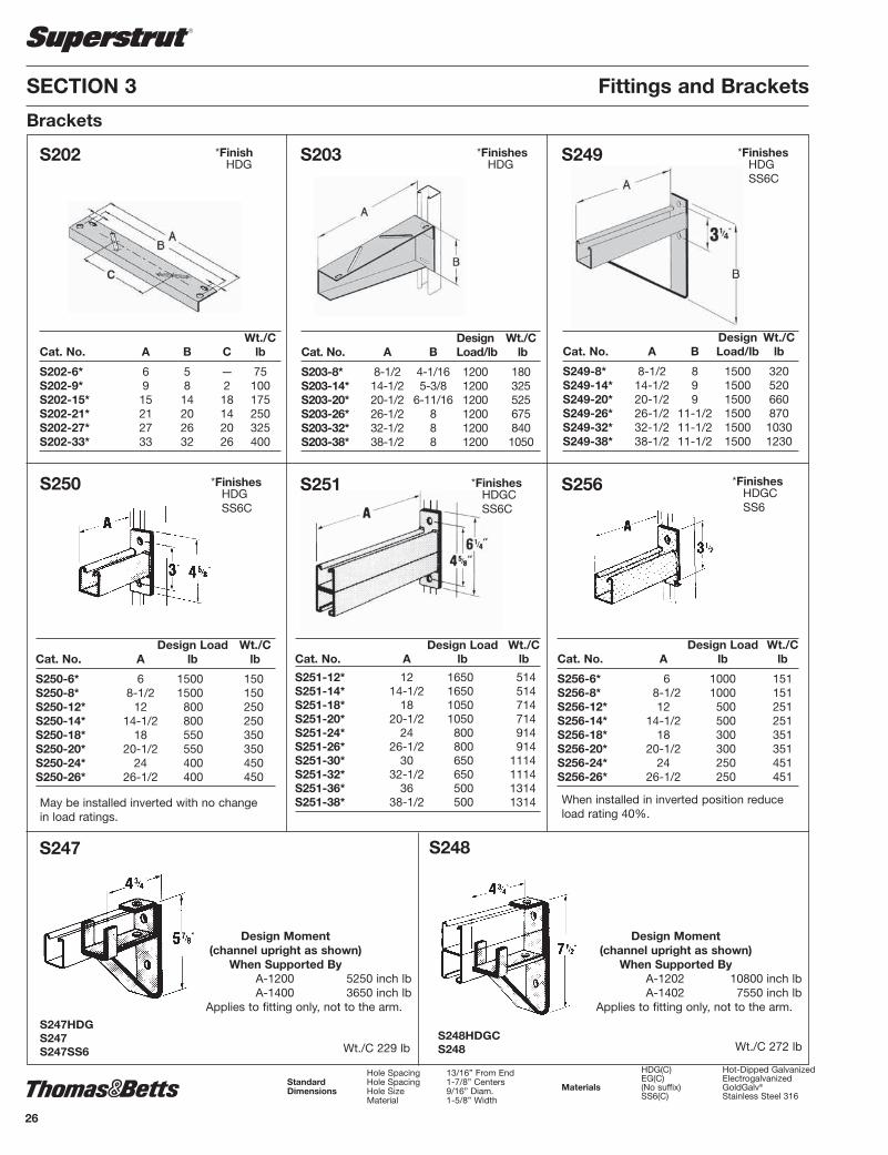
S250 S251
Design Load Wt./CCat. No. A lb lb
S251-12* 12 1650 514S251-14* 14-1/2 1650 514S251-18* 18 1050 714S251-20* 20-1/2 1050 714S251-24* 24 800 914S251-26* 26-1/2 800 914S251-30* 30 650 1114S251-32* 32-1/2 650 1114S251-36* 36 500 1314S251-38* 38-1/2 500 1314
Design Load Wt./CCat. No. A lb lb
S250-6* 6 1500 150S250-8* 8-1/2 1500 150S250-12* 12 800 250S250-14* 14-1/2 800 250S250-18* 18 550 350S250-20* 20-1/2 550 350S250-24* 24 400 450S250-26* 26-1/2 400 450
S256
Design Load Wt./CCat. No. A lb lb
S256-6* 6 1000 151S256-8* 8-1/2 1000 151S256-12* 12 500 251S256-14* 14-1/2 500 251S256-18* 18 300 351S256-20* 20-1/2 300 351S256-24* 24 250 451S256-26* 26-1/2 250 451
S247
Wt./C 229 lb
Design Moment(channel upright as shown) When Supported By A-1200 5250 inch lb A-1400 3650 inch lb
Applies to fitting only, not to the arm.
S248
Wt./C 272 lb
Design Moment(channel upright as shown) When Supported By A-1202 10800 inch lb A-1402 7550 inch lb
Applies to fitting only, not to the arm.
Design Wt./CCat. No. A B Load/lb lb
S249-8* 8-1/2 8 1500 320S249-14* 14-1/2 9 1500 520S249-20* 20-1/2 9 1500 660S249-26* 26-1/2 11-1/2 1500 870S249-32* 32-1/2 11-1/2 1500 1030S249-38* 38-1/2 11-1/2 1500 1230
Hole Spacing 13/16” From EndStandard Hole Spacing 1-7/8” CentersDimensions Hole Size 9/16” Diam. Material 1-5/8” Width
When installed in inverted position reduceload rating 40%.
May be installed inverted with no changein load ratings.
S249S202
Wt./C Cat. No. A B C lb
S202-6* 6 5 — 75S202-9* 9 8 2 100S202-15* 15 14 18 175S202-21* 21 20 14 250S202-27* 27 26 20 325S202-33* 33 32 26 400
S203
Design Wt./CCat. No. A B Load/lb lb
S203-8* 8-1/2 4-1/16 1200 180S203-14* 14-1/2 5-3/8 1200 325S203-20* 20-1/2 6-11/16 1200 525S203-26* 26-1/2 8 1200 675S203-32* 32-1/2 8 1200 840S203-38* 38-1/2 8 1200 1050
*FinishHDG
*FinishesHDGSS6C
*FinishesHDGSS6C
*FinishesHDG
*FinishesHDGCSS6C
*FinishesHDGCSS6
S247HDGS247S247SS6
S248HDGCS248
HDG(C) Hot-Dipped Galvanized EG(C) ElectrogalvanizedMaterials (No suffix) GoldGalv®
SS6(C) Stainless Steel 316
Brackets
26
SSTRUT-E4.pdf 26 1/31/2012 10:30:08 AM

S204HDGCS204
27
Design Uniform Load/lb
A-1200 750A-1400 500
Wt./C 264 lb
S205
Wt./C 264 lb
S217
S218
Wt./C 295 lb
S205HDGCS205
Design Uniform Load/lb
A-1200 750A-1400 650S217HDG
S217S217SS6
Design Uniform Load/lb
A-1200 750A-1400 650
S218HDGS218
S204
Wt./C 174 lb
S222
Wt./C 421 lb
S226
Fittings and Brackets SECTION 3
Brackets
Wt./C 385 lb
Design Uniform Load/lb
A-1200 1000A-1400 750
Design Uniform Load/lb
A-1200 1000A-1400 750
Design Uniform Load/lb
A-1200 750A-1400 500
S222HDGS222
S226HDGS226
For full line of non metallic channel and accessories, please see our new non metallic Cable Tray and Strut Systems Catalogue NMCT-E.
SSTRUT-E4.pdf 27 1/31/2012 10:30:08 AM

SECTION 3 Fittings and Brackets
Wt./C 384 lb Wt./C 400 lb
AP232 AP235
Post Bases
Wt./C 384 lb
AP232SQ
Wt./C 400 lb
AP235SQ
AP232HDGCAP232EGAP232
AP235HDGCAP235EGAP235
AP232SQHDGAP232SQEGAP232SQSS6
AP235SQHDGAP235SQEGAP235SQAP235SQSS6
For full line of non metallic channel and accessories, please see our new non metallic Cable Tray and Strut Systems Catalogue NMCT-E.28
SSTRUT-E4.pdf 28 1/31/2012 10:30:08 AM

29
TR292 TR294
Special Application Fittings and Brackets
Hole Spacing 13/16” From EndStandard Hole Spacing 1-7/8” CentersDimensions Hole Size 9/16” Diam. Material 1/4” Thick
Can be used for series A, E and H channels only.
Standard finish is ElectrogalvanizedFrictionless needle bearings.
Design load: 500 lbSafety factor of 5.
Wt./C 59 lb
Can be used for series A, E and H channels only.
Standard finish isElectrogalvanized
Frictionless needle bearings.Design load: 1000 lb
Safety factor of 5.Wt./C 106 lb
For use over channel splice.Requires 3/8” x 2-1/2” bolt
and nut (not included).Design load: 2000 lb
Wt./C 228 lb
Requires 3/8” x 2-1/2” boltand nut (not included).
Design load: 1000 lbWt./C 104 lb
Wt./CCat. No. A B lb
AN270-1* 2-3/8 6 113AN270-2* 4-3/8 8 151AN270-3* 6-3/8 10 199AN270-4* 8-3/8 12 246AN270-* 10-3/8 14 293
AN270 TS273Track Support
TS272Track Support
*FinishesHDGEG
TS272HDG TS273HDG
Cast aluminum rollers, steel brackets. Designedfor standard saddles. Order separately for eachpair of rollers: - Two 1/2" x 5/16" hex head capscrews and two 1/2" channel nuts. Space to suitO.D. of pipe and wrapping. Wt./C : 300 lb DesignLoad: 2350 lb
HDG(C) Hot-Dipped Galvanized EG(C) ElectrogalvanizedMaterials (No suffix) GoldGalv®
SS6(C) Stainless Steel 316
C728Pipe Roller (Pair)
* Do not usewith back toback Strut
SECTION 3 Fittings and Brackets
For full line of non metallic channel and accessories, please see our new non metallic Cable Tray and Strut Systems Catalogue NMCT-E.
SSTRUT-E4.pdf 29 1/31/2012 10:30:08 AM

30
SSTRUT-E4.pdf 30 1/31/2012 10:30:08 AM

31
Beam Clamps SECTION 4
MaterialMost products are manufactured from hot rolled carbon steel bars or hot rolledstrip steel. Pipe rollers are cast iron.
Design LoadsWhere design loads are indicated, they provide for a safety factor of 3 in conformance with the American Standard Code for Pressure Piping. For more information, see section 8 Engineering Data and Specifications.
Finishes and Special MaterialsHot-Dipped Galvanized (HDGC) is standard for all Superstrut® beam clamps. Thematerial is zinc coated after fabrication providing total product protection on allsurfaces. The fabricated beam clamps are suspended and then dipped into tanksof hot zinc for a prolonged period, creating a coherent bond.
Selected beam clamps can also be available in GoldGalv® (no suffix) or Stainless Steel Type 316 (SS6C). Contact your Regional Sales Office for availabil-ity and minimum quantities.
For full line of non metallic channel and accessories, please see our new non metallic Cable Tray and Strut Systems Catalogue NMCT-E.
SSTRUT-E4.pdf 31 1/31/2012 10:30:08 AM

SECTION 4 Beam Clamps
U501, U502
Furnished completeDesign Load U501 : 2150 lb
U502 : 3000 lb
U504
Wt./C 140 lb Wt./C 270 lb
U505
Wt./CCat. No. For Channel A lb
U501* A1200 A1400 3-3/16 90 B1200 B1400 C1200 B1402
U502* A1202 A1402 4-13/16 100 C1202 H1200
U510 512U U514
U514-A U515 U515-B
1/2" x 1-1/2" set screw included.Order separately one 1/2" x 1-1/2" hexhead cap screw and 1/2" channel nut. Design Load lb Channel 1000 A1200
800 A1400
Order separately one 1/2" x 1-1/2" hexhead cap screw and 1/2" channel nut.
Wt./C 40 lb
Wt./C 91 lbWt./C 95 lbWt./C 59 lb
Can be used with all channels. Can be used with all channels.
Wt./C 75 lb Wt./C 26 lb
*FinishesHDGEGGoldGalv®
SS6C
U504HDGU504EGU504U504SS6
U505HDGU505EGU505
U510HDGCU510EGU510U510SS6
512UHDG512UEG512U
Design Load lb Channel 1000 A1200
800 A1400
U514HDGCU514EGU514U514SS6
3/8" x 1-1/2" set screw included.Design Load 750 lb/pair
U514-AHDGCU514-AEGU514-AU514-ASS6
1/2" x 1-1/2" set screw included.Design Load 1650 lb/pair
U515HDGCU515EGU515U515SS6
For all A series channel.1/2" x 1-1/2" set screw included.Design Load 800 lb
U515BHDGU515BEGU515BU515BSS6
For all B series channel.1/2" x 1-1/2" set screw included.Design Load 800 lb
HDG(C) Hot-Dipped Galvanized EG(C) ElectrogalvanizedMaterials (No suffix) GoldGalv®
SS6(C) Stainless Steel 316
Beam Clamps for Mounting Channel
32
SSTRUT-E4.pdf 32 1/31/2012 10:30:09 AM

33
F
A
9/16” Dia.
Beam Clamps SECTION 4
U520U521U522
A597
Design Channel Wt./C Load
Cat. No. Series lb lb/ea. A597* A 108 800
Nuts, cap screws andset screws included.
Design Flange Wt./C Load
Cat. No. Width A lb lb
U520* 2-3/8 - 4-1/2 8-3/4 328 2000U521* 3-3/4 - 5-3/4 10 343 1300U522* 5-5/8 - 7-5/8 11-7/8 353 900
U544Single Adjusting Screw End Cap Set
Should be orderedas one set.
Wt./C 44 lb
Should be orderedin multiples of two (2).
Wt./C 39 lb
U543Adjusting Screw End Caps
*FinishesGoldGalv®
EG
U543HDGU543EGU543
*FinishesHDGCSS6
DesignCat. A F Wt./C Loadno. in. in. lbs lbs
U570-1* 1-1/2 4 to 9 240 800 U570-2* 1-1/2 7 to 17 300 800
*FinishHDGC
Beam Clamps for Mounting Channel
HDG(C) Hot-Dipped Galvanized EG(C) ElectrogalvanizedMaterials (No suffix) GoldGalv®
SS6(C) Stainless Steel 316
U570-1U570-2
U544EG
For full line of non metallic channel and accessories, please see our new non metallic Cable Tray and Strut Systems Catalogue NMCT-E.
SSTRUT-E4.pdf 33 1/31/2012 10:30:09 AM

SECTION 4 Beam Clamps
U562Beam ClampOptional Use ofU562HDG Beam Clamp
E146 square nut order separately.1/2" set screw included.
Rod Wt./C Design Load Size lb lb
1/2 80 800
Rod Wt./C Design Load Size lb lb
1/2 80 500
US562Beam ClampwithSwing Hanger
U563Beam ClampOptional Use of U563HDG Beam Clamp
US563Beam Clamp with Swing Hanger
3/8" set screw included.
Rod Wt./C Design Load Size lb lb
3/8 50 400
For 20° swivel application use ES-145-1/2 nut.
Rod Wt./C Design Load Size lb lb
3/8 33 400
Rod Wt./C Design Load Size lb lb
3/8 33 240
UM562BeamClamp
E146 square nut order separately.1/2" set screw included.
Rod Wt./C Design Load Size lb lb
1/2 100 1200
For 20° swivel application use ES-145-1/2 nut.
U569Beam Clamp
A570Beam Clamp with Safety Rod
Flange width 4" min. - 8" max.For use with 3/8” rod see U-569. A Wt./C Design
Cat. No. Size lb Load lb
A570HDG 1/2 220 500
3/8"
3/8"
Maximum flange width 5". A Wt./C Design
Cat. No. Size lb Load lb
U569 3/8 150 400
U562HDGU562EGU562U562SS6
1/2" set screw included.
UM562HDGCUM562EGUM562UM562SS6
US562HDGUS562EGUS562
U563HDGU563EGU563
Square nut order separately3/8" set screw included. 3/8" set screw included.
US563HDGUS563
U569HDGU569
HDG(C) Hot-Dipped Galvanized EG(C) ElectrogalvanizedMaterials (No suffix) GoldGalv®
SS6(C) Stainless Steel 316
Beam Clamps for Hanging Rod
1/2" set screw included. Rod Wt./C Design Load Size lb lb
1/2 113 800
34
SSTRUT-E4.pdf 34 1/31/2012 10:30:09 AM

35
Beam Clamps SECTION 4
Rod Dimensions Design Size in. Wt./C LoadCat. No. A B C lb lb
C775L-3/8EG 3/8 3/8 3/8 3/4 38 400C775L-1/2EG 1/2 3/8 3/8 3/4 39 500C775L-5/8EG 5/8 1/2 1/2 3/4 60 550C775L-3/4EG 3/4 5/8 5/8 3/4 69 600C775L-7/8EG 7/8 3/4 3/4 1 184 900
M775L-3/8EG 3/8 3/8 3/4 1-3/4 27 400M775L-1/2EG 1/2 1/2 3/4 1-3/4 35 400M775L-5/8EG 5/8 5/8 3/4 2 52 440M775L-3/4EG 3/4 3/4 3/4 2 63 500
C775L / M775LClamp with Lock Nut
U560Heavy DutyBeam Clamp
U564Heavy Duty Beam Clamp
Design Wt./C LoadCat. No. A B C lb lb
U564-3/8* 3/8 1/8 3/8 x 2-3/4 109 1300U564-1/2* 1/2 1/4 1/2 x 2-3/4 201 3150U564-5/8* 5/8 1/4 1/2 x 2-3/4 201 3150
U568Beam Clamp Safety Strap
U568Beam Clamp Safety Strap
For U562 and UM562 beam clamp.
Beam Flange Wt./C
Cat. No. Width A lb
U568-3EG 6 9 25U568-4EG 9 12 33U568-5EG 12 15 42
For U563 beam clamp.
Beam Flange Wt./CCat. No. Width A lb
U568-1EG 6 8 18U568-2EG 9 11 28
U568Beam Clamp Safety Strap
For U560 and U564 beam clamp.
Beam Flange Wt./CCat. No. Width A lb
U568-6EG 6 9 24U568-7EG 9 12 31U568-8EG 12 15 44
16 gauge material 16 gauge material 16 gauge material
*FinishesGoldGalv®
EG
*FinishesGoldGalv®
EG
Standard Finish - Electrogalvanized (EG) Malleable Iron (M775L)Carbon Steel (C775L)
Beam Clamps for Hanging Rod
HDG(C) Hot-Dipped Galvanized EG(C) ElectrogalvanizedMaterials (No suffix) GoldGalv®
SS6(C) Stainless Steel 316
B C
AM775LC775L
Complies to Specification MSS SP69, Type 23.
Design Wt./C LoadCat. No. A B C lb lb
U560-1/4* 1/4 1/8 3/8 x 1-1/2 67 1050U560-3/8* 3/8 1/8 3/8 x 1-1/2 67 1050U560-1/2* 1/2 1/4 1/2 x 1-1/2 130 2650U560-5/8* 5/8 1/4 1/2 x 1-1/2 130 2650
SSTRUT-E4.pdf 35 1/31/2012 10:30:09 AM

Without Bolt With BoltCat. Fig. Cat. Fig. Rigid Conduit Qty. perNo. No. No. No. EMT or Pipe Box
6H0 1 6H0-B 2 1/2” 3/8”-1/2” 1006H0-T 3 6H0-TB 4 1/2” 3/8”-1/2” 1006H1 1 6H1-B 2 3/4” 3/4” 1006H1-T 3 6H1-TB 4 3/4” 3/4” 1006H2 1 6H2-B 2 1” 1” 100
6H2-TB 4 1” 1” 1006H2 1/2 1 6H2 1/2B 2 1-1/4” - 100
6H2 1/2-TB 4 1-1/4” - 1006H3-SC 1 6H3-B 2 1-1/2” 1-1/4” 100
6H3-TB 4 1-1/2” 1-1/4” 1006H4 1 6H4-B 2 - 1-1/2” 100
6H4-TB 4 - 1-1/2” 1006H5 1 6H5-B 2 2” 2” 100
6H5-TB 4 2” 2” 1006H6 1 6H6-B 2 2-1/2” 2-1/2” 1006H7 1 6H7-B 2 3” 3” 1006H8 1 6H8-B 2 3-1/2” 3-1/2” 1006H9 1 6H9-B 2 4” 4” 100
Standard Finish - Electrogalvanized (no suffix). Use SS suffix for Stainless Steel.Load rating: 500 lb with a safety factor of 3. (For weight per 100 see page 46)
SECTION 4 Beam Clamps
500SC, 502, 503SC, 507,508, 509, 510, 511Beam Clamp
Base Dim. De sign Tapped in. Jaw Wt./C LoadCat. No. Holes A B Opening lb lb
500SC 1/4 - 20 1 1-1/4 15/16 18 450502 3/8 - 16 2 2 1 92 1300503SC 1/2 - 13 2-5/8 2-1/2 1 164 1300507 1/2 - 13 2-1/2 2-3/8 1-3/8 165 1700508 1/2 - 13 2-1/2 2-3/8 2-1/8 184 1700509 10 - 24 1 1-1/4 15/16 22 375510 1/4 - 20 27/32 1-1/8 5/8 15 400511 10 - 24 27/32 1-1/8 5/8 15 400
6H Series in combination with 500 series Beam ClampConduit and Pipe Hanger
Features• Accommodates 1/2” through 4” EMT or rigid conduit• Can be used for either vertical or horizontal installation• 6H-TB Series is threaded so there are less parts to handle or drop• Installs easily with a screwdriver
6H Serieswithout bolt
Fig. 1
6H--B Serieswith bolt and hex nut
Fig. 2
6H-T Threaded Seriesthreaded without bolt
Fig. 3
6H-TB Threaded Seriesthreaded with bolt
Fig.4
Standard Finish -Electrogalvanized (no suffix)
Beam Clamps for Hanging Rod
36
SSTRUT-E4.pdf 36 1/31/2012 10:30:09 AM

37
Conduit Max. Flange Dim. Wt./CCat. No. Size Thickness A lb
U571 1/2 1 1-3/4 36 3/4 3/4 1-3/4 36 1 1/2 1-3/4 36
U572 3/4 1-1/2 2-1/2 59 1 1-1/4 2-1/2 59 1-1/4 1 2-1/2 59 1-1/2 5/8 2-1/2 59
U571U572Conduit Clamp
Beam Clamps SECTION 4
For attaching 1/2" thru 1-1/2" conduit tobeam, channel, angle or column. Securesconduit to the support parallel or at rightangles to it.
5/16" set screw12 gauge material
Standard Finish - GoldGalv ®
Wt./C 38 lb
• Malleable Iron• For mounting pipe or conduit at right angles to
the beam• Use SS316 suffix for 316 Stainless Steel• Use HDG suffix for Hot-Dipped Galvanized
• Malleable Iron• For mounting pipe or conduit vertically across
the beam• Use HDG suffix for Hot-Dipped Galvanized• CSA Certified
• Malleable Iron• For mounting pipe or conduit parallel
to the beam• Use SS316 suffix for 316 Stainless Steel• Use HDG suffix for Hot-Dipped Galvanized
Pipe SupportsThree types of pipe clamps are available to provide right angle, vertical and parallel attachment to a beam. Types RC, EC and PC are malleable iron clamps with an edge that grips the structural member for maximum holdingpower when tightened.
Type RCS clamps are all steel, providing two bearing surfaces for strong attachment for mounting pipe or conduit at right angles to the beam.
All parts are electrogalvanized (no suffix) including the threads. The clamps aredesigned for clamping to a wide variety of beam thicknesses and tapers. Can beinstalled using only a wrench.
Dimensions in inches
Cat O.D. of Nom.No. Conduit Conduit or Std. Wt./C& Size or Pipe Pipe Size Ctn. lb
RCS-3/8 .675 3/8 50 31RCS-1/2 .840 1/2 50 34RCS-3/4 1.050 3/4 50 39RCS-1 1.315 1 50 42RCS-1-1/4 1.660 1-1/4 50 43RCS-1-1/2 1.900 1-1/2 50 60RCS-2 2.375 2 50 72
RC-1/2 .840 1/2 50 36RC-3/4 1.050 3/4 50 43RC-1 1.315 1 50 49RC-1-1/4 1.660 1-1/4 50 51RC-1-1/2 1.900 1-1/2 50 54RC-2-SC 2.375 2 50 76RC-2-1/2 2.875 2-1/2 25 107RC-3 3.500 3 25 116RC-3-1/2 4.000 3-1/2 25 134RC-4-SC 4.500 4 20 158
EC-1/2 .840 1/2 50 69EC-3/4 1.050 3/4 50 78EC-1 1.315 1 25 83EC-1-1/4 1.660 1-1/4 25 108EC-1-1/2 1.900 1-1/2 25 112EC-2 2.375 2 25 140EC-2-1/2 2.875 2-1/2 10 183EC-3 3.500 3 10 203
PC-3/8 .675 3/8 50 32PC-1/2 .840 1/2 50 53PC-3/4 1.050 3/4 50 53PC-1 1.315 1 50 61PC-1-1/4 1.660 1-1/4 25 79PC-1-1/2 1.900 1-1/2 25 56PC-2 2.375 2 25 116PC-2-1/2 2.875 2-1/2 25 148PC-3 3.500 3 10 175PC-3-1/2 4.00 3-1/2 10 199PC-4 4.500 4 10 224
Pipe Supports
Type RC and RCS
Type EC
Type PC
Beam Clamps for Mounting Pipe and Conduit
SSTRUT-E4.pdf 37 1/31/2012 10:30:09 AM

Rod Hole Overall Wt./CCat. No. Size Size Dimensions lb
C781-3/8* 3/8 7/16 3 x 3 x 3/16 27C781-1/2* 1/2 9/16 3 x 3 x 3/16 27C781-5/8* 5/8 11/16 3 x 3 x 1/4 47C781-3/4* 3/4 13/16 3 x 3 x 1/4 42C781-7/8* 7/8 15/16 4 x 4 x 3/8 85C781-1* 1 1-1/8 4 x 4 x 3/8 160
C781Square Washer
Used for beam applications.For channel applications use AB241.
M742RCeiling Flange
SECTION 4 Beam Clamps
540Side Beam Hanger Clip
542Side BeamHanger Clip
S541Swing Connector
Wt./CCat. No. A B C D lb
540-3/8* 7/16 1-7/8 1/4 7/8 38540-1/2* 9/16 1-7/8 1/4 1-5/8 36540-5/8* 11/16 2-1/2 3/8 2 84540-3/4* 13/16 2-1/2 3/8 2 113
Cat. No. Rod Size Wt./C lb
S541-3/8 3/8 31
3/8" x 1-3/4" bolt,nut and clevisincluded.
Design Load Wt./CCat. No. Rod Size lb lb
542-3/8 3/8 610 35542-1/2 1/2 1000 38
Standard Finish - GoldGalv®
For 3/8” and 1/2” rods.
*FinishesBHDGEGSS6
Rod Wt./CCat. No. Size lb
M742R-3/8* 3/8 16M742R-1/2* 1/2 16
*FinishesBEG
Standard Finish - GoldGalv®
For use with wood beam.
*FinishesBEGGoldGalv®
Beam Fittings
HDG(C) Hot-Dipped GalvanizedMaterials EG(C) Electrogalvanized (No suffix) GoldGalv®
SS6(C) Stainless Steel 316 B Bare
38
SSTRUT-E4.pdf 38 1/31/2012 10:30:09 AM

39
Standard Finish - GoldGalv®
For use with wood beam.
U577Clevis and Swing Connector
U576Hanger Clevis
U579Ceiling Flange
Wt./CCat. No. A lb
U579-3/8 3-1/2 30U579-1/2 4-1/4 50
Standard Finish - GoldGalv®
Malleable IronNuts and wood screws not included.Mounting holes 13/32"
Material Hole ThicknessWt./CCat. No. A B lb
U576-3/8 7/16 3/16 27U576-1/2 9/16 3/16 27
Standard Finish - GoldGalv®
For rods up to 1/2"Mounting holes 7/16" di am e ter.For use with wood beam.
Cat. No. Rod Size Wt./C lb U577-1/2 1/2 69
HDG(C) Hot-Dipped GalvanizedMaterials EG(C) Electrogalvanized (No suffix) GoldGalv®
SS6(C) Stainless Steel 316 B Bare
Beam Clamps SECTION 4Beam Fittings
SSTRUT-E4.pdf 39 1/31/2012 10:30:09 AM

40
SSTRUT-E4.pdf 40 1/31/2012 10:30:09 AM

41
Pipe Straps, Pipe Clamps and Hangers SECTION 5
MaterialMost products are manufactured from hot rolled carbon steel bars or hot rolledstrip steel. Pipe rollers are cast iron.
Design LoadsWhere design loads are indicated, they provide for a safety factor of 3 in conformance with the American Standard Code for Pressure Piping.
Hanger DesignPipe hangers are of advanced design to be user friendly.
Finishes and Special MaterialsThe standard finish is Electrogalvanized (EGC) or GoldGalv®. Some products areoffered in Aluminum and Stainless Steel where noted.
For full line of non metallic channel and accessories, please see our new non metallic Cable Tray and Strut Systems Catalogue NMCT-E.
SSTRUT-E4.pdf 41 1/31/2012 10:30:09 AM

SECTION 5 Pipe Straps, Pipe Clamps and Hangers
O.D. of pipe Rigid EMT Wt./C. StdCat. No. in. mm Cond. Cond. lb Pack
701-045PG .36-.45 9-11.5 — — 9 10701-055PG .46-.55 11.5-14 — — 10 10701-065PG .56-.65 14-17 — — 11 10701-075PG .66-.75 17-19.5 — 1/2 13 10701-088PG .76-.88 19.5-22.5 1/2 — 15 10701-100PG .89-1.00 22.5-25.4 — 3/4 16 10701-113PG 1.01-1.13 25.5-29 3/4 — 17 10701-126PG 1.14-1.26 29-32 — 1 18 10701-140PG 1.27-1.40 32-36 1 — 18 10701-153PG 1.41-1.53 36-39 — 1-1/4 19 10701-167PG 1.54-1.67 39-42.5 1-1/4 — 20 10701-180PG 1.68-1.80 42.5-46 — 1-1/2 23 10701-193PG 1.81-1.93 46-49 1-1/2 — 26 10701-204PG 1.93-2.04 49-52 — — 30 10701-225PG 2.10-2.25 53-57.5 — 2 32 10701-237PG 2.26-2.37 57.5-60 2 — 34 10701-245PG 2.33-2.45 59.95-62.5 — — 36 10701-257PG 2.46-2.57 62.5-65.5 — — 38 10701-287PG 2.75-2.87 70-73 2-1/2 2-1/2 40 10701-294PG 2.88-2.94 73-75 — — 42 10701-306PG 2.95-3.06 75-78 — — 42.5 10701-319PG 3.07-3.19 78-81 — — 43 10701-350PG 3.36-3.50 85.5-89 3 3 45 10701-356PG 3.51-3.56 89-90 — — 46 10701-379PG 3.70-3.79 94-96.5 — — 48 10701-400PG 3.80-4.00 96.5-101.5 3-1/2 3-1/2 49 10701-450PG 4.25-4.50 108-114 4 4 70 10701-556PG 5.25-5.56 121-141 5 5 75 5701-665PG 6.25-6.65 146-170 6 6 80 5701-876PG 8.50-8.75 197-222 8 8 85 5
701O.D. Pipe and Conduit ClampMachine screw and nut included.
Standard Finishes and MaterialsPG = Pregalvanized (i.e. 701-045PG)AL = Aluminum (i.e. 701-045AL)
with zinc plated hardwareSS6 = Stainless Steel Type 316 (i.e. 701-045SS6)FG = Fiberglass (in conduit sizes 1/2 to 4”)
703Universal Clamp
EMT/ Conduit Material WT./C Std.Cat. No. Rigid O.D. Thickness lb Ctn.
703-1/2EG 1/2 .706 - .840 16 ga. 400 100703-3/4EG 3/4 .932 - 1.050 14 ga. 550 100703-1EG 1 1.163 - 1.315 14 ga. 550 100703-1-1/4EG 1-1/4 1.508 - 1.660 14 ga. 800 50703-1-1/2EG 1-1/2 1.738 - 1.900 14 ga. 800 50703-2EG 2 2.195 - 2.375 14 ga. 800 50
Standard Finishes -GoldGalv® (i.e.) 703-1/2Electrogalvanized (EG suffix) (i.e.) 703-1-1/2EG
One size fits both Rigid and Electric Metal Tubing (EMT).Individually assembled with screw and nut.
Conduit and Cable Clamps
42
SSTRUT-E4.pdf 42 1/31/2012 10:30:09 AM

43
Pipe Straps, Pipe Clamps and Hangers SECTION 5
Design Load 3
Design Load 1
Design Load 2
Quick Clamp II
Dimension A Dimension ACat. EMT Rigid Conduit Quantity Wt./CNo. in. (mm) in. (mm) per Box lb
TBQC050 1-5/16 (33.5) 1-1/4 (31.5) 100 10TBQC075 1-3/4 (44.5) 1-11/16 (43) 100 12TBQC100 1-13/16 (46) 1-3/4 (44.5) 100 13TBQC125 2-1/8 (54) 2 (51) 50 15TBQC150 2-3/8 (60.5) 2-3/16 (55.5) 50 16TBQC200 2-5/8 (66.5) 2-1/2 (63.5) 50 19TBQC250 3-1/16 (78) 3-1/16 (78) 25 29TBQC300 3-11/16 (93.5) 3-11/16 (93.5) 25 34TBQC350 4-3/16 (106.5) 4-3/16 (106.5) 25 38TBQC400 4-11/16 (119) 4-11/16 (119) 25 42
Ordering information
A
Design Load 1 has a safety factor of 4. DesignLoads 2 and 3 have asafety factor of 1.
Design Load 1 Design Load Design Load Static Load Limit 2 3
lb (kg) lb (kg) lb (kg)
200 (90) 50 (23) 50 (23)200 (90) 50 (23) 50 (23)200 (90) 50 (23) 50 (23)200 (90) 50 (23) 50 (23)200 (90) 50 (23) 50 (23)200 (90) 50 (23) 50 (23)350 (158) 50 (23) 50 (23)350 (158) 50 (23) 50 (23)350 (158) 50 (23) 50 (23)350 (158) 50 (23) 50 (23)
Loading Data
Cobra Ordering information
Static LoadCat. EMT Rigid Con. Cable O.D. Limit (lb) Safety Qty Wt./CNo Trade Size Trade Size Range (in.) Factor = 4 per Box lb
CPC050 1/2 1/2 0.650 - 0.890 200 100 10CPC075 3/4 3/4 0.860 - 1.110 200 100 12CPC100 1 1 1.100 - 1.400 200 100 14CPC125 1 1/4 1 1/4 1.400 - 1.725 200 50 16CPC150 1 1/2 1 1/2 1.690 - 1.980 200 50 18CPC200 2 2 1.980 - 2.576 200 50 24CPC250 2 1/2 2 1/2 2.576 - 3.060 350 25 36CPC300 3 3 3.060 - 3.626 350 25 42CPC350 3 1/2 3 1/2 3.626 - 4.126 350 25 46CPC400 4 4 4.126 - 4.626 350 25 50
Standard material is commercial-grade, bright electrogalvanized steel. Stainlesssteel 316L is also available; addthe suffix “SS6” to catalogue no.(i.e.: CPC050SS6). Stainless steelbolt head is hexagonal and slotted only. Not available in aluminum.
King Cobra
Cat. EMT Rigid Con. Cable O.D. Qty Wt./CNo Trade Size Trade Size Range (in.) per Box lb
LKCPC050 1/2 1/2 0.650 - 0.890 100 15LKCPC075 3/4 3/4 0.860 - 1.110 100 16LKCPC100 1 1 1.100 - 1.400 50 19LKCPC125 1 1/4 1 1/4 1.400 - 1.725 50 23LKCPC150 1 1/2 1 1/2 1.690 - 1.980 50 27LKCPC200 2 2 1.980 - 2.576 50 38LKCPC250 2 1/2 2 1/2 2.576 - 3.060 25 44LKCPC300 3 3 3.060 - 3.626 25 53LKCPC350 3 1/2 3 1/2 3.626 - 4.126 25 58LKCPC400 4 4 4.126 - 4.626 25 66
Design Load 3
Design Load 1
Design Load 2
Ordering information
A
Design Load 1 Design Load Design Load Static Load Limit 2 3
lb (kg) lb (kg) lb (kg)
350 (159) 50 (23) 50 (23)350 (159) 50 (23) 50 (23)350 (159) 50 (23) 50 (23)350 (159) 50 (23) 50 (23)350 (159) 50 (23) 50 (23)350 (159) 50 (23) 50 (23)350 (159) 50 (23) 50 (23)450 (204) 50 (23) 50 (23)450 (204) 50 (23) 50 (23)450 (204) 50 (23) 50 (23)
Loading Data
Conduit and Cable Clamps
43-E.pdf 1 2/15/2012 10:15:06 AM
SECTION 5 Pipe Straps, Pipe Clamps and Hangers
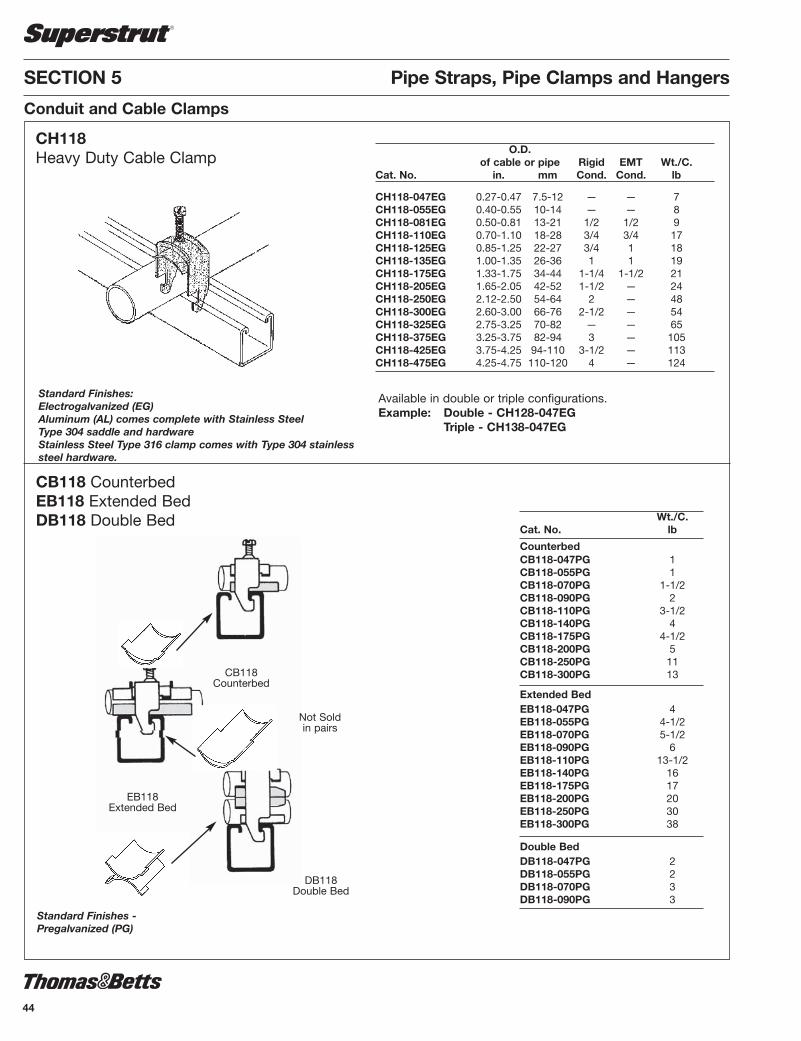
CB118Counterbed
EB118Extended Bed
Not Soldin pairs
O.D.of cable or pipe Rigid EMT Wt./C.
Cat. No. in. mm Cond. Cond. lb
CH118-047EG 0.27-0.47 7.5-12 — — 7CH118-055EG 0.40-0.55 10-14 — — 8CH118-081EG 0.50-0.81 13-21 1/2 1/2 9CH118-110EG 0.70-1.10 18-28 3/4 3/4 17CH118-125EG 0.85-1.25 22-27 3/4 1 18CH118-135EG 1.00-1.35 26-36 1 1 19CH118-175EG 1.33-1.75 34-44 1-1/4 1-1/2 21CH118-205EG 1.65-2.05 42-52 1-1/2 — 24CH118-250EG 2.12-2.50 54-64 2 — 48CH118-300EG 2.60-3.00 66-76 2-1/2 — 54CH118-325EG 2.75-3.25 70-82 — — 65CH118-375EG 3.25-3.75 82-94 3 — 105CH118-425EG 3.75-4.25 94-110 3-1/2 — 113CH118-475EG 4.25-4.75 110-120 4 — 124
CH118 Heavy Duty Cable Clamp
Wt./C.Cat. No. lb
CounterbedCB118-047PG 1CB118-055PG 1CB118-070PG 1-1/2CB118-090PG 2CB118-110PG 3-1/2CB118-140PG 4CB118-175PG 4-1/2CB118-200PG 5CB118-250PG 11CB118-300PG 13
Extended BedEB118-047PG 4EB118-055PG 4-1/2EB118-070PG 5-1/2EB118-090PG 6EB118-110PG 13-1/2EB118-140PG 16EB118-175PG 17EB118-200PG 20EB118-250PG 30EB118-300PG 38
Double BedDB118-047PG 2DB118-055PG 2DB118-070PG 3DB118-090PG 3
CB118 CounterbedEB118 Extended BedDB118 Double Bed
Available in double or triple configurations.Example: Double - CH128-047EG
Triple - CH138-047EG
DB118Double Bed
Standard Finishes - Pregalvanized (PG)
Standard Finishes: Electrogalvanized (EG)Aluminum (AL) comes complete with Stainless Steel Type 304 saddle and hardwareStainless Steel Type 316 clamp comes with Type 304 stainlesssteel hardware.
Conduit and Cable Clamps
44
SSTRUT-E4.pdf 44 1/31/2012 10:30:09 AM

45
Pipe Straps, Pipe Clamps and Hangers SECTION 5
Conduit and Cable Clamps
Tubing Standard PipeAssembly Tube Wt./C Assembly Nominal Std. Wt./CCat. No. O.D. lb Cat. No. Pipe Size Ctn. lb
A716-1/4 1/4 10 P716-1/4 1/4 25 10A716-3/8 3/8 14 P716-3/8 3/8 25 14A716-1/2 1/2 16 P716-1/2 1/2 25 16A716-5/8 5/8 16 P716-3/4 3/4 25 18A716-3/4 3/4 18 P716-1 1 25 22A716-7/8 7/8 18 P716-1-1/4 1-1/4 25 27A716-1 1 22 P716-1-1/2 1-1/2 10 36A716-1-1/8 1-1/8 24 P716-2 2 10 43A716-1-1/4 1-1/4 27 P716-2-1/2 2-1/2 10 49A716-1-3/8 1-3/8 27 P716-3 3 10 60A716-1-1/2 1-1/2 36 P716-3-1/2 3-1/2 10 62A716-1-5/8 1-5/8 37 P716-4 4 10 94A716-1-3/4 1-3/4 37 - - 10A716-1-7/8 1-7/8 43 - - 10A716-2 2 43 - - 10A716-2-1/8 2-1/8 44 - - 10A716-2-3/8 2-3/8 49 - - 10A716-2-5/8 2-5/8 53 - - 10A716-3-1/8 3-1/8 62 - - 10A716-4-1/8 4-1/8 94 - - 10
Copper and Copper NominalAssembly Steel Tubing Water Pipe Pipe Std. Wt./CCat. No. O.D. (nom.) Size Ctn. lb
U716-1/4 1/4 - - 25 3U716-3/8 3/8 1/4 - 25 4U716-1/2 1/2 3/8 1/4 25 6U716-5/8 5/8 1/2 3/8 25 6U716-3/4 3/4 5/8 - 25 7U716-7/8 7/8 3/4 1/2 25 7U716-1 1 - - 25 8U716-1-1/8 1-1/8 1 - 25 8U716-1-1/4 1-1/4 - - 10 17U716-1-3/8 1-3/8 1-1/4 10 20U716-1-1/2 1-1/2 - - 10 22U716-1-5/8 1-5/8 1-1/2 - 10 23U716-2 2 - - 10 41U716-2-1/8 2-1/8 - - 10 41U716-2-3/8 2-3/8 - - 10 44
• Guides, protects, and uniformly spaces line runs.Low cost, time saving method of attaching tubingand hose to equipment.
• Cushion is built to withstand the effects of most oils,chemical and industrial cleaning compounds, intemperatures from -45°C to 121°C (-50°F to 275°F).Interlock edge insures cushion remains in place.
• Attached with two standard fasteners to any flatsurface, this clamp eliminates the use of specialchannels, providing a savings in both space require-ments and cost.
• Cushioned clamps reduce vibration, shock, andnoise in fluid systems and eliminates electrolysis.
• Assembly consisting of GoldGalv® finish steel clampwith bolt/locknut and cushion.
• Secure pipes, tubes and hoses for fluid conductors.• Installation is easy and requires no more time than
a simple pipe clamp installation.• Cushion absorbs the shocks and associated vibrations
from fluid surges in tubes, pipes and hoses.• It can handle temperatures from 149°C to -40°C
(300°F to -40°F).• Cushioned Clamp assemblies are available
individually bagged.
Standard Finish – GoldGalv®
A716 Snap•Guard® Cushioned Clamp Tube SeriesP716 Snap•Guard® Cushioned Clamp Pipe Series
Standard Finishes GoldGalv®
Available in Stainless Steel - use SS suffix.(i.e) A716-1SSElectrogalvanized (Silver) - use EG suffix.(i.e) A716-1EG
A716 / P716
U716, U717 Two Hole Cushioned Clamp
U716 / U717
SSTRUT-E4.pdf 45 1/31/2012 10:30:09 AM

SECTION 5 Pipe Straps, Pipe Clamps and Hangers
Conduit and Cable Clamps
MaximumCat. Channel Tie Width Unit Std.No. Size Accom. Qty. Pkg.
TC5363X 1-1/2 & 1-5/8 .301 50 250
INSTALLATION
6H SeriesConduit and Pipe Hanger
Cat. Conduit Size Wt./CNo. Rigid EMT lb
6H0 3/8” - 1/2” 1/2” 56H0-B 3/8” - 1/2” 1/2” 76H0-T 3/8” - 1/2” 1/2” 56H0-TB 3/8” - 1/2” 1/2” 66H1 3/4” 3/4” 66H1-B 3/4” 3/4” 76H1-T 3/4” 3/4” 66H1-TB 3/4” 3/4” 76H2 1” 1” 76H2-B 1” 1” 96H2-1/2 - 1-1/4” 86H2-1/2-B - 1-1/4” 106H3-SC 1-1/4” 1-1/2” 86H3-B 1-1/4” 1-1/2” 106H3-TB 1-1/4” 1-1/2” 106H4 1-1/2” - 176H4-B 1-1/2” - 196H4-TB 1-1/2” - 196H5 2” 2” 246H5-B 2” 2” 266H5-TB 2” 2” 266H6 2-1/2” 2-1/2” 286H6-B 2-1/2” 2-1/2” 306H7 3” 3” 366H7-B 3” 3” 386H8 3-1/2” 3-1/2” 396H8-B 3-1/2” 3-1/2” 416H9 4” 4” 446H9-B 4” 4” 47
6H Series 6H-B Serieswith Bolt and Hex Nut
6H-TBThreaded Series
6H-TThreaded Series
Standard Finish - Electrogal va nized (no suffix)Available in Stainless Steel 304 (SS)
When fastening wire bundles, cables, or hoses to framing channels, you can cut costs considerably by using this mounting base. It is madeof smooth, weather-resistant nylon and designed to protect cable insulation and hoses from the wear or damage that can occur with metalclamps. The mounting base may be used for both indoor or outdoor applications. It installs in the framing channel with a simple push andtwist. It requires no screws, nuts or tools. The mounting base fits all 1-1/2" and 1-5/8" channels regardless of channel depth. Ty-Rap® andTy-Fast® to be ordered separately.
• Installs with a push and twist • Designed for indoor or
outdoor use• Smooth design protects cable
insulation • Takes range of cable diameters
Cable Tie Mounting BasesFor Framing Channel
Features• Accommodates 1/2”
through 4” EMT or rigidconduit
• Can be used for eithervertical or horizontalinstallation
• 6HTB Series have abuilt-in nut so there arefewer parts to handle ordrop
• Installs easily with ascrewdriver
46
SSTRUT-E4.pdf 46 1/31/2012 10:30:09 AM

47
Pipe Straps, Pipe Clamps and Hangers SECTION 5
Conduit and Cable Clamps
Cat. No. Dimensions
Hardwood Depth Weightparaffin imp. in. mm in. mm
W716-3/4PG 3/4 19.0 2-1/8 53.9W716-1PG 1 25.4 2-1/8 53.9W716-1-1/4PG 1-1/4 31.7 2-5/8 66.6W716-1-1/2PG 1-1/2 38.1 2-5/8 66.6W716-1-3/4PG 1-3/4 44.4 3 76.2W716-2PG 2 50.8 3-5/8 92.0W716-2-1/4PG 2-1/4 57.1 3-5/8 92.0W716-2-1/2PG 2-1/2 63.5 4-5/8 117.7W716-2-3/4PG 2-3/4 69.8 4-5/8 117.7W716-3PG 3 76.2 4-5/8 117.7W716-4PG 4 98.0 5-5/8 143.4
Paraffin impregnatedmaple.
Note: Holding clamp is included with W716 maple hardwood clamps.It is not necessary to order 701 Series separately.
1/8”
3.17
1 /8”
3.171/8” 13/8”
1/8”
3.17
15/ 8
”
41.5
7
W716 Maple Hardwood Clamps
U861Maple Cable Clamp
Custom made to your needs
Step 1 Number of holesi.e. U861 1 hole
U862 2 holesU863 3 holes
Step 2 Specify O.D. of cablei.e. 3/4" hole U861 - 0.75
Contact your Regional Sales Office for quotation.
Electrogalvanized hardware included
WS716 Maple Hardwood Saddle
Paraffin impregnated maple.
Cat. No. DimensionsHardwood Depth Width Height
Paraffin Imp. in. mm in. mm in. mm
WS716-3/4 3/4 19.0 3 76.2 1-3/4 44.4WS716-1 1 25.4 3 76.2 1-3/4 44.4WS716-1-1/4 1-1/4 31.7 3-1/2 88.9 2 50.8WS716-1-1/2 1-1/2 38.1 3-1/2 88.9 2 50.8WS716-1-3/4 1-3/4 44.4 4 101.6 2-1/4 57.1WS716-2 2 50.8 4 101.6 2-1/4 57.1WS716-2-1/4 2-1/4 57.1 4-1/2 114.3 2-1/2 63.5WS716-2-1/2 2-1/2 63.5 4-1/2 114.3 2-1/2 63.5WS716-2-3/4 2-3/4 69.8 5 127 2-3/4 69.8WS716-3 3 76.2 5 127 2-3/4 69.8WS716-3-1/4 3-1/4 82.5 5-1/2 139.7 2-3/4 76.2WS716-3-1/2 3-1/2 88.9 5-1/2 139.7 3 76.2WS716-3-3/4 3-3/4 95.2 6 152.4 3-1/4 82.5WS716-4 4 101 6 152.4 3-1/4 82.5WS716-4-1/2 4-1/2 114.3 6-1/2 165.1 3-1/2 88.9WS716-5 5 127 7 177.8 3-3/4 95.2WS716-5-1/2 5-1/2 139.7 7-1/2 190.5 4 101.6WS716-6 6 152.4 8 203.2 4-1/4 107.9WS716-6-1/2 6-1/2 165.1 8-1/2 215.9 4-1/2 114.3WS716-7 7 177.8 9 228.6 4-3/4 120.6To fasten saddle,
use 3/8" X 2" screw bolt.
Standard Finishes -Pregalvanized (PG)Aluminum (AL)
SSTRUT-E4.pdf 47 1/31/2012 10:30:09 AM

SECTION 5 Pipe Straps, Pipe Clamps and Hangers
Conduit and Cable Clamps
AB8803" Porcelain Saddle
AB8814" Porcelain Saddle
Max. Cable Wt./CCat. No. A Diam. lb
AB880 3 3 73AB881 4 4-1/2 104
C755 Porcelain Cable Clamps
Hole Wt./C Cat. No. Size A lb
C755-1A 3/8 1-9/16 50C755-1B 1/2 1-9/16 50C755-1C 5/8 1-9/16 50
C755-2 3/4 2-5/32 91C755-2A 7/8 2-5/32 90C755-2B 1 2-5/32 85
C755-2C 1-1/8 2-5/32 82C755-3 1-1/4 2-5/8 114C755-3A 1-3/8 2-5/8 110
C755-3B 1-1/2 2-5/32 105C755-3C 1-5/8 2-5/8 102C755-4 1-3/4 3-3/4 220
C755-4A 1-7/8 3-3/4 214C755-4B 2 3-3/4 205C755-4C 2-1/8 3-3/4 200
C755-5 2-1/4 4-1/4 260C755-5A 2-3/8 4-1/4 250C755-5B 2-1/2 4-1/4 243
Hole Wt./C Cat. No. Size A lb
C755-5C 2-5/8 4-1/4 240C755-6 2-3/4 4-3/4 250C755-6A 2-7/8 4-3/4 240
C755-6B 3 4-3/4 230C755-6C 3-1/8 4-3/4 220C755-7 3-1/4 5-13/16 340
C755-7A 3-3/8 5-13/16 330C755-7B 3-1/2 5-13/16 318C755-7C 3-5/8 5-13/16 387
C755-8 3-3/4 6-7/8 565C755-8A 3-7/8 6-7/8 550C755-8B 4 6-7/8 535
C755-8C 4-1/8 6-7/8 520C755-8D 4-1/4 6-7/8 490C755-8E 4-3/8 6-7/8 475
C755-8F 4-1/2 6-7/8 460
hole size
A
Standard Finish -GoldGalv® with bronze hardwareAlso fits 1-1/2" wide channel.For minimum order quantities contact customer service.
2b” A
48
SSTRUT-E4.pdf 48 1/31/2012 10:30:09 AM

49
Pipe Straps, Pipe Clamps and Hangers SECTION 5
Conduit and Cable Clamps
C708UShort Strap for Channelor Wall Mount ing
Design Pipe Hole Load Wt./C Size A B Thickness Width Size lb lb
1/2 2-7/8 2 1/8 1-5/8 9/32 650 23 3/4 3-1/16 2-3/16 1/8 1-5/8 9/32 650 26 1 3-3/8 2-1/2 1/8 1-5/8 9/32 650 31 1-1/4 3-11/16 2-13/16 1/8 1-5/8 9/32 650 35 1-1/2 3-15/16 3-1/16 1/8 1-5/8 9/32 650 39
2 5-3/4 4-1/8 1/4 1-5/8 7/16 650 94 2-1/2 6-3/16 4-9/16 1/4 1-5/8 7/16 1000 114 3 6-13/16 5-3/16 1/4 1-5/8 7/16 1000 133 3-1/2 7-5/16 5-11/16 1/4 1-5/8 7/16 1000 152 4 7-13/16 6-3/16 1/4 1-5/8 7/16 1200 176
5 8-7/8 7-1/4 1/4 1-5/8 7/16 1200 198 6 9-15/16 8-5/16 1/4 1-5/8 7/16 1200 246
Standard Finish - GoldGalv®
Example: C708U-1/2No clearance between pipe and channel.
For use with 701 O.D. tubing and pipe clamp. Todetermine 701 clamp size add 1/4" to O.D. tubesize to allow for the Cushioned Strip material.
Order 701 clamp separately.
1/4" markings for fast measuring and cutting.Measurement chart is printed on back of car-ton. 20 feet included in each carton.
Prevent metal to metal contact with the Cush -ioned Strip material. It aids in sound in su la -tion, shock absorption and protects against cor-rosion, distortion and abrasion. CushionedStrip material is designed for optimal usebetween-1°C and 149°C (30°F and 300°F).Cushioned Strip material combined with theSuperstrut 701 pipe strap can handle clampingassignments from 1/4" to 6."
S716Cushioned Strip for Isolation &Vi bra tion Applications
Carbon Steel
1-5/8”
SSTRUT-E4.pdf 49 1/31/2012 10:30:09 AM

SECTION 5 Pipe Straps, Pipe Clamps and Hangers
Conduit and Cable Clamps
Standard
C711“J” Pipe Hanger
A Overall Max. Rec. Approx. Pipe Rod Dimension Bolt Load Wt./C Size Size B C D E F Size G Thickness Width lb lb
1/2 3/8 2-5/8 1-3/4 7/16 1-1/2 1-15/16 1/4 3-5/32 12 ga 3/4 400 18
3/4 3/8 2-7/8 1-7/8 7/16 1-11/16 2-1/8 1/4 3-1/2 12 ga 3/4 400 21 1 3/8 2-15/16 1-15/16 7/16 1-13/16 2-5/16 1/4 3-11/16 12 ga 3/4 400 22
1-1/4 3/8 3-1/4 2 7/16 2-1/16 2-5/8 1/4 4-1/8 12 ga 3/4 400 25 1-1/2 3/8 3-9/16 2-3/16 7/16 2-7/16 2-7/8 1/4 4-5/8 12 ga 3/4 400 27 2 3/8 3-11/16 2-1/8 7/16 2-9/16 3-1/16 1/4 5 12 ga 3/4 400 29
2-1/2 1/2 4-7/16 2-7/16 9/16 3-3/16 3-5/8 3/8 6 12 ga 1-1/4 500 64 3 1/2 4-13/16 2-9/16 9/16 3-1/2 4-1/16 3/8 6-21/32 12 ga 1-1/4 500 72 3-1/2 1/2 5-1/8 2-5/8 9/16 3-3/4 4-3/8 3/8 7-5/16 3/16 1-1/4 500 84
4 5/8 6-1/8 3-3/16 9/16 4-5/8 5-3/16 3/8 8-9/16 3/16 1-1/4 550 138 5 5/8 6-3/4 3-1/4 9/16 5-1/16 5-3/5 3/8 9-23/32 3/16 1-1/4 550 162 6* 3/4 7-3/4 3-9/16 9/16 5-13/16 6-5/8 3/8 11-1/4 3/16 1-3/4 600 249 8* 7/8 9-3/16 3-15/16 9/16 6-15/16 8 3/8 13-11/16 3/16 1-3/4 760 291
*Hangers 6" and over have hole instead of slot.
C727Adjustable Ring
Standard Finishes - GoldGalv®, Electrogalvanized (EG)Complies with Specification MSS SP69, Type 5.Hole provided for side mounting to wall as bracket. Example: C711-1/2
Standard Finish - Pregalvanized (no suffix), Stainless Steel (SS)Carbon steel. For suspension of non-insulated pipe lines. Complies with Specification MSS SP69, Type 10.Example: C727-1/2
Approx.Tube Rod Max. Rec. Wt./CSize Size A B C Thickness Width Load lb
1/2 3/8 3-1/8 2-5/8 1-3/8 16 ga 1 400 9 3/4 3/8 3-1/8 2-1/2 1-1/8 16 ga 1 400 9 1 3/8 3-3/8 2-5/8 1-1/8 16 ga 1 400 9
1-1/4 3/8 3-3/4 2-7/8 1-1/8 16 ga 1 400 101-1/2 3/8 3-7/8 2-7/8 1 16 ga 1 400 11 2 3/8 4-1/4 3 1 16 ga 1 400 12
2-1/2 1/2* 5-3/4 4-1/4 1-5/8 14 ga 1-3/16 600 28 3 1/2* 6 4-1/8 1-1/4 14 ga 1-3/16 600 303-1/2 1/2* 7-3/8 5-1/4 2-1/8 14 ga 1-3/16 600 34
4 5/8* 7-3/8 5 2-5/8 14 ga 1-1/4 1000 37 5 5/8** 9 6-1/8 2-1/4 12 ga 1-1/4 1250 83 6 3/4** 9-3/8 6-1/2 1-7/8 12 ga 1-1/4 1250 95
**3/8" nut is used when NFPA rod sizing is requested.**1/2" nut is used when NFPA rod sizing is requested.
50
SSTRUT-E4.pdf 50 1/31/2012 10:30:09 AM

51
Pipe Straps, Pipe Clamps and Hangers SECTION 5
Pipe Hangers
C710Adjustable Clevis Hanger
CL710Light Duty Adjustable Clevis Hanger
Standard Finishes - GoldGalv®, Electrogalvanized (EG)Complies with Specification MSS SP69, Type 1.Standard Clevis Hanger also available in Stain less SteelExample: C710-1/2EG
Pipe Size of Steel Max. Rec. Wt./C Size Upper Lower A B C D E F Load, lb lb
1/2 1/8x1 1/8x1 3/8 1-11/16 2-1/8 2-1/2 7/8 7/16 610 30 3/4 1/8x1 1/8x1 3/8 1-7/8 2-7/16 2-1/2 1 1/2 610 32 1 1/8x1 1/8x1 3/8 2-1/8 2-13/16 2-1/2 1-1/4 5/8 610 36 1-1/4 1/8x1 1/8x1 3/8 2-9/16 3-7/16 2-1/2 1-3/4 7/8 610 42 1-1/2 1/8x1 1/8x1 3/8 3 4 2-1/2 2-1/8 1-1/16 610 55 2 1/8x1 1/8x1 3/8 3-11/16 4-7/8 2-1/2 2-15/16 1-5/8 610 60
2-1/2 3/16x1-1/4 3/16x1-1/4 1/2 4-11/16 6-1/8 3 3-13/16 2 1130 115 3 3/16x1-1/4 3/16x1-1/4 1/2 4-3/4 6-9/16 3 3-7/8 1-3/4 1130 132 3-1/2 3/16x1-1/4 3/16x1-1/4 1/2 4-15/16 6-15/16 3 4-1/16 1-3/4 1130 156
4 1/4x1-1/4 3/16x1-1/4 5/8 5-9/16 7-13/16 3-1/2 4-1/2 1-15/16 1430 190 5 1/4x1-1/4 3/16x1-1/4 5/8 6-3/16 9 3-1/2 5-1/8 1-3/4 1430 240 6 1/4x1-1/2 3/16x1-1/2 3/4 6-13/16 10-1/8 4 5-5/8 1-7/8 1940 320
8 1/4x1-3/4 3/16x1-3/4 7/8 8-5/16 12-5/8 4-1/4 7 2-1/8 1940 500
Standard Finishes - GoldGalv®, Bare (B), Electrogalvanized (EG),Fiberglass (FG).Carbon SteelUsed on non-insulated, stationary pipelines. A lock nut above the clevis yoke is required for full rated load. Example: CL710-3/8B
Pipe Thickness of Steel Max. Rec. Wt./C Size Upper Lower A B C D E F Load, lb lb
3/8 16 ga x 7/8 16 ga x 7/8 3/8 1-7/8 2-3/16 2-1/2 1-1/4 9/16 150 12 1/2 16 ga x 7/8 16 ga x 7/8 3/8 1-3/4 2-3/16 2-1/2 1-1/8 9/16 150 13 3/4 16 ga x 7/8 16 ga x 7/8 3/8 1-7/8 2-1/4 2-1/2 1-1/4 1/2 250 15 1 16 ga x 7/8 16 ga x 7/8 3/8 2-3/16 2-3/4 2-1/2 1-1/2 3/4 250 18 1-1/4 16 ga x 7/8 16 ga x 7/8 3/8 2-5/8 3-3/8 2-1/2 1-3/4 1 250 20 1-1/2 13 ga x 7/8 13 ga x 7/8 3/8 3 3-7/8 2-1/2 2-1/4 1-3/16 250 30 2 13 ga x 7/8 13 ga x 7/8 3/8 3-9/16 4-3/4 2-1/2 2-13/16 1-5/8 250 38 2-1/2 1/8 x 1-1/4 1/8 x 1-1/4 1/2 4 5-1/2 3 3-1/4 1-3/8 350 80 3 1/8 x 1-1/4 1/8 x 1-1/4 1/2 4-9/16 6-1/2 3 3-9/16 1-1/2 350 89 3-1/2 1/8 x 1-1/4 1/8 x 1-1/4 1/2 5 7 3 4-1/8 1-3/4 350 106 4 3/16 x 1-1/4 1/8 x 1-1/4 1/2 5-1/4 7-1/2 3-1/2 4-1/4 1-7/8 400 146
SSTRUT-E4.pdf 51 1/31/2012 10:30:09 AM

SECTION 5 Pipe Straps, Pipe Clamps and Hangers
Pipe Hangers
M718Split Pipe Ring
Standard Finishes - Bare (B) or Electrogalvanized (EG)Malleable iron.For suspension of non-insulated, stationary pipelines.Example: M718-3/8B Pipe Max. Rec. Wt./C Size A B Load/lb lb
3/8 3/8 13/16 180 10 1/2 3/8 7/8 180 13 3/4 3/8 1 180 14
1 3/8 1-1/8 180 16 1-1/4 3/8 1-5/16 180 22 1-1/2 3/8 1-7/16 180 24
2 3/8 1-11/16 180 31 2-1/2 1/2 2-1/8 300 60 3 1/2 2-7/16 300 74 4 1/2 2-15/16 300 116
C725Medium Pipe Clamp
Standard Finishes - GoldGalv®, Bare (B), Stainless Steel (SS), Electrogalvanized (EG)Carbon steel. For suspension of pipelines where little or no insulation is required.Complies with Specification MSS SP69, Type 23.Example: C725-1/2B
Pipe Max. Rec. Wt./C, lb Size B C D E F H S Load, lb Approx.
1/2 1 7/16 1-5/8 1 5/16 1-1/2 1/8 x 1 500 29 3/4 1-1/8 7/16 1-3/4 1-1/4 5/16 1-3/4 1/8 x 1 500 32
1 1-1/4 7/16 1-13/16 1-1/4 5/16 1-13/16 1/8 x 1 500 33 1-1/4 1-7/16 7/16 2 1-7/16 5/16 2 1/8 x 1 500 38 1-1/2 1-5/8 1/2 2-1/16 1-1/2 5/16 2-1/4 1/8 x 1 715 39
2 2-1/8 9/16 3-1/8 2-1/4 1/2 3 1/4 x 1 1040 117 2-1/2 2-5/16 9/16 3-5/16 2-1/2 1/2 3-1/4 1/4 x 1 1040 128 3 2-3/4 9/16 3-3/4 2-3/4 1/2 3-5/8 1/4 x 1 1040 140
3-1/2 3-7/8 5/8 3-3/4 3 1/2 3-7/8 1/4 x 1 1040 145 4 3-5/16 3/4 4-1/4 3-5/16 5/8 4-1/4 1/4 x 1-1/4 1040 238
6 4-7/8 7/8 5-7/8 5 3/4 5-3/4 3/8 x 1-1/2 1615 542 8 6 1 7 6-1/8 3/4 6-7/8 3/8 x 1-1/2 1615 651 10 7-5/16 1 8-9/16 7-7/16 7/8 8-7/16 1/2 x 2 2490 1360
12 8-1/4 1 9-9/16 8-7/16 7/8 9-3/8 1/2 x 2 2490 1605
Based on the allowable stresses shown in ANSI Code for pressure piping.For sizes 14 to 24, contact Customer Service.
52
SSTRUT-E4.pdf 52 1/31/2012 10:30:09 AM

53
Pipe Straps, Pipe Clamps and Hangers SECTION 5
Pipe Hangers
C720Riser Clamp
Standard Riser
C726Double Bolt Pipe Clamp
Standard Finishes - GoldGalv®, Bare (B), Stainless Steel (SS)Available in sizes 1/2" through 10".Complies with Specification MSS SP69, Type 8.Example: C720-1 1/2B
Pipe Max. Rec. Wt./Ea. Size A Thickness Width Bolt Load, lb Approx.
1/2 9-1/8 3/16 1 3/8 x 1-1/2 220 1.01 3/4 9-1/4 3/16 1 3/8 x 1-1/2 220 1.06 1 9-5/8 3/16 1 3/8 x 1-1/2 220 1.07
1-1/4 9-7/8 1/4 1 3/8 x 1-1/2 250 1.12
1-1/2 10 1/4 1 3/8 x 1-1/2 250 1.20 2 10-1/2 1/4 1 3/8 x 1-1/2 300 1.25
2-1/2 11-1/16 1/4 1 3/8 x 1-1/2 400 1.67
3 11-13/16 1/4 1 3/8 x 1-1/2 500 1.81 3-1/2 13 1/4 1 1/2 x 1-1/2 600 2.12 4 13-1/2 1/4 1 1/2 x 1-1/2 750 2.22
5 14 1/4 1-1/2 1/2 x 1-3/4 1500 3.44 6 15-3/16 1/4 1-1/2 1/2 x 1-3/4 1600 3.65 8 19 3/8 1-1/2 5/8 x 2-1/2 2500 7.24
Pipe Max. Rec. Approx. Size B C D E F H S Load, lb Wt. /C
3/4 1-1/16 5/8 3-3/16 2-1/2 3/8 1-11/16 3/16 x 1 950 66
1 1-1/2 5/8 3-3/4 2-1/2 3/8 2-1/16 3/16 x 1 950 69 1-1/4 1-1/2 3/4 3-11/16 2-7/8 3/8 2-1/4 3/16 x 1 950 75
1-1/2 1-13/16 1-1/16 4-7/8 3-3/4 5/8 2-13/16 1/4 x 1-1/4 1545 181 2 2-1/4 1-1/16 5-11/16 4-11/16 5/8 3-3/16 1/4 x 1-1/4 1545 200
2-1/2 2-5/8 1-1/16 6-1/2 5-3/8 5/8 3-1/2 1/4 x 1-1/4 1545 232
3 2-3/4 1-1/16 6-7/8 6 5/8 3-3/4 1/4 x 1-1/4 1545 258 3-1/2 3 1-1/16 7-1/16 6-3/16 5/8 4 1/4 x 1-1/4 1545 264 4 3-3/8 1-1/16 7-5/8 6-1/2 3/4 4-1/2 3/8 x 2 2500 750
5 3-15/16 1-1/16 8-1/8 7 3/4 5 3/8 x 2 2500 813 6 4-3/4 1-7/16 9-15/16 8-9/16 1 6-1/8 3/8 x 2-1/2 2865 1311 8 5-3/4 1-7/16 10-15/16 9-9/16 1 7-1/8 3/8 x 2-1/2 2865 1467
Standard Finish - Bare (B)Carbon Steel. For the suspension of insulated pipelines.Normally used with weldless eye nut.Example: C726-1/2B
SSTRUT-E4.pdf 53 1/31/2012 10:30:10 AM

SECTION 5 Pipe Straps, Pipe Clamps and Hangers
1650 lb. loadsafety factor 3
Wt./C 61 lb
1650 lb. loadsafety factor 3
Wt./C 72 lb
C749N-1 1/8Seismic BraceStandard Finish - GoldGalv®
All braces have plastisol coating on the flat member.Plastisol insulates against vibration noise transmission and eliminates rattle at the connection points.
C749N-5/8Seismic BraceStandard Finish - GoldGalv®
1650 lb. loadsafety factor 3
Wt./C 56 lb
1650 lb. loadsafety factor 3
Wt./C 74 lb
ES142Standard Finish - GoldGalv®
Seismic bracing rodstiffener connector.
Wt./C 21 lb
Bolt Wt./CCat. No. Dia. lbES-142-1/2 x 1-1/2 1/2 21
C749NSeismic BraceStandard Finish - GoldGalv®
C749N-7/8Seismic BraceStandard Finish - GoldGalv®
Consult Supertrut® seismic Hanger Bulletin (GM141) for additional informationSeismic Bracing
54
54-e.pdf 1 4/19/2012 2:32:51 PM
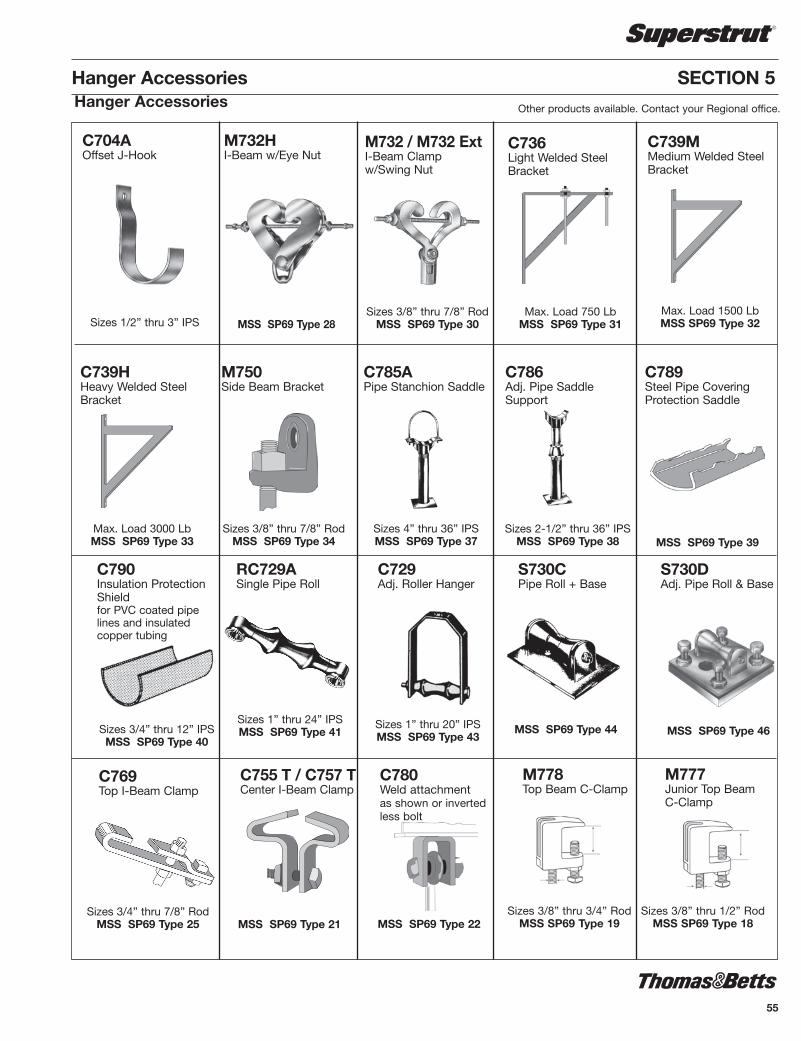
55
Hanger Accessories SECTION 5
C704AOffset J-Hook
Sizes 1/2” thru 3” IPS
M732HI-Beam w/Eye Nut
MSS SP69 Type 28
C739MMedium Welded SteelBracket
C736Light Welded SteelBracket
Max. Load 750 LbMSS SP69 Type 31
M732 / M732 ExtI-Beam Clampw/Swing Nut
Sizes 3/8” thru 7/8” RodMSS SP69 Type 30
Max. Load 3000 LbMSS SP69 Type 33
Sizes 3/8” thru 7/8” RodMSS SP69 Type 34
C789Steel Pipe CoveringProtection Saddle
C786Adj. Pipe SaddleSupport
Sizes 2-1/2” thru 36” IPSMSS SP69 Type 38
C785APipe Stanchion Saddle
Sizes 4” thru 36” IPSMSS SP69 Type 37
M750Side Beam Bracket
C739HHeavy Welded SteelBracket
Max. Load 1500 LbMSS SP69 Type 32
MSS SP69 Type 39
Other products available. Contact your Regional office.Hanger Accessories
Sizes 3/4” thru 12” IPSMSS SP69 Type 40
MSS SP69 Type 44
S730CPipe Roll + Base
C729Adj. Roller Hanger
Sizes 1” thru 20” IPSMSS SP69 Type 43
RC729ASingle Pipe Roll
Sizes 1” thru 24” IPSMSS SP69 Type 41
C790Insulation ProtectionShieldfor PVC coated pipelines and insulatedcopper tubing
MSS SP69 Type 46
S730DAdj. Pipe Roll & Base
Sizes 3/4” thru 7/8” RodMSS SP69 Type 25
C769Top I-Beam Clamp
MSS SP69 Type 22
C780Weld attachmentas shown or invertedless bolt
C755 T / C757 TCenter I-Beam Clamp
MSS SP69 Type 21Sizes 3/8” thru 1/2” Rod
MSS SP69 Type 18Sizes 3/8” thru 3/4” Rod
MSS SP69 Type 19
M778Top Beam C-Clamp
M777Junior Top BeamC-Clamp
SSTRUT-E4.pdf 55 1/31/2012 10:30:10 AM

56
SSTRUT-E4.pdf 56 1/31/2012 10:30:10 AM

57
MAXIMUM NUMBER OF WIRES Raceway With or without Wire KO Size A1200 B1200 E1200 AWG A1400 B1400 C1200 H1200 A B A B A B A B
14 6 10 4 6 5 10 6 10 12 6 10 3 6 4 10 6 10 10 5 8 4 6 5 8 8 4 6 3 4 4 6 6 2 3 2 2 2 3
Surface Raceway and Lighting Systems SECTION 6
Material
Superstrut® electrical raceway, fixture hanging channel, closurestrip and accessories are manufactured from hot rolledstrip steel. Standard finish for the accessories is GoldGalv®.
Design Data
Deflections at various hanger rod spacings for raceway channelsbased on 40 to 45 lb per fixture.
DeflectionChannel at 10 ft at 12 ft at 14 ftA1200 1/4" 1/2" 3/4"C1200 3/8" 3/4" *A1400 3/8" 3/4" *
DeflectionChannel at 6 ft at 7 ft at 9 ftB1200 3/8" 9/16" 5/8"B1400 1" 1/2" *
*Not recommended for this spacing.
Electrical Raceway
Superstrut channel together with snap-in closure strip islisted by Un der writ ers Laboratories as a surface metalrace way. Other accessories listed by Underwri ters Laboratoriesare iden ti fied on the drawings.
COLUMN A: Suitable for number of wires indicated when usedas a raceway. Also suitable for number of wires indicated wheninstalled to support and supply electrical fixtures when race waywiring is suitable for not less than 75°C.
By providing clearance between fixture and raceway of not lessthan 1/2", where suitable for 60°C may be used.
COLUMN B: Suitable for number of wires indicated when usedas a raceway. Also suitable for number of wires indicated wheninstalled to support electrical fixtures when clearance of not lessthan 1/8" is provided between race way and fixture and whenwiring is suitable for 75°C.
Applicable ChannelsA1200
A1200-KO
A1400
A1400-KO
B1200
B1400
C1200
E1200
H1200
LIST ED
SSTRUT-E4.pdf 57 1/31/2012 10:30:10 AM

802Raceway Joiner WithReinforcing Plate
Wt./CCat. No. For Channel lb
A802EG A Series 158B802EG B Series 112E802EG E Series 170H802 H Series 182
805End Cap With Knockout
Wt./C
Cat. No. For Channel lb
A805EG A Series 21H805EG H Series 31
KO for 1/2" conduit.Furnished completewith 1/4" x 5/8" flat
head machinescrew and
AB100-1/4 nut.
12 ga. steel. For 3/4" or1" conduit. Furnished
complete with1/4" x 5/8" flat headmachine screw and
AB100-1/4 nut. Wt./C
Cat. No. For Channel lb
A809-3/4EG A Series 2E809-3/4EG E Series 26
822Raceway Joiner & Seal
Furnished complete with 1/4" x 5/8"machine screws and AB100-1/4 nuts. Wt./C
Cat. No. A For Channel lb
A822 1-11/16 A Series 75B822 7/8 B Series 56
A853Channel Hanger
A853LChannel Hanger - Long
Use hanger rod 3/8" or 1/2". Use with A, AR,B, BR or C series single channel.
Long type for all series channel.
Wt./C 48 lb
A213Inside Joiner
SECTION 6 Surface Raceway and Lighting Systems
809Tapped End Cap
For A1200 series channelOnly available in GoldGalv® finish
A854Channel Hanger
Illustration showing A854 with nut and boltfurnished to attach to fluorescent fixture.Use with A, B, C or D series channel.
Wt./C 34 lb
A854LChannel Hanger - Long
Illustration showing A854L with nut and boltfurnished to attach to fluorescent fixture. Use with E and H series channel as well as A,B, C or D.
Wt./C 51 lb
Furnished complete with nuts.
Fixture Fittings
Wt./C 25 lb
58
SSTRUT-E4.pdf 58 1/31/2012 10:30:10 AM

59
Surface Raceway and Lighting Systems SECTION 6
Wt./C 21 lb
AB868Fiber Retainer for CablesUntil Closure Strip is In stalled
Wt./C 3 lb
AB88515° Swivel
Nuts and bolts to clamp to channel included.For 1/2" or 3/4" conduit.
Wt./C 25 lb
Wt./C 24 lb
AB867Spacer
• When used as a raceway is channelis normally installed with the slot up.After wiring has been completed theclosure strip is installed.
• For all channels.• Standard length: 10 ft
AB844PGCSteel Closure Strip
AB844PCPlastic Closure Strip Colour: Gold
AB844PCGYPlastic Closure Strip Colour: Grey
LIST ED
AB866Wiring Stud Nut
AB803Cast Conduit Connector
To connect 1/2" or 3/4" conduit to racewaychannel. Furnished complete with stud nutsand hex nuts. Part has removable bushing toincrease size from 1/2" to 3/4".
Wt./C 60 lb
AB815Swing Connector
Nuts and bolts to clamp to channel is included.For 1/2" or 3/4" conduit.
Wt./C 95 lb
LIST ED
811Stud Nut
Wt./CCat. No. For Channel lb
811-1STR 1/4 x 1 8811-2STR 1/4 x 1-1/4 9
For attaching fixture to slot down channelor to slot up knockouts. Specify length.Hex nut included.
812Stud Nut
Wt./CCat. No. For Channel lb
812-1EG 1/4 x 1 6
For use with AB866wiring stud nuts. 1/2" Pipe thread
Fixture Fittings
SSTRUT-E4.pdf 59 1/31/2012 10:30:10 AM

G2001
Finish - GoldGalv® Wt./C 120 lb
G2002
G2004
Finish - GoldGalv® Wt./C 140 lb
G2003
Finish - GoldGalv® Wt./C 130 lb
Finish - GoldGalv® Wt./C 120 lb
G2000
Finish - GoldGalv® Wt./C 110 lb
Complete unit including housing, standardDUPLEX 3-wire, 15 Amp., 125 volt, groundreceptacle and cover plate.
Finish - GoldGalv® Wt./C 55 lb
G1038Duplex Outlet
Complete unit including housing, standardSINGLE 3-wire, 15 Amp., 125 volt, groundreceptacle and cover plate.
Finish - GoldGalv® Wt./C 50 lb
G1038ASingle Outlet
LIST ED
SECTION 6 Surface Raceway and Lighting SystemsKindorf® Channel Boxes and Receptacles
Complete unit including housing, duplex,3-wire, 15 amp. 277 volt-twistlock receptacleand cover plate. U.L.
Finish - GoldGalv® Wt./C 60 lb
G1038DRaceway Outlet
G1038ERaceway Outlet
Complete unit including housing, single,3-wire, 15 amp. 277 volt-twistlock receptacleand cover plate.
Finish - GoldGalv® Wt./C 50 lb
LIST ED LIST ED
G1038BHousing Only
G1038CDuplex Cover Plate
G1038CASingle Cover Plate
G1038CXBlank Cover Plate
Finish - GoldGalv® Wt./C 25 lb Finish - GoldGalv® Wt./C 12 lb
Size of opening: 1.391 diameter
Finish - GoldGalv® Wt./C 14 lb Finish - GoldGalv® Wt./C 15 lb
LIST ED LIST ED LIST ED
LIST ED LIST ED LIST ED
60
SSTRUT-E4.pdf 60 1/31/2012 10:30:10 AM

61
Surface Raceway and Lighting Systems SECTION 6
To support high or low bay mercury vapor orheavy incandescent fixtures from racewaychannels. Permits plug-in connections withG-1038 raceway outlets.
1-11/16
3-13/644-21/64
1
1-1/8 dia. hole = 3/4” KO
2
Used with Depth Wt./CChannel in. lb
A-1200 4-1/4" 76
G1017Mercury Vapor Hanger
Finish - GoldGalv®
The hanger adapter securely mounts thefixture hanger or box to the channel throughthe 1/2" KO in the base. No special tools areneeded for installation of fittings and fixtures.Superstrut® channels, with 1/2" KO’s every 6",hangs and feeds the fixtures thereby simplifying installation.
Wt./C 17 lb
G-972-1¼2Nipple
G-972-HB-1/2& G-972-HB-
3/4Fixture Hanger
Adapter
Fixture Hanger
Fixture Boxand Fixture
AB844 Closure Strip
A-1200G972HB1/2Steel Fixture Hanger Adapter
802
A854
A1200P
AB288
E145
ES145
Electrical Applications
Finish - GoldGalv®
Kindorf® Fixture Accessories
SSTRUT-E4.pdf 61 1/31/2012 10:30:10 AM

SECTION 6 Surface Raceway and Lighting Systems
Electrical Applications
AB844
G1038D
H104
805
A853
A854
A853AB803
AB885
804
AB866
811
822
62
SSTRUT-E4.pdf 62 1/31/2012 10:30:10 AM

63
802
A1200S
A854
E145
G1038D
G2003
G2004
A853
A854
AB844
Surface Raceway and Lighting Systems SECTION 6
Electrical Applications
SSTRUT-E4.pdf 63 1/31/2012 10:30:10 AM

6464
SSTRUT-E4.pdf 64 1/31/2012 10:30:10 AM

65
Right Angle Slotted Metal Framing SECTION 7
Create the support framing you need
Right Angle Metal Framing is manufactured from commercialquality steel in three different sizes. The small sizes are 14 ga.steel, the larger is 12 ga. steel. With this offering, an endlessvariety of metal framing requirements can be met, from lightweight suppor ting needs to larger shelving for inventorystorage.
One of the legs on all sizes is 1-5/8" wide, while the other iseither 1-5/8", 2-3/8" or 3-1/8" long. Depending on the framerequirements, a single size can be utilized throughout, or thesizes can be interchanged to get the most efficient usage fromthe ma te ri al.
This section will serve as a guide to plan and build your structure.
Installation time is reduced - inventory space is minimal
Scribe marks are placed every 3/4" which saves planning, layoutand cutting time and ensures accuracy. The ex clu sive slot andhole pattern, repeated every 3", is sci en tif i cal ly designed forease of assembly and rigidity. No wel ding is necessary, no holesto drill. A 9/16" wrench is the only tool required for assembly.The proper nuts and bolts are included with the material toensure fast and easy erection.
Right Angle Metal Framing is packaged in 10' and 12' lengths tominimize cut offs and ensure maximum use of material.
120 feet, 10, 12 foot lengths of Right Angle Metal Framing takeup the same amount of space as one 2x4. A stan dard packageincludes 5 pieces to a bundle, sig nif i cant ly reducing handlingand stor age space.
The importance of cutting Right Angle easily, quickly and accurately is the key to time saving as sem bly. The portable cutter provides these ad van tag es and makes layout and erectionof any structure a “light-work” job.
Finish is designed for long lasting durability
The standard GoldGalv® hardware finish is applied to all RightAngle Metal Framing after rolling and punching of the holes.This provides you with a number of benefits. First, raw endsresulting from cuts will be protected by the sacrificial quality ofzinc. Second, the edges of all holes are protected againstformation of rust, to provide a call back free installation. Third,the electrogalvanizing provides an excellent bonding surface forpaint if desired for aesthetic reasons.
Note: Product is also available in pregalvanized (PG) sections.
Flexibility Simplicity Economy
SSTRUT-E4.pdf 65 1/31/2012 10:30:10 AM

SECTION 7 Right Angle Slotted Metal Framing
Cat. Length No. ofNo. ft ft./per Pkg.
RA-160-10 10 50RA-160-12 12 60RA-225-10 10 50RA-225-12 12 60RA-300-10 10 50RA-300-12 12 60
Each package includes 36 nuts and bolts.
Cat. Std.No. Package Ctn.
RA-GP 25 100
RA-RC 2 2
RA-SC 2 2RA-C 1 1
Cat. Package Std.No. 100 Sets Ctn.
RA-BN-5/8 2-3/8" - 16 x 1-5/8" 100Use with RA-160 & RA-225RA-BN-3/4 2-3/8" - 16 x 3/4" 100Use with RA-300
RA-16014 Gauge
RA-22514 Gauge
RA-30012 Gauge
RA-GPGusset Plate
For extra rigid assembly
RA-RC RA-SC
EXTRA NUTS AND BOLTS
RA-CPortable Cutter
Rigid & Swivel CastersHard rubber composition 3-1/2" dia. with
load rating of 225 lb per wheel.
66
SSTRUT-E4.pdf 66 1/31/2012 10:30:10 AM

67
SSTRUT-E4.pdf 67 1/31/2012 10:30:10 AM

68
SSTRUT-E4.pdf 68 1/31/2012 10:30:10 AM

69
Engineering Data & Specifications SECTION 8
Design Data – Metal Framing Chan nelTABLE 1Properties for Design
Elements of Sections
Single Channels Double Channels
Nominal Thickness(inches)12 ga = .10514 ga = .07516 ga = .060
TABLE 2Maximum Pullout and Slip Loads for Steel Channel and Channel Nuts
SECTION X-X AXIS Y-Y AXISMEMBER WT. H W A I S r Z I S r lb/ft in. in. in.2 in.4 in.3 in. in. in.4 in.3 in.
SINGLE CHANNEL
A1200 1.90 1.625 1.625 .557 .192 .212 .587 .719 .237 .292 .652B1200 1.28 .813 1.625 .381 .031 .063 .283 .331 .137 .168 .600C1200 1.70 1.375 1.625 .500 .121 .155 .492 .595 .205 .252 .640D1200 1.44 1.000 1.625 .424 .053 .092 .356 .403 .159 .196 .616E1200 2.47 2.438 1.625 .726 .529 .399 .853 1.112 .335 .413 .679
H1200 3.05 3.250 1.625 .897 1.100 .6351.107 1.507 .436 .536 .697A1400 1.40 1.625 1.625 .401 .134 .146 .577 .707 .184 .226 .677B1400 .97 .813 1.625 .280 .024 .051 .295 .338 .103 .127 .607
DOUBLE CHANNEL
A1202 3.80 3.250 1.625 1.114 .948 .583 .992 1.625 .474 .584 .652B1202 2.56 1.626 1.625 .762 .147 .181 .439 .813 .274 .337 .600C1202 3.40 2.750 1.625 1.000 .595 .433 .772 1.375 .409 .504 .640D1202 2.88 2.000 1.625 .847 .257 .257 .552 1.090 .319 .393 .616E1202 4.94 4.876 1.625 1.450 2.854 1.1711.402 2.438 .672 .827 .680
H1202 6.10 6.500 1.625 1.794 6.273 1.9301.870 3.250 .871 1.072 .697A1402 2.80 3.250 1.625 .801 .668 .411 .913 1.625 .367 .452 .677B1402 1.94 1.626 1.625 .560 .112 .138 .447 .813 .206 .254 .607
Channel Nut Channel Pull-Out Strength Slip Resistance Torque
Size / Thread All Series lb kN lb kN ft lb N-m
1/4 - 20 A1200 600 2.7 300 1.3 6 85/16 - 18 B1200 800 3.6 500 2.2 11 153/8 - 16 C1200 1000 4.4 800 3.6 19 251/2 - 14 D1200 2000 8.9 1500 6.7 50 705/8 - 11 E1200 2500 11.1 1500 6.7 100 1353/4 - 10 H1200 2500 11.1 1700 7.6 125 170
1/4 - 20 600 2.7 300 1.3 6 85/16 - 18 A1400 800 3.6 400 1.8 11 153/8 - 16 B1400 1000 4.4 750 3.3 19 251/2 - 14 1400 6.2 1000 4.4 50 70
1/4 - 20 600 2.7 300 1.3 6 85/16 - 18 AR1600 800 3.6 400 1.8 11 153/8 - 16 BR1600 1000 4.4 750 3.3 19 251/2 - 14 1000 4.4 1000 4.4 50 70
For aluminum channel the pull out load is calculated by multiplying the appropriatedata by 50%. For slip resistance multiply by 75%.
Maximum Pullout and Slip Loads for Fiber Glass Channel and Channel Nuts
Channel Nut Channel Pull-Out Strength Slip Resistance Torque
Size / Thread All Series lb kN lb kN ft lb N-m
1/4 - 20 - - - - - - -5/16 - 18 - - - - - - -3/8 - 16 A1200 300 1.3 150 0.6 200 22.61/2 - 13 D1200 300 1.3 150 0.6 200 22.6
LegendI - Moment of inertiaS - Section Modulusr - Radius of GyrationZ - Nominal AxisA - Area
SSTRUT-E4.pdf 69 1/31/2012 10:30:10 AM
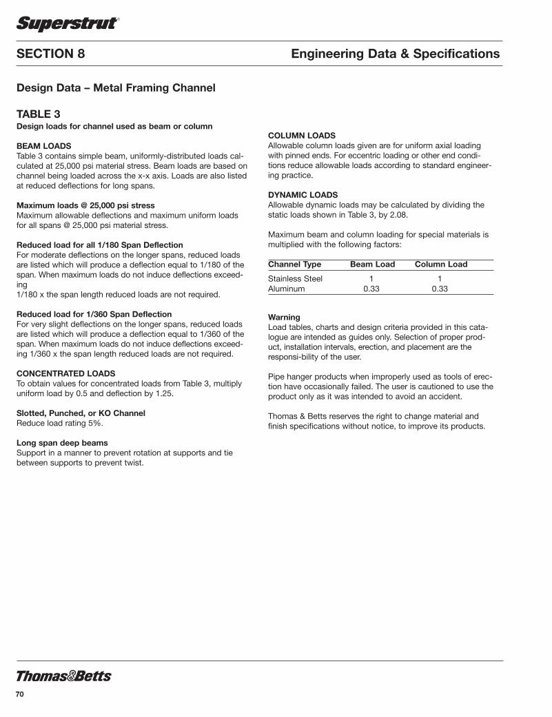
Design Data – Metal Framing Channel
TABLE 3Design loads for channel used as beam or column
BEAM LOADSTable 3 contains simple beam, uniformly-distributed loads cal-culated at 25,000 psi material stress. Beam loads are based onchannel being loaded across the x-x axis. Loads are also listedat re duced deflections for long spans.
Maximum loads @ 25,000 psi stressMaximum allowable deflections and maximum uniform loadsfor all spans @ 25,000 psi material stress.
Reduced load for all 1/180 Span DeflectionFor moderate deflections on the longer spans, reduced loadsare listed which will produce a de flec tion equal to 1/180 of thespan. When maximum loads do not induce deflections ex ceed -ing1/180 x the span length reduced loads are not required.
Reduced load for 1/360 Span DeflectionFor very slight deflections on the longer spans, reduced loadsare listed which will produce a de flec tion equal to 1/360 of thespan. When maximum loads do not induce deflections ex ceed -ing 1/360 x the span length reduced loads are not required.
CONCENTRATED LOADSTo obtain values for concentrated loads from Table 3, multiply uniform load by 0.5 and deflection by 1.25.
Slotted, Punched, or KO ChannelReduce load rating 5%.
Long span deep beamsSupport in a manner to prevent rotation at supports and tiebetween supports to prevent twist.
COLUMN LOADSAllowable column loads given are for uniform axial loadingwith pinned ends. For eccentric loading or other end condi-tions reduce allowable loads according to standard engineer-ing practice.
DYNAMIC LOADSAllowable dynamic loads may be calculated by dividing the static loads shown in Table 3, by 2.08.
Maximum beam and column loading for special materials ismultiplied with the following factors:
Channel Type Beam Load Column Load
Stainless Steel 1 1Aluminum 0.33 0.33
WarningLoad tables, charts and design criteria provided in this cata-logue are intended as guides only. Selection of proper prod-uct, installation intervals, erection, and placement are theresponsi-bility of the user.
Pipe hanger products when improperly used as tools of erec-tion have occasionally failed. The user is cautioned to use theproduct only as it was intended to avoid an accident.
Thomas & Betts reserves the right to change material andfinish specifications without notice, to improve its products.
SECTION 8 Engineering Data & Specifications
70
SSTRUT-E4.pdf 70 1/31/2012 10:30:10 AM

71
Engineering Data & Specifications SECTION 8
Design Data – Metal Framing ChannelTABLE 3 (cont’d.)
When no numbers are shown, use the maximum uniform load.Deflections are given in inches; loads in lb
SINGLE CHANNEL Maximum 1/180 1/360 Uniform Span Span Col.
Cat. No. Depth Ga. Load Defl. Load Defl. Load Defl. Load
12” BEAM OR COLUMN
A1200 1-5/8 12 3,534 .014 .067 .033 10,533B1200 13/16 12 1,050 .026 .067 .033 6,683C1200 1-3/8 12 2,584 .016 .067 .033 9,345D1200 1 12 1,538 .022 .067 .033 8,670E1200 2-7/16 12 6,650 .010 .067 .033 13,830
H1200 3-1/4 12 10,583 .008 .067 .033 17,106
A1400 1-5/8 14 2,434 .015 .067 .033 7,575B1400 13/16 14 850 .028 .067 .033 4,950
18” BEAM OR COLUMN
A1200 1-5/8 12 2,355 .033 .100 .050 10,2100B1200 13/16 12 700 .059 .100 .050 6,058C1200 1-3/8 12 1,723 .038 .100 .050 8,970D1200 1 12 1,025 .052 .100 .050 7,930E1200 2-7/16 12 4,434 .023 .100 .050 13,482H1200 3-1/4 12 7,055 .016 .100 .050 16,693
A1400 1-5/8 14 1,623 .031 .100 .050 7,334B1400 13/16 14 566 .063 .100 453 .050 4,150
24” BEAM OR COLUMN
A1200 1-5/8 12 1,766 .058 .133 .067 9,842B1200 13/16 12 525 .105 .133 333 .067 5,315C1200 1-3/8 12 1,291 .066 .133 .067 8,545D1200 1 12 769 .087 .133 490 .067 7,050E1200 2-7/16 12 3,325 .039 .133 .067 13,082H1200 3-1/4 12 5,291 .030 .133 .067 16,277
A1400 1-5/8 14 1,216 .056 .133 .067 7,058B1400 13/16 14 425 .110 .133 258 .067 4,000
30” BEAM OR COLUMN
A1200 1-5/8 12 1,414 .089 .167 .083 9,419B1200 13/16 12 420 .164 .167 266 .083 4,465C1200 1-3/8 12 1,034 .104 .167 1,040 .083 8,060D1200 1 12 .615 .129 .167 389 .083 6,650E1200 2-7/16 12 2,660 .063 .167 .083 12,640H1200 3-1/4 12 4,234 .046 .167 .083 15,698
A1400 1-5/8 14 974 .088 .167 .083 6,753B1400 13/16 14 340 .172 .167 165 .083 3,420
DOUBLE CHANNEL (Single Channels welded back-to-back) Maximum 1/180 1/360 Uniform Span Span Col.
Cat. No. Depth Ga. Load Defl. Load Defl. Load Defl. Load
A1202 3-1/4 12 .008 .067 .033 21,177B1202 1-5/8 12 3,016 .016 .067 .033 14,110C1202 2-3/4 12 .010 .067 .033 18,990D1202 2 12 .012 .067 .033 18,312E1202 4-7/8 12 .005 .067 .033 27,623
H1202 6-1/2 12 .004 .067 .033 34,210
A1402 3-1/4 14 .008 .067 .033 15,250B1402 1-5/8 14 2,300 .016 .067 .033 10,390
A1202 3-1/4 12 .018 .100 .050 20,609B1202 1-5/8 12 2,011 .036 .100 .050 13,440C1202 2-3/4 12 4,811 .021 .100 .050 18,470D1202 2 12 .028 .100 .050 17,942E1202 4-7/8 12 .013 .100 .050 16,926H1202 6-1/2 12 .009 .100 .050 33,390
A1402 3-1/4 14 .018 .100 .050 14,867B1402 1-5/8 14 1,534 .036 .100 .050 9,910
A1202 3-1/4 12 4,858 .031 .133 .067 19,974B1202 1-5/8 12 1,509 .064 .133 .067 12,670C1202 2-3/4 12 3,609 .038 .133 .067 17,890D1202 2 12 2,680 .042 .133 .067 17,160E1202 4-7/8 12 .021 .133 .067 26,143H1202 6-1/2 12 .016 .133 .067 32,435
A1402 3-1/4 14 3,425 .033 .133 .067 14,426B1402 1-5/8 14 1,150 .064 .133 .067 9,350
A1202 3-1/4 12 3,886 .049 .167 .083 19,261B1202 1-5/8 12 1,206 .100 .167 .083 11,803C1202 2-3/4 12 2,886 .059 .167 .083 17,230D1202 2 12 2,128 .084 .167 .083 16,480E1202 4-7/8 12 7,806 .034 .167 .083 25,259H1202 6-1/2 12 .025 .167 .083 31,395
A1402 3-1/4 14 2,740 .050 .167 .083 13,937B1402 1-5/8 14 920 .100 .167 .083 8,730
SSTRUT-E4.pdf 71 1/31/2012 10:30:10 AM

SECTION 8 Engineering Data & Specifications
Design Data – Metal Framing ChannelTABLE 3 (cont’d.)
When no numbers are shown, use the maximum uniform load.Deflections are given in inches; loads in lb
DOUBLE CHANNEL (Single Channels welded back-to-back) Maximum 1/180 1/360 Uniform Span Span Col.
Cat. No. Depth Ga. Load Defl. Load Defl. Load Defl. Load
A1202 3-1/4 12 3,239 .071 .200 .100 18,470B1202 1-5/8 12 1,005 .144 .200 702 .100 10,840C1202 2-3/4 12 2,400 .085 .200 .100 16,500D1202 2 12 1,428 .114 .200 1248 .100 15,057E1202 4-7/8 12 6,505 .048 .200 .100 24,316H1202 6-1/2 12 .036 .200 .100 30,265
A1402 3-1/4 14 2,284 .071 .200 .100 13,416B1402 1-5/8 14 766 .144 .200 535 .100 8,050
A1202 3-1/4 12 2,776 .098 .233 .117 17,635B1202 1-5/8 12 863 .195 .233 516 .117 9,790C1202 2-3/4 12 2,063 .115 .233 .117 15,730D1202 2 12 1,224 .166 .233 1069 .117 13,042E1202 4-7/8 12 5,576 .065 .233 .117 23,272H1202 6-1/2 12 .049 .233 .117 29,025
A1402 3-1/4 14 1,958 .225 .233 .117 12,832B1402 1-5/8 14 658 .195 .233 393 .117 7,300
A1202 3-1/4 12 2,429 .128 .267 .133 16,730B1202 1-5/8 12 754 .255 .267 395 .133 8,640C1202 2-3/4 12 1,804 .151 .267 .133 14,890D1202 2 12 1,071 .203 .267 702 .133 11,387E1202 4-7/8 12 4,879 .085 .267 .133 22,170H1202 6-1/2 12 .064 .267 .133 27,700
A1402 3-1/4 14 1,713 .128 .267 .133 12,223B1402 1-5/8 14 575 .255 .267 301 .133 6,480
A1202 3-1/4 12 2,159 .161 .300 .150 15,763B1202 1-5/8 12 670 .323 .300 312 .150 7,405C1202 2-3/4 12 1,604 .190 .300 1,263 .150 13,990D1202 2 12 952 .266 .300 624 .150 10,391E1202 4-7/8 12 4,338 .108 .300 .150 20,980H1202 6-1/2 12 7,149 .081 .300 .150 16,280
A1402 3-1/4 14 1,523 .161 .300 .150 11,566B1402 1-5/8 14 511 .323 .300 238 .150 5,580
SINGLE CHANNEL Maximum 1/180 1/360 Uniform Span Span Col.
Cat. No. Depth Ga. Load Defl. Load Defl. Load Defl. Load
36” BEAM OR COLUMN
A1200 1-5/8 12 1,178 .129 .200 917 .100 8,962B1200 13/16 12 350 .236 .200 148 .100 3,498C1200 1-3/8 12 861 .149 .200 578 .100 7,525D1200 1 12 513 .198 .200 217 .100 4,335E1200 2-7/16 12 2,216 .088 .200 .100 12,160H1200 3-1/4 12 3,528 .068 .200 .100 15,132
A1400 1-5/8 14 811 .126 .200 640 .100 6,416B1400 13/16 14 284 .248 .200 115 .100 2,755
42” BEAM OR COLUMN
A1200 1-5/8 12 1,010 .175 .233 674 .117 8,466B1200 13/16 12 300 .323 217 .233 109 .117 2,579C1200 1-3/8 12 738 .203 .233 425 .117 6,945D1200 1 12 440 .264 319 .233 160 .117 3,280E1200 2-7/16 12 1,900 .120 .233 .117 11,698H1200 3-1/4 12 3,024 .091 .233 .117 14,514
A1400 1-5/8 14 695 .160 .233 470 .117 6,051B1400 13/16 14 243 .336 168 .233 84 .117 2,060
48” BEAM OR COLUMN
A1200 1-5/8 12 884 .228 .267 516 .133 7,943B1200 13/16 12 263 .420 167 .267 83 .133 1,981C1200 1-3/8 12 646 .265 .267 325 .133 6,325D1200 1 12 384 .352 244 .267 122 .133 2,439E1200 2-7/16 12 1,663 .156 .267 .133 11,092H1200 3-1/4 12 2,646 .120 .267 .133 13,850
A1400 1-5/8 14 609 .120 .267 360 .133 5,658B1400 13/16 14 213 .440 129 .267 64 .133 1,580
54” BEAM OR COLUMN
A1200 1-5/8 12 785 .289 .300 408 .150 7,369B1200 13/16 12 234 .533 132 .300 66 .150 1,555C1200 1-3/8 12 574 .335 .300 257 .150 5,650D1200 1 12 341 .466 193 .300 96 .150 2,012E1200 2-7/16 12 1,478 .198 .300 1,123 .150 10,505H1200 3-1/4 12 2,351 .151 .300 .150 13,150
A1400 1-5/8 14 541 .286 .300 284 .150 5,241B1400 13/16 14 189 .556 102 .300 51 .150 1,250
72
SSTRUT-E4.pdf 72 1/31/2012 10:30:10 AM

73
Engineering Data & Specifications SECTION 8
Design Data – Metal Framing ChannelTABLE 3 (cont’d.)
When no numbers are shown, use the maximum uniform load.Deflections are given in inches; loads in lb
SINGLE CHANNEL Maximum 1/180 1/360 Uniform Span Span Col.
Cat. No. Depth Ga. Load Defl. Load Defl. Load Defl. Load
60” BEAM OR COLUMN
A1200 1-5/8 12 706 .358 .333 330 .167 6,762B1200 13/16 12 210 .658 107 .333 53 .167 -C1200 1-3/8 12 516 .414 .333 208 .167 4,920D1200 1 12 308 .550 157 .333 78 .167 1,561E1200 2-7/16 12 1,330 .244 .333 909 .167 9,874H1200 3-1/4 12 2,116 .186 .333 .167 12,406
A1400 1-5/8 14 486 .353 .333 231 .167 4,792B1400 13/16 14 170 .687 82 .333 41 .167 -
66” BEAM OR COLUMN
A1200 1-5/8 12 643 .432 .367 273 .183 6,127B1200 13/16 12 191 .795 88 .367 44 .183 -C1200 1-3/8 12 470 .501 344 .367 172 .183 4,145D1200 1 12 280 .675 129 .367 65 .183 1,280E1200 2-7/16 12 1,210 .295 .367 753 .183 9,211H1200 3-1/4 12 1,924 .226 .367 .183 11,616
A1400 1-5/8 14 443 .426 .367 190 .183 4,311B1400 13/16 14 155 .831 68 .367 35 .183 -
72” BEAM OR COLUMN
A1200 1-5/8 12 589 .514 459 .400 299 .200 5,436B1200 13/16 12 175 .946 74 .400 37 .200 -C1200 1-3/8 12 430 .595 289 .400 144 .200 3,485D1200 1 12 256 .792 108 .400 54 .200 1,084E1200 2-7/16 12 1,108 .351 .400 632 .200 8,509H1200 3-1/4 12 1,839 .269 .400 1,313 .200 10,782
A1400 1-5/8 14 405 .506 320 .400 160 .200 3,809B1400 13/16 14 141 .989 57 .400 29 200 -
84” BEAM OR COLUMN
A1200 1-5/8 12 505 .700 337 .467 168 .233 4,061B1200 13/16 12 54 .467 27 .233 -C1200 1-3/8 12 369 .811 212 .467 106 .233 2,565D1200 1 12 220 1.079 92 .467 58 .233 796E1200 2-7/16 12 950 .479 .467 464 .233 6,991H1200 3-1/4 12 1,513 .366 .467 965 .233 8,988
A1400 1-5/8 14 348 .691 235 .467 118 .233 2,827B1400 13/16 14 42 .467 21 .233 -
DOUBLE CHANNEL (Single Channels welded back-to-back) Maximum 1/180 1/360 Uniform Span Span Col.
Cat. No. Depth Ga. Load Defl. Load Defl. Load Defl. Load
A1202 3-1/4 12 1,944 .199 .333 .167 14,738B1202 1-5/8 12 604 .398 .333 253 .167 6,100C1202 2-3/4 12 1,444 .235 .333 1,023 .167 13,050D1202 2 12 257 .318 .333 449 .167 7,531E1202 4-7/8 12 3,904 .133 .333 .167 19,734H1202 6-1/2 12 6,434 .100 .333 .167 24,810
A1402 3-1/4 14 1,370 .199 .333 .167 10,878B1402 1-5/8 14 460 .399 .333 193 .167 4,640
A1202 3-1/4 12 1,766 .240 .367 1,347 .183 13,646B1202 1-5/8 12 549 .481 418 .367 209 .183 5,055C1202 2-3/4 12 1,313 .285 .367 846 .183 12,030D1202 2 12 779 .377 593 .367 360 .183 6,581E1202 4-7/8 12 3,549 .180 .367 .183 18,415H1202 6-1/2 12 5,849 .120 .367 .183 23,230
A1402 3-1/4 14 1,245 .241 .367 949 .183 10,133B1402 1-5/8 14 419 .483 318 .367 159 .183 3,840
A1202 3-1/4 12 1,620 .286 .400 1,132 .200 12,500B1202 1-5/8 12 503 .574 351 .400 176 .200 4,230C1202 2-3/4 12 1,203 .339 .400 710 .200 10,980D1202 2 12 714 .457 468 .400 312 .200 5,230E1202 4-7/8 12 3,253 .191 .400 .200 17,023H1202 6-1/2 12 5,361 .143 .400 .200 21,560
A1402 3-1/4 14 1,141 .286 .400 798 .200 9,340B1402 1-5/8 14 384 .574 267 .400 134 .200 3,220
A1202 3-1/4 12 1,388 .390 .467 832 .233 9,992B1202 1-5/8 12 431 .780 258 .467 129 .233 3100C1202 2-3/4 12 1,031 .461 .467 522 .233 8,670D1202 2 12 612 .623 344 .467 229 .233 3,842E1202 4-7/8 12 2,788 .260 .467 .233 13,993H1202 6-1/2 12 4,595 .195 .467 .233 17,975
A1402 3-1/4 14 979 .390 .467 586 .233 7,682B1402 1-5/8 14 329 .781 197 .467 98 .233 2,370
SSTRUT-E4.pdf 73 1/31/2012 10:30:10 AM
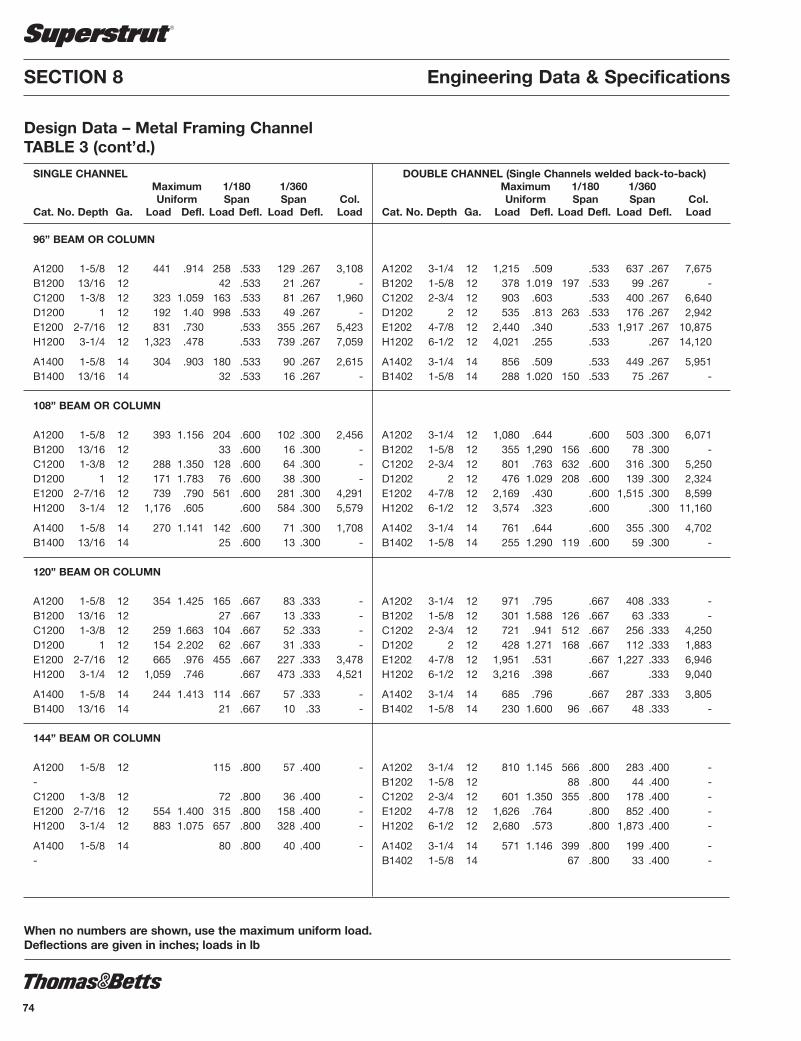
SECTION 8 Engineering Data & Specifications
Design Data – Metal Framing ChannelTABLE 3 (cont’d.)
When no numbers are shown, use the maximum uniform load.Deflections are given in inches; loads in lb
SINGLE CHANNEL Maximum 1/180 1/360 Uniform Span Span Col.
Cat. No. Depth Ga. Load Defl. Load Defl. Load Defl. Load
96” BEAM OR COLUMN
A1200 1-5/8 12 441 .914 258 .533 129 .267 3,108B1200 13/16 12 42 .533 21 .267 -C1200 1-3/8 12 323 1.059 163 .533 81 .267 1,960D1200 1 12 192 1.40 998 .533 49 .267 -E1200 2-7/16 12 831 .730 .533 355 .267 5,423H1200 3-1/4 12 1,323 .478 .533 739 .267 7,059
A1400 1-5/8 14 304 .903 180 .533 90 .267 2,615B1400 13/16 14 32 .533 16 .267 -
108” BEAM OR COLUMN
A1200 1-5/8 12 393 1.156 204 .600 102 .300 2,456B1200 13/16 12 33 .600 16 .300 -C1200 1-3/8 12 288 1.350 128 .600 64 .300 -D1200 1 12 171 1.783 76 .600 38 .300 -E1200 2-7/16 12 739 .790 561 .600 281 .300 4,291H1200 3-1/4 12 1,176 .605 .600 584 .300 5,579
A1400 1-5/8 14 270 1.141 142 .600 71 .300 1,708B1400 13/16 14 25 .600 13 .300 -
120” BEAM OR COLUMN
A1200 1-5/8 12 354 1.425 165 .667 83 .333 -B1200 13/16 12 27 .667 13 .333 -C1200 1-3/8 12 259 1.663 104 .667 52 .333 -D1200 1 12 154 2.202 62 .667 31 .333 -E1200 2-7/16 12 665 .976 455 .667 227 .333 3,478H1200 3-1/4 12 1,059 .746 .667 473 .333 4,521
A1400 1-5/8 14 244 1.413 114 .667 57 .333 -B1400 13/16 14 21 .667 10 .33 -
144” BEAM OR COLUMN
A1200 1-5/8 12 115 .800 57 .400 -- C1200 1-3/8 12 72 .800 36 .400 -E1200 2-7/16 12 554 1.400 315 .800 158 .400 -H1200 3-1/4 12 883 1.075 657 .800 328 .400 -
A1400 1-5/8 14 80 .800 40 .400 --
DOUBLE CHANNEL (Single Channels welded back-to-back) Maximum 1/180 1/360 Uniform Span Span Col.
Cat. No. Depth Ga. Load Defl. Load Defl. Load Defl. Load
A1202 3-1/4 12 1,215 .509 .533 637 .267 7,675B1202 1-5/8 12 378 1.019 197 .533 99 .267 -C1202 2-3/4 12 903 .603 .533 400 .267 6,640D1202 2 12 535 .813 263 .533 176 .267 2,942E1202 4-7/8 12 2,440 .340 .533 1,917 .267 10,875H1202 6-1/2 12 4,021 .255 .533 .267 14,120
A1402 3-1/4 14 856 .509 .533 449 .267 5,951B1402 1-5/8 14 288 1.020 150 .533 75 .267 -
A1202 3-1/4 12 1,080 .644 .600 503 .300 6,071B1202 1-5/8 12 355 1,290 156 .600 78 .300 -C1202 2-3/4 12 801 .763 632 .600 316 .300 5,250D1202 2 12 476 1.029 208 .600 139 .300 2,324E1202 4-7/8 12 2,169 .430 .600 1,515 .300 8,599H1202 6-1/2 12 3,574 .323 .600 .300 11,160
A1402 3-1/4 14 761 .644 .600 355 .300 4,702B1402 1-5/8 14 255 1.290 119 .600 59 .300 -
A1202 3-1/4 12 971 .795 .667 408 .333 -B1202 1-5/8 12 301 1.588 126 .667 63 .333 -C1202 2-3/4 12 721 .941 512 .667 256 .333 4,250D1202 2 12 428 1.271 168 .667 112 .333 1,883E1202 4-7/8 12 1,951 .531 .667 1,227 .333 6,946H1202 6-1/2 12 3,216 .398 .667 .333 9,040
A1402 3-1/4 14 685 .796 .667 287 .333 3,805B1402 1-5/8 14 230 1.600 96 .667 48 .333 -
A1202 3-1/4 12 810 1.145 566 .800 283 .400 -B1202 1-5/8 12 88 .800 44 .400 -C1202 2-3/4 12 601 1.350 355 .800 178 .400 -E1202 4-7/8 12 1,626 .764 .800 852 .400 -H1202 6-1/2 12 2,680 .573 .800 1,873 .400 -
A1402 3-1/4 14 571 1.146 399 .800 199 .400 -B1402 1-5/8 14 67 .800 33 .400 -
74
SSTRUT-E4.pdf 74 1/31/2012 10:30:11 AM

75
Engineering Data & Specifications SECTION 8
Design Data – Metal Framing ChannelTABLE 3 (cont’d.)
When no numbers are shown, use the maximum uniform load.Deflections are given in inches; loads in lb
DOUBLE CHANNEL (Single Channels welded back-to-back) Maximum 1/180 1/360 Uniform Span Span Col.
Cat. No. Depth Ga. Load Defl. Load Defl. Load Defl. Load
A1202 3-1/4 12 694 1.563 916 .933 208 .467 -B1202 1-5/8 12 64 .933 32 .467 -C1202 2-3/4 12 515 1.850 261 .933 130 .467 -E1202 4-7/8 12 1,394 1.0401,255 .933 626 .467 -H1202 6-1/2 12 2,298 .780 .933 1,326 .467 -
A1402 3-1/4 14 489 1.563 293 .933 147 .467 -B1402 1-5/8 14 49 .933 25 .467 -
A1202 3-1/4 12 318 1.07 159 .533 --C1202 2-3/4 12 200 1.07 100 .533 -E1202 4-7/8 12 1,220 1.363 958 1.07 479 .533 -H1202 6-1/2 12 2,010 1.019 1.07 1,053 .533 -
A1402 3-1/4 14 224 1.07 112 .533 --
A1202 3-1/4 12 252 1.20 126 .600 --C1202 2-3/4 12 158 1.20 79 .600 -E1202 4-7/8 12 1,084 1.725 757 1.20 379 .600 -H1202 6-1/2 12 1,788 1.288 1.20 832 .600 -
A1402 3-1/4 14 177 1.20 89 .600 --
A1202 3-1/4 12 204 1.33 102 .667 --C1202 2-3/4 12 128 1.33 64 .667 -E1202 4-7/8 12 613 1.33 307 .667 -H1202 6-1/2 12 1,609 1.588 1.33 674 .667 -
A1402 3-1/4 14 144 1.33 72 .667 --
SINGLE CHANNEL Maximum 1/180 1/360 Uniform Span Span Col.
Cat. No. Depth Ga. Load Defl. Load Defl. Load Defl. Load
168” BEAM OR COLUMN
A1200 1-5/8 12 84 .933 42 .467 -- C1200 1-3/8 12 53 .933 27 .467 -E1200 2-7/16 12 475 1.912 233 .933 116 .467 -H1200 3-1/4 12 756 1.463 482 .933 241 .467 -
A1400 1-5/8 14 60 .933 30 .467 --
192” BEAM OR COLUMN
---E1200 2-7/16 12 178 1.07 89 .533 -H1200 3-1/4 12 661 1.91 369 1.07 185 .533 -
--
216” BEAM OR COLUMN
---E1200 2-7/16 12 140 1.20 70 .600 -H1200 3-1/4 12 292 1.20 146 .600 -
--
240” BEAM OR COLUMN
---E1200 2-7/16 12 114 .334 57 .667 -H1200 3-1/4 12 236 .334 118 .667 -
--
SSTRUT-E4.pdf 75 1/31/2012 10:30:11 AM

700 lb 700 lb
AB201 AB203
Flat Plate Fittings
Both ends supported
AB206 A1200 1000 lb A1400 800 lb
SECTION 8 Engineering Data & Specifications
Design Data – Metal Framing ChannelTABLE 4Safe bearing loads for 1-5/8” channel and combinations.Safety factor of 2-1/2
Recommended Section Load in lb
A1200 5000 A1400 3500
B1200 6000 B1400 3400
C1200 5000 E1200 5000 H1200 4000
Recommended Section Load in lb
A1200 3500 A1400 2500
B1200 4000 B1400 2600
C1200 3500 E1200 3500 H1200 2000
RecommendedSection Load in lb
A1200 8000A1400 5500
B1200 9000B1400 4800
C1200 8000E1200 8000H1200 5500
Both ends supported
AB202 A1200 1500 lb A1400 1000 lb
Both ends supported
AB205 A1200 2000 lbAB216 A1400 2000 lb
Both ends supported
AB202 A1200 1000 lb A1400 650 lb
Both ends supported
AB203 A1200 2000 lb A1400 1500 lb
Both ends supported
AB213 A1200 3000 lbAB214 A1400 2000 lb
Both ends supported
AB204 A1200 1500 lbAB215 A1400 1000 lb
AB20 1500 lb
TABLE 5Design load table for typical channel connections.Safety factor of 2-1/2 based on ultimate strength of the connection. Loaddiagrams indicate up to three design loads, for 12 gauge and 14 gauge channel applications.
90° Fittings (When used in position shown)
76
SSTRUT-E4.pdf 76 1/31/2012 10:30:11 AM

77
Engineering Data & Specifications SECTION 8
Design ApplicationsCANTILEVER BEAMS
BEAMS FIXED AT BOTH ENDS
BEAMS FIXED ON ONE END, SUPPORTED AT OTHER
SIMPLE BEAMS
SSTRUT-E4.pdf 77 1/31/2012 10:30:11 AM

SECTION 8 Engineering Data & Specifications
Design ApplicationsTABLE 6Conversion Factors for Beams with Various Static Loading Conditions
Load tables on pages 104 through 108 for A, B, C, E, and Hseries channel are for single span beams supported at the ends.These can be used in the majority of cases. There are timeswhen it is necessary to know what happens with other loading
and support conditions. Some common arrangements areshown in Table 6. Simply multiply the loads from the DesignLoad Tables times the factors given in Table 6. Examplesshown on page 112.
LOAD DEFLECTION LOAD AND SUPPORT CONDITION FACTOR FACTOR
1. Simple Beam - Uniform Load 1.00 1.00
2. Simple Beam - Concentrated Load at Center .50 1.25
3. Simple Beam - Two Equal Concentrated Loads at 1/4 Points 1.00 1.10
4. Beam Fixed at Both Ends - Uniform Load 1.50 .30
5. Beam Fixed at Both Ends - Concentrated Load at Center 1.00 .40
6. Cantilever Beam - Uniform Load .25 2.40
7. Cantilever Beam - Concentrated Load at End .12 3.20
8. Continuous Beam - Two Equal Spans - Uniform Load on One Span 1.30 .92
9. Continuous Beam - Two Equal Spans - Uniform Load on Both Ends 1.00 .42
10. Continuous Beam - Two Equal Spans - Concentrated Load at Center of One Span .62 .71
11. Continuous Beam - Two Equal Spans - Concentrated Load at Center of Both Spans .67 .48
78
SSTRUT-E4.pdf 78 1/31/2012 10:30:11 AM

79
ILLUSTRATION I
COLUMNHEIGHT
K value .65 .80 1.0 1.2
Engineering Data & Specifications SECTION 8
Design ApplicationsEXAMPLE IPROBLEM:Determine the load and deflectionof an A1200 beam continuousover one support and loadeduniformly on one span.
SOLUTION:A. From load table 3 for A1200 the load for a 5’0” span is 706
lb and deflection is .358”.B. Multiply by factors from Table 6. Load = 706 lb x 1.30 = 917.8 lb Deflection = .358 x .92 = .329”
EXAMPLE IIPROBLEM:Determine load and deflectionof an E1200 cantilever beamwith a concentrated load onthe end.
SOLUTION:A. From load table 3 for E1200 the load for a 3’0” span is 2216
lb and deflection is .088”.
B. Multiply by factors from Table 6. Load = 2216 lb x .12 = 265.9 lb Deflection - .088 x 3.20 = .282”
If other end conditions are used, axial loading should be cal -cu lat ed using procedures in the AISI specification for thedesign of cold formed steel structural members (SG671) andthe en gi neer ing values for Superstrut® channel given in Table1.
END CONDITION CODE
Rotation fixed and translation fixed
Rotation free and translation fixed
Rotation fixed and translation free
COLUMN LOADINGThe load bearing capacity of column or compression membersis a function of the inherent configurational strength, theunbraced length and design of the end connections.
Values of axial column loading given in Table 3 were calculatedusing a rotationally free and translation fixed correction at eachend (see illustration I). This gives an end condition constant (K) of 1.
TABLE 7Load Carrying Capacities of Hot Rolled Steel Rod
Design Load lb for Serv. Tem per a ture Nominal Root Area 343°C 399°C Rod Dia. Thread (650°F) (750°F)
3/8 .068 610 540 1/2 .126 1130 1010 5/8 .202 1810 1610 3/4 .302 2710 2420 7/8 .419 3770 3360
Dimensions are in inches.Safety factor of 5.
TABLE 8Rod Size Determined by Pipe Size for Fire Protection
Pipe Rod Size Size
3/4 to 2 3/8 2-1/2 to 3-1/2 1/2
4 to 5 5/8 6 3/4 8 to 12 7/8
Dimensions are in inches.
SSTRUT-E4.pdf 79 1/31/2012 10:30:11 AM

SECTION 8 Engineering Data & Specifications
Design ApplicationsTABLE 9Maximum Spacing between Pipe Supports
Steel Pipe
Nom. Pipe Size 1/2 3/4 1 1-1/2 2 2-1/2 3 3-1/2 4 5 6 8 10 12 14 16 18 20 24 (inches)
Max. Spacing 5 6 7 9 10 11 12 13 14 16 17 19 22 23 25 27 28 30 32 (feet)
Copper Pipe
Nom. Pipe Size 1/2 3/4 1 1-1/4 1-1/2 2 2-1/2 3 3-1/2 4 (inches)
Max. Spacing 5 6 6 7 8 9 10 10 11 12 (feet)
TABLE 10Minimum Spacing (inches) between Centers of Standard Pipe When Using Superstrut #702 Pipe Straps
Nom. Pipe 1/2 3/4 1 1-1/4 1-1/2 2 2-1/2 3 3-1/2 4 5 6 8Size (inches)
1/2 1-3/16 3/4 1-5/16 1-7/16 1 1-1/2 1-5/8 1-3/4
1-1/4 1-3/4 1-7/8 2 2-1/4 1-1/2 1-15/16 2-1/16 2-3/16 2-7/16 2-9/16 2 2-3/16 2-5/16 2-1/2 2-3/4 2-7/8 3-1/8
2-1/2 2-7/16 2-9/16 2-3/4 3 3-1/8 3-3/8 3-5/8 3 2-13/16 2-15/16 3-1/16 3-5/16 3-7/16 3-3/4 4 4-5/16 3-1/2 3-1/8 3-1/4 3-3/8 3-5/8 3-3/4 4-1/16 4-5/16 4-5/8 4-15/16
4 3-7/16 3-9/16 3-15/16 4-1/16 4-3/8 4-5/8 4-15/16 5-1/4 5-9/16 6 4-3/4 4-7/8 5 5-1/4 5-3/8 5-5/8 5-7/8 6-3/16 6-1/2 6-13/16 7-7/16 8-1/8 8 5-7/16 6 6-1/8 6-3/8 6-1/2 6-3/4 7 7-5/16 7-5/8 8 8-9/16 9-1/4 10-3/8
80
SSTRUT-E4.pdf 80 1/31/2012 10:30:11 AM

81
Engineering Data & Specifications SECTION 8
Design ApplicationsTABLE 11Standard Dimensions and Weights of Piping Materials and Conduit
Mechanical (ANSI & API Standard, Schedule 40)
Nominal Std. Pipe Pipe Coupling Weight of Pipe Size O.D. O.D. Weights of Pipe Filled w/Water
(inches) (inches) (inches) lb/ft lb/ft
1/2 .84 1.06 .85 .98 3/4 1.05 1.31 1.13 1.36 1 1.32 1.58 1.68 2.05 1 - 1/4 1.66 1.90 2.27 2.92 1 - 1/2 1.90 2.20 2.72 3.60 2 2.38 2.75 3.65 5.11 2 - 1/2 2.88 3.25 5.79 7.87 3 3.50 4.00 7.58 10.78 3 - 1/2 4.00 4.63 9.11 13.39 4 4.50 5.00 10.79 16.30 5 5.56 6.30 14.62 23.28 6 6.63 7.39 18.97 31.48 8 8.63 9.23 28.56 50.24 10 10.75 41.00 74.00 12 12.75 50.00 99.00 14 14.00 64.00 122.00 16 16.00 63.00 142.00 18 18.00 71.00 172.00 20 20.00 79.00 205.00 22 22.00 87.00 240.00 24 24.00 95.00 277.00 26 26.00 103.00 322.00 28 28.00 111.00 364.00 30 30.00 119.00 410.00
Electrical Conduit
Rigid Steel Thin Wall (EMT)
Weight of Conduit Nominal Conduit w/Non-lead Conduit Conduit O.D. Weight of Conduit Covered Conductor O.D. Weight of Conduit Size (inches) lb/ft lb/ft (inches) lb/ft
1/2 .84 .85 1.04 .71 .29 3/4 1.05 1.13 1.40 .92 .44
1 1.32 1.68 2.35 1.16 .64
1 - 1/4 1.66 2.28 3.58 1.51 .95 2 2.38 3.68 7.21 2.20 1.40 2 - 1/2 2.88 5.82 10.22 2.88 2.30
3 3.50 7.62 14.51 3.50 2.70 4 4.50 10.89 21.48 4.50 4.00
Includes weight of heaviest conductor combination.
SSTRUT-E4.pdf 81 1/31/2012 10:30:11 AM

SECTION 8 Engineering Data & Specifications
Design ApplicationsTABLE 12Extra Strong Pipe (ANSI & API Standard, Schedule 80) A.S.A. B36.10 SCHEDULE Nominal Weight Water Weight Weight of Pipe NOS. AND NOMINAL Pipe Wall of per ft Filled WALL THICKNESS Size O.D. Thickness I.D. Pipe of Pipe w/Water DESIGNATIONS (inches) (inches) (inches) (inches) lb/ft lb lbs/ft
3/8 .675 .126 .423 .74 .061 .801 1/2 .840 .147 .546 1.09 .101 1.191 3/4 1.050 .154 .742 1.47 .188 1.668 1 1.315 .179 .957 2.17 .311 2.481 1-1/4 1.660 .191 1.278 3.00 .555 3.555
EXTRA STRONG 1-1/2 1.900 .200 1.500 3.63 .765 4.395 PIPE and 2 2.375 .218 1.939 5.03 1.279 6.309 SCHEDULE 80 PIPE 2-1/2 2.875 .276 2.323 7.66 1.834 9.497 (through 8”) 3 3.500 .300 2.900 10.30 2.860 13.160
3-1/2 4.000 .318 3.364 12.55 3.850 16.350
4 4.500 .337 3.826 15.00 4.980 19.980 5 5.563 .375 4.813 20.80 7.890 28.690 6 6.625 .432 5.761 28.60 11.290 39.890 8 8.625 .500 7.625 43.40 19.790 63.200
10 10.750 .500 9.750 54.70 32.300 87.000 12 12.750 .500 11.750 65.40 47.000 112.400 14 OD 14.000 .500 13.000 72.10 57.500 129.600 EXTRA STRONG PIPE 16 OD 16.000 .500 15.000 82.80 76.500 159.300 (10” through 24” OD) 18 OD 18.000 .500 17.000 93.50 98.400 191.900 20 OD 20.000 .500 19.000 104.10 122.800 226.900 24 OD 24.000 .500 23.000 125.50 180.100 305.600
10 10.750 .593 9.564 64.300 31.100 95.400 12 12.750 .687 11.376 88.50 44.000 132.500 14 OD 14.000 .750 12.500 106.10 53.200 159.300 SCHEDULE 80 PIPE 16 OD 16.000 .842 14.314 136.50 69.700 206.200 (10” through 24” OD) 18 OD 18.000 .937 16.126 170.80 88.500 259.300 20 OD 20.000 1.031 17.938 208.90 109.400 318.300 24 OD 24.000 1.218 21.564 296.40 158.300 454.700
TABLE 13Pipe Covering Weights (Thickness intended as guide, only)Thickness and weight of calcium silicate covering. Nominal 260° 360° 440° 525° 600° 700° 800° Pipe Thick. Thick. Thick. Thick. Thick. Thick. Thick. Size (inches) lb/ft (inches) lb/ft (inches) lb/ft (inches) lb/ft (inch es) lb/ft (inches) lb/ft (inch es) lb/ft
1 1 .68 1 .68 1 .68 1 .68 1-1/2 1.19 1-1/2 1.19 1-1/2 1.19 1-1/4 1 .75 1 .75 1 .75 1 .75 1-1/2 1.27 1-1/2 1.27 2 1.82 1-1/2 1 .88 1 .88 1 .88 1 .88 1-1/2 1.45 1-1/2 1.45 2 1.87
2 1 1.01 1 1.01 1 1.01 1-1/2 1.53 1-1/2 1.53 2 2.50 2 2.50 2-1/2 1 1.15 1 1.15 1 1.15 1-1/2 1.69 1-1/2 1.69 2 2.50 2-1/2 3.22 3 1 1.28 1 1.28 1 1.28 1-1/2 2.09 1-1/2 2.09 2 2.98 2-1/2 3.98
3-1/2 1 1.44 1 1.44 1-1/2 2.29 1-1/2 2.29 2 3.00 2 3.12 2-1/2 4.30 4 1 1.60 1 1.60 1-1/2 2.49 1-1/2 2.49 2 3.49 2 3.49 2-1/2 4.62 5 1 1.84 1 1.84 1-1/2 2.84 1-1/2 2.84 2 3.97 2 3.97 2-1/2 5.92
6 1-1/2 3.13 1-1/2 3.13 1-1/2 3.13 1-1/2 3.13 2 4.54 2 4.54 2-1/2 6.75 8 1-1/2 4.06 1-1/2 4.06 1-1/2 4.06 1-1/2 4.06 2 5.56 2 5.56 2-1/2 7.61
82
SSTRUT-E4.pdf 82 1/31/2012 10:30:11 AM
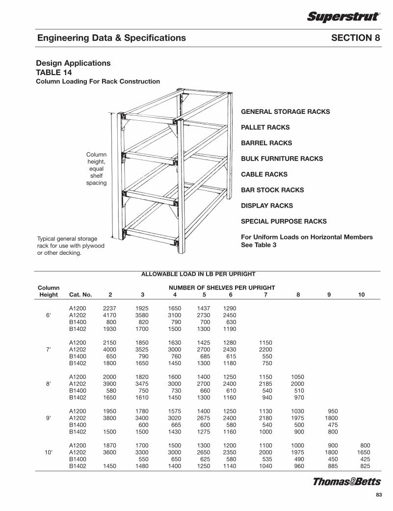
83
Engineering Data & Specifications SECTION 8
Design ApplicationsTABLE 14Column Loading For Rack Construction
ALLOWABLE LOAD IN LB PER UPRIGHT Column NUMBER OF SHELVES PER UPRIGHT Height Cat. No. 2 3 4 5 6 7 8 9 10
A1200 2237 1925 1650 1437 1290 6' A1202 4170 3580 3100 2730 2450 B1400 800 820 790 700 630 B1402 1930 1700 1500 1300 1190
A1200 2150 1850 1630 1425 1280 1150 7' A1202 4000 3525 3000 2700 2430 2200 B1400 650 790 760 685 615 550 B1402 1800 1650 1450 1300 1180 750
A1200 2000 1820 1600 1400 1250 1150 1050 8' A1202 3900 3475 3000 2700 2400 2185 2000 B1400 580 750 730 660 610 540 510 B1402 1650 1610 1450 1300 1160 940 970
A1200 1950 1780 1575 1400 1250 1130 1030 950 9' A1202 3800 3400 3020 2675 2400 2180 1975 1800 B1400 600 665 600 580 540 500 475 B1402 1500 1500 1430 1275 1160 1000 900 800
A1200 1870 1700 1500 1300 1200 1100 1000 900 800 10' A1202 3600 3300 3000 2650 2350 2000 1975 1800 1650 B1400 550 650 625 580 535 490 450 425 B1402 1450 1480 1400 1250 1140 1040 960 885 825
GENERAL STORAGE RACKS
PALLET RACKS
BARREL RACKS
BULK FURNITURE RACKS
CABLE RACKS
BAR STOCK RACKS
DISPLAY RACKS
SPECIAL PURPOSE RACKS
For Uniform Loads on Horizontal MembersSee Table 3
Typical general storagerack for use with plywoodor other decking.
Columnheight,equalshelf
spacing
SSTRUT-E4.pdf 83 1/31/2012 10:30:11 AM

B302 CONCRETE INSERT
E142-1/2 x 100 HEX.H.BOLTA100-1/2 SPRING NUT
AB201 90° ANGLE
AB22745° ANGLE
A1202CHANNEL
B1202CHANNEL
A1202CHANNEL
B100-1/2 SPRING NUT
SECTION 8 Engineering Data & Specifications
Design Applications — Mechanical Support
B302 CONCRETE INSERT
AB201 90° ANGLE
E142-1/2 x 100 HEX.H.BOLTB100-1/2 SPRING NUT
S256-12 BRACKETS203-14 BRACKET
S249-20 BRACKET
a= E142-1/2” x 100AA100-1/2 SPRING NUT
Suspended column, carrying brackets, braced to the ceiling.
E142-1/2 x 100 HEX.H.BOLTB100-1/2 SPRING NUT
AB239-2BRACE
A1202CHANNEL
Suspended column, holding bracket andconsole braced to wall.
Example 1 Example 2
Example 3 Example 4
Example 5 Example 6
AB241SQ. WASHER
A1200CHANNEL
U568SAFETYSTRAPU560
H.D. BEAM CLAMP
E145-1/2HEX. NUT
A1200CHANNEL
A1200CHANNEL
H104-1/2 x 10HANGER ROD
H104-1/2 x 10HANGER ROD
S202-21CROSS MEMBER
E145-1/2HEX. NUT
US562H.D. BEAM CLAMP
Trapeze with channels as cross membersusing beam clamps and hanger rods.
Sketch depicts the use of beam clamps on slanted beams.
60°
30°
Trapeze, constructedfrom channels, fittings.
The use of spot inserts is shown (SI400-1/2).Trapeze with S202 cross members using
hanger rods and concrete inserts.
AB201 90° ANGLE
E142-1/2 x 100 HEX.H.BOLT
B100-1/2 SPRING NUT
B1602CHANNEL
B1600CHANNEL
H104-1/2 x 10HANGER ROD
B302CONCRETEINSERT
C781-1/2SQUARE WASHER
E145-1/2HEX. NUT
A100-1/2SPRINGNUT
H119-1/2ROD COUPLING
H119-1/2ROD COUPLING
a
a
aa
SI400-1/2 SPOT INSERT
84
SSTRUT-E4.pdf 84 1/31/2012 10:30:11 AM
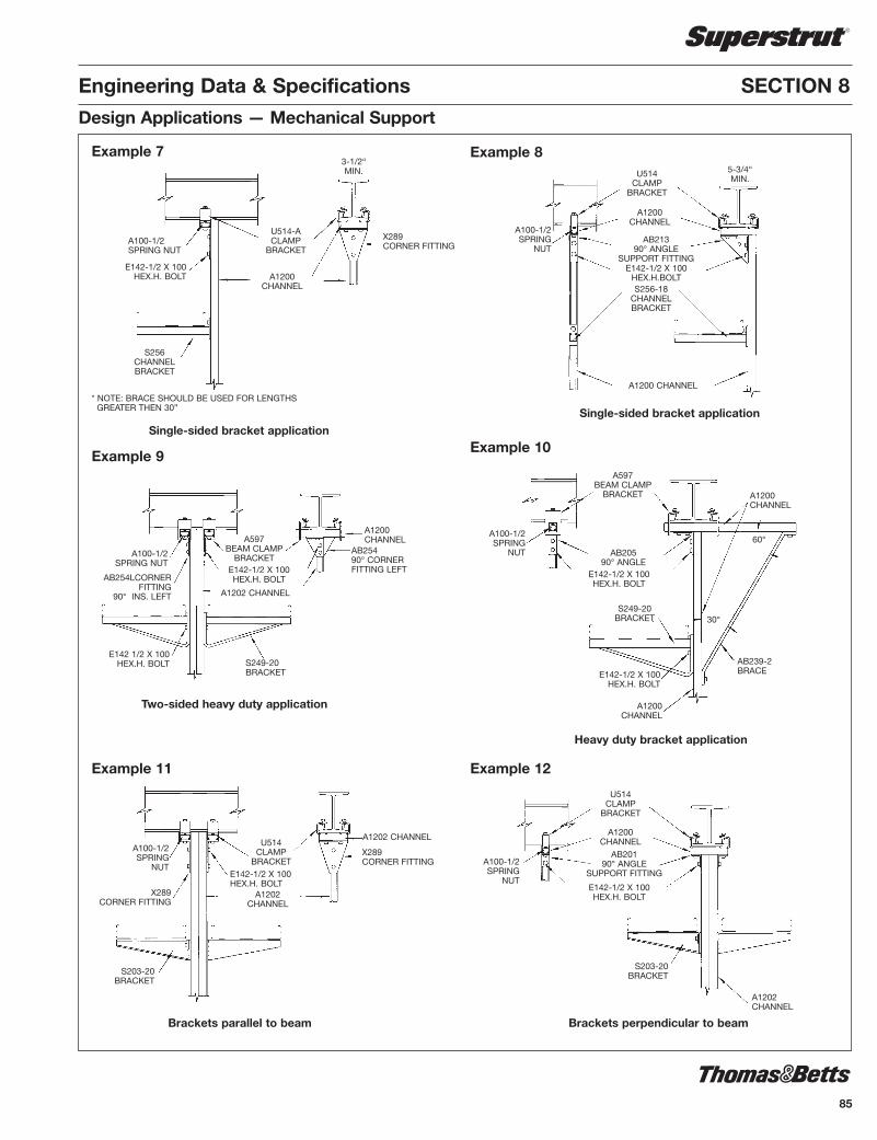
85
Engineering Data & Specifications SECTION 8
Example 7 Example 8
Example 9Example 10
Example 11 Example 12
Single-sided bracket application
3-1/2“MIN.
Single-sided bracket application
A100-1/2SPRING NUT
E142-1/2 X 100HEX.H. BOLT
S256CHANNELBRACKET
U514-ACLAMP
BRACKET
A1200CHANNEL
X289CORNER FITTING
* NOTE: BRACE SHOULD BE USED FOR LENGTHSGREATER THEN 30”
5-3/4“MIN.
U514CLAMP
BRACKET
A1200CHANNEL
AB21390° ANGLE
SUPPORT FITTINGE142-1/2 X 100
HEX.H.BOLTS256-18
CHANNELBRACKET
A100-1/2SPRING
NUT
A1200 CHANNEL
Two-sided heavy duty application
Heavy duty bracket application
A100-1/2SPRING NUT
AB254LCORNERFITTING
90° INS. LEFT
E142 1/2 X 100HEX.H. BOLT
A597BEAM CLAMP
BRACKETE142-1/2 X 100HEX.H. BOLT
A1202 CHANNEL
S249-20BRACKET
A1200 CHANNEL
AB25490° CORNERFITTING LEFT
A597BEAM CLAMP
BRACKET A1200 CHANNEL
A100-1/2SPRING
NUT AB20590° ANGLE
E142-1/2 X 100HEX.H. BOLT
S249-20BRACKET
E142-1/2 X 100HEX.H. BOLT
A1200CHANNEL
AB239-2BRACE
60°
30°
Brackets parallel to beam Brackets perpendicular to beam
A100-1/2SPRING
NUT
X289CORNER FITTING
S203-20BRACKET
U514CLAMP
BRACKETE142-1/2 X 100HEX.H. BOLT
A1202 CHANNEL
A1202 CHANNEL
X289CORNER FITTING A100-1/2
SPRINGNUT
U514CLAMP
BRACKET
A1200 CHANNEL
AB20190° ANGLE
SUPPORT FITTING
E142-1/2 X 100HEX.H. BOLT
S203-20BRACKET
A1202CHANNEL
Design Applications — Mechanical Support
SSTRUT-E4.pdf 85 1/31/2012 10:30:11 AM

ALPHANUMERIC INDEX
502 . . . . . . . . . . . . . . . . . . . . . . . . . . . .36507 . . . . . . . . . . . . . . . . . . . . . . . . . . . .36508 . . . . . . . . . . . . . . . . . . . . . . . . . . . .36509 . . . . . . . . . . . . . . . . . . . . . . . . . . . .36510 . . . . . . . . . . . . . . . . . . . . . . . . . . . .36511 . . . . . . . . . . . . . . . . . . . . . . . . . . . .36452TB . . . . . . . . . . . . . . . . . . . . . . . . . .11460-10TB . . . . . . . . . . . . . . . . . . . . . . .11500SC . . . . . . . . . . . . . . . . . . . . . . . . .36503SC . . . . . . . . . . . . . . . . . . . . . . . . .36512U . . . . . . . . . . . . . . . . . . . . . . . . . . .32540-1/2 . . . . . . . . . . . . . . . . . . . . . . . . .38540-3/4 . . . . . . . . . . . . . . . . . . . . . . . . .38540-3/8 . . . . . . . . . . . . . . . . . . . . . . . . .38540-5/8 . . . . . . . . . . . . . . . . . . . . . . . . .38542-1/2 . . . . . . . . . . . . . . . . . . . . . . . . .38542-3/8 . . . . . . . . . . . . . . . . . . . . . . . . .386H0 . . . . . . . . . . . . . . . . . . . . . . . . . . . .366H0 . . . . . . . . . . . . . . . . . . . . . . . . . . . .466H0-B . . . . . . . . . . . . . . . . . . . . . . . . . .466H0-T . . . . . . . . . . . . . . . . . . . . . . . . . .366H0-T . . . . . . . . . . . . . . . . . . . . . . . . . .466H0-TB . . . . . . . . . . . . . . . . . . . . . . . . .466H1 . . . . . . . . . . . . . . . . . . . . . . . . . . . .366H1 . . . . . . . . . . . . . . . . . . . . . . . . . . . .466H1-B . . . . . . . . . . . . . . . . . . . . . . . . . .466H1-T . . . . . . . . . . . . . . . . . . . . . . . . . .366H1-T . . . . . . . . . . . . . . . . . . . . . . . . . .466H1-TB . . . . . . . . . . . . . . . . . . . . . . . . .466H2 . . . . . . . . . . . . . . . . . . . . . . . . . . . .366H2 . . . . . . . . . . . . . . . . . . . . . . . . . . . .466H2 1/2 . . . . . . . . . . . . . . . . . . . . . . . .366H2-1/2 . . . . . . . . . . . . . . . . . . . . . . . .466H2-1/2-B . . . . . . . . . . . . . . . . . . . . . .466H2-B . . . . . . . . . . . . . . . . . . . . . . . . . .466H3-B . . . . . . . . . . . . . . . . . . . . . . . . . .466H3-SC . . . . . . . . . . . . . . . . . . . . . . . .366H3-SC . . . . . . . . . . . . . . . . . . . . . . . .466H3-TB . . . . . . . . . . . . . . . . . . . . . . . . .466H4 . . . . . . . . . . . . . . . . . . . . . . . . . . . .366H4 . . . . . . . . . . . . . . . . . . . . . . . . . . . .466H4-B . . . . . . . . . . . . . . . . . . . . . . . . . .466H4-TB . . . . . . . . . . . . . . . . . . . . . . . . .466H5 . . . . . . . . . . . . . . . . . . . . . . . . . . . .366H5 . . . . . . . . . . . . . . . . . . . . . . . . . . . .466H5-B . . . . . . . . . . . . . . . . . . . . . . . . . .466H5-TB . . . . . . . . . . . . . . . . . . . . . . . . .466H6 . . . . . . . . . . . . . . . . . . . . . . . . . . . .366H6 . . . . . . . . . . . . . . . . . . . . . . . . . . . .466H6-B . . . . . . . . . . . . . . . . . . . . . . . . . .466H7 . . . . . . . . . . . . . . . . . . . . . . . . . . . .366H7 . . . . . . . . . . . . . . . . . . . . . . . . . . . .466H7-B . . . . . . . . . . . . . . . . . . . . . . . . . .466H8 . . . . . . . . . . . . . . . . . . . . . . . . . . . .366H8 . . . . . . . . . . . . . . . . . . . . . . . . . . . .466H8-B . . . . . . . . . . . . . . . . . . . . . . . . . .466H9 . . . . . . . . . . . . . . . . . . . . . . . . . . . .366H9 . . . . . . . . . . . . . . . . . . . . . . . . . . . .466H9-B . . . . . . . . . . . . . . . . . . . . . . . . . .46701-045PG . . . . . . . . . . . . . . . . . . . . . .42701-055PG . . . . . . . . . . . . . . . . . . . . . .42701-065PG . . . . . . . . . . . . . . . . . . . . . .42701-075PG . . . . . . . . . . . . . . . . . . . . . .42701-088PG . . . . . . . . . . . . . . . . . . . . . .42701-100PG . . . . . . . . . . . . . . . . . . . . . .42701-113PG . . . . . . . . . . . . . . . . . . . . . .42701-126PG . . . . . . . . . . . . . . . . . . . . . .42701-140PG . . . . . . . . . . . . . . . . . . . . . .42701-153PG . . . . . . . . . . . . . . . . . . . . . .42701-167PG . . . . . . . . . . . . . . . . . . . . . .42701-180PG . . . . . . . . . . . . . . . . . . . . . .42701-193PG . . . . . . . . . . . . . . . . . . . . . .42701-204PG . . . . . . . . . . . . . . . . . . . . . .42701-225PG . . . . . . . . . . . . . . . . . . . . . .42701-237PG . . . . . . . . . . . . . . . . . . . . . .42701-245PG . . . . . . . . . . . . . . . . . . . . . .42701-257PG . . . . . . . . . . . . . . . . . . . . . .42701-287PG . . . . . . . . . . . . . . . . . . . . . .42701-294PG . . . . . . . . . . . . . . . . . . . . . .42701-306PG . . . . . . . . . . . . . . . . . . . . . .42701-319PG . . . . . . . . . . . . . . . . . . . . . .42701-350PG . . . . . . . . . . . . . . . . . . . . . .42701-356PG . . . . . . . . . . . . . . . . . . . . . .42701-379PG . . . . . . . . . . . . . . . . . . . . . .42701-400PG . . . . . . . . . . . . . . . . . . . . . .42701-450PG . . . . . . . . . . . . . . . . . . . . . .42701-556PG . . . . . . . . . . . . . . . . . . . . . .42701-665PG . . . . . . . . . . . . . . . . . . . . . .42701-876PG . . . . . . . . . . . . . . . . . . . . . .42703-1/2EG . . . . . . . . . . . . . . . . . . . . . .42703-1-1/2EG . . . . . . . . . . . . . . . . . . . .42
Catalogue # Page # Catalogue # Page # Catalogue # Page # Catalogue # Page #
703-1-1/4EG . . . . . . . . . . . . . . . . . . . .42703-1EG . . . . . . . . . . . . . . . . . . . . . . . .42703-2EG . . . . . . . . . . . . . . . . . . . . . . . .42703-3/4EG . . . . . . . . . . . . . . . . . . . . . .42811-1STR . . . . . . . . . . . . . . . . . . . . . . .59811-2STR . . . . . . . . . . . . . . . . . . . . . . .59812-1EG . . . . . . . . . . . . . . . . . . . . . . . .59812-EG . . . . . . . . . . . . . . . . . . . . . . . . .14813EG . . . . . . . . . . . . . . . . . . . . . . . . .14A100-1/2EGC . . . . . . . . . . . . . . . . . . . .13A100-1/2EGC . . . . . . . . . . . . . . . . . . . .14A100-1/4EGC . . . . . . . . . . . . . . . . . . . .13A100-1/4EGC . . . . . . . . . . . . . . . . . . . .14A100-3/4 . . . . . . . . . . . . . . . . . . . . . . .13A100-3/4 . . . . . . . . . . . . . . . . . . . . . . .14A100-3/8EGC . . . . . . . . . . . . . . . . . . . .13A100-3/8EGC . . . . . . . . . . . . . . . . . . . .14A100-5/16EGC . . . . . . . . . . . . . . . . . . .13A100-5/16EGC . . . . . . . . . . . . . . . . . . .14A100-5/8EGC . . . . . . . . . . . . . . . . . . . .14A100-7/8 . . . . . . . . . . . . . . . . . . . . . . .14A1200 . . . . . . . . . . . . . . . . . . . . . . . . . . .9A1200HS . . . . . . . . . . . . . . . . . . . . . . . .9A1200KO . . . . . . . . . . . . . . . . . . . . . . . .9A1200P . . . . . . . . . . . . . . . . . . . . . . . . .9A1200S . . . . . . . . . . . . . . . . . . . . . . . . .9A1200SW . . . . . . . . . . . . . . . . . . . . . . . .9A1400 . . . . . . . . . . . . . . . . . . . . . . . . . . .9A1400HS . . . . . . . . . . . . . . . . . . . . . . . .9A1400KO . . . . . . . . . . . . . . . . . . . . . . . .9A1400P . . . . . . . . . . . . . . . . . . . . . . . . .9A1400S . . . . . . . . . . . . . . . . . . . . . . . . .9A1400SW . . . . . . . . . . . . . . . . . . . . . . . .9A177-1/4X100EG . . . . . . . . . . . . . . . . .14A177-1/4X125EG . . . . . . . . . . . . . . . . .14A179-3/8X100EG . . . . . . . . . . . . . . . . .14A179-3/8X125EG . . . . . . . . . . . . . . . . .14A182-1/4X100EGC . . . . . . . . . . . . . . .14A182-1/4X125EGC . . . . . . . . . . . . . . .14A184-3/8X100EGC . . . . . . . . . . . . . . .14A184-3/8X125EGC . . . . . . . . . . . . . . .14A185-1/2X100EGC . . . . . . . . . . . . . . .14A185-1/2X125EG . . . . . . . . . . . . . . . . .14A208 . . . . . . . . . . . . . . . . . . . . . . . . . . .10A208 . . . . . . . . . . . . . . . . . . . . . . . . . . .24A209 . . . . . . . . . . . . . . . . . . . . . . . . . . .23A210 . . . . . . . . . . . . . . . . . . . . . . . . . . .24A211 . . . . . . . . . . . . . . . . . . . . . . . . . . .24A212 . . . . . . . . . . . . . . . . . . . . . . . . . . .24A213 . . . . . . . . . . . . . . . . . . . . . . . . . . .10A213 . . . . . . . . . . . . . . . . . . . . . . . . . . .24A213 . . . . . . . . . . . . . . . . . . . . . . . . . . .58A217 . . . . . . . . . . . . . . . . . . . . . . . . . . .25A218 . . . . . . . . . . . . . . . . . . . . . . . . . . .25A2431 . . . . . . . . . . . . . . . . . . . . . . . . . .10A302-10 . . . . . . . . . . . . . . . . . . . . . . . .11A302-20 . . . . . . . . . . . . . . . . . . . . . . . .11A570HDG . . . . . . . . . . . . . . . . . . . . . . .34A597 . . . . . . . . . . . . . . . . . . . . . . . . . . .33A716 . . . . . . . . . . . . . . . . . . . . . . . . . . .45A716-1 . . . . . . . . . . . . . . . . . . . . . . . . .45A716-1/2 . . . . . . . . . . . . . . . . . . . . . . .45A716-1/4 . . . . . . . . . . . . . . . . . . . . . . .45A716-1-1/2 . . . . . . . . . . . . . . . . . . . . . .45A716-1-1/4 . . . . . . . . . . . . . . . . . . . . . .45A716-1-1/8 . . . . . . . . . . . . . . . . . . . . . .45A716-1-3/4 . . . . . . . . . . . . . . . . . . . . . .45A716-1-3/8 . . . . . . . . . . . . . . . . . . . . . .45A716-1-5/8 . . . . . . . . . . . . . . . . . . . . . .45A716-1-7/8 . . . . . . . . . . . . . . . . . . . . . .45A716-2 . . . . . . . . . . . . . . . . . . . . . . . . .45A716-2-1/8 . . . . . . . . . . . . . . . . . . . . . .45A716-2-3/8 . . . . . . . . . . . . . . . . . . . . . .45A716-2-5/8 . . . . . . . . . . . . . . . . . . . . . .45A716-3/4 . . . . . . . . . . . . . . . . . . . . . . .45A716-3/8 . . . . . . . . . . . . . . . . . . . . . . .45A716-3-1/8 . . . . . . . . . . . . . . . . . . . . . .45A716-4-1/8 . . . . . . . . . . . . . . . . . . . . . .45A716-5/8 . . . . . . . . . . . . . . . . . . . . . . .45A716-7/8 . . . . . . . . . . . . . . . . . . . . . . .45A802EG . . . . . . . . . . . . . . . . . . . . . . . .58A804EG . . . . . . . . . . . . . . . . . . . . . . . .10A804NEOPWH . . . . . . . . . . . . . . . . . . .10A805EG . . . . . . . . . . . . . . . . . . . . . . . .58A809-3/4EG . . . . . . . . . . . . . . . . . . . . .58A822 . . . . . . . . . . . . . . . . . . . . . . . . . . .58A853 . . . . . . . . . . . . . . . . . . . . . . . . . . .58A853L . . . . . . . . . . . . . . . . . . . . . . . . . .58A854 . . . . . . . . . . . . . . . . . . . . . . . . . . .58A854L . . . . . . . . . . . . . . . . . . . . . . . . . .58AB100-1/2EG . . . . . . . . . . . . . . . . . . . .14
AB100-1/4 . . . . . . . . . . . . . . . . . . . . . .14AB100-3/4 . . . . . . . . . . . . . . . . . . . . . .14AB100-3/8 . . . . . . . . . . . . . . . . . . . . . .14AB100-5/16 . . . . . . . . . . . . . . . . . . . . .14AB100-5/8 . . . . . . . . . . . . . . . . . . . . . .14AB102-1/2 . . . . . . . . . . . . . . . . . . . . . .14AB102-1/4 . . . . . . . . . . . . . . . . . . . . . .14AB102-3/4 . . . . . . . . . . . . . . . . . . . . . .14AB102-3/8 . . . . . . . . . . . . . . . . . . . . . .14AB102-5/8 . . . . . . . . . . . . . . . . . . . . . .14AB102-7/8 . . . . . . . . . . . . . . . . . . . . . .14AB201 . . . . . . . . . . . . . . . . . . . . . . . . .21AB202 . . . . . . . . . . . . . . . . . . . . . . . . .21AB203 . . . . . . . . . . . . . . . . . . . . . . . . .21AB204 . . . . . . . . . . . . . . . . . . . . . . . . .21AB205 . . . . . . . . . . . . . . . . . . . . . . . . .21AB206 . . . . . . . . . . . . . . . . . . . . . . . . .20AB207 . . . . . . . . . . . . . . . . . . . . . . . . .20AB213 . . . . . . . . . . . . . . . . . . . . . . . . .21AB214 . . . . . . . . . . . . . . . . . . . . . . . . .21AB216 . . . . . . . . . . . . . . . . . . . . . . . . .21AB219 . . . . . . . . . . . . . . . . . . . . . . . . .20AB220 . . . . . . . . . . . . . . . . . . . . . . . . .20AB225 . . . . . . . . . . . . . . . . . . . . . . . . .23AB226 . . . . . . . . . . . . . . . . . . . . . . . . .23AB227 . . . . . . . . . . . . . . . . . . . . . . . . .23AB228 . . . . . . . . . . . . . . . . . . . . . . . . .23AB231 . . . . . . . . . . . . . . . . . . . . . . . . .23AB232 . . . . . . . . . . . . . . . . . . . . . . . . .23AB239-1 . . . . . . . . . . . . . . . . . . . . . . . .23AB239-2 . . . . . . . . . . . . . . . . . . . . . . . .23AB239-3 . . . . . . . . . . . . . . . . . . . . . . . .23AB240 . . . . . . . . . . . . . . . . . . . . . . . . .20AB241-1/2 . . . . . . . . . . . . . . . . . . . . . .20AB241-1/4 . . . . . . . . . . . . . . . . . . . . . .20AB241-3/4 . . . . . . . . . . . . . . . . . . . . . .20AB241-3/8 . . . . . . . . . . . . . . . . . . . . . .20AB241-5/16 . . . . . . . . . . . . . . . . . . . . .20AB241-5/8 . . . . . . . . . . . . . . . . . . . . . .20AB242 . . . . . . . . . . . . . . . . . . . . . . . . .20AB245 . . . . . . . . . . . . . . . . . . . . . . . . .24AB252-1 . . . . . . . . . . . . . . . . . . . . . . . .21AB252-2 . . . . . . . . . . . . . . . . . . . . . . . .21AB252-3 . . . . . . . . . . . . . . . . . . . . . . . .21AB252-4 . . . . . . . . . . . . . . . . . . . . . . . .21AB253 . . . . . . . . . . . . . . . . . . . . . . . . .20AB254L . . . . . . . . . . . . . . . . . . . . . . . .21AB254R . . . . . . . . . . . . . . . . . . . . . . . .21AB255 . . . . . . . . . . . . . . . . . . . . . . . . .20AB257 . . . . . . . . . . . . . . . . . . . . . . . . .20AB260L . . . . . . . . . . . . . . . . . . . . . . . .21AB260R . . . . . . . . . . . . . . . . . . . . . . . .21AB261 . . . . . . . . . . . . . . . . . . . . . . . . .20AB263 . . . . . . . . . . . . . . . . . . . . . . . . .20AB265 . . . . . . . . . . . . . . . . . . . . . . . . .20AB274 . . . . . . . . . . . . . . . . . . . . . . . . .21AB275 . . . . . . . . . . . . . . . . . . . . . . . . .21AB284L . . . . . . . . . . . . . . . . . . . . . . . .22AB284R . . . . . . . . . . . . . . . . . . . . . . . .22AB288-1/2 . . . . . . . . . . . . . . . . . . . . . .24AB288-3/8 . . . . . . . . . . . . . . . . . . . . . .24AB288-5/8 . . . . . . . . . . . . . . . . . . . . . .24AB299 . . . . . . . . . . . . . . . . . . . . . . . . .22AB803 . . . . . . . . . . . . . . . . . . . . . . . . .59AB815 . . . . . . . . . . . . . . . . . . . . . . . . .59AB844PC . . . . . . . . . . . . . . . . . . . . . . .10AB844PC . . . . . . . . . . . . . . . . . . . . . . .59AB844PCGY . . . . . . . . . . . . . . . . . . . .10AB844PCGY . . . . . . . . . . . . . . . . . . . .59AB844PGC . . . . . . . . . . . . . . . . . . . . . .10AB844PGC . . . . . . . . . . . . . . . . . . . . . .59AB866 . . . . . . . . . . . . . . . . . . . . . . . . .59AB867 . . . . . . . . . . . . . . . . . . . . . . . . .59AB868 . . . . . . . . . . . . . . . . . . . . . . . . .59AB880 . . . . . . . . . . . . . . . . . . . . . . . . .48AB881 . . . . . . . . . . . . . . . . . . . . . . . . .48AB885 . . . . . . . . . . . . . . . . . . . . . . . . .59AC100-1/2EGC . . . . . . . . . . . . . . . . . .14AC100-1/4EG . . . . . . . . . . . . . . . . . . . .14AC100-3/4EGC . . . . . . . . . . . . . . . . . .14AC100-3/8EGC . . . . . . . . . . . . . . . . . .14AC100-5/8EG . . . . . . . . . . . . . . . . . . . .14AN211 . . . . . . . . . . . . . . . . . . . . . . . . .24AN270- . . . . . . . . . . . . . . . . . . . . . . . . .29AN270-1 . . . . . . . . . . . . . . . . . . . . . . . .29AN270-2 . . . . . . . . . . . . . . . . . . . . . . . .29AP232 . . . . . . . . . . . . . . . . . . . . . . . . .28AP232SQ . . . . . . . . . . . . . . . . . . . . . . .28AP235 . . . . . . . . . . . . . . . . . . . . . . . . .28AP235SQ . . . . . . . . . . . . . . . . . . . . . . .28AR1600 . . . . . . . . . . . . . . . . . . . . . . . . .9
AR1600HS . . . . . . . . . . . . . . . . . . . . . . .9AR1600KO . . . . . . . . . . . . . . . . . . . . . . .9AR1600P . . . . . . . . . . . . . . . . . . . . . . . .9AR1600S . . . . . . . . . . . . . . . . . . . . . . . .9AR1600SW . . . . . . . . . . . . . . . . . . . . . . .9AW204 . . . . . . . . . . . . . . . . . . . . . . . . .25AW205L . . . . . . . . . . . . . . . . . . . . . . . .25AW205R . . . . . . . . . . . . . . . . . . . . . . . .25AW214 . . . . . . . . . . . . . . . . . . . . . . . . .25AW215L . . . . . . . . . . . . . . . . . . . . . . . .25AW215R . . . . . . . . . . . . . . . . . . . . . . . .25AW219 . . . . . . . . . . . . . . . . . . . . . . . . .25AW220 . . . . . . . . . . . . . . . . . . . . . . . . .25AW224 . . . . . . . . . . . . . . . . . . . . . . . . .25AW226 . . . . . . . . . . . . . . . . . . . . . . . . .25AW228 . . . . . . . . . . . . . . . . . . . . . . . . .25B100-1/2EGC . . . . . . . . . . . . . . . . . . . .13B100-1/2EGC . . . . . . . . . . . . . . . . . . . .14B100-1/4EGC . . . . . . . . . . . . . . . . . . . .13B100-1/4EGC . . . . . . . . . . . . . . . . . . . .14B100-3/8EGC . . . . . . . . . . . . . . . . . . . .13B100-3/8EGC . . . . . . . . . . . . . . . . . . . .14B100-5/16EGC . . . . . . . . . . . . . . . . . . .13B100-5/16EGC . . . . . . . . . . . . . . . . . . .14B1200 . . . . . . . . . . . . . . . . . . . . . . . . . . .9B1200HS . . . . . . . . . . . . . . . . . . . . . . . .9B1200P . . . . . . . . . . . . . . . . . . . . . . . . .9B1200S . . . . . . . . . . . . . . . . . . . . . . . . .9B1200SW . . . . . . . . . . . . . . . . . . . . . . . .9B1400 . . . . . . . . . . . . . . . . . . . . . . . . . . .9B209 . . . . . . . . . . . . . . . . . . . . . . . . . . .23B210 . . . . . . . . . . . . . . . . . . . . . . . . . . .24B302-10 . . . . . . . . . . . . . . . . . . . . . . . .11B302-20 . . . . . . . . . . . . . . . . . . . . . . . .11B802EG . . . . . . . . . . . . . . . . . . . . . . . .58B804EG . . . . . . . . . . . . . . . . . . . . . . . .10B804NEOPWH . . . . . . . . . . . . . . . . . . .10B822 . . . . . . . . . . . . . . . . . . . . . . . . . . .58BR1600 . . . . . . . . . . . . . . . . . . . . . . . . .9BR1600HS . . . . . . . . . . . . . . . . . . . . . . .9BR1600P . . . . . . . . . . . . . . . . . . . . . . . .9BR1600S . . . . . . . . . . . . . . . . . . . . . . . .9BR1600SW . . . . . . . . . . . . . . . . . . . . . . .9C1200 . . . . . . . . . . . . . . . . . . . . . . . . . . .9C1200HS . . . . . . . . . . . . . . . . . . . . . . . .9C209 . . . . . . . . . . . . . . . . . . . . . . . . . . .23C210 . . . . . . . . . . . . . . . . . . . . . . . . . . .24C302-10 . . . . . . . . . . . . . . . . . . . . . . . .11C704A . . . . . . . . . . . . . . . . . . . . . . . . .55C708U . . . . . . . . . . . . . . . . . . . . . . . . .49C710 . . . . . . . . . . . . . . . . . . . . . . . . . . .51C711 . . . . . . . . . . . . . . . . . . . . . . . . . . .50C720 . . . . . . . . . . . . . . . . . . . . . . . . . . .53C725 . . . . . . . . . . . . . . . . . . . . . . . . . . .52C726 . . . . . . . . . . . . . . . . . . . . . . . . . . .53C727 . . . . . . . . . . . . . . . . . . . . . . . . . . .50C728 . . . . . . . . . . . . . . . . . . . . . . . . . . .29C729 . . . . . . . . . . . . . . . . . . . . . . . . . . .55C736 . . . . . . . . . . . . . . . . . . . . . . . . . . .55C739H . . . . . . . . . . . . . . . . . . . . . . . . .55C739M . . . . . . . . . . . . . . . . . . . . . . . . .55C749N-1 1/8 . . . . . . . . . . . . . . . . . . . .54C749N-5/8 . . . . . . . . . . . . . . . . . . . . . .54C749N-7/8 . . . . . . . . . . . . . . . . . . . . . .54C755 . . . . . . . . . . . . . . . . . . . . . . . . . . .55C755-1A . . . . . . . . . . . . . . . . . . . . . . . .48C755-1B . . . . . . . . . . . . . . . . . . . . . . . .48C755-1C . . . . . . . . . . . . . . . . . . . . . . . .48C755-2 . . . . . . . . . . . . . . . . . . . . . . . . .48C755-2A . . . . . . . . . . . . . . . . . . . . . . . .48C755-2B . . . . . . . . . . . . . . . . . . . . . . . .48C755-2C . . . . . . . . . . . . . . . . . . . . . . . .48C755-3 . . . . . . . . . . . . . . . . . . . . . . . . .48C755-3A . . . . . . . . . . . . . . . . . . . . . . . .48C755-3B . . . . . . . . . . . . . . . . . . . . . . . .48C755-3C . . . . . . . . . . . . . . . . . . . . . . . .48C755-4 . . . . . . . . . . . . . . . . . . . . . . . . .48C755-4A . . . . . . . . . . . . . . . . . . . . . . . .48C755-4B . . . . . . . . . . . . . . . . . . . . . . . .48C755-4C . . . . . . . . . . . . . . . . . . . . . . . .48C755-5 . . . . . . . . . . . . . . . . . . . . . . . . .48C755-5A . . . . . . . . . . . . . . . . . . . . . . . .48C755-5B . . . . . . . . . . . . . . . . . . . . . . . .48C755-5C . . . . . . . . . . . . . . . . . . . . . . . .48C755-6 . . . . . . . . . . . . . . . . . . . . . . . . .48C755-6A . . . . . . . . . . . . . . . . . . . . . . . .48C755-6B . . . . . . . . . . . . . . . . . . . . . . . .48C755-6C . . . . . . . . . . . . . . . . . . . . . . . .48C755-7 . . . . . . . . . . . . . . . . . . . . . . . . .48C755-7A . . . . . . . . . . . . . . . . . . . . . . . .48C755-7B . . . . . . . . . . . . . . . . . . . . . . . .48
86
SSTRUT-E4.pdf 86 1/31/2012 10:30:11 AM

87
ALPHANUMERIC INDEX
C755-7C . . . . . . . . . . . . . . . . . . . . . . . .48C755-8 . . . . . . . . . . . . . . . . . . . . . . . . .48C755-8A . . . . . . . . . . . . . . . . . . . . . . . .48C755-8B . . . . . . . . . . . . . . . . . . . . . . . .48C755-8C . . . . . . . . . . . . . . . . . . . . . . . .48C755-8D . . . . . . . . . . . . . . . . . . . . . . . .48C755-8E . . . . . . . . . . . . . . . . . . . . . . . .48C755-8F . . . . . . . . . . . . . . . . . . . . . . . .48C769 . . . . . . . . . . . . . . . . . . . . . . . . . . .55C775L-1/2EG . . . . . . . . . . . . . . . . . . . .35C775L-3/4EG . . . . . . . . . . . . . . . . . . . .35C775L-3/8EG . . . . . . . . . . . . . . . . . . . .35C775L-5/8EG . . . . . . . . . . . . . . . . . . . .35C775L-7/8EG . . . . . . . . . . . . . . . . . . . .35C780 . . . . . . . . . . . . . . . . . . . . . . . . . . .55C781-1 . . . . . . . . . . . . . . . . . . . . . . . . .17C781-1 . . . . . . . . . . . . . . . . . . . . . . . . .38C781-1/2 . . . . . . . . . . . . . . . . . . . . . . .17C781-1/2 . . . . . . . . . . . . . . . . . . . . . . .38C781-3/4 . . . . . . . . . . . . . . . . . . . . . . .17C781-3/4 . . . . . . . . . . . . . . . . . . . . . . .38C781-3/8 . . . . . . . . . . . . . . . . . . . . . . .17C781-3/8 . . . . . . . . . . . . . . . . . . . . . . .38C781-5/8 . . . . . . . . . . . . . . . . . . . . . . .17C781-5/8 . . . . . . . . . . . . . . . . . . . . . . .38C781-7/8 . . . . . . . . . . . . . . . . . . . . . . .17C781-7/8 . . . . . . . . . . . . . . . . . . . . . . .38C785A . . . . . . . . . . . . . . . . . . . . . . . . .55C786 . . . . . . . . . . . . . . . . . . . . . . . . . . .55C789 . . . . . . . . . . . . . . . . . . . . . . . . . . .55C790 . . . . . . . . . . . . . . . . . . . . . . . . . . .55C804EG . . . . . . . . . . . . . . . . . . . . . . . .10CB118 . . . . . . . . . . . . . . . . . . . . . . . . .44CB118-047PG . . . . . . . . . . . . . . . . . . .44CB118-055PG . . . . . . . . . . . . . . . . . . .44CB118-070PG . . . . . . . . . . . . . . . . . . .44CB118-090PG . . . . . . . . . . . . . . . . . . .44CB118-110PG . . . . . . . . . . . . . . . . . . .44CB118-140PG . . . . . . . . . . . . . . . . . . .44CB118-175PG . . . . . . . . . . . . . . . . . . .44CB118-200PG . . . . . . . . . . . . . . . . . . .44CB118-250PG . . . . . . . . . . . . . . . . . . .44CB118-300PG . . . . . . . . . . . . . . . . . . .44CH118-047EG . . . . . . . . . . . . . . . . . . .44CH118-055EG . . . . . . . . . . . . . . . . . . .44CH118-081EG . . . . . . . . . . . . . . . . . . .44CH118-110EG . . . . . . . . . . . . . . . . . . .44CH118-125EG . . . . . . . . . . . . . . . . . . .44CH118-135EG . . . . . . . . . . . . . . . . . . .44CH118-175EG . . . . . . . . . . . . . . . . . . .44CH118-205EG . . . . . . . . . . . . . . . . . . .44CH118-250EG . . . . . . . . . . . . . . . . . . .44CH118-300EG . . . . . . . . . . . . . . . . . . .44CH118-325EG . . . . . . . . . . . . . . . . . . .44CH118-375EG . . . . . . . . . . . . . . . . . . .44CH118-425EG . . . . . . . . . . . . . . . . . . .44CH118-475EG . . . . . . . . . . . . . . . . . . .44CL710 . . . . . . . . . . . . . . . . . . . . . . . . . .51CM100-1/2 . . . . . . . . . . . . . . . . . . . . . .13CM100-1/2 . . . . . . . . . . . . . . . . . . . . . .14CM100-1/2B . . . . . . . . . . . . . . . . . . . .13CM100-1/4 . . . . . . . . . . . . . . . . . . . . . .13CM100-1/4 . . . . . . . . . . . . . . . . . . . . . .14CM100-3/8 . . . . . . . . . . . . . . . . . . . . . .13CM100-3/8 . . . . . . . . . . . . . . . . . . . . . .14CM100B-1/2 . . . . . . . . . . . . . . . . . . . .14CN749N . . . . . . . . . . . . . . . . . . . . . . . .54CPC050 . . . . . . . . . . . . . . . . . . . . . . . .43CPC075 . . . . . . . . . . . . . . . . . . . . . . . .43CPC100 . . . . . . . . . . . . . . . . . . . . . . . .43CPC125 . . . . . . . . . . . . . . . . . . . . . . . .43CPC150 . . . . . . . . . . . . . . . . . . . . . . . .43CPC200 . . . . . . . . . . . . . . . . . . . . . . . .43CPC250 . . . . . . . . . . . . . . . . . . . . . . . .43CPC300 . . . . . . . . . . . . . . . . . . . . . . . .43CPC350 . . . . . . . . . . . . . . . . . . . . . . . .43CPC400 . . . . . . . . . . . . . . . . . . . . . . . .43CZ209 . . . . . . . . . . . . . . . . . . . . . . . . .23D1200 . . . . . . . . . . . . . . . . . . . . . . . . . . .9D1200HS . . . . . . . . . . . . . . . . . . . . . . . .9D1200P . . . . . . . . . . . . . . . . . . . . . . . . .9D1200S . . . . . . . . . . . . . . . . . . . . . . . . .9D1200SW . . . . . . . . . . . . . . . . . . . . . . . .9D209 . . . . . . . . . . . . . . . . . . . . . . . . . . .23D210 . . . . . . . . . . . . . . . . . . . . . . . . . . .24DB118 . . . . . . . . . . . . . . . . . . . . . . . . .44DB118-047PG . . . . . . . . . . . . . . . . . . .44DB118-055PG . . . . . . . . . . . . . . . . . . .44DB118-070PG . . . . . . . . . . . . . . . . . . .44DB118-090PG . . . . . . . . . . . . . . . . . . .44E1200 . . . . . . . . . . . . . . . . . . . . . . . . . . .9
E1200HS . . . . . . . . . . . . . . . . . . . . . . . .9E1200KO . . . . . . . . . . . . . . . . . . . . . . . .9E1200P . . . . . . . . . . . . . . . . . . . . . . . . . .9E1200S . . . . . . . . . . . . . . . . . . . . . . . . . .9E142-1/2X100EG . . . . . . . . . . . . . . . . .15E142-1/2X150EG . . . . . . . . . . . . . . . . .15E142-1/2X200EG . . . . . . . . . . . . . . . . .15E142-1/2X225EG . . . . . . . . . . . . . . . . .15E142-1/2X250EG . . . . . . . . . . . . . . . . .15E142-1/2X275EG . . . . . . . . . . . . . . . . .15E142-1/4X100EG . . . . . . . . . . . . . . . . .15E142-1/4X150EG . . . . . . . . . . . . . . . . .15E142-3/8X100EG . . . . . . . . . . . . . . . . .15E142-3/8X150EG . . . . . . . . . . . . . . . . .15E145-1/2EGC . . . . . . . . . . . . . . . . . . . .14E145-1/4EGC . . . . . . . . . . . . . . . . . . . .14E145-1EGC . . . . . . . . . . . . . . . . . . . . .14E145-3/4EGC . . . . . . . . . . . . . . . . . . . .14E145-3/8EGC . . . . . . . . . . . . . . . . . . . .14E145-5/8EG . . . . . . . . . . . . . . . . . . . . .14E145-7/8EG . . . . . . . . . . . . . . . . . . . . .14E146-1/4HDGC . . . . . . . . . . . . . . . . . .14E146-3/8HDGC . . . . . . . . . . . . . . . . . .14E146-5/16HDGC . . . . . . . . . . . . . . . . .14E146-5/8HDGC . . . . . . . . . . . . . . . . . .14E147-1/2EG . . . . . . . . . . . . . . . . . . . . .15E147-1/4EG . . . . . . . . . . . . . . . . . . . . .15E147-3/4EG . . . . . . . . . . . . . . . . . . . . .15E147-3/8EG . . . . . . . . . . . . . . . . . . . . .15E147-5/16EG . . . . . . . . . . . . . . . . . . . .15E147-5/8EG . . . . . . . . . . . . . . . . . . . . .15E147-7/8EG . . . . . . . . . . . . . . . . . . . . .15E148-1/2EG . . . . . . . . . . . . . . . . . . . . .15E148-1/4EG . . . . . . . . . . . . . . . . . . . . .15E148-3/8EG . . . . . . . . . . . . . . . . . . . . .15E148-5/8EG . . . . . . . . . . . . . . . . . . . . .15E150S-1/2X1-1/2EG . . . . . . . . . . . . . .15E150S-1/2X2-1/2EG . . . . . . . . . . . . . .15E150S-1/2X2EG . . . . . . . . . . . . . . . . . .15E150S-1/2X3EG . . . . . . . . . . . . . . . . . .15E150S-3/8X1-1/2EG . . . . . . . . . . . . . .15E150S-3/8X2-1/2EG . . . . . . . . . . . . . .15E150S-3/8X2EG . . . . . . . . . . . . . . . . . .15E150S-3/8X3EG . . . . . . . . . . . . . . . . . .15E151-1/2X10EG . . . . . . . . . . . . . . . . . .15E151-1/2X4EG . . . . . . . . . . . . . . . . . . .15E151-1/2X6EG . . . . . . . . . . . . . . . . . . .15E151-1/2X8EG . . . . . . . . . . . . . . . . . . .15E151-3/8X10EG . . . . . . . . . . . . . . . . . .15E151-3/8X12EG . . . . . . . . . . . . . . . . . .15E151-3/8X4EG . . . . . . . . . . . . . . . . . . .15E151-3/8X6EG . . . . . . . . . . . . . . . . . . .15E151-3/8X8EG . . . . . . . . . . . . . . . . . . .15E210 . . . . . . . . . . . . . . . . . . . . . . . . . . .24E802EG . . . . . . . . . . . . . . . . . . . . . . . .58E804EG . . . . . . . . . . . . . . . . . . . . . . . .10E809-3/4EG . . . . . . . . . . . . . . . . . . . . .58EB118 . . . . . . . . . . . . . . . . . . . . . . . . .44EB118-047PG . . . . . . . . . . . . . . . . . . .44EB118-055PG . . . . . . . . . . . . . . . . . . .44EB118-070PG . . . . . . . . . . . . . . . . . . .44EB118-090PG . . . . . . . . . . . . . . . . . . .44EB118-110PG . . . . . . . . . . . . . . . . . . .44EB118-140PG . . . . . . . . . . . . . . . . . . .44EB118-175PG . . . . . . . . . . . . . . . . . . .44EB118-200PG . . . . . . . . . . . . . . . . . . .44EB118-250PG . . . . . . . . . . . . . . . . . . .44EB118-300PG . . . . . . . . . . . . . . . . . . .44EC-1 . . . . . . . . . . . . . . . . . . . . . . . . . . .37EC-1/2 . . . . . . . . . . . . . . . . . . . . . . . . .37EC-1-1/2 . . . . . . . . . . . . . . . . . . . . . . .37EC-1-1/4 . . . . . . . . . . . . . . . . . . . . . . .37EC-2 . . . . . . . . . . . . . . . . . . . . . . . . . . .37EC-2-1/2 . . . . . . . . . . . . . . . . . . . . . . .37EC-3 . . . . . . . . . . . . . . . . . . . . . . . . . . .37EC-3/4 . . . . . . . . . . . . . . . . . . . . . . . . .37EF147-1/4EGC . . . . . . . . . . . . . . . . . . .15EF147-3/8EGC . . . . . . . . . . . . . . . . . . .15ES142-1/2X1-1/2 . . . . . . . . . . . . . . . . .54ES145-1/2 . . . . . . . . . . . . . . . . . . . . . .14ES145-3/8 . . . . . . . . . . . . . . . . . . . . . .14EZ209 . . . . . . . . . . . . . . . . . . . . . . . . . .23G1017 . . . . . . . . . . . . . . . . . . . . . . . . .61G1038 . . . . . . . . . . . . . . . . . . . . . . . . .60G1038A . . . . . . . . . . . . . . . . . . . . . . . .60G1038B . . . . . . . . . . . . . . . . . . . . . . . .60G1038C . . . . . . . . . . . . . . . . . . . . . . . .60G1038CA . . . . . . . . . . . . . . . . . . . . . . .60G1038CX . . . . . . . . . . . . . . . . . . . . . . .60G1038D . . . . . . . . . . . . . . . . . . . . . . . .60G1038E . . . . . . . . . . . . . . . . . . . . . . . .60
G2000 . . . . . . . . . . . . . . . . . . . . . . . . .60G2001 . . . . . . . . . . . . . . . . . . . . . . . . .60G2002 . . . . . . . . . . . . . . . . . . . . . . . . .60G2003 . . . . . . . . . . . . . . . . . . . . . . . . .60G2004 . . . . . . . . . . . . . . . . . . . . . . . . .60G972HB1/2 . . . . . . . . . . . . . . . . . . . . .61H100-1/2EGC . . . . . . . . . . . . . . . . . . .13H100-1/2EGC . . . . . . . . . . . . . . . . . . .14H100-3/8EGC . . . . . . . . . . . . . . . . . . .13H100-3/8EGC . . . . . . . . . . . . . . . . . . .14H104-1/2X10EGC . . . . . . . . . . . . . . . .15H104-1/4X10EGC . . . . . . . . . . . . . . . .15H104-1X10EG . . . . . . . . . . . . . . . . . . .15H104-3/4X10EGC . . . . . . . . . . . . . . . .15H104-3/8X10EGC . . . . . . . . . . . . . . . .15H104-5/8X10EGC . . . . . . . . . . . . . . . .15H104-7/8X10EGC . . . . . . . . . . . . . . . .15H115 . . . . . . . . . . . . . . . . . . . . . . . . . . .17H119 . . . . . . . . . . . . . . . . . . . . . . . . . . .15H1200 . . . . . . . . . . . . . . . . . . . . . . . . . . .9H1200HS . . . . . . . . . . . . . . . . . . . . . . . .9H1200KO . . . . . . . . . . . . . . . . . . . . . . . .9H1200P . . . . . . . . . . . . . . . . . . . . . . . . .9H1200S . . . . . . . . . . . . . . . . . . . . . . . . .9H802 . . . . . . . . . . . . . . . . . . . . . . . . . . .58H804 . . . . . . . . . . . . . . . . . . . . . . . . . . .10H804NEOPWH . . . . . . . . . . . . . . . . . . .10H805EG . . . . . . . . . . . . . . . . . . . . . . . .58LKCPC050 . . . . . . . . . . . . . . . . . . . . . .43LKCPC075 . . . . . . . . . . . . . . . . . . . . . .43LKCPC100 . . . . . . . . . . . . . . . . . . . . . .43LKCPC125 . . . . . . . . . . . . . . . . . . . . . .43LKCPC150 . . . . . . . . . . . . . . . . . . . . . .43LKCPC200 . . . . . . . . . . . . . . . . . . . . . .43LKCPC250 . . . . . . . . . . . . . . . . . . . . . .43LKCPC300 . . . . . . . . . . . . . . . . . . . . . .43LKCPC350 . . . . . . . . . . . . . . . . . . . . . .43LKCPC400 . . . . . . . . . . . . . . . . . . . . . .43M718 . . . . . . . . . . . . . . . . . . . . . . . . . .52M732 . . . . . . . . . . . . . . . . . . . . . . . . . .55M732H . . . . . . . . . . . . . . . . . . . . . . . . .55M742R-1/2 . . . . . . . . . . . . . . . . . . . . . .38M742R-3/8 . . . . . . . . . . . . . . . . . . . . . .38M750 . . . . . . . . . . . . . . . . . . . . . . . . . .55M775L-1/2EG . . . . . . . . . . . . . . . . . . .35M775L-3/4EG . . . . . . . . . . . . . . . . . . .35M775L-3/8EG . . . . . . . . . . . . . . . . . . .35M775L-5/8EG . . . . . . . . . . . . . . . . . . .35M777 . . . . . . . . . . . . . . . . . . . . . . . . . .55M778 . . . . . . . . . . . . . . . . . . . . . . . . . .55N205 . . . . . . . . . . . . . . . . . . . . . . . . . . .22N219 . . . . . . . . . . . . . . . . . . . . . . . . . . .22P716 . . . . . . . . . . . . . . . . . . . . . . . . . . .45P716-1 . . . . . . . . . . . . . . . . . . . . . . . . .45P716-1/2 . . . . . . . . . . . . . . . . . . . . . . .45P716-1/4 . . . . . . . . . . . . . . . . . . . . . . .45P716-1-1/2 . . . . . . . . . . . . . . . . . . . . . .45P716-1-1/4 . . . . . . . . . . . . . . . . . . . . . .45P716-2 . . . . . . . . . . . . . . . . . . . . . . . . .45P716-2-1/2 . . . . . . . . . . . . . . . . . . . . . .45P716-3 . . . . . . . . . . . . . . . . . . . . . . . . .45P716-3/4 . . . . . . . . . . . . . . . . . . . . . . .45P716-3/8 . . . . . . . . . . . . . . . . . . . . . . .45P716-3-1/2 . . . . . . . . . . . . . . . . . . . . . .45P716-4 . . . . . . . . . . . . . . . . . . . . . . . . .45PC-1 . . . . . . . . . . . . . . . . . . . . . . . . . . .37PC-1/2 . . . . . . . . . . . . . . . . . . . . . . . . .37PC-1-1/2 . . . . . . . . . . . . . . . . . . . . . . .37PC-1-1/4 . . . . . . . . . . . . . . . . . . . . . . .37PC-2 . . . . . . . . . . . . . . . . . . . . . . . . . . .37PC2-1/2 . . . . . . . . . . . . . . . . . . . . . . . .37PC-3 . . . . . . . . . . . . . . . . . . . . . . . . . . .37PC-3/4 . . . . . . . . . . . . . . . . . . . . . . . . .37PC-3/8 . . . . . . . . . . . . . . . . . . . . . . . . .37PC-3-1/2 . . . . . . . . . . . . . . . . . . . . . . .37PC-4 . . . . . . . . . . . . . . . . . . . . . . . . . . .37RA-160-10 . . . . . . . . . . . . . . . . . . . . . .66RA160-12 . . . . . . . . . . . . . . . . . . . . . . .66RA225-10 . . . . . . . . . . . . . . . . . . . . . . .66RA225-12 . . . . . . . . . . . . . . . . . . . . . . .66RA300-10 . . . . . . . . . . . . . . . . . . . . . . .66RA300-12 . . . . . . . . . . . . . . . . . . . . . . .66RA-BN-3/4 . . . . . . . . . . . . . . . . . . . . . .66RA-BN-5/8 . . . . . . . . . . . . . . . . . . . . . .66RA-C . . . . . . . . . . . . . . . . . . . . . . . . . .66RA-GP . . . . . . . . . . . . . . . . . . . . . . . . .66RA-RC . . . . . . . . . . . . . . . . . . . . . . . . .66RA-SC . . . . . . . . . . . . . . . . . . . . . . . . .66RC-1 . . . . . . . . . . . . . . . . . . . . . . . . . . .37RC-1/2 . . . . . . . . . . . . . . . . . . . . . . . . .37RC-1-1/2 . . . . . . . . . . . . . . . . . . . . . . .37
RC-1-1/4 . . . . . . . . . . . . . . . . . . . . . . .37RC-2-1/2 . . . . . . . . . . . . . . . . . . . . . . .37RC-2-SC . . . . . . . . . . . . . . . . . . . . . . .37RC-3 . . . . . . . . . . . . . . . . . . . . . . . . . . .37RC-3/4 . . . . . . . . . . . . . . . . . . . . . . . . .37RC-3-1/2 . . . . . . . . . . . . . . . . . . . . . . .37RC-4-SC . . . . . . . . . . . . . . . . . . . . . . .37RC729A . . . . . . . . . . . . . . . . . . . . . . . .55RCS-1 . . . . . . . . . . . . . . . . . . . . . . . . .37RCS-1/2 . . . . . . . . . . . . . . . . . . . . . . . .37RCS-1-1/2 . . . . . . . . . . . . . . . . . . . . . .37RCS-1-1/4 . . . . . . . . . . . . . . . . . . . . . .37RCS-2 . . . . . . . . . . . . . . . . . . . . . . . . .37RCS-3/4 . . . . . . . . . . . . . . . . . . . . . . . .37RCS-3/8 . . . . . . . . . . . . . . . . . . . . . . . .37S202-15 . . . . . . . . . . . . . . . . . . . . . . . .26S202-21 . . . . . . . . . . . . . . . . . . . . . . . .26S202-27 . . . . . . . . . . . . . . . . . . . . . . . .26S202-33 . . . . . . . . . . . . . . . . . . . . . . . .26S202-6 . . . . . . . . . . . . . . . . . . . . . . . . .26S202-9 . . . . . . . . . . . . . . . . . . . . . . . . .26S203-14 . . . . . . . . . . . . . . . . . . . . . . . .26S203-20 . . . . . . . . . . . . . . . . . . . . . . . .26S203-26 . . . . . . . . . . . . . . . . . . . . . . . .26S203-32 . . . . . . . . . . . . . . . . . . . . . . . .26S203-38 . . . . . . . . . . . . . . . . . . . . . . . .26S203-8 . . . . . . . . . . . . . . . . . . . . . . . . .26S204 . . . . . . . . . . . . . . . . . . . . . . . . . . .27S205 . . . . . . . . . . . . . . . . . . . . . . . . . . .27S217 . . . . . . . . . . . . . . . . . . . . . . . . . . .27S218 . . . . . . . . . . . . . . . . . . . . . . . . . . .27S222 . . . . . . . . . . . . . . . . . . . . . . . . . . .27S226 . . . . . . . . . . . . . . . . . . . . . . . . . . .27S247 . . . . . . . . . . . . . . . . . . . . . . . . . . .26S248 . . . . . . . . . . . . . . . . . . . . . . . . . . .26S249-14 . . . . . . . . . . . . . . . . . . . . . . . .26S249-20 . . . . . . . . . . . . . . . . . . . . . . . .26S249-26 . . . . . . . . . . . . . . . . . . . . . . . .26S249-32 . . . . . . . . . . . . . . . . . . . . . . . .26S249-38 . . . . . . . . . . . . . . . . . . . . . . . .26S249-8 . . . . . . . . . . . . . . . . . . . . . . . . .26S250-12 . . . . . . . . . . . . . . . . . . . . . . . .26S250-14 . . . . . . . . . . . . . . . . . . . . . . . .26S250-18 . . . . . . . . . . . . . . . . . . . . . . . .26S250-20 . . . . . . . . . . . . . . . . . . . . . . . .26S250-24 . . . . . . . . . . . . . . . . . . . . . . . .26S250-26 . . . . . . . . . . . . . . . . . . . . . . . .26S250-6 . . . . . . . . . . . . . . . . . . . . . . . . .26S250-8 . . . . . . . . . . . . . . . . . . . . . . . . .26S251-12 . . . . . . . . . . . . . . . . . . . . . . . .26S251-14 . . . . . . . . . . . . . . . . . . . . . . . .26S251-18 . . . . . . . . . . . . . . . . . . . . . . . .26S251-20 . . . . . . . . . . . . . . . . . . . . . . . .26S251-24 . . . . . . . . . . . . . . . . . . . . . . . .26S251-26 . . . . . . . . . . . . . . . . . . . . . . . .26S251-30 . . . . . . . . . . . . . . . . . . . . . . . .26S251-32 . . . . . . . . . . . . . . . . . . . . . . . .26S251-36 . . . . . . . . . . . . . . . . . . . . . . . .26S251-38 . . . . . . . . . . . . . . . . . . . . . . . .26S256-12 . . . . . . . . . . . . . . . . . . . . . . . .26S256-14 . . . . . . . . . . . . . . . . . . . . . . . .26S256-18 . . . . . . . . . . . . . . . . . . . . . . . .26S256-20 . . . . . . . . . . . . . . . . . . . . . . . .26S256-24 . . . . . . . . . . . . . . . . . . . . . . . .26S256-26 . . . . . . . . . . . . . . . . . . . . . . . .26S256-6 . . . . . . . . . . . . . . . . . . . . . . . . .26S256-8 . . . . . . . . . . . . . . . . . . . . . . . . .26S541-3/8 . . . . . . . . . . . . . . . . . . . . . . .38S716 . . . . . . . . . . . . . . . . . . . . . . . . . . .49S730D . . . . . . . . . . . . . . . . . . . . . . . . .55S730S . . . . . . . . . . . . . . . . . . . . . . . . .55SI400-1/2 . . . . . . . . . . . . . . . . . . . . . . .11SI400-3/8 . . . . . . . . . . . . . . . . . . . . . . .11TBQC050 . . . . . . . . . . . . . . . . . . . . . . .43TBQC075 . . . . . . . . . . . . . . . . . . . . . . .43TBQC100 . . . . . . . . . . . . . . . . . . . . . . .43TBQC100 . . . . . . . . . . . . . . . . . . . . . . .43TBQC125 . . . . . . . . . . . . . . . . . . . . . . .43TBQC150 . . . . . . . . . . . . . . . . . . . . . . .43TBQC250 . . . . . . . . . . . . . . . . . . . . . . .43TBQC300 . . . . . . . . . . . . . . . . . . . . . . .43TBQC350 . . . . . . . . . . . . . . . . . . . . . . .43TBQC400 . . . . . . . . . . . . . . . . . . . . . . .43TC5363X . . . . . . . . . . . . . . . . . . . . . . .46TR292 . . . . . . . . . . . . . . . . . . . . . . . . . .29TR294 . . . . . . . . . . . . . . . . . . . . . . . . . .29TS272HDG . . . . . . . . . . . . . . . . . . . . . .29TS273HDG . . . . . . . . . . . . . . . . . . . . . .29U501 . . . . . . . . . . . . . . . . . . . . . . . . . . .32U502 . . . . . . . . . . . . . . . . . . . . . . . . . . .32U504 . . . . . . . . . . . . . . . . . . . . . . . . . . .32
Catalogue # Page # Catalogue # Page # Catalogue # Page # Catalogue # Page #
87-90-E.pdf 1 12/19/2012 10:27:12 AM
U505 . . . . . . . . . . . . . . . . . . . . . . . . . . .32U510 . . . . . . . . . . . . . . . . . . . . . . . . . . .32U514 . . . . . . . . . . . . . . . . . . . . . . . . . . .32U514-A . . . . . . . . . . . . . . . . . . . . . . . . .32U515 . . . . . . . . . . . . . . . . . . . . . . . . . . .32U515-B . . . . . . . . . . . . . . . . . . . . . . . . .32U520 . . . . . . . . . . . . . . . . . . . . . . . . . . .33U521 . . . . . . . . . . . . . . . . . . . . . . . . . . .33U522 . . . . . . . . . . . . . . . . . . . . . . . . . . .33U543 . . . . . . . . . . . . . . . . . . . . . . . . . . .33U544 . . . . . . . . . . . . . . . . . . . . . . . . . . .33U560-1/2 . . . . . . . . . . . . . . . . . . . . . . .35U560-1/4 . . . . . . . . . . . . . . . . . . . . . . .35U560-3/8 . . . . . . . . . . . . . . . . . . . . . . .35U560-5/8 . . . . . . . . . . . . . . . . . . . . . . .35U562 . . . . . . . . . . . . . . . . . . . . . . . . . . .34U563 . . . . . . . . . . . . . . . . . . . . . . . . . . .34U564-1/2 . . . . . . . . . . . . . . . . . . . . . . .35U564-3/8 . . . . . . . . . . . . . . . . . . . . . . .35U564-5/8 . . . . . . . . . . . . . . . . . . . . . . .35U568-1EG . . . . . . . . . . . . . . . . . . . . . .35U568-2EG . . . . . . . . . . . . . . . . . . . . . .35U568-3EG . . . . . . . . . . . . . . . . . . . . . .35U568-4EG . . . . . . . . . . . . . . . . . . . . . .35U568-5EG . . . . . . . . . . . . . . . . . . . . . .35U568-6EG . . . . . . . . . . . . . . . . . . . . . .35U568-7EG . . . . . . . . . . . . . . . . . . . . . .35U568-8EG . . . . . . . . . . . . . . . . . . . . . .35U569 . . . . . . . . . . . . . . . . . . . . . . . . . . .34U570-1 . . . . . . . . . . . . . . . . . . . . . . . . .33U570-2 . . . . . . . . . . . . . . . . . . . . . . . . .33U576-1/2 . . . . . . . . . . . . . . . . . . . . . . .39U576-3/8 . . . . . . . . . . . . . . . . . . . . . . .39U577-1/2 . . . . . . . . . . . . . . . . . . . . . . .39U579-1/2 . . . . . . . . . . . . . . . . . . . . . . .39U579-3/8 . . . . . . . . . . . . . . . . . . . . . . .39U716 . . . . . . . . . . . . . . . . . . . . . . . . . . .45U716-1 . . . . . . . . . . . . . . . . . . . . . . . . .45U716-1/2 . . . . . . . . . . . . . . . . . . . . . . .45U716-1/4 . . . . . . . . . . . . . . . . . . . . . . .45U716-1-1/2 . . . . . . . . . . . . . . . . . . . . . .45U716-1-1/4 . . . . . . . . . . . . . . . . . . . . . .45U716-1-1/8 . . . . . . . . . . . . . . . . . . . . . .45U716-1-3/8 . . . . . . . . . . . . . . . . . . . . . .45U716-1-5/8 . . . . . . . . . . . . . . . . . . . . . .45U716-2-1/8 . . . . . . . . . . . . . . . . . . . . . .45U716-2-3/8 . . . . . . . . . . . . . . . . . . . . . .45U716-3/4 . . . . . . . . . . . . . . . . . . . . . . .45U716-3/8 . . . . . . . . . . . . . . . . . . . . . . .45U716-5/8 . . . . . . . . . . . . . . . . . . . . . . .45U716-7/8 . . . . . . . . . . . . . . . . . . . . . . .45U717 . . . . . . . . . . . . . . . . . . . . . . . . . . .45U861 . . . . . . . . . . . . . . . . . . . . . . . . . . .47UC100-1/2 . . . . . . . . . . . . . . . . . . . . . .13UC100-1/2 . . . . . . . . . . . . . . . . . . . . . .14UC100-1/4 . . . . . . . . . . . . . . . . . . . . . .13UC100-1/4 . . . . . . . . . . . . . . . . . . . . . .14UC100-3/8 . . . . . . . . . . . . . . . . . . . . . .13UC100-3/8 . . . . . . . . . . . . . . . . . . . . . .14UM562 . . . . . . . . . . . . . . . . . . . . . . . . .34US562 . . . . . . . . . . . . . . . . . . . . . . . . .34US563 . . . . . . . . . . . . . . . . . . . . . . . . .34W716-1-1/2PG . . . . . . . . . . . . . . . . . . .47W716-1-1/4PG . . . . . . . . . . . . . . . . . . .47W716-1-3/4PG . . . . . . . . . . . . . . . . . . .47W716-1PG . . . . . . . . . . . . . . . . . . . . . .47W716-2-1/2PG . . . . . . . . . . . . . . . . . . .47W716-2-1/4PG . . . . . . . . . . . . . . . . . . .47W716-2-3/4PG . . . . . . . . . . . . . . . . . . .47W716-2PG . . . . . . . . . . . . . . . . . . . . . .47W716-3/4PG . . . . . . . . . . . . . . . . . . . .47W716-3PG . . . . . . . . . . . . . . . . . . . . . .47W716-4PG . . . . . . . . . . . . . . . . . . . . . .47WS716-1 . . . . . . . . . . . . . . . . . . . . . . .47WS716-1-1/2 . . . . . . . . . . . . . . . . . . . .47WS716-1-1/4 . . . . . . . . . . . . . . . . . . . .47WS716-1-3/4 . . . . . . . . . . . . . . . . . . . .47WS716-2 . . . . . . . . . . . . . . . . . . . . . . .47WS716-2-1/2 . . . . . . . . . . . . . . . . . . . .47WS716-2-1/4 . . . . . . . . . . . . . . . . . . . .47WS716-2-3/4 . . . . . . . . . . . . . . . . . . . .47WS716-3 . . . . . . . . . . . . . . . . . . . . . . .47WS716-3/4 . . . . . . . . . . . . . . . . . . . . . .47WS716-3-1/2 . . . . . . . . . . . . . . . . . . . .47WS716-3-1/4 . . . . . . . . . . . . . . . . . . . .47WS716-3-3/4 . . . . . . . . . . . . . . . . . . . .47WS716-4 . . . . . . . . . . . . . . . . . . . . . . .47WS716-4-1/2 . . . . . . . . . . . . . . . . . . . .47WS716-5 . . . . . . . . . . . . . . . . . . . . . . .47WS716-5-1/2 . . . . . . . . . . . . . . . . . . . .47
WS716-6 . . . . . . . . . . . . . . . . . . . . . . .47WS716-6-1/2 . . . . . . . . . . . . . . . . . . . .47WS716-7 . . . . . . . . . . . . . . . . . . . . . . .47X201 . . . . . . . . . . . . . . . . . . . . . . . . . . .22X204 . . . . . . . . . . . . . . . . . . . . . . . . . . .22X207 . . . . . . . . . . . . . . . . . . . . . . . . . . .20X208 . . . . . . . . . . . . . . . . . . . . . . . . . . .20X289 . . . . . . . . . . . . . . . . . . . . . . . . . . .22X299 . . . . . . . . . . . . . . . . . . . . . . . . . . .22
Catalogue # Page # Catalogue # Page #
ALPHANUMERIC INDEX
88
87-90-E.pdf 2 12/19/2012 10:27:13 AM

NOTES
87-90-E.pdf 3 12/19/2012 10:27:13 AM