
MET2013_Ahluwalia_Preet.pdf
38
2013 UC Battlebot Team Weapon Design A Baccalaureate thesis submitted to the School of Dynamic Systems College of Engineering and Applied Science University of Cincinnati in partial fulfillment of the requirements for the degree of Bachelor of Science in Mechanical Engineering Technology by Preet Ahluwalia April 2013 Thesis Advisor: Dr. Janet Dong
-
Upload
julio-montes-de-oca -
Category
Documents
-
view
218 -
download
0
Transcript of MET2013_Ahluwalia_Preet.pdf

2013 UC Battlebot Team
Weapon Design
A Baccalaureate thesis submitted to the School of Dynamic Systems
College of Engineering and Applied Science University of Cincinnati
in partial fulfillment of the
requirements for the degree of
Bachelor of Science
in Mechanical Engineering Technology
by
Preet Ahluwalia
April 2013
Thesis Advisor: Dr. Janet Dong

University of Cincinnati College of Engineering and Applied Science
Mechanical Engineering Technology
2013 UC Battlebot Team Weapon Design
Other Team Members and Responsibilities:
Chris Ramhap – Team Manager and Electronics Design
Travis Copas - Frame and Armor Design
Jason Doerr – Drivetrain Design

ABSTRACT Since 2008, the University of Cincinnati College of Engineering and Applied Science have
had a BattleBot team, except the year 2012. The ComBots competition is an educational
competition for high school, college and professional teams. During the competition two
teams fight a three minute round and attempt to score points and/or disable the other team’s
bot. The 2008 team has the only team to finish first.
University of Cincinnati, College of Engineering and Applied Science students are required
to complete a senior capstone project. The senior design project tests a student’s ability to
apply engineering concepts. The 2013 University of Cincinnati BattleBots team is comprised
of four seniors: Preet Ahluwalia, Travis Copas, Chris Ramhap and Jason Doerr. This year
team goal is to improve upon previous designs and compete in the ComBots competition in
San Mateo, California. The BattleBot has for major components and each team member was
responsible for their own component as follows: Preet Ahluwalia was responsible for
weapon design, Jason Doerr was responsible for drivetrain design, Travis Copas was
responsible for frame and armor design and Chris Ramhap was responsible for electronics,
controls design and as well as team management.
The purpose of this report is to cover weapon design for 2013 UC BattleBot team. The
design and analysis of the weapon will be covered in this report. The report will also show
the systematic process of why and how the primary weapon was selected and constructed.

ii
TABLE OF CONTENTS
ABSTRACT .............................................................................................................................. 1
TABLE OF CONTENTS .......................................................................................................... II
LIST OF FIGURES ................................................................................................................ III
LIST OF TABLES .................................................................................................................. III
INTRODUCTION .................................................................................................................... 1
RULES PERTAINING TO WEAPONS (2)............................................................................. 1
KINETIC ENERGY WEAPONS ...................................................................................................................... 2
RESEARCH OF EXISTING DESIGNS .................................................................................. 2
SPINNING BLADE ROBOTS .......................................................................................................................... 2 FULLY BODY SPINNING SHELL ROBOTS ................................................................................................. 3 OVERHEAD AXE ............................................................................................................................................ 3 SPINNING DRUM ROBOTS ........................................................................................................................... 4
PRODUCT OBJECTIVES ....................................................................................................... 4
WEAPON DESIGN PROCESS ............................................................................................... 5
MATERIAL SELECTION ........................................................................................................................................ 6 DRUM DESIGN .................................................................................................................................................... 7 BLADE DESIGN ................................................................................................................................................... 7 INSERT DESIGN ................................................................................................................................................... 8
WEAPON DRIVE CONFIGURATION AND DESIGN ......................................................... 8
REQUIRED TORQUE ............................................................................................................................................ 8 MOTOR SELECTION ............................................................................................................................................ 9 BELT-DRIVE VS. CHAIN .................................................................................................................................... 10 BELT DRIVE ANALYSIS AND DESIGN ................................................................................................................ 10
FABRICATION AND ASSEMBLY ...................................................................................... 10
BLADES ............................................................................................................................................................ 11 DRUM ............................................................................................................................................................... 11 INSERT .............................................................................................................................................................. 11 JOINING ............................................................................................................................................................ 11 ASSEMBLY........................................................................................................................................................ 12
TESTING AND COMPETITION .......................................................................................... 12
PROOF OF WEAPON DESIGN .............................................................................................................................. 13
PROJECT MANAGEMENT .................................................................................................. 14
SCHEDULE .................................................................................................................................................... 14 BUDGET ......................................................................................................................................................... 15
CONCLUSION AND RECOMMENDATIONS ................................................................... 15
WORKS CITED ..................................................................................................................... 17
APPENDIX A –RESEARCH ................................................................................................ A1
iii
APPENDIX B – PRODUCT OBJECTIVES .......................................................................... B1
APPENDIX C - SCHEDULE ................................................................................................. C1
APPENDIX D - BUDGET .................................................................................................... D1
APPENDIX E - SAMPLE CALCULATIONS....................................................................... E1
APPENDIX F – SPONSORS ................................................................................................. F1
APPENDIX G - DRAWINGS ............................................................................................... G1
LIST OF FIGURES Figure 1 Micro Nightmare (3)................................................................................................... 3
Figure 2 Backlash (4) ................................................................................................................ 3
Figure 3 Ziggo (5) ..................................................................................................................... 3
Figure 4 Toe Crusher (4)........................................................................................................... 3
Figure 5 Fluffy De Large (6) .................................................................................................... 4
Figure 6 Drum Assembly .......................................................................................................... 6
Figure 7 Drum ........................................................................................................................... 7
Figure 8 Blade Design .............................................................................................................. 8
Figure 9 Insert Big Diameter 2.5” ............................................................................................. 8
Figure 10 Spin-up (sec) Time vs. Required Torque (in-lb.) ..................................................... 9
Figure 11 Chain vs. Belt Drive ............................................................................................... 10
Figure 12 Square Bar .............................................................................................................. 11
Figure 13 Square Bar Welded ................................................................................................. 11
Figure 14 MIG Welded Components ...................................................................................... 12
Figure 15 Weapon Assembly .................................................................................................. 12
Figure 16 Weapon Damage .................................................................................................... 13
Figure 17 Frame Failure.......................................................................................................... 14
LIST OF TABLES Table 1 Alloy Steel 6
Table 2 Weighted Rating Method 6
Table 3 Motor Selection 9
Table 4 Belt Drive Analysis 10
Table 5 Bill of Material 12
Table 6 Weapon Proof of Design 13
Table 7 Schedule 15
Table 8 Budget 15

2012 UC BattleBot Weapon Design Preet Ahluwalia
1
INTRODUCTION The 2013 UC BatttleBot comprises of a faculty advisor and four seniors and they will
compete in the RoboGames 2013 in San Mateo, California. Chris Ramhap is the team
manager and electronics design. Jason Doerr is in charge of the drivetrain design. Preet
Ahluwalia will be responsible for weapon design. Travis Copas will be designing the frame
and armor while Dr. Janet Dong is the faculty advisor. The purpose of this report is to show
the weapon design process using concepts learned during the Mechanical Engineering
Technology program at the University of Cincinnati. The report will discuss the selection,
design, analysis, fabrication and assembly process of the weapon. Strict rules pertaining to
weapon have to be followed during the design and analysis process
RULES PERTAINING TO WEAPONS (2)
ACTIVE WEAPON REQUIREMENT
All BattleBots Robots are required to have at least one actively-powered weapon system
clearly designed to work by either taking control of the opposing robot (e.g., lifting,
grabbing), or by damaging through direct physical contact (e.g., hammers, flippers, spinners,
drums).
BATTLEBOT ROBOT SYSTEMS
BattleBots Robot contains two basic types of systems:
1) Mobility System: Used to move the robot around the BattleBot.
2) Weapon System: Designed to damage, restrain or otherwise incapacitate an opponent.
ACTIVE WEAPON DEFINITION
A BattleBots Robot must contain at least one Weapon System that meets all the following
requirements:
a. Powered Actuation
Each Weapon System must be actively powered either by an independent actuator, or
by linkage to a Mobility System power source.
b. Separate Control
On the remote controller, all Weapon Systems must be activated or controlled by
levers or switches that operate separately from the Mobility System controls.
c. Independent Operation
The robot must be able to demonstrate that it can actuate its Weapon System(s) while
simultaneously moving around the BattleBot in a controlled manner in multiple
directions.
d. Effectiveness
Weapon System can demonstrate that it has sufficient power and/or energy to lift,
damage, restrain or otherwise incapacitate a robot of similar weight.
2012 UC BattleBot Weapon Design Preet Ahluwalia
2
KINETIC ENERGY WEAPONS
KINETIC ENERGY WEAPONS DEFINITION
A Kinetic Energy Weapon ("KE Weapon") is any heavy spinning part, or collection of parts,
used on or within the robot, where the inertia of the part(s) stores a substantial amount of
energy.
If the weight of a rotating part (or connected combination of parts) is less than 5% of the
weight of the combat-ready BattleBot Robot, then that part (or combination) will not be
considered a KE weapon. In order to qualify for this exclusion, the rotating part(s) must be
readily removable from the robot.
POWER
A KE Weapon has to be spun-up using a power source (batteries, fuel, pressurized gas
located on the robot. It cannot be spun up prior to the start of any combat competition.
MAXIMUM SPEED
Any KE Weapon on a BattleBot Robot has to be designed and built such that the fastest
moving part(s) of the weapon do not exceed 400 feet-per-second. Installation
WEAPON INSTALLATION
Any KE Weapon has to be sufficiently strong, well balanced and securely mounted to the
robots chassis structure, such that at maximum spinning speed, the weapon will not break
apart, separate from the robot, or significantly affect robot controllability.
SPIN-DOWN TIME
When drive power is removed from any spinning part on an undamaged BattleBots Robot,
the part is required to spin down to a full stop within 60 seconds after power is removed,
using a self-contained braking system. Spin-down time is measured by first bringing the
spinning part up to its maximum speed. The radio control transmitter is then shut off and
timing begins from the moment the transmitter is shut off. Timing ends when the spinning
part has completely stopped.
RESEARCH OF EXISTING DESIGNS
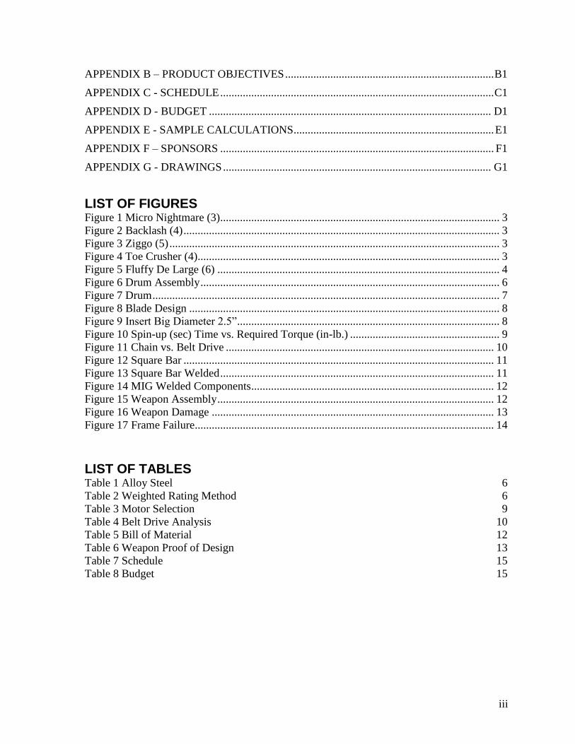
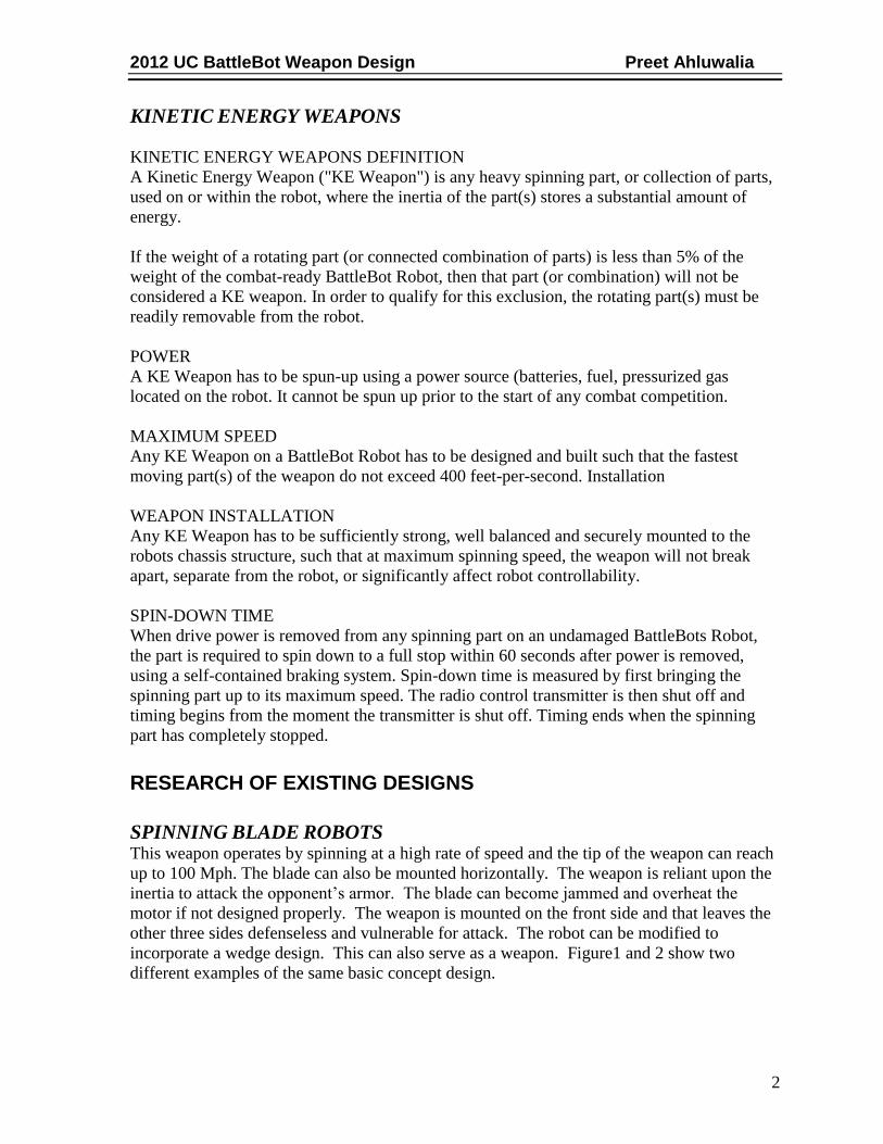
SPINNING BLADE ROBOTS This weapon operates by spinning at a high rate of speed and the tip of the weapon can reach
up to 100 Mph. The blade can also be mounted horizontally. The weapon is reliant upon the
inertia to attack the opponent’s armor. The blade can become jammed and overheat the
motor if not designed properly. The weapon is mounted on the front side and that leaves the
other three sides defenseless and vulnerable for attack. The robot can be modified to
incorporate a wedge design. This can also serve as a weapon. Figure1 and 2 show two
different examples of the same basic concept design.
2012 UC BattleBot Weapon Design Preet Ahluwalia
3
Figure 1 Micro Nightmare (3)
Figure 2 Backlash (4)
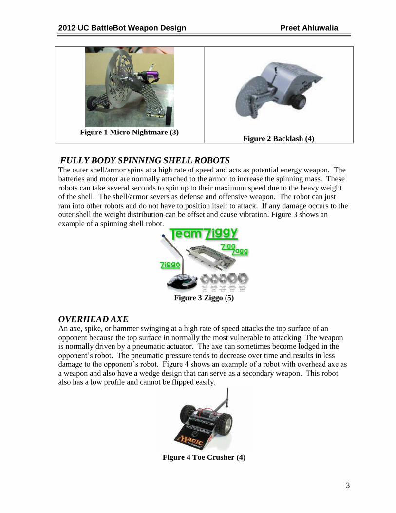
FULLY BODY SPINNING SHELL ROBOTS The outer shell/armor spins at a high rate of speed and acts as potential energy weapon. The
batteries and motor are normally attached to the armor to increase the spinning mass. These
robots can take several seconds to spin up to their maximum speed due to the heavy weight
of the shell. The shell/armor severs as defense and offensive weapon. The robot can just
ram into other robots and do not have to position itself to attack. If any damage occurs to the
outer shell the weight distribution can be offset and cause vibration. Figure 3 shows an
example of a spinning shell robot.
Figure 3 Ziggo (5)
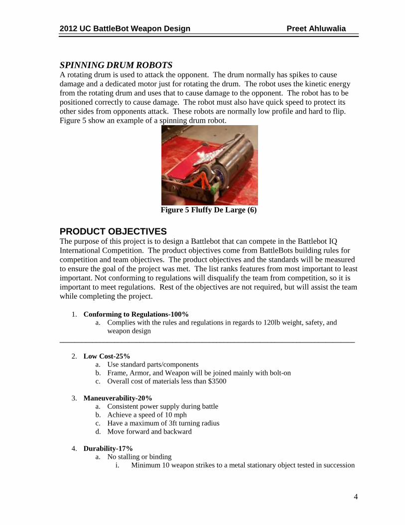
OVERHEAD AXE An axe, spike, or hammer swinging at a high rate of speed attacks the top surface of an
opponent because the top surface in normally the most vulnerable to attacking. The weapon
is normally driven by a pneumatic actuator. The axe can sometimes become lodged in the
opponent’s robot. The pneumatic pressure tends to decrease over time and results in less
damage to the opponent’s robot. Figure 4 shows an example of a robot with overhead axe as
a weapon and also have a wedge design that can serve as a secondary weapon. This robot
also has a low profile and cannot be flipped easily.
Figure 4 Toe Crusher (4)
2012 UC BattleBot Weapon Design Preet Ahluwalia
4
SPINNING DRUM ROBOTS A rotating drum is used to attack the opponent. The drum normally has spikes to cause
damage and a dedicated motor just for rotating the drum. The robot uses the kinetic energy
from the rotating drum and uses that to cause damage to the opponent. The robot has to be
positioned correctly to cause damage. The robot must also have quick speed to protect its
other sides from opponents attack. These robots are normally low profile and hard to flip.
Figure 5 show an example of a spinning drum robot.
Figure 5 Fluffy De Large (6)
PRODUCT OBJECTIVES The purpose of this project is to design a Battlebot that can compete in the Battlebot IQ
International Competition. The product objectives come from BattleBots building rules for
competition and team objectives. The product objectives and the standards will be measured
to ensure the goal of the project was met. The list ranks features from most important to least
important. Not conforming to regulations will disqualify the team from competition, so it is
important to meet regulations. Rest of the objectives are not required, but will assist the team
while completing the project.
1. Conforming to Regulations-100%
a. Complies with the rules and regulations in regards to 120lb weight, safety, and
weapon design
_________________________________________________________________________________
2. Low Cost-25%
a. Use standard parts/components
b. Frame, Armor, and Weapon will be joined mainly with bolt-on
c. Overall cost of materials less than $3500
3. Maneuverability-20%
a. Consistent power supply during battle
b. Achieve a speed of 10 mph
c. Have a maximum of 3ft turning radius
d. Move forward and backward
4. Durability-17%
a. No stalling or binding
i. Minimum 10 weapon strikes to a metal stationary object tested in succession

2012 UC BattleBot Weapon Design Preet Ahluwalia
5
b. Damage to weapon will not prevent weapon from being used
i. Minimum 10 weapon strikes to a metal stationary object tested in succession
c. Damage to armor will not prevent BattleBot from competing
i. Minimum 10 weapon strikes to a metal stationary object tested in succession
5. Weapon Damage Capacity-13%
a. Weapon start-up time less than 5 seconds
b. Capable of inflicting debilitating damage with weapon
c. Prevention of stalling or binding
i. Minimum 10 weapon strikes to a metal stationary object tested in succession
d. Damage to weapon will not prevent weapon from being used
i. Minimum 10 weapon strikes to a metal stationary object tested in succession
6. Ease of Maintenance-11%
a. Use standard parts/components
b. Repairs will be done in 20 minutes or less
c. Built with a Modular Frame, Armor, and interchangeable Weapon
d. Built with standard tools
e. Chain and belt drives will be adjustable with a tensioner
7. Ease of Manufacturing & Assembly-7%
a. Use Standard Parts
b. BattleBot frame and armor joined mainly with bolt-on
c. Built with standard tools
8. Radio Control-6%
a. Control systems properly shielded to prevent static “Noise” interference to the
communication between the controller and the BattleBot
b. Control range minimum distance of 70ft
c. Simple drive controls to allow for anyone to operate
i. Control left and right joy stick will operate independently
9. Appearance-1% a. BattleBot will have visible representation of our sponsors
b. BattleBot is intimidating
WEAPON DESIGN PROCESS A spinning drum was selected as a weapon for the Battlebot. It is durable and reliable than
most other weapons. It causes more damage than the overhead axe and the spinning blade
because the surface area that will be in contact with the other Battlebot is bigger. Figure 6
shows the assembly drawing of the drum and other major parts.

2012 UC BattleBot Weapon Design Preet Ahluwalia
6
Figure 6 Drum Assembly
MATERIAL SELECTION Before designing the drum and blades, material was selected. The list of materials was
narrowed down to three alloys shown in Table 1. The material choices were narrowed due to
their availability in rods, rod sizes and weldability of the material.
AISI
Number
Condition Tensile Strength
(ksi)
Yield Strength
(ksi)
Brinell Hardness
(HB)
4320 SWQT 300 218 178 429
4320 DOQT 300 151 97 302
4620 SWQT 300 119 83 277
4620 DOQT 300 122 77 248
8620 SWQT 300 188 149 388
8620 DOQT 300 133 83 269
Table 1 Alloy Steel
Weighted rating method was used to determine the best suitable choice. Table 2 shows
weighted rating method used to narrow the list down to one. The material selected was the
one with the highest weighted total, 8620 Alloy Steel. The main deciding factor was price.
Even though 8620 is the more expensive than the other two alloys, the Battlebot team was
able to get a discount making it cheaper than the other two alloys. The blades will be welded
on the drum and therefore the chosen material will be the same for drum and blades.
4620 Alloy Steel 4320 Alloy Steel 8620 Alloy Steel
CRITERIA Weight Score Weight Score Weight Score Weight
Price 0.45 4.00 1.80 3.00 1.35 5.00 2.25
Strength 0.25 3.00 0.75 5.00 1.25 4.00 1.00
Weight 0.25 3.00 0.75 3.00 0.75 3.00 0.750
Easy to
Weld
0.05 4.00 0.20 4.00 0.20 4.00 0.200
Total 1.00 3.50 3.55 4.20
Table 2 Weighted Rating Method
2012 UC BattleBot Weapon Design Preet Ahluwalia
7
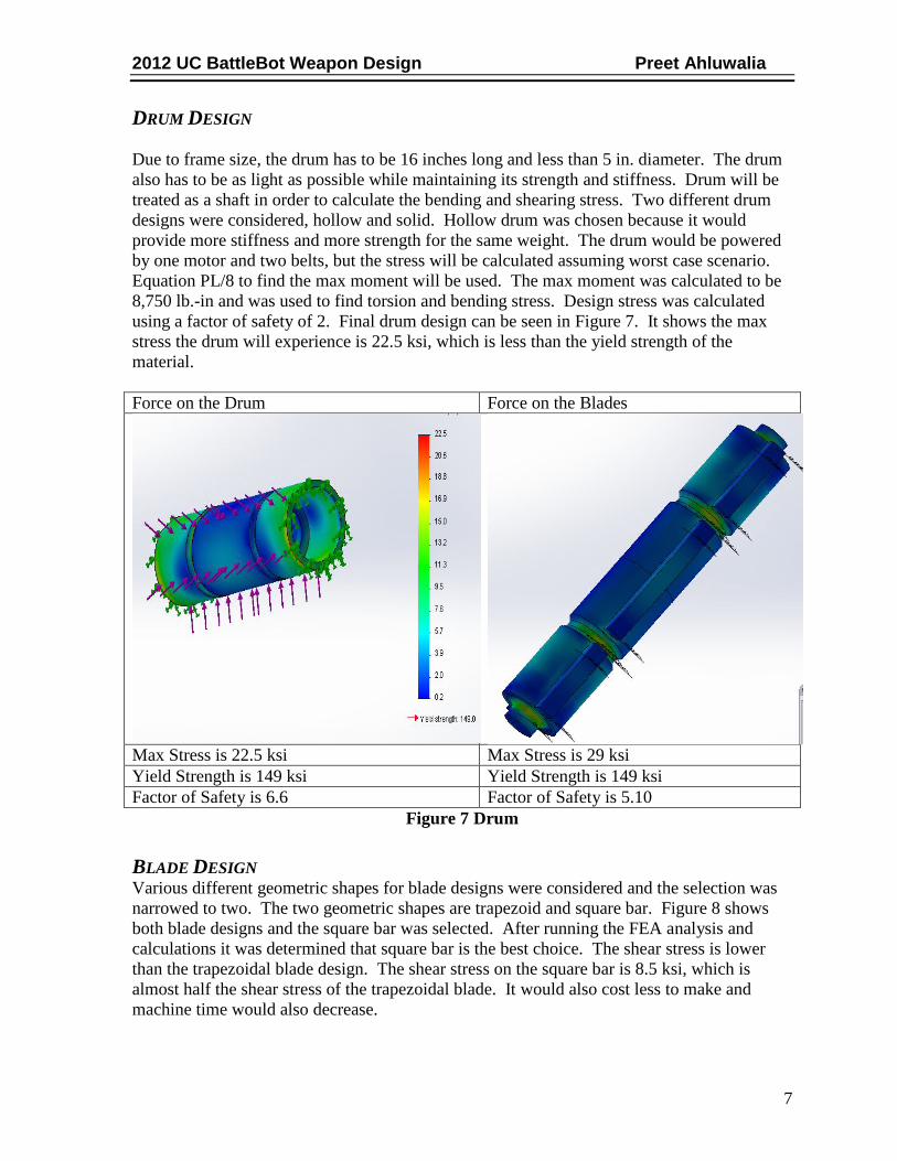
DRUM DESIGN
Due to frame size, the drum has to be 16 inches long and less than 5 in. diameter. The drum
also has to be as light as possible while maintaining its strength and stiffness. Drum will be
treated as a shaft in order to calculate the bending and shearing stress. Two different drum
designs were considered, hollow and solid. Hollow drum was chosen because it would
provide more stiffness and more strength for the same weight. The drum would be powered
by one motor and two belts, but the stress will be calculated assuming worst case scenario.
Equation PL/8 to find the max moment will be used. The max moment was calculated to be
8,750 lb.-in and was used to find torsion and bending stress. Design stress was calculated
using a factor of safety of 2. Final drum design can be seen in Figure 7. It shows the max
stress the drum will experience is 22.5 ksi, which is less than the yield strength of the
material.
Force on the Drum Force on the Blades
Max Stress is 22.5 ksi Max Stress is 29 ksi
Yield Strength is 149 ksi Yield Strength is 149 ksi
Factor of Safety is 6.6 Factor of Safety is 5.10
Figure 7 Drum
BLADE DESIGN Various different geometric shapes for blade designs were considered and the selection was
narrowed to two. The two geometric shapes are trapezoid and square bar. Figure 8 shows
both blade designs and the square bar was selected. After running the FEA analysis and
calculations it was determined that square bar is the best choice. The shear stress is lower
than the trapezoidal blade design. The shear stress on the square bar is 8.5 ksi, which is
almost half the shear stress of the trapezoidal blade. It would also cost less to make and
machine time would also decrease.

2012 UC BattleBot Weapon Design Preet Ahluwalia
8
Square Bar Trapezoidal Bar
Max Stress is 8.60 ksi Max Stress is 15.8 ksi
Yield Strength is 149 ksi Yield Strength is 149 ksi
Factor of Safety is 17.3 Factory of Safety is 9.40
Figure 8 Blade Design
INSERT DESIGN The insert will be welded to the drum. There are two inserts one on each side the drum. The
main purpose of the insert is diameter reduction. One side of the insert will go inside the
hollow drum and the other side will go inside the frame. Figure 9 represents the insert and
the small diameter will go inside the frame, where it will be able to spin freely. The big
diameter is 2.5 inches and the small diameter is 2.0 inches.
Figure 9 Insert Big Diameter 2.5”
WEAPON DRIVE CONFIGURATION AND DESIGN According to competition rules, the maximum speed of any moving part is 24,000 ft/min.
Since the blade will be welded on the surface of the drum, the top surface of the blade will be
the fastest moving part. The max speed allowed is 20,300 RPM. Sample calculations are
shown in Appendix C.
REQUIRED TORQUE Before selecting a motor, the torque required to rotate the weapon was analyzed. The mass

2012 UC BattleBot Weapon Design Preet Ahluwalia
9
and the desired rotational velocity are known. The equation torque (T) = inertia (i) * angular
acceleration (α) was used to calculate the required torque. Figure 10 shows the torque
required in relation to spin-up time.
Figure 10 Spin-up (sec) Time vs. Required Torque (in-lb.)
MOTOR SELECTION Due to weight limitations AC motors were not an option because it would require extra
electronics and a transformer. This would add more weight to the robot. Brush DC motors
provide more torque then Brushless DC motors for the same weight. Table 3 compares four
different DC brush motors. Amp Flow A28-400 was selected to drive the weapon. It has
more horse power and amps then the other motors. It weighs less than A40-300 while
providing more power.
Name Motor Type
Peak hp
Peak torque (oz-in)
voltage (v) RPM Weight (lbs)
No load Amps
Amp Flow A28-400 Brush DC 4.5 3720 24 4900 6.9 4.5
Amp Flow A28-150 Brush DC 3 1970 24 6000 3.8 3.4
Amp Flow A40-300 Brush DC 3.8 3840 24 4000 11.9 3.5
Amp Flow E30-400 Brush DC 2.1 1500 24 5700 5.9 3.1
Table 3 Motor Selection
0
50
100
150
200
250
300
350
0 0.2 0.4 0.6 0.8 1 1.2
To
rqu
e (i
n-l
b)
Time (sec)
Spin-up Time vs. Torque @3600
RPM

2012 UC BattleBot Weapon Design Preet Ahluwalia
10
BELT-DRIVE VS. CHAIN
Chain Drive Belt Drive
Figure 11 Chain vs. Belt Drive
Two methods were considered to spin the drum. Chain drives are very efficient, tend to have
lower bearing loads than belts, offer higher HP on small diameter and tend to not slip. A belt
drive tends to slip, has a larger spin up and spin down time, offers less HP than chain drives
and can operate and high RPM. Belt drive was chosen to drive the drum because it offers
more advantages for this application than chain drive. The slip is necessary in order to
reduce the strain on the motor during spin up and spin down times. Slip is also required
when the weapon makes contact with the other Battlebot, so the motor will not get damaged.
Chain and Belt drive in Figure 11 are shown for illustration purposes only.
BELT DRIVE ANALYSIS AND DESIGN Frame limitations, motor and weapon parameter were considered while designing the belt
drive system. A center distance of approximately 6 in and 1:1 speed ratio was chosen. Table
4 shows the final results of the analysis. Detailed calculations are shown in Appendix E.
Operation Power 3.38 HP
Operating Torque 61.96 in-lb
Operating Motor RPM 3600 RPM
Service Factor 1.2
Speed Ratio 1:1.001
Belt Speed 2449.2 Ft/min
Drive Sheave Diameter 2.6 in
Center Distance 5.9 in
Table 4 Belt Drive Analysis
FABRICATION AND ASSEMBLY The fabrication for the weapon was done at Setco (8) machine shop. The material and
machine time was donated by Setco (8). Welding operations were done at the College of
Engineering & Applied Science victory parkway campus.

2012 UC BattleBot Weapon Design Preet Ahluwalia
11
BLADES The alloy steel square bar was ordered stock for the blades and was case hardened to
the depth of .002 in shown is Figure 12. The blades are TIG welded on top of the drum as
seen in Figure 13.
Figure 12 Square Bar Figure 13 Square Bar Welded
DRUM A 4 inch round bar made from 8620 alloy steel was used to create the drum. The bar stock
was loaded into Okuma LR35 CNC machine and series of operations were used to machine
the drum. First, face off operation was used to cut the stock to exact length. Next, the bar
stock was rough turned and the diameter was reduced to approximately 3.55 inches and the
diameter was further reduced to 3.5 inches by using the finishing operation. Next, the O.D.
grooving operations was used to make belt grooves in the drum. Afterwards, life tool end
milling operation was used for facing the drum where the blades will be welded. Lastly, a
hole was drilled in order to bore out the material from inside the drum.
INSERT Both of the inserts were machined from 8620 alloy steel 4 inch round bar. Okuma LR35
CNC machine was used to machine the inserts. Face off cutting operation was used to cut
the round bar to exact length. Next, turning operation was used to reduce the diameter to 2.5
inches. Then, hole was drilled and material was removed using boring operation.
JOINING The joining of three parts of the weapon was done in the welding shop at University of
Cincinnati victory parkway campus. TIG welding process was used to weld the teeth and
MIG welding process was used to weld the inserts to the drum body. Figure 14 shows teeth
and insert welded to the drum.

2012 UC BattleBot Weapon Design Preet Ahluwalia
12
Figure 14 MIG Welded Components
ASSEMBLY The weapon was assembled at the College of Engineering & Applied Science victory
parkway campus. No special tools were required to assemble the weapon. Figure 15 shows
the weapon assembly. The rotors on the inserts fit inside the bushings that are in the frame of
the Battlebot. Table 5 shows the bill of material for the weapon.
Figure 15 Weapon Assembly
Weapon Bill of Material
Component Quantity Part Number Description
Motor 1 S28-400 Mag
Motor
Drive motor
V-Belt 2 V-belts
Motor Pulley 2 6204k181 2.5” O.D.
Weapon Drum 1 Fabrication 8620 Steel-drum
Weapon Inserts 2 Fabrication 8620 Steel-insert
Weapon Blades 6 Fabrication 8620 Steel-
blades
Table 5 Bill of Material
TESTING AND COMPETITION The actual proof of design for weapon system was tested at the 2013 ComBots competition
in San Mateo, California. The ComBots competition was part of Robogames from April
19-21. Table 6 shows the proof of design criteria for the weapon.

2012 UC BattleBot Weapon Design Preet Ahluwalia
13
DESIGN
CRITERIA
FEATURES CRITERIA
MET
Durable Weapon will operate, even after being damaged Yes
Speed Operating Speed will be reached under one second Yes
Damaging
Capacity
The weapon will inflict visible damage Yes
Maintenance No special tools required and repairs will be under 20 minutes Yes
Table 6 Weapon Proof of Design
PROOF OF WEAPON DESIGN Weapon durability and strength was tested during competition. During the first battle, frame
of the bot broke as shown in Figure 16. This failure left the weapon unable to operate
correctly during battle. Before the weapon was incapacitated, it functioned as designed. The
weapon reached its operational speed under one second. The weapon was able to inflict
visible damage to the other robot, but not enough to incapacitate the opponent. Figure 16
shows damage that occurred to the blade after the first battle and no repair and maintenance
was necessary.
Figure 16 Weapon Damage
There were 36 teams that competed in the 120 pound division including the 2013 UC
BattleBot team. Arena conditions were not satisfactory due to the uneven surface of the
arena floor. The arena floor was 2 feet from the ground and consisted of 2 ft x 3 ft plates that
made the entire floor. The uneven surface caused the bot to drag on the floor and duct tape
was used to increase the wheels diameter as a quick fix.
Drivetrain performed as designed. No adjustment, repair or maintenance on the drivetrain
and wheels were required, except duct tape on the wheels. The only problem was that drive
motors provided more torque than necessary which resulted in poor control and 60% of
winning a match is the ability to control the BattleBot.
2012 UC BattleBot Weapon Design Preet Ahluwalia
14
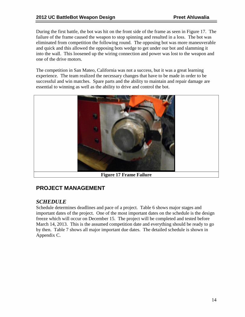
During the first battle, the bot was hit on the front side of the frame as seen in Figure 17. The
failure of the frame caused the weapon to stop spinning and resulted in a loss. The bot was
eliminated from competition the following round. The opposing bot was more maneuverable
and quick and this allowed the opposing bots wedge to get under our bot and slamming it
into the wall. This loosened up the wiring connection and power was lost to the weapon and
one of the drive motors.
The competition in San Mateo, California was not a success, but it was a great learning
experience. The team realized the necessary changes that have to be made in order to be
successful and win matches. Spare parts and the ability to maintain and repair damage are
essential to winning as well as the ability to drive and control the bot.
Figure 17 Frame Failure
PROJECT MANAGEMENT
SCHEDULE Schedule determines deadlines and pace of a project. Table 6 shows major stages and
important dates of the project. One of the most important dates on the schedule is the design
freeze which will occur on December 15. The project will be completed and tested before
March 14, 2013. This is the assumed competition date and everything should be ready to go
by then. Table 7 shows all major important due dates. The detailed schedule is shown in
Appendix C.

2012 UC BattleBot Weapon Design Preet Ahluwalia
15
Major Milestones
Description Proposed
Date Actual Date Design Freeze 12/15/2012 12/15/2012 Purchase Parts 01/01/2013 01/01/2013
Robot Assembly 02/24/2013 02/24/2013 Troubleshooting 03/14/2013 03/14/2013
Tech. Expo 04/06/2013 04/06/2013 Competition 04/19/2013 04/19/2013 Final Report 04/23/2013 04/23/2013
Table 7 Schedule
BUDGET The budget in based on the money received for sponsors. One of the major expenses is
machining which will be covered by Cincinnati Milacron because they are giving free
machining time. The other major expense is parts and materials which will be covered by
various sponsors. The budget is shown in Table 8 and the actual budget can be seen in
Appendix D
Table 8 Budget
CONCLUSION AND RECOMMENDATIONS As a team we wanted to design, assemble and compete in the 2013 ComBots competition and
that is what we did. There were 35 other teams and most had prior experience in building
and competition with BattleBots. This was a great learning experience as a whole, the team
witnessed first had how other teams bots were designed and how they worked in the pits to
make repairs and maintain their bots. This year’s competition was a mixture of 60 lbs., 120
lbs. and 220 lbs. divisions and the arena had no hazards.
The team had no prior experience in regards to building and competing with BattleBots. This
project requires knowledge of electrical and mechanical systems. Forming a team and
finding sponsors as early as possible is essential to the overall success of the team. If a
sponsor is donating material and/or machine time, be sure to collect the donated material or
get the material machined to specifications as soon as possible. Some companies will delay
Proposed Budget
Price $ Type Explained
$500.00 Hardware Nuts, Bolts, Wires, Electrical Accessories
$1,200.00 Materials Frame, Steel
$2,500.00 Parts Batteries, Motors, Electronics, Belts, Chains, Wheels
$2,500.00 Machining Weapon, Frame
$2,136.00 Travel Expenses Hotel, Gas, Food
$500.00 Competition Fees Entry Fee
$1,640.00 Misc.
Total $
$10,976.00

2012 UC BattleBot Weapon Design Preet Ahluwalia
16
or not come through with their promise as the 2013 UC BattleBot team experienced both.
It is important for the team to work together to make the bot as robust as possible. As the
2013 UC BattleBot team experienced, failure of any one of the components will result in a
loss during competition and failure of the team. Research is also important because no
design perfect. It is important to know the weaknesses of other bots and how to defend the
weakness of one’s own bot as well.
Testing is also important in order to be successful in the competition. At least 10 hours of
driving should be done in order to master control of the bot. Other testing methods can
include ramming the robot at full speed into a wall. The bot should function at 100% of its
capacity after hitting the wall. All electrical components and drive components should
function as designed. The frame and body should receive minimal damage as well.
Biggest dilemma for any BattleBot is strength vs. weight. Future teams should look into
lighter motors; brushless motor should be looked into. Brushless motors weigh less but cost
more. Brush DC motor for the weapon was used because it costs less and it provides more
torque. Most bots do attack the top of the bot, so a light weight material such as Plexiglas
can be used.
The bot will encounter spinning shell and/or spinning drum bots. The weapon should be
designed to work even after getting hit by these bots; and the frame and armor should be able
to withstand damage from these bots. If designing a spinning weapon, the operating rpm
should be around 7000 rpm or more. If a wedge design is used, it should be able to with
stand being hit repeatedly. A wedge design is most effective against spinning shell bots
because it can flip them, but the wedge must be able to withstand a hit from the spinning
shell.
CONCLUSION The UC BattleBots should join an official club in order to be successful in the future. This
would also help build experience for the freshmen and sophomores and give them an
opportunity to learn from the seniors and improve on previous years designs. Being in an
official club will also increase funding.
For future teams I would recommend a spinning shell design with a spring damper system
and bolt on blades that can be replaced easily. LED’s mounted towards the front and back
can assist in driving and control. The person steering can quickly find out which way the bot
is facing while spinning.
2012 UC BattleBot Weapon Design Preet Ahluwalia
17
WORKS CITED 1. BattleBots Tournament Rules. www.BattleBots.com. [Online] BattleBots Inc., 2009.
[Cited: September 5, 2012.]
2. Smentowski, Jim. Team Nightmare. RobotCombat.Com. [Online] 2006. [Cited:
September 9, 2012.] http://www.robotcombat.com/micronightmare.html.
3. AlexGrFan97. Battlebots 2.0 Toe Crusher vs Backlash. Youtube. [Online] March 13,
2012. [Cited: October 2, 2012.] http://www.youtube.com/watch?v=4NYLJY2qvII.
4. Ziggy, Team. Team Ziggy. TeamZiggy.Com. [Online] [Cited: September 9, 2012.]
http://www.teamziggy.com/index.html.
5. Dallinzzz. Witch Doctor vs Fluffy De Large grudge match. youtube.com. [Online]
February 28, 2011. [Cited: September 10, 2012.]
http://www.youtube.com/watch?v=uN4Yqtwb0Pc.
6. Copas, Travie. HOw to build a winning Battlebot. s.l. : Shaun Egan, September 17, 2012.
7. Egan, Shaun. How to build a winning Battlebot. [interv.] Travis Copas. Cincinnati,
September 17, 2012.

Appendix A1
APPENDIX A –RESEARCH
Micro Nightmare
Ziggo
- Description
This robot uses its blade to tear through the opponent’s
armor. The weapon can be mounted vertically or
horizontally. The weapon spins at high rate of speed and
relies on inertia of the weapon to tear through armor
Agile, but vulnerable
Expensive Blade,
but strong
Weapon designed to
tear through
opponent armor
Weapon can be
oriented horizontally
for low ground
clearance chassis
The sides and back
is vulnerable to
attack
Description
The robot uses the outer shell/armor as a weapon. The
robot is designed to spin and provide protection on all side
of the robot simultaneously.
Short start up time
Attacks and defends
simultaneously
Weight balance
must be maintained,
or excessive
vibrations can occur.
Vulnerable to
Wedge and Clamp
Bots.
Micro Nightmare
http://www.robotcombat.co
m/micronightmare.html
Accessed Sept 9, 2012
Ziggo
http://www.teamziggy.com/i
ndex.html
Accessed Sep 9, 2012
Appendix A2
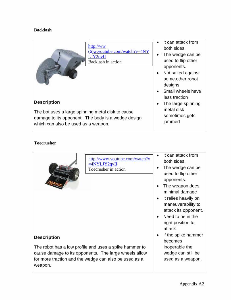
Backlash
Toecrusher
Description
The bot uses a large spinning metal disk to cause
damage to its opponent. The body is a wedge design
which can also be used as a weapon.
It can attack from
both sides.
The wedge can be
used to flip other
opponents.
Not suited against
some other robot
designs
Small wheels have
less traction
The large spinning
metal disk
sometimes gets
jammed
Description
The robot has a low profile and uses a spike hammer to
cause damage to its opponents. The large wheels allow
for more traction and the wedge can also be used as a
weapon.
It can attack from
both sides.
The wedge can be
used to flip other
opponents.
The weapon does
minimal damage
It relies heavily on
maneuverability to
attack its opponent.
Need to be in the
right position to
attack.
If the spike hammer
becomes
inoperable the
wedge can still be
used as a weapon.
http://ww
(6)w.youtube.com/watch?v=4NY
LJY2qvII
Backlash in action
http://www.youtube.com/watch?v
=4NYLJY2qvII
Toecrusher in action
Appendix A3
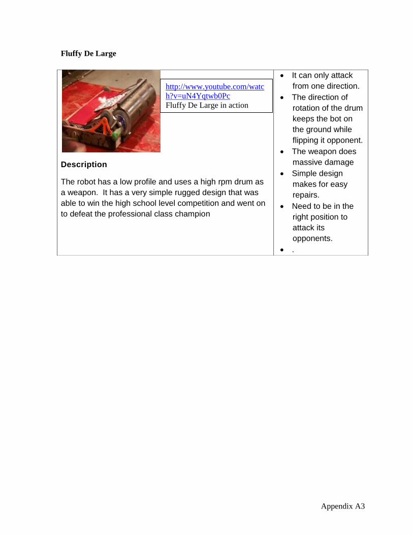
Fluffy De Large
Description
The robot has a low profile and uses a high rpm drum as
a weapon. It has a very simple rugged design that was
able to win the high school level competition and went on
to defeat the professional class champion
It can only attack
from one direction.
The direction of
rotation of the drum
keeps the bot on
the ground while
flipping it opponent.
The weapon does
massive damage
Simple design
makes for easy
repairs.
Need to be in the
right position to
attack its
opponents.
.
http://www.youtube.com/watc
h?v=uN4Yqtwb0Pc
Fluffy De Large in action
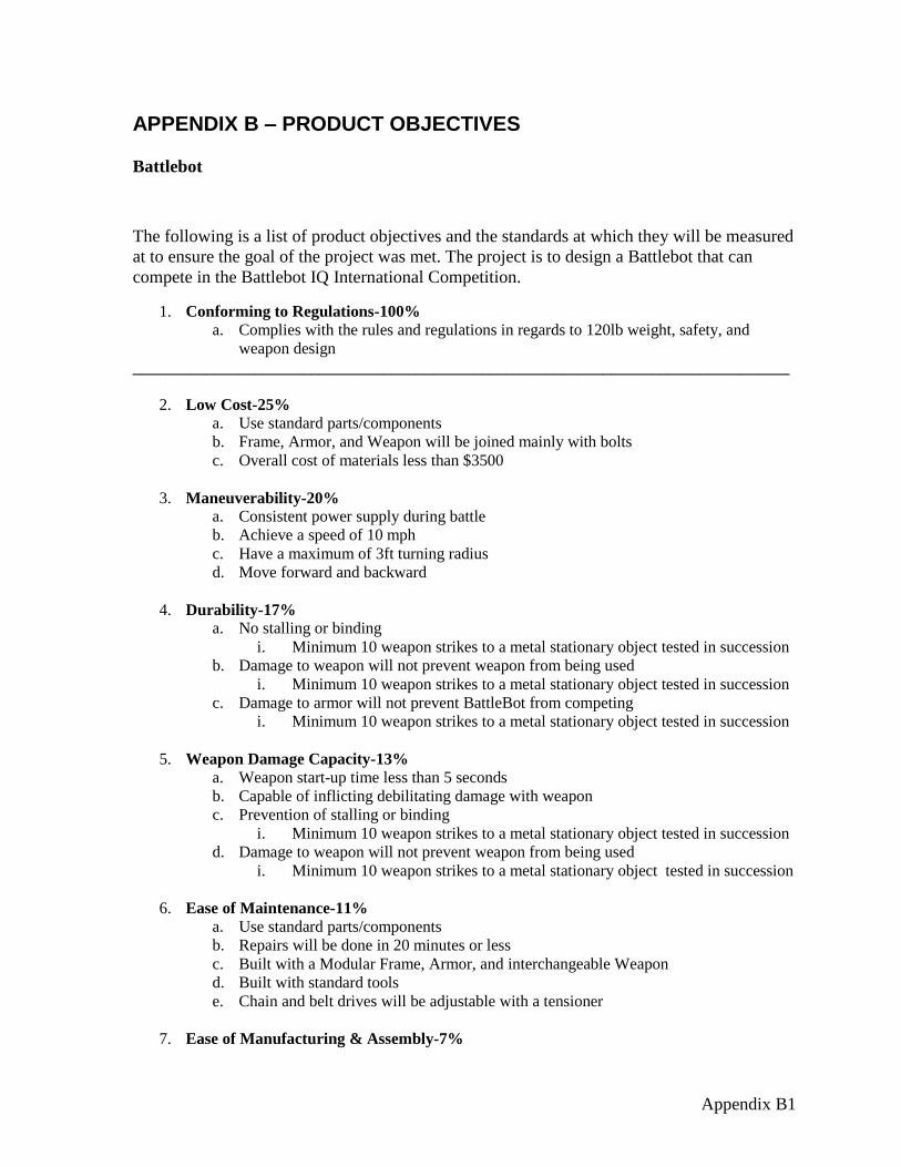
Appendix B1
APPENDIX B – PRODUCT OBJECTIVES
Battlebot
The following is a list of product objectives and the standards at which they will be measured
at to ensure the goal of the project was met. The project is to design a Battlebot that can
compete in the Battlebot IQ International Competition.
1. Conforming to Regulations-100%
a. Complies with the rules and regulations in regards to 120lb weight, safety, and
weapon design
_________________________________________________________________________________
2. Low Cost-25%
a. Use standard parts/components
b. Frame, Armor, and Weapon will be joined mainly with bolts
c. Overall cost of materials less than $3500
3. Maneuverability-20%
a. Consistent power supply during battle
b. Achieve a speed of 10 mph
c. Have a maximum of 3ft turning radius
d. Move forward and backward
4. Durability-17%
a. No stalling or binding
i. Minimum 10 weapon strikes to a metal stationary object tested in succession
b. Damage to weapon will not prevent weapon from being used
i. Minimum 10 weapon strikes to a metal stationary object tested in succession
c. Damage to armor will not prevent BattleBot from competing
i. Minimum 10 weapon strikes to a metal stationary object tested in succession
5. Weapon Damage Capacity-13%
a. Weapon start-up time less than 5 seconds
b. Capable of inflicting debilitating damage with weapon
c. Prevention of stalling or binding
i. Minimum 10 weapon strikes to a metal stationary object tested in succession
d. Damage to weapon will not prevent weapon from being used
i. Minimum 10 weapon strikes to a metal stationary object tested in succession
6. Ease of Maintenance-11%
a. Use standard parts/components
b. Repairs will be done in 20 minutes or less
c. Built with a Modular Frame, Armor, and interchangeable Weapon
d. Built with standard tools
e. Chain and belt drives will be adjustable with a tensioner
7. Ease of Manufacturing & Assembly-7%
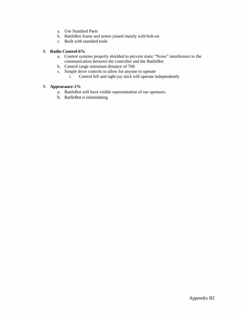
Appendix B2
a. Use Standard Parts
b. BattleBot frame and armor joined mainly with bolt-on
c. Built with standard tools
8. Radio Control-6%
a. Control systems properly shielded to prevent static “Noise” interference to the
communication between the controller and the BattleBot
b. Control range minimum distance of 70ft
c. Simple drive controls to allow for anyone to operate
i. Control left and right joy stick will operate independently
9. Appearance-1%
a. BattleBot will have visible representation of our sponsors. b. BatlleBot is intimidating

Appendix C1
APPENDIX C - SCHEDULE
Summer Quarter
Week
Date 5/27 6/2 6/3 6/9 6/10 6/16 6/17 6/23 6/24 6/30 7/1 7/7 7/8 7/14 7/15 7/21 7/22 7/28 7/29 8/4 8/5 8/11 8/12 8/18 8/19 8/25
Problem Statement
Create Sponsorship Letters
Send out Sponsorship Letters
Fall Semester
Week
Date 8/26 9/1 9/2 9/8 9/9 9/15 9/16 9/22 9/23 9/29 9/30 10/6 10/7 10/13 10/14 10/20 10/21 10/27 10/28 11/3 11/4 11/10 11/11 11/17 11/18 11/24 11/25 12/1 12/2 12/8 12/9 12/15
Contact Information 8/31
Actual
Research
Customer Features
Sponsor Agreement Letter
Product Objectives
Budget
Schedule
Appendices
First Draft of Report
Proof of Design Agreement
Conceptial Design
Final Semester Report
Order Parts and Material 12/15
Actual
Final Design and Drawings
Design Freeze 12/15
Actual
Register for Competition
14
10/23 - 12/15
2012
8/26 - 9/11
16
9/27 - 10/9
Actual
Actual
15
Actual
8/26 - 9/11
2 3 10
73
9
9
6/1 - 6/30
5/30
4 5 6 7 8
Actual
2012
1
Actual
Actual
Actual
Actual
13
8/26 - 9/18
81 2 4
11 12
5 6
Actual
10/4 - 10/23
10/4 - 10/9
Actual
Actual
10/4 - 10/30
10
6/30 - 7/30
9/27 - 10/9
Actual
9/20 - 10/9
Actual
Actual
10/4 - 10/23
10/4 - 10/23
Actual
11/14 - 3/1
Actual
Winter Break
Week
Date 12/15 12/21 12/22 12/28 12/29 1/4 1/5 1/7
Register for Competition
Order Parts and Material
1 2 43
11/14 - 3/1
2012-2013
Spring Semester
Fall SemesterFall Semester
Summer Quarter
Legend
Actual DatesPropsed Dates
Actual
Actual
Spring Semester
Summer Quarter
Winter BreakWinter Break

Appendix C2
Spring Semester
Week 3
Date 1/7 1/13 1/14 1/20 1/21 1/27 1/28 2/3 2/4 2/10 2/11 2/17 2/18 2/24 2/25 3/2 3/3 3/9 3/10 3/16 3/17 3/23 3/24 3/30 3/31 4/6 4/7 4/13 4/14 4/20 4/21 4/27 4/28 5/4
Order Parts and Material
Manufacture
Assembly
Manufacture
Assembly
Manufacture
Assembly
Assembly
Registration
Test/ Troubleshoot
Competition
Faculty Oral Report 2/1
Actual
Report to Advisor 2/6
Final Oral Report
Final Written Report
Commencement 4/27
Actual
3/10 - 3/23
3/10 - 3/23
3/24 - 4/18
Assembly and Competition
14 15 1610 112 4
Frame/ Armor
Actual
2/20 - 3/9
2013
1
Actual
17
Weapon
Electrical System
Actual
Actual
2/20 - 3/9
3/10 - 3/23
137 8 9 125 6
3/10 - 3/23
Actual
Actual
Actual
12/21 - 2/8
Drivetrain
Actual
Actual
11/14 - 3/1
Actual
Actual
Actual
4/18 - 4/22
4/18 - 4/22
Actual
4/13 - 4/15
Actual

Appendix D1
APPENDIX D - BUDGET
Proposed Budget
Price $ Type Explained
$500.00 Hardware Nuts, Bolts, Wires, Electrical Accessories
$1,200.00 Materials Frame, Steel
$2,500.00 Parts Batteries, Motors, Electronics, Belts, Chains, Wheels
$2,500.00 Machining Weapon, Frame
$2,136.00 Travel Expenses Hotel, Gas, Food
$500.00 Competition Fees Entry Fee
$1,640.00 Misc.
Total $
$10,976.00
Actual Budget:
Frame Expences: -$
Weapon Expenses: 606.21$
Drivetrain Expences: 947.47$
Electronics Expences: -$
General Materials: 236.70$
Sub Total of Material: 1,790.38$
Travel Total Sheet 3: 2,136.00$
Overall Expence Total: 3,926.38$
Total In Account: 2,700.00$
Total Left Over: (1,226.38)$
Expense Per Person: (306.60)$

Appendix E1
APPENDIX E - SAMPLE CALCULATIONS The impulse force was used to calculate the stresses to ensure that the material selected
would not fail. It was also used to design the drum. This calculations is needed to select the
material for the weapon.
Impulse Force Impulse force was calculated to determine the forces that will be encountered during
competition.
Assumptions
Robot 2 is stationary
Impulse time is 0.01 seconds
Known Information
Robot 1 and Robot 2 weigh 120 lb. each
Robot 1 is moving at 13.2 ft. /s
Mass (m) = weight/gravity
m = 120lbs/32.2 ft/
m=3.73 slugs
Impulse (I) = FΔt = Δp = mΔv = -
I = 3.73 slugs * 13.2 ft./s - 3.73 slugs * 0 ft/s
I = 49.2 lb. sec
Force (F) = I/Δt
F= 49.2 lb. sec / 0.01 sec
F = 4,923 lb.
Drum (Shaft) Calculations Assumes worst case scenario
Safety Factor (N) = 2
Yield strength ( ) = 149,000 psi
Tensile strength (( ) = 188,000 psi
I.D. = 2.13 in
O.D. = 4.00 in
a = 7.00 in
b = 9.00 in
L = 16.0 in
Max Moment

Appendix E2
Bending Stress
Design stress ( ) =
= 188,000 psi / 2
= 94,000 psi
> , so the shaft will not bend
Torsional Stress
Psi
=
Tangential Stress
Density (γ) = .283
n = 3,600 rpm
b = Outer Radius
a = Inner Radius
Poisson Ratio (μ) = .280
Gravity (g) = 386
Angular Velocity (ω) = 2πn/60
ω=
ω= 373 rad/sec
Tangential Stress

Appendix E3
Weapon Drive Design Design Requirements
Maximum Speed of any moving part = 400 ft/sec
Know Information
Fastest moving part = Blade (4.50 in)
Circumference
C = pi*D
C= 3.14*4.50/12.0 = 1.18 ft
Maximum RPM
RPM = FPM/C
RPM = 24,000/1.18 = 20,300 rpm
V-belt Drive Design Motor Speed = 3600 rpm
Target Output Speed ( = 3600 rpm
Desired drive Sheave Ratio = 1:1
Driven sheave size ( ) = 2.63 in
Nearest standard sheave size ( ) = 2.60 in
Center Distance
< C < 3( + )
C = 5.20in
L = 2C + 1.57( + ) +
L = 20.3 in
Actual Belt Length = 20 in
C = 5.90 in
Actual Nominal speed ratio = / = 2.6/2.6 = 1.0
Actual Output Speed = 3600 rpm
.

Appendix F1
APPENDIX F – SPONSORS
.

Appendix G1
APPENDIX G - DRAWINGS Weapon Drawing
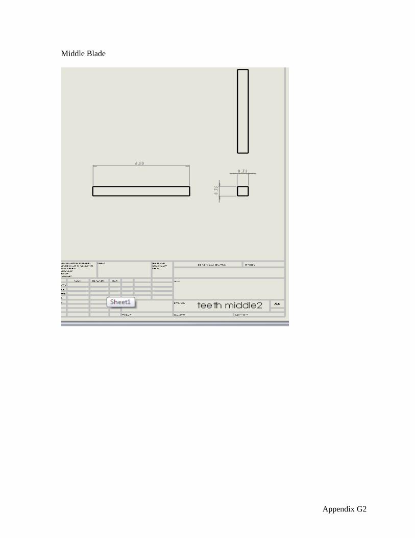
Appendix G2
Middle Blade
Appendix G3
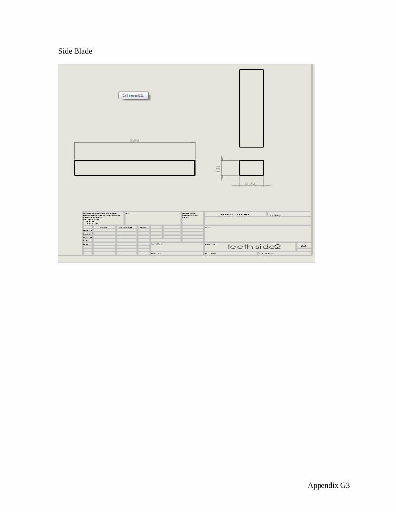
Side Blade

Appendix G4
Insert


