Mesoscale Wide-Bandwidth Linear Magnetic Actuators: An LDRD Final...
59
SANDIA REPORT SAND2004-0567 Unlimited Release Printed February 2004 Mesoscale Wide-Bandwidth Linear Magnetic Actuators: An LDRD Final Report Lawrence A. Jones Prepared by Sandia National Laboratories Albuquerque, New Mexico 87185 and Livermore, California 94550 Sandia is a multiprogram laboratory operated by Sandia Corporation, a Lockheed Martin Company, for the United States Department of Energy’s National Nuclear Security Administration under Contract DE-AC04-94AL85000. Approved for public release; further dissemination unlimited.
Transcript of Mesoscale Wide-Bandwidth Linear Magnetic Actuators: An LDRD Final...
SANDIA REPORT
SAND2004-0567 Unlimited Release Printed February 2004 Mesoscale Wide-Bandwidth Linear Magnetic Actuators: An LDRD Final Report
Lawrence A. Jones
Prepared by Sandia National Laboratories Albuquerque, New Mexico 87185 and Livermore, California 94550 Sandia is a multiprogram laboratory operated by Sandia Corporation, a Lockheed Martin Company, for the United States Department of Energy’s National Nuclear Security Administration under Contract DE-AC04-94AL85000. Approved for public release; further dissemination unlimited.

Issued by Sandia National Laboratories, operated for the United States Department of Energy by Sandia Corporation.
NOTICE: This report was prepared as an account of work sponsored by an agency of the United States Government. Neither the United States Government, nor any agency thereof, nor any of their employees, nor any of their contractors, subcontractors, or their employees, make any warranty, express or implied, or assume any legal liability or responsibility for the accuracy, completeness, or usefulness of any information, apparatus, product, or process disclosed, or represent that its use would not infringe privately owned rights. Reference herein to any specific commercial product, process, or service by trade name, trademark, manufacturer, or otherwise, does not necessarily constitute or imply its endorsement, recommendation, or favoring by the United States Government, any agency thereof, or any of their contractors or subcontractors. The views and opinions expressed herein do not necessarily state or reflect those of the United States Government, any agency thereof, or any of their contractors. Printed in the United States of America. This report has been reproduced directly from the best available copy. Available to DOE and DOE contractors from
U.S. Department of Energy Office of Scientific and Technical Information P.O. Box 62 Oak Ridge, TN 37831 Telephone: (865)576-8401 Facsimile: (865)576-5728 E-Mail: [email protected] Online ordering: http://www.doe.gov/bridge
Available to the public from
U.S. Department of Commerce National Technical Information Service 5285 Port Royal Rd Springfield, VA 22161 Telephone: (800)553-6847 Facsimile: (703)605-6900 E-Mail: [email protected] Online order: http://www.ntis.gov/help/ordermethods.asp?loc=7-4-0#online

SAND2004-0567Unlimited Release
Printed February 2004
Mesoscale Wide-Bandwidth Linear Magnetic Actuators:
An LDRD Final Report
Lawrence A. JonesElectronic Systems Center
Sandia National LaboratoriesP.O. Box 5800
Albuquerque, NM 87185–0501
Abstract
As MEMS transducers are scaled up in size, the threshold is quickly crossed to wheremagnetoquasistatic (MQS) transducers are superior for force production compared toelectroquasistatic (EQS) transducers. Considerable progress has been made increasingthe force output of MEMS EQS transducers, but progress with MEMS MQS transducershas been more modest. A key reason for this has been the difficulty implementing efficientlithographically-fabricated magnetic coil structures.
The contribution of this study is a planar multilayer polyphase coil architecture whichprovides for the lithographic implementation of efficient stator windings suitable for linearmagnetic machines. A millimeter-scale linear actuator with complex stator windings wasfabricated using this architecture.
The stators of the actuator were fabricated using a BCB/Cu process, which does notrequire replanarization of the wafer between layers. The prototype stator was limited tothin copper layers (3 µm) due to the use of evaporated metal at the time of fabrication.Two layers of metal were implemented in the prototype, but the winding architecturenaturally supports additional metal layer pairs.
It was found in laboratory tests that the windings can support very high currentdensities of 4 × 10⁹A/m2 without damage. Force production normal to the stator wascalculated to be 0.54 N/A. For thin stators such as this one, force production increasesapproximately linearly with the thickness of the windings and a six-layer stator fabricatedusing a newly implemented electroplated BCB/Cu process (six layers of 15 µm thickmetal) is projected to produce approximately 8.8 N/A.
3

Acknowledgments
The author wishes to thank the following individuals for their contributions:
• Rajen Chanchani (1745) for overseeing the implementation of the BCB/Cu HDIprocess at Sandia and the lithographic fabrication of the stator windings in thisproject.
• Denise B. Webb (1745) for fabricating the wafers.
• Donald Bethke (1745) for assisting with the wafer processing.
• Cynthia D. Blain (2339) for soldering leads on to the wafer.
• Michael P. Saavedra (14184) for cutting the permanent magnets on the micro-EDMmachine.
• Thomas K. Mayer (15252) for designing and fabricating the actuator test stand.
4

Contents
1 Introduction 7
2 Literature Review 11
3 Actuator Architecture 13
4 Fabrication Process 20
5 Results 21
6 Conclusions 23
7 Future Work 24
A Actuator Parameters 26
B Platen 28
C Wafer Design 33
D Force Modeling 41
E Dynamics 43
F Control 46
G Force Allocation 49
H Commutation 51
I Measurements 53
5

List of Figures
1 Maximum energy densities in MQS and EQS MEMS systems . . . . . . . 82 Maximum energy densities at fixed voltages in EQS MEMS systems . . . 93 Macroscale magnetically-levitated planar actuator . . . . . . . . . . . . . 104 Lithographically-fabricated linear motor stators on a wafer . . . . . . . . 135 Wafer mask drawing . . . . . . . . . . . . . . . . . . . . . . . . . . . . . 146 Armature magnet arrays embedded in the platen . . . . . . . . . . . . . 157 Mesoscale magnetically-levitated planar actuator . . . . . . . . . . . . . . 168 Single coil construction . . . . . . . . . . . . . . . . . . . . . . . . . . . . 179 Polyphase planar winding . . . . . . . . . . . . . . . . . . . . . . . . . . 1810 Polyphase planar winding with pole-to-pole connections . . . . . . . . . . 1911 Current flow in multiple layer-pair stators . . . . . . . . . . . . . . . . . 2012 Conductor dimensions in the prototype actuator . . . . . . . . . . . . . . 2213 Halbach magnet arrays mounted in the platen . . . . . . . . . . . . . . . 2814 Halbach magnet array fabrication drawing . . . . . . . . . . . . . . . . . 2915 Platen fabrication drawing . . . . . . . . . . . . . . . . . . . . . . . . . . 3116 Halbach magnet array flux density . . . . . . . . . . . . . . . . . . . . . 3217 Mask for metal layer 1 . . . . . . . . . . . . . . . . . . . . . . . . . . . . 3418 Mask for metal layer 2 . . . . . . . . . . . . . . . . . . . . . . . . . . . . 3519 Mask for metal layer 3 . . . . . . . . . . . . . . . . . . . . . . . . . . . . 3620 Mask for metal layer 4 . . . . . . . . . . . . . . . . . . . . . . . . . . . . 3721 Mask for metal layer 5 . . . . . . . . . . . . . . . . . . . . . . . . . . . . 3822 Mask for metal layer 6 . . . . . . . . . . . . . . . . . . . . . . . . . . . . 3923 Wafer detail photograph . . . . . . . . . . . . . . . . . . . . . . . . . . . 4024 Example wafer defects . . . . . . . . . . . . . . . . . . . . . . . . . . . . 4025 Vertical servo model loop transmission . . . . . . . . . . . . . . . . . . . 4726 Vertical servo model closed-loop response . . . . . . . . . . . . . . . . . . 4727 Vertical servo model step response . . . . . . . . . . . . . . . . . . . . . . 4828 Lateral positions of the magnet arrays in the platen . . . . . . . . . . . . 5029 Platen constrained to vertical motions . . . . . . . . . . . . . . . . . . . 5330 Measured vertical servo staircase response . . . . . . . . . . . . . . . . . 5431 Measured vertical servo step response . . . . . . . . . . . . . . . . . . . . 55
6
1 Introduction
Electroquasistatic (EQS) transducers are commonly used in micro-electromechanical sys-tems (MEMS), ostensibly because the fabrication of electrode plates in EQS transducersis relatively simple and is compatible with the materials and processes of silicon micro-fabrication technology. Elaborate comb structures with hundreds of electrodes have beenfabricated to increase the force produced by EQS transducers [1]. While EQS trans-ducers are electrically more efficient than magnetoquasistatic (MQS) transducers at allspeeds [2], MQS transducers can generate more force than EQS transducers at all butthe smallest sizes.
The force generated by a transducer is equal to the negative spatial gradient of theenergy W in the air gap between the armature and the stator,1
f = −∇W . (1)
Maximizing the energy W in the air gap will maximize the generated force. Equivalently,maximizing the energy density w in the air gap will maximize the generated force. In alinear MQS system, the energy density in the air gap is
wm =B2
2µo(2)
and in a linear EQS system, the energy density in the air gap is
we =εoE
2
2. (3)
If the electric field in the air gap is uniform and normal to the electrodes, then E = V/g,where V is the potential difference between the electrodes and g is the distance betweenthe electrodes. Hence,
we =εoV
2
2g2. (4)
In MQS systems, the maximum flux density B is often limited by saturation of thehigh-permeability materials in the flux paths because generating higher flux densitiesmay require prohibitively greater amounts of magnetomotive force. Saturation in high-permeability irons typically occurs around 1.5 T, and in nickel-iron systems at around1 T [4]. Flux path saturation is independent of the size g of the air gap.
1The force generated is equal to the negative spatial gradient of the energy W when flux linkage andcharge are taken to be the independent variables in MQS and EQS systems, respectively. Currents andvoltages are then dependent variables described by the terminal relations
i = i(λ, x), v = v(q, x) .
If currents and voltages are the independent variables, then the coenergy W ′ must be used to computethe force [3]. In electrically linear systems, energy and coenergy are numerically equal.
7

108
106
104
102
10−6 10−5 10−4 10−3
Gap Length (m)
Energy(J/m )3
Best CaseMagnetic (1 T)
Best CasePaschen’s Electric
Figure 1: Maximum energy densities achievable in MQS and EQS MEMSsystems [7].
In EQS systems, the maximum energy density is limited by voltage breakdown in theair gap between the electrodes. As the separation between the electrodes decreases below10 µm at constant atmospheric pressure, the breakdown voltage increases according toPaschen’s curve [5, 6]. Substituting the breakdown voltages of Paschen’s curve into (4)yields the maximum EQS energy density curve shown in Figure 1.
The maximum MQS energy density is significantly greater than the maximum EQSenergy density at all but the smallest air gap sizes. It should be noted that when thereare imperfections on the electrodes, the breakdown voltages on Paschen’s curve cannotbe achieved, and hence the maximum EQS energy density shown in Figure 1 is a hardupper bound in one atmosphere. (The EQS voltage at the crossover point in Figure 1 isapproximately 1500 V.) When the voltages used to drive EQS MEMS device are limitedto values typically found in integrated circuits, the achievable energy densities are evenmore modest, as shown in Figure 2.
In contrast, the MQS maximum shown is fixed only by saturation in the flux path.With sufficient magnetomotive force, the air gap can support up to two orders of magni-tude greater flux density [8] and hence, by (2), four orders of magnitude greater energydensity. High-energy permanent magnets are magnetomotive sources that scale well tosmall sizes. Permanent magnet energy densities continue to improve each year, and abreakthrough in room-temperature superconductors could substantially raise the MQS
8

106
104
102
10−6 10−5 10−4 10−3
Gap Length (m)
Energy(J/m )3
100
10−2
10−4
100 V50 V
10 V5 V
ElectricEnergyDensities,Fixed V
Best CaseMagnetic (1 T)
Figure 2: Maximum energy densities at fixed voltages in EQS MEMS systems(adapted from [7]).
limit in Figures 1 and 2.
A conclusion from Figure 1 is that for all but the smallest air gaps, MQS systemsare superior for force production. This observation explains why virtually all macroscaleelectric motors and generators utilize magnetic fields and not electric fields. As MEMStransducers are scaled up in size, the threshold is quickly crossed to where MQS trans-ducers are superior—if they can be fabricated. In mesoscale systems, defined here asmillimeter-scale systems, armature-stator air gaps of approximately 50 µm are achiev-able and Figure 1 shows that MQS systems are superior. Further arguments favoringMQS transducers over EQS transducers at all but the smallest size scales may be foundin [8].2 Some counter arguments in favor of EQS systems, largely based on the difficultyof fabricating MQS systems, are given in [7]. A key feature of MQS transducers for ap-plications identified in the present study is their inherent low impedance, making themresistant to upset by charge-inducing events.
In the present study, improved ways were sought to efficiently fabricate complex mag-netic windings for somewhat larger—mesoscale—actuators. A linear mesoscale actuator
2Although the case is argued for MQS actuators in [8], a more general indictment is made of thewhole concept of microfabricated actuators. Although published more than ten years ago, most of theindictments are surprisingly valid today.
9
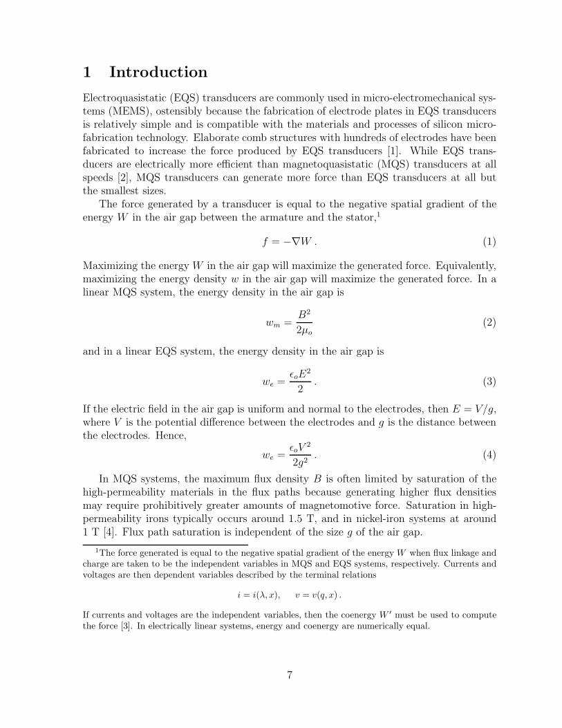
Figure 3: The macroscale magnetically-levitate planar actuator that was im-plemented in [9]. Four wire-wound stators and four facing perma-nent magnet armatures formed two motors in x and z and twomotors in y and z.
was developed where the fabrication of polyphase windings using conventional wire wouldbe very difficult. At the same time, the size of the actuator was kept large enough thathigh-energy sintered permanent magnet materials could be magnetized first and thenassembled into the actuator without undue difficulty. The throw range of the actuatorwas chosen to be well beyond the throw range of piezoelectric stacks.
Numerous mesoscale linear magnetic actuator concepts, both original and in the lit-erature, were considered where the windings might be fabricated using MEMS processes.The macroscale, magnetically-levitated, planar actuator in [9] was identified as beingparticularly well suited for miniaturization using MEMS-fabricated windings due to itsmechanical simplicity and precision requirements. This macroscale actuator is shown inFigure 3. A platen containing four permanent magnet armatures is magnetically levitatedover four planar stators. The four motors both levitate and propel the platen laterallyin two dimensions. The design contains no high-permeability materials that might causeproblematic trapping and cogging forces. As such, the actuator is optimized for high
10

precision rather than high force. The magnetic bearing conveniently avoids the frictionproblems that arise in MEMS devices but at the expense of higher power dissipation inthe stator windings.
The high-performance operation of this actuator depends partly on the smoothnessof the surface of the stator windings. Achieving a smooth stator surface becomes moredifficult as the overall size of the actuator is reduced.3 A very smooth surface can beachieved if the stator windings are fabricated on a wafer using a lithographic process.Other benefits of a lithographic approach for this actuator include very accurate coilgeometry definition, very accurate relative positioning of the stators, and the ability tobatch fabricate the stators. If lithographically-fabricated stators could be made that havea high enough current-handling capability (possibly using a multi-layer LIGA process), alithographic approach could even be used to fabricate the stators for macroscale actuatorssuch as the one in [9]. A finding of the present study is that lithographically-fabricatedstators appear to support significantly higher current densities than conventionally woundstators.
For the present study, a multilayer planar polyphase coil architecture was developedthat can be fabricated with any number of lithographic MEMS processes. The architec-ture is based on split-level spiral coils that are uniquely suited for implementing windings
in planar linear actuators. To demonstrate the new coil architecture, a prototypeactuator approximately one-fifth the size of the actuator in [9] was fabricated using alithographic high-density interconnect (HDI) process.
2 Literature Review
Considerable progress has been made increasing the force output of MEMS EQS trans-ducers (see [1], for example). Progress implementing MEMS MQS transducers, on theother hand, has been more modest. The primary reasons for this are (a) the difficulty ofimplementing coil structures, (b) the need for high-permeability materials not typicallyfound in integrated circuit fabrication processes, and (c) the difficulty of magnetizinghigh-energy permanent magnet materials in-place. The last issue has prevented the de-velopment of micron-scale transducers with high-energy permanent magnets. MEMSactuators utilizing high-energy permanent magnets have been millimeter-scale devices.
Early efforts to produce MEMS MQS transducers focused on variable-reluctancetransducers where the coils were external to the structure of the actuator and were woundwith conventional wire [10]. With such devices, it was learned how to micro-fabricate thehigh-permeability materials required for variable-reluctance transducers.
Fabricating high-permeability materials in-place is also of interest for fabricatingMEMS inductors. The coil topologies required for inductors are relatively simple and
3Fabrication of a prototype stator, identical to the actuator in [9] but approximately one-fifth the size,was attempted using individual coils wound with 43 gauge wire. A commercial vendor that specializes inwinding microcoils tried numerous time without success to wind coils that when assembled into a statorcreated a smooth stator surface.
11
progress has been made in lithographically fabricating inductor coils with high-permeabilitycores. The simplest lithographically-fabricated coil topology is a spiral on a single layerand a variety of implementations have been reported. Single-layer planar spiral coilswere stacked in [11] and [12] to form inductors. An actuator was formed from an arrayof lithographically-fabricated single-layer spiral coils in [13]. The array of coils faced anarray of small permanent magnets glued to the backside of a deformable mirror. A sim-ilar array of single-layer spiral coils was fabricated in [14] to attract and repel a facingrigid planar array of magnets.
Implementations of single-layer planar coils for rotary magnetic actuators are reportedin [15] and [16]. In [15], two layers of spiral coils for an axial flux rotary actuator wereazimuthally offset from each other on either side of a supporting foil. The rotor, approx-imately 12 mm in diameter, was made my injection molding bonded magnet material.In [16], six layers of spiral coils were built up lithographically, with each layer offset az-imuthally. Rotors, 1.6 mm and 1.9 mm in diameter, for the axial flux motor in [16] werecut from bulk sintered high-energy permanent magnet material using electro-dischargemachining. Up to twelve poles were then magnetized on the rotors. Impressive magneticremanences of approximately 0.8 T were achieved.
More sophisticated fabrication efforts have attempted to spread coils across multiplelayers. In [17], a conductor was spiraled around high-permeability material such that themagnetization vector of the coil was parallel to the fabrication plane. The goal was coilsthat drive flux through in-plane variable reluctance actuators, and hence represents thenext evolutionary step from the earlier work in [10].
The coil architecture closest to the present study is reported in [18]. In [18], the statorcoils for an axial flux rotary motor were fabricated across two layers such that each statorphase formed a continuous helix around the azimuthal axis of the stator. The conductorsof each stator phase traveled continuously around the stator, contributing to each polepitch in the phase. This seemingly innocuous change from single-layer spiral coils, asin [15] and [16], to continuous helical coils is significant in that the packing factor of thecontinuous split-level helical winding is much greater.
The architecture in [18] is unique to rotary machines and not suitable for linearmachines. In a rotary machine, the conductors within a phase can travel continuouslyaround the stator, contributing to each pole pitch. In a linear machine, the stator doesnot begin and end at the same place and hence each pole pitch in a phase needs to beself-contained in order to avoid numerous return conductors traveling from the end ofthe stator back to the beginning, as would be the case if the winding structure in [18]were used for a linear machine. In other words, spiral coils are needed like those in [15]and [16]. The problem with the single-layer spiral coils in [15] and [16] is that it is notpossible to implement more than one phase per layer because the sides and end-turns ofeach coil form a closed polygon in the layer, excluding access to the middle of the coil.
The coil architecture in the present study yields a stator suitable for linear machines,but with a high packing factor as in [18]. Spiral coils are split across two layers: onehalf of a coil on an upper layer and the other half of the coil on a lower layer. Split-level
12
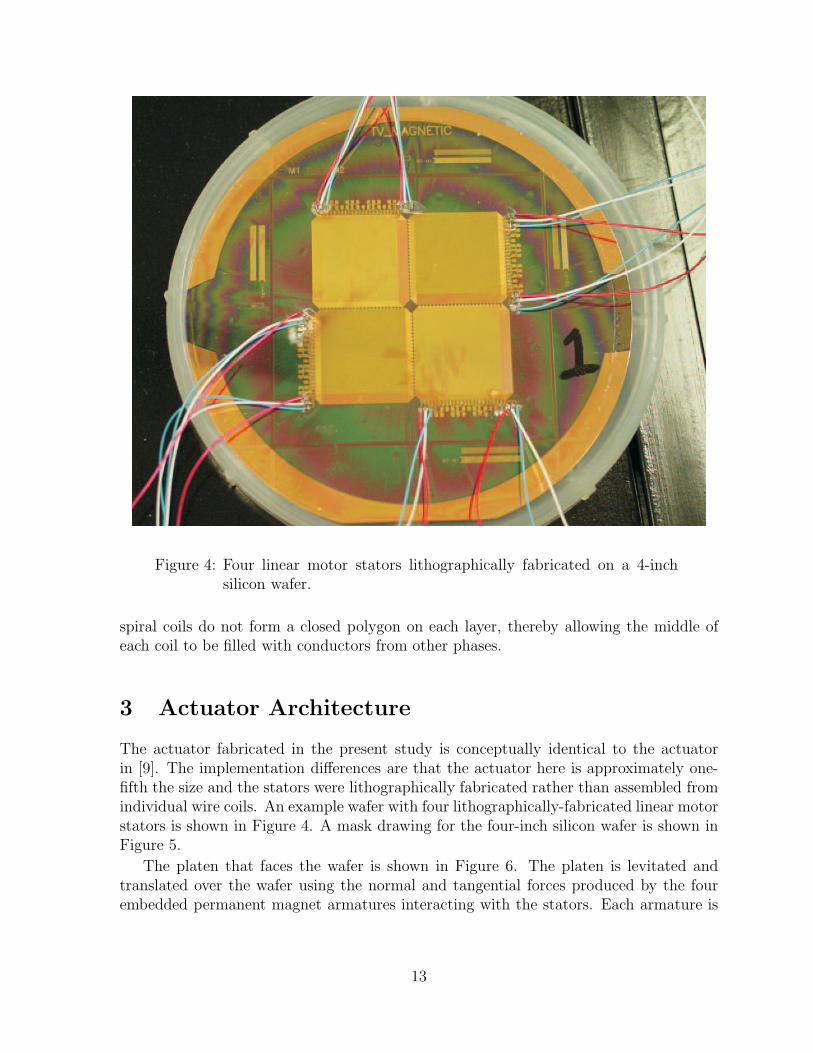
Figure 4: Four linear motor stators lithographically fabricated on a 4-inchsilicon wafer.
spiral coils do not form a closed polygon on each layer, thereby allowing the middle ofeach coil to be filled with conductors from other phases.
3 Actuator Architecture
The actuator fabricated in the present study is conceptually identical to the actuatorin [9]. The implementation differences are that the actuator here is approximately one-fifth the size and the stators were lithographically fabricated rather than assembled fromindividual wire coils. An example wafer with four lithographically-fabricated linear motorstators is shown in Figure 4. A mask drawing for the four-inch silicon wafer is shown inFigure 5.
The platen that faces the wafer is shown in Figure 6. The platen is levitated andtranslated over the wafer using the normal and tangential forces produced by the fourembedded permanent magnet armatures interacting with the stators. Each armature is
13

Figure 5: Wafer mask drawing with the four motor stators indicated. Mo-tors 1 and 3 actuate in x and z (out of the page), while motors 2and 4 actuate in y and z.
14

Figure 6: Platen surface facing the wafer. Four permanent magnet armaturesare embedded in the platen surface facing the stators. Each arma-ture is a nine-magnet Halbach array.
a nine-magnet Halbach array. The Halbach arrays exhibit at enhanced magnetic field onthe side facing the stator windings and a reduced magnetic field on the away side. Theplaten and its magnet arrays are discussed further in Appendix B.
The platen and wafer are shown together in Figure 7. When the motors are operating,the platen is levitated and moved laterally over the wafer by the four motors. Closed-loop servoing of the platen is necessary because the lateral dynamic modes are unstable.Six laser displacement sensors are used to provide position feedback. The peak-to-peakthrow of the actuator is 6 mm in both x and y.
Motors 1 and 3 in Figure 5 are oriented so that they can produce z-directed normalforces (out of the page) and x-directed tangential forces. Motors 2 and 4 are oriented sothat they can produce z-directed normal forces and y-directed tangential forces. Figure 5shows that Motor 3 is a mirror image of Motor 1 and Motor 4 is a mirror image of Motor2.
As previously stated, the general topology of four motors levitating and translating
15
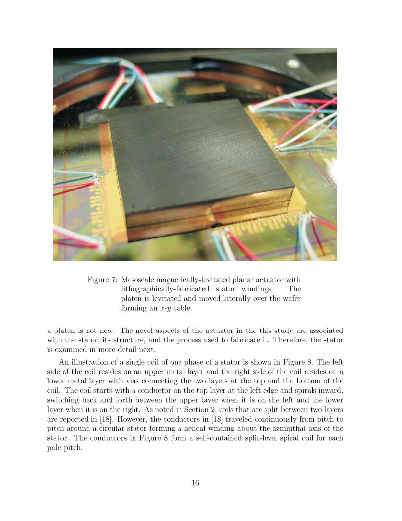
Figure 7: Mesoscale magnetically-levitated planar actuator withlithographically-fabricated stator windings. Theplaten is levitated and moved laterally over the waferforming an x-y table.
a platen is not new. The novel aspects of the actuator in the this study are associatedwith the stator, its structure, and the process used to fabricate it. Therefore, the statoris examined in more detail next.
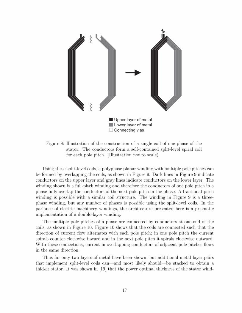
An illustration of a single coil of one phase of a stator is shown in Figure 8. The leftside of the coil resides on an upper metal layer and the right side of the coil resides on alower metal layer with vias connecting the two layers at the top and the bottom of thecoil. The coil starts with a conductor on the top layer at the left edge and spirals inward,switching back and forth between the upper layer when it is on the left and the lowerlayer when it is on the right. As noted in Section 2, coils that are split between two layersare reported in [18]. However, the conductors in [18] traveled continuously from pitch topitch around a circular stator forming a helical winding about the azimuthal axis of thestator. The conductors in Figure 8 form a self-contained split-level spiral coil for eachpole pitch.
16
Upper layer of metal
Lower layer of metal
Connecting vias
Figure 8: Illustration of the construction of a single coil of one phase of thestator. The conductors form a self-contained split-level spiral coilfor each pole pitch. (Illustration not to scale).
Using these split-level coils, a polyphase planar winding with multiple pole pitches canbe formed by overlapping the coils, as shown in Figure 9. Dark lines in Figure 9 indicateconductors on the upper layer and gray lines indicate conductors on the lower layer. Thewinding shown is a full-pitch winding and therefore the conductors of one pole pitch in aphase fully overlap the conductors of the next pole pitch in the phase. A fractional-pitchwinding is possible with a similar coil structure. The winding in Figure 9 is a three-phase winding, but any number of phases is possible using the split-level coils. In theparlance of electric machinery windings, the architecture presented here is a prismaticimplementation of a double-layer winding.
The multiple pole pitches of a phase are connected by conductors at one end of thecoils, as shown in Figure 10. Figure 10 shows that the coils are connected such that thedirection of current flow alternates with each pole pitch; in one pole pitch the currentspirals counter-clockwise inward and in the next pole pitch it spirals clockwise outward.With these connections, current in overlapping conductors of adjacent pole pitches flowsin the same direction.
Thus far only two layers of metal have been shown, but additional metal layer pairsthat implement split-level coils can—and most likely should—be stacked to obtain athicker stator. It was shown in [19] that the power optimal thickness of the stator wind-
17

A A A A A A A AC C C C C C C CB B B B B B B B
Upper layer of metal Lower layer of metal
Figure 9: Polyphase planar winding formed by overlapping the split-level coilsillustrated in Figure 8.
18

Upper layer of metal Lower layer of metal
Figure 10: Double-layer polyphase planar winding with pole-pitch connectionson one end. Pads for each pitch of each phase were brought outfor testing purposes. The last set of pads on the far right can beconnected together to form a three-phase Y connection.
19

Metal Layer Pair 1 Metal Layer Pair 2 Metal Layer Pair 3
Current
Figure 11: Current flow in multiple layer-pair stators. Metal layer pairs canbe stacked to realize thicker stators. The current flow pattern il-lustrated allows each metal layer pair to be fabricated and testedbefore continuing with the fabrication of the next metal layer pair.
ings in a synchronous machine with Halbach arrays is one-fifth the fundamental spatialperiod of the magnetic field in the machine. The flow of current through multiple layerpairs is illustrated in Figure 11 for a six-layer stator. The particular current flow patternshown was chosen to ease fabrication in that each metal layer pair can be fabricated andtested before continuing with the fabrication of the next metal layer pair.
4 Fabrication Process
The split-level spiral coil architecture described in Section 3 can support any numberof phases, any amount of pitch overlap, and any number of turns in the pole pitches.The cross-section of the individual conductors in the coils, however, depends on therequirements of the application and the lithographic process used to fabricate the coils.Generally speaking, multiple turns in a stator coil are used to enforce a required currentdensity throughout the volume of the coil. Multiple turns also increase the resistanceof the coil, which makes it easier to control the current in the coil, albeit with greaterpower dissipation. The cross-section of each conductor and the number turns per coil ischosen to satisfy these (and possibly other) requirements.
The lithographic processes that might be used to fabricate multiple layers of patternedconductors and dielectric for the high-current stators in mesoscale actuators can be bro-ken into two classes: lapped processes and non-lapped processes. In lapped processes,the dielectric layers used to construct a planar coil must be mechanically replanarizedbefore continuing with the next layer of metal. An advantage of these processes is thateach metal layer can be very thick, for example up to several hundred microns with LIGAprocesses. Thick metal patterns will create undulations in the next dielectric layer, mak-ing it non-planar. The dielectric layer is therefore planarized by mechanical lapping. Theapplication of lapped processes is reported in [15, 16, 11, 18, 17].
In non-lapped processes, a liquid polymer dielectric is deposited on a metal pattern.The liquid polymer flows on the wafer surface and planarizes the undulations due to metalpattern before the polymer is cured. The self-replanarization of the liquid polymers is
20
not as complete as with mechanical lapping and hence the thickness of the metal layers islimited to several tens of microns. Nevertheless, the elimination of lapping substantiallyreduces the number of costly processing steps. The application of a non-lapped processis reported in [12]. A non-lapped process similar to that reported in [12] was used in thepresent study to fabricate the stator coils described in Section 3.
The benzocyclobutene/copper (BCB/Cu) high-density interconnect (HDI) processwas used to fabricate the stators. The dielectric benzocyclobutene is a Dow ChemicalCompany trade mark product from the cyclotene family. The detailed properties of thisfamily of polymers may be found at www.cyclotene.com. A 5 µm thick photoimageableBCB (Dow Product No. 4024-40) was used.
N-type silicon wafers, 100 mm in diameter with a 2400 A thick silicon dioxide layerdeposited on the surface, were used as substrates. The surface roughness was 1.5 nmas measured by the root-mean-square of bump height obtained with an atomic forcemicroscope (AFM). The conductor metals used were evaporated 200 A titanium and3 µm copper.
The wafers were cleaned and the first layer of conductor was deposited and photo-patterned. This layer was followed by a 5 µ thick layer of liquid BCB, deposited by spincoating. Vias and streets in the BCB were then photo-patterned. After partially curingthe BCB at 210C, the second layer of conductor lines was photo-patterned. Finally,BCB was fully (hard) cured at 250C. A detailed process for BCB may be found at thecyclotene Web site.
Because the BCB/Cu process was newly implemented at Sandia when the fabricationwork for this study was performed, the metals were evaporated onto the wafer, ratherthan electroplated. As a result, the thickness of the metal layers was limited to 3 µm.The next generation of circuits using 15 µm thick copper deposited by electroplating iscurrently being investigated.
5 Results
The BCB/Cu HDI process was used to fabricate four stators simultaneously on four-inchwafers, as shown in Figures 4 and 5. To ensure high yield, only two layers of metal andone intervening layer of BCB were fabricated—enough to fabricate three-phase statorscomposed of split-level spiral coils. Dimensions of the individual conductors in the coilsare shown in Figure 12. These dimensions are coincidentally almost identical to theconductor cross-section dimensions in [13]. As discussed in the previous section, the pro-totype stators were fabricated with evaporated metal, and therefore the thickness of theconductors was limited to 3 µm, which was verified by cross-section measurements. Fromthe mask drawings, the phase resistance was calculated to be 88 Ω. The average phaseresistance of the two motors (six measurements) used in the levitation tests describedbelow was 88 Ω.
Tests were performed to determine the current-carrying capacity of the stators. Thesurface of a partially defective wafer was painted black and the wafer was mounted on a
21

Figure 12: Conductor dimensions in the prototype actuator stator shown inmillimeters. The gap between conductors is the minimum that canbe achieved with the BCB/Cu HDI process at Sandia. Currentdensity is maximum in the end turns where the conductors narrow(while maintaining the minimum gap).
block of aluminum on an infrared (IR) camera x-y stage using thermal grease. The IRcamera was used to monitor the temperature of the stators while an increasing amountof power was applied to a phase of a stator. Power was applied until thermal steady-statewas achieved. After each test, the wafer was allowed to cool and the phase resistanceswere verified to be unchanged from the beginning of the test.
Testing stopped when the limits of the power supply being used were reached. Inthe final test, 1.06 A flowed through one pole pitch of a phase and the peak steady-statetemperature of the pole pitch was observed to be 107C. The stator was undamaged bythe test. At this peak current level, the current density in the end turns of the winding(the part of the winding with the smallest cross-section) was 4.2×10⁹A/m2. This currentdensity is equivalent to flowing 213 A through a strand of 30 gauge wire. For reference,30 gauge wire is rated at 0.8 A for a single wire in free air and 0.5 A for a bundle of wires.It may be that the intimate contact of the stator conductors with the silicon wafer (lowermetal layer) and the BCB (upper metal layer) permits steady-state current densities
22

approximately two orders of magnitude greater than can be achieved with conventionalwire. Similar results were obtained in [18].
Levitation tests were conducted to determine the current required to statically levitatethe platen. A platen was levitated over the stators using two of the four stators (motors 2and 4 in Figure 5). Motions in x and y were constrained. Servo loops were closed inthe z direction using laser displacement sensors. The average direct current per motorrequired to levitate the platen 100 µm above the stator was measured to be iD = 138 mA,which corresponds to three-phase currents of iA = −56.3 mA, iB = −56.3 mA, andiC = 112.5 mA. (See Appendix H for details on computing three-phase currents from DQcurrents.) The current required to statically levitate the platen is an order of magnitudebelow the maximum steady-state current the stator is capable of carrying.
The force model in [9] was used to calculate the current required to levitate the platen.When parameters for the actuator in the present study are used, the model predicts adirect current iD of 96 mA. At first glance, the model (96 mA) and the experiment(138 mA) do not appear to be in good agreement. However, if the air gap is doubledto 200 µm, the model predicts a 114% increase in the direct current to iD = 109 mA.The experimentally measured increase was 115%. This observation suggests that directaxes of platen magnet arrays were not properly aligned over the stator and that someof the measured direct current was, in fact, quadrature current. The normalized forceproduction predicted by the model is 0.54 N/A, which is low because of the thinnessof the stator windings. (Recall that only one metal layer pair was implemented in theprototype.) For thin stators, force production increases approximately linearly with thethickness of the windings. Therefore, a six-layer stator fabricated using electroplatingwith six 15 µm thick metal layers would produce approximately 8.8 N/A. Details of themodel calculation may be found in Appendix D. Additional experimental results may befound in Appendix I.
6 Conclusions
The contribution of the this study is a planar multilayer polyphase coil architecturethat provides for the lithographic implementation of efficient stator windings suitablefor linear electric machines. A linear actuator was identified that can benefit from theprecise lithographic fabrication of its stator windings in mesoscale implementations andpossibly even in macroscale implementations. A mesoscale prototype was implementedusing lithographically-fabricated stator windings.
The stator windings in the prototype actuator were implemented using a non-lappedBCB/Cu HDI process. Relative to lapped processes, this process is simple and inex-pensive. The prototype stator was limited to thin copper layers (3 µm) due to the useof evaporated metal at the time of fabrication. More recently, investigations using elec-troplated metal have shown that BCB adequately replanarizes for metal traces up to15 µm.
Tests showed that the stator windings are capable of handling very high current
23

densities (approximately 4 × 10⁹A/m2), providing sufficient current capacity for bothlevitation and translation. Levitation tests revealed force production that scales well tostators lithographically fabricated with thicker copper layers.
7 Future Work
Outstanding issues that need to be addressed include (a) the development of lithographicprocesses that yield substantially thicker metal layers and (b) a miniaturized feedbackmechanism for commutating the motors and controlling the platen.
As discussed in previous sections, the BCB/Cu HDI process is a relatively simpleprocess for fabricating traces of metal. It is currently being developed at Sandia forthe interconnection of low-power, high-frequency circuitry. In addition to being self-replanarizing, BCB has excellent dielectric properties and low moisture uptake during andafter processing. Development of the process has been focused on fabricating traces withwell-defined impedances and on embedding passive components [20, 21]. More recently,customers funding development of the process have requested greater power-handlingcapability, and hence electroplating of the metal layers is currently being investigated [22].This new process would greatly improve the performance of stators in magnetic actuators;force production would increase and power dissipation in the stator would decrease.
It is likely, however, that other processes will prove in the long run to be more suitablefor the fabrication of magnetic actuator windings. Two processes stand out. First is amulti-layer LIGA process. For each layer the mold PMMA would need be removed andreplaced with an electrical insulator with better thermal stability and higher thermalconductivity. After replanarization, a new layer of PMMA would be applied and theprocess repeated. Significant process development work would be necessary before astator could be implemented in this way.
The second process that holds promise is based on SU-8. SU-8 is negative UV resistthat allows the realization of high aspect ratio structures (though not has high as LIGA).With SU-8, conductors with a high aspect ratio cross-section could be fabricated usingrelatively standard lithography equipment (unlike LIGA). SU-8 was used to fabricatesingle-plane coils with conductors 12 µm wide and 64 µm thick in [15]. Consider thatif the stators in the present study were implemented with conductors 64 µm thick (by140 µm wide), a six metal layer stator would yield an astounding force production ratioof approximately 38 N/A and an excellent phase resistance of approximately 11 Ω. Theproblem with SU-8 is that it has a very poor thermal conductivity of 0.2 W/m-K (asdoes BCB and PMMA) and removing the irradiated SU-8 and replacing it with a highthermal conductivity electrical insulator is difficult because irradiated SU-8 is impervi-ous to virtually all solvents [23]. As with the LIGA process above, significant processdevelopment work would be necessary before a stator could be fabricated using SU-8.
The other outstanding issue is development of a miniaturized feedback mechanism forcommutating the motors and servoing the platen. Sensing the vertical displacement ofthe platen from the stator might be performed using capacitive sensors embedded in the
24

stator. The sensor interface circuitry could be embedded directly into the BCB layers.The work already performed on embedding passive components in the BCB layers pointsin this direction.
More challenging is sensing the lateral displacements of the platen. One idea is tomount Hall-effect sensors in the center space between the four motors (see Figure 5)that sense a small magnet array mounted at the center of the platen. Another idea isto implement miniature laser displacement sensors around the periphery of the actuatorto measure the displacement away from each sensor, possibly using VCSELs. A thirdidea is mount optical structures on top surface of the platen through which lateral laserbeams and detectors measure the displacement of the platen over the stator.
Finally, further development of MEMS magnetic actuators is contingent on finding acompelling application where a customer is willing to fund the additional developmentefforts described above. It is hoped that by pushing the size of the actuator into themesoscale realm more application opportunities will arise.
25

A Actuator Parameters
Parameters for the actuator in this study are compiled here for reference.
• Nominal actuator throw = ±3 mm in x and y.
• Nominal air gap zo = 100 µm.
• Machine pole-pair pitch l = 4.8 mm.
• Machine fundamental wave number γ1 = 1309 m−1.
• Magnet array thickness ∆ = 1.2 mm.
• Magnet array width w = 12 mm.
• Number of magnet array pole-pair pitches Nm = 2.
• Magnet remanence (each magnet in the array) Br = 1.21 T.
• Total mass of the platen (including 4 magnet arrays) = 10.59 g.
• Average mass of a glued magnet array = 1.225 g.
• Average mass of the magnets in an array = 1.213 g.
• Average mass of the glue in an array = 0.012 g.
• Number of stator phases = 3.
• Number of stator pole-pair pitches = 4.
• Stator winding thickness Γ = 9.3 µm.
• Stator winding pitch factor kp = 1 (full pitch).
• Number of stator turns per pitch = 5.
• Stator conductor thickness (nominal) = 3 µm.
• Stator conductor pitch (coil center) = 160 µm.
• Stator conductor width (coil center) = 140 µm.
• Stator conductor-to-conductor gap (coil center) = 20 µm.
26
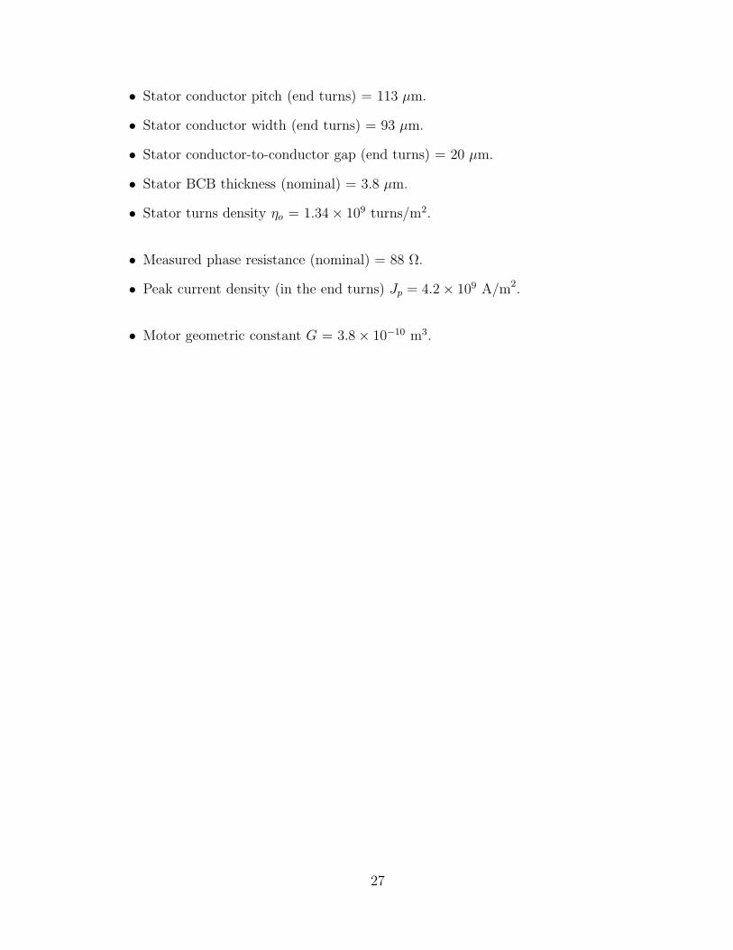
• Stator conductor pitch (end turns) = 113 µm.
• Stator conductor width (end turns) = 93 µm.
• Stator conductor-to-conductor gap (end turns) = 20 µm.
• Stator BCB thickness (nominal) = 3.8 µm.
• Stator turns density ηo = 1.34 × 10⁹ turns/m2.
• Measured phase resistance (nominal) = 88 Ω.
• Peak current density (in the end turns) Jp = 4.2 × 10⁹ A/m2.
• Motor geometric constant G = 3.8 × 10⁻¹⁰ m3.
27

B Platen
The platen carries the actuator payload. Optimally, payloads would be passive and thusnot require an umbilical cord, which might disturb the dynamics of the platen. In thisstudy, the only payload carried by the platen was an aluminum cover plate.
A photograph of the surface of the platen that faces the wafer is shown in Figure 13.The four magnet arrays can be clearly seen that match the four stators on the wafer. Afabrication drawing for the magnet arrays is shown in Figure 14. The depth of the arrayis 12 mm. The cross-section dimensions of the inner magnets are 1.2 mm by 1.2 mm. Thecross-section dimensions of the end magnets are 1.2 mm by 1.45 mm. The lengtheningof the end magnets is to compensate for the truncation of the array and to improve thefundamental magnetization harmonic of the array. The separation features indicated onthe drawing are a vestige of the manufacturing process and were used to keep track ofthe different types of magnets (A, B, and C) prior to magnetization.
The magnets in the array are made of sintered neodymium iron boron (Nd2Fe14B,
Figure 13: Four Halbach magnet arrays mounted in the platen.
28

Figure 14: Halbach magnet array fabrication drawing.
or NdFeB for short). Bulk slabs of the material were purchased from the manufacturer4
precision ground to 12 mm with the preferred direction of magnetization parallel to thegrinding plane. The micro-EDM machine in division 14000 was used to cut 12 mm longmagnets with multiple clockwise and counter-clockwise EDM passes until the desiredtolerances were achieved, at which point a final cut was made to release the magnet fromthe slab. The imprecision of the final cut is evident in a visible separation mark that wasused to identify the magnet type. Type A magnets were easy to identify by their non-square cross sections and they were cut from the bulk slab with the preferred directionof magnetization parallel to the surface with the separation mark. Type B magnets werecut from the bulk slab with the preferred direction of magnetization normal to the surfacewith the separation mark. Lastly, Type C magnets were cut from the bulk slab with thepreferred direction of magnetization parallel to the surface with the separation mark,similar to the Type A magnets. Type B and Type C magnets were differentiated by theposition of the separation mark, as shown in Figure 14. The separation mark on Type Bmagnets was centered on the magnet, while the separation mark on Type C magnets wasoffset.
4Magnetic Component Engineering, 2830 Lomita Blvd., Torrance CA 90505,http://www.mceproducts.com.
29

An LDJ 6607-1 magnetizer was used to magnetize the magnets.5 The magnetizer wasoperated at its maximum pulse energy (7500 J) to ensure complete magnetization of theparts. A pole sensor was used to verify the correct magnetization of each part.
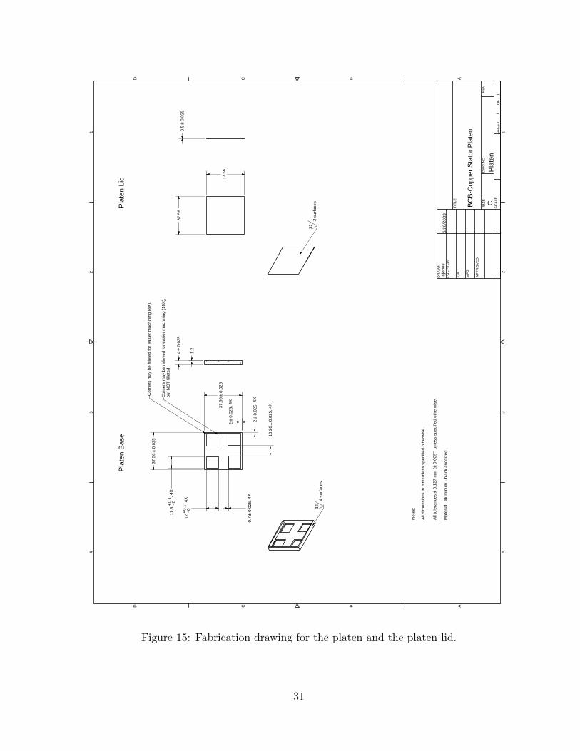
After magnetization, the individual magnets were assembled in-place in the windowsof the platen shown in Figure 15. Assembly was facilitated by the use of a Teflon-coatedsteel backing plate on the stator side of the array. The backing plate served to hold thearray in approximate position prior to gluing and clamping. Loctite 294 threadlockerwas used to bond the array, since it is activated by iron, which is present in the NdFeBmagnets. It was found that Loctite 294 adequately held the bonded arrays in the windowsof the aluminum platen and thus a subsequent layer of epoxy to bond the arrays to platenwas not applied.
Sintered neodymium iron boron is available in the highest energy products of allpermanent magnet materials. Its chief competitor is samarium cobalt, which is availableat slightly lower energy products, but with lower temperature coefficients and greaterresistance to corrosion. Neither temperature nor corrosion were a concern for the actuatorin the present study and so neodymium iron boron was the natural choice. It shouldalso be noted that samarium cobalt is substantially more expensive than neodymiumiron boron since cobalt is a strategic material, but due to the small volume of materialrequired for the actuator in this study, cost was not a driver.
The specific magnet material used was N3578, which has a maximum energy productof 35 MG-Oe and a nominal remanence Br at 20C of 1.21 T. The nominal intrinsiccoercivity Hci of the material is 29 kOe. Choosing a material with a high intrinsiccoercivity was important as the corners of the magnets in a Halbach array experiencedemagnetization (as will be discussed below). A material with a slightly higher energyproduct could have been chosen (around 40 MG-Oe), but as the energy product goes up,the intrinsic coercivity decreases, thereby increasing the risk of localized demagnetizationin the magnet array.
The magnetization pattern shown in Figure 14 is known as a Halbach array. Moreprecisely, it is a discrete Halbach array in that the magnetization vector of the array isrotated in 90 increments. In a continuous Halbach array, the magnetization vector isuniformly rotated in the array and the fundamental harmonic of the magnetic field on oneside of the array is completely cancelled. The fundamental harmonic on the other sideis enhanced by π/2 relative to a conventional array with the same pole pitch and wherethe magnetization vector is rotated in 180 increments [19]. The discrete Halbach arrayin Figure 14 is an approximation of a continuous Halbach array that is relatively easy tofabricate. In the discrete array the fundamental harmonic of the magnetic field on oneside (the side away from the stator) is still completely eliminated and the fundamentalon the other side (the side facing the stator) is enhanced to almost the same degree asa continuous Halbach array, namely
√2. Halbach arrays were first reported in 1980 by
Klaus Halbach [24] for beam shaping in particle accelerators. The usefulness of Halbacharrays in electric machines was not identified until more than a decade later by Trumper
5Walker LDJ Scientific, Rockdale Street, Worcester, MA 01606, http://www.walkerldj.com.
30
1 1
2 2
3 3
4 4
AA
BB
CC
DD
TITL
E
SIZE
DW
G N
OR
EV
SCAL
ESH
EET
OF
DR
AWN
CH
ECKE
D
QA
MFG
APPR
OVE
D
BCB-
Cop
per S
tato
r Pla
ten
Plat
en1
1C
lajo
nes
6/26
/200
3
Plat
en L
idPl
aten
Bas
e
Not
es:
All
dim
ensi
ons
in m
m u
nles
s sp
ecifi
ed o
ther
wis
e.
All t
oler
ance
s 0.
127
mm
(0.
005"
) unl
ess
spec
ified
oth
erw
ise.
Mat
eria
l: a
lum
inum
- bl
ack
anod
ized
.
11.3
- 00.1
+, 4
X
12- 00.
1+
, 4X
0.7
0.02
5, 4
X
10.2
60.
025,
4X37
.56
0.02
5
37.5
60.
025
40.
025
1.2
37.5
6
37.5
6
0.5
0.02
5
3232
4 su
rface
s2
surfa
ces
20.
025,
4X
20.
025,
4X
Cor
ners
may
be
relie
ved
for e
asie
r mac
hini
ng (1
6X),
but N
OT
fille
ted.
Cor
ners
may
be
fille
ted
for e
asie
r mac
hini
ng (4
X).
Figure 15: Fabrication drawing for the platen and the platen lid.
31

Figure 16: Finite element computation of the flux density of the Halbach mag-net array in Figure 14.
in [19].6
The magnetic field produced by the array in Figure 14 was computed using Maxwell 3Dby Ansoft.7 A cross-section of the magnetic field down the middle of the array is shownin Figure 16 where it can be seen that the magnetic field is confined to one side of thearray.
6It should be noted that Halbach arrays were applied to electric machines with no high-permeabilitymaterials in [19]. It has since been determined that conventional magnet arrays are superior whenhigh-permeability materials are used to guide flux in the machine [25, 26]. The primary application ofHalbach arrays in electric machines has been for linear machines that use integrated magnetic bearings,such as the actuator in the present study and, interestingly, magnetically-levitated trains [27].
7Ansoft Corporation, Four Station Square, Suite 200, Pittsburgh, PA 15219-1119,http://www.ansoft.com.
32

C Wafer Design
The planar windings were lithographically fabricated on four-inch silicon wafers in theCSRL. The complete design included six layers of metal and five intervening layers ofBCB. Masks for the six metal layers are shown in Figures 17 through 22. The masks forthe five intervening layers of BCB are not shown as they largely consist of vias betweenthe metal layers.
Due to yield problems, only the first two layers of metal, with a single interveninglayer of BCB were fabricated. Photographs of a wafer immediately after processing areshown in Figure 23. The active circuit area is approximately 6 cm2 with 140 µm traceson a 160 µm pitch (20 µm line-to-line spacing) throughout.
Even after stopping at two metal layers, a wafer with four fully functional stators wasnot successfully fabricated. One wafer was completed with three fully functional statorsand several wafers were completed with two fully functional stators. In the latter set,only two wafers had functional stators that were diagonal from each other (that is, eithermotors 1 and 3 or 2 and 4).
The failure modes observed in the stators were electrically open phases, abnormallyhigh or low phase resistances, and phase-to-phase shorts. The source of these problemswas often found to be contamination of the wafers by large dirt particles, rather thanproblems with the BCB process itself. Dirt particles ranging in size from tens of mi-crons to hundreds of microns were found on the wafers. The dirt particles would eitherblock the evaporated metal (open phases and high-resistance phases) or provide a bridgeacross traces during metal deposition (low-resistance phases and phase-to-phase shorts).As more experience was gained, cleanliness procedures were implemented that reducedthe contamination problems. The situation will greatly improve when the new MESAfacilities come on line. Examples of other wafer defects are shown in Figure 24.
Other fabrication lessons were learned with respect to the wafer designs. First, largersoldering pads should be used. Larger pads were included on metal layer six, but on thelower layers, 0402 surface-mount pads were used. While soldering 0402 surface-mountcomponents is not difficult, soldering 30 gauge wires to 0402 pads proved to be muchmore difficult. Two wafers were lost to soldering problems caused by the pads on thelower layers being too small.
The second lesson is the importance of a final passivation layer. During normal oper-ation of the actuator, a passivation layer was not necessary because of oxide layers thatnaturally form over both the stator conductors and the armature magnets. These oxidelayers prevent the magnets from electrically shorting the windings. (Due to their ironcontent, NdFeB magnets have a moderate conductivity of approximately 144 µΩ-cm—about the same as mercury.) During operation, however, control system upsets maycause the armature to impact the stator and break through these oxide layers. Such afailure was experienced and is described in Appendix I.
33

Figure 17: Mask for metal layer 1.
34

Figure 18: Mask for metal layer 2.
35

Figure 19: Mask for metal layer 3.
36

Figure 20: Mask for metal layer 4.
37

Figure 21: Mask for metal layer 5.
38
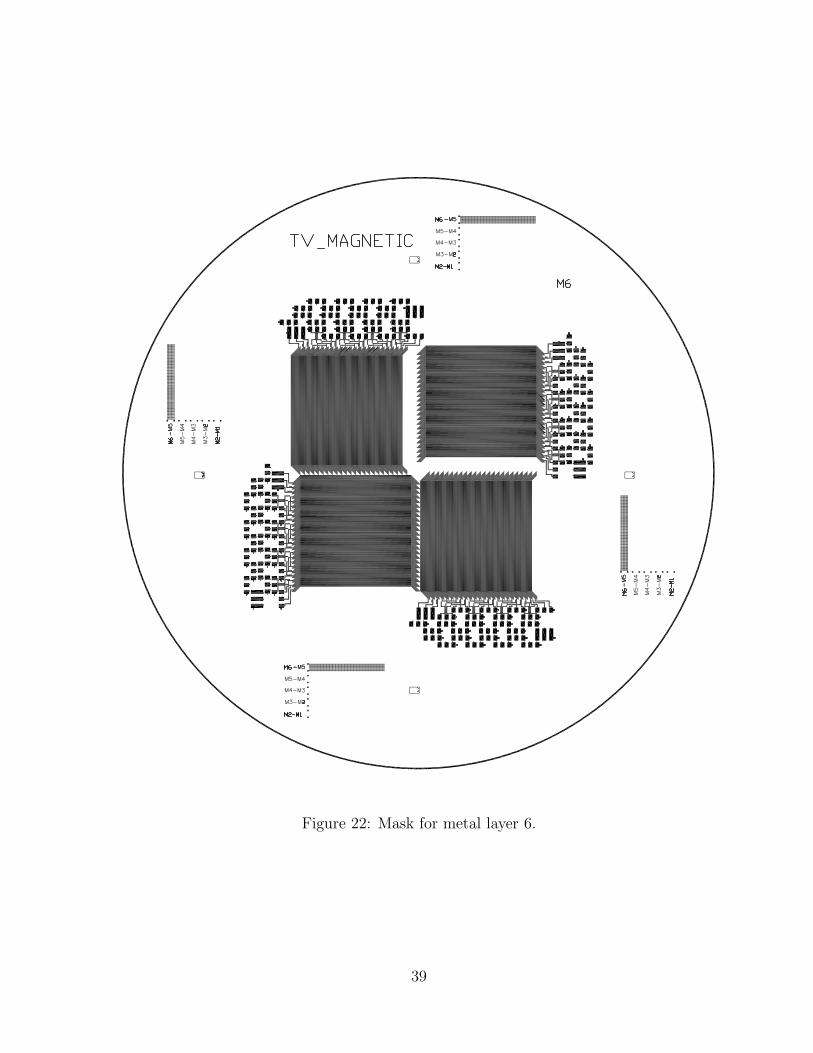
Figure 22: Mask for metal layer 6.
39

(a) (b)
Figure 23: (a) Wafer after processing the first two layers of metal with one in-tervening layer of BCB. (b) Magnified view showing the high densityof the stator conductors.
Figure 24: Examples of defects observed on the wafers.
40

D Force Modeling
The currents flowing through the stators in Figure 7, interact with the facing Halbachmagnet arrays to generate Lorenz forces. In electric machine theory, the stator currentsare typically decomposed into a current that generates force normal to the stator surfaceand a current that generates force tangent to the stator surface. These currents are knownas the direct current and the quadrature current, respectively. In a rotary motor, directcurrents act only to the compress the rotor about its axis and hence are undesirable.8
High-performance rotary motor drives typically generate stator currents that have onlya quadrature component.
In the levitated planar actuator of the present study, direct currents (iD), whichgenerate normal forces (fn), are used to levitate the platen, and quadrature currents (iQ),which generate tangential forces (ft), are used to propel the platen laterally. Expressionsrelating these forces and currents are (adapted from [9])9
[fn
ft
]=
1
2BrηoNmGe−γ1zo K
[iDiQ
], (5)
where Br is the magnetic remanence of each magnet in the Halbach array (see Ap-pendix B), ηo in the turns density of the stator, Nm is the number of pole pairs in thearmature Halbach array, γ1 is the absolute value of the wave number of the fundamentalspatial harmonic in the machine (k1 = 2π/l), zo is the distance between the surface ofthe stator and the surface of the armature (the air gap), and
K ≡[
1 00 −1
]= K−1 . (6)
The constant G describes the geometry of the motor,
G =
√2ωl2
π2
(1 − e−γ1Γ
) (1 − e−γ1∆
), (7)
where ω is the length of the armature normal to the spatially varying magnetic field, Γis the thickness of the stator windings, and ∆ is the thickness of the armature Halbacharray. These equations apply only to a machine with a Halbach array armature.
8Direct currents are sometimes used at high speeds to suppress the field of the armature magnetsand hence reduce the back-emf induced in the stator.
9The expression relating force to current in [9] is[fn
ft
]=
12BrηoNmGe−γ1zo
[ − sin(γ1xo) cos(γ1xo)cos(γ1xo) sin(γ1xo)
] [iaib
],
where the a axis at xo = 0 is aligned with the peak current density in the stator. Axis b leads a spatiallyin xo. In conventional electric machine theory, the αβ axes are used. These axes are aligned with thepeak magnetic field in the stator. Hence, the αβ axes lead the ab axes by π/2. Therefore, ia = −iβ andib = iα. Making these substitutions in the equation above and then using (40) yields equation (5).
41

Numerous design insights may be gleaned from the above equations and therefore itis worth discussing them in more detail. First, the expressions relating direct current tonormal force and quadrature current to tangential force are identical in magnitude andindependent. This is because, by design, current at any point in the stator is normal tothe magnetic field. The direction of the force vector at any point is thus determined bythe direction of the armature magnetic field. The armature magnetic field can be resolvedinto two orthogonal components, both normal to the current: armature magnetic fieldtangential to the plane of the stator and armature magnetic normal to the plane of thestator. Where the armature magnetic field is tangential to the plane of the stator, theforce is normal and the current is direct current. Where the armature magnetic field isnormal to the plane of the stator, the force is tangential and the current is quadraturecurrent. Throughout most of the stator, the armature magnetic field has both tangentialand normal components, and hence the stator current has non-zero direct and quadraturecomponents.
Equations (5) and (7) reveal ways in which the force produced by the actuator canbe increased. In (5), increasing the remanence Br of the magnets in the Halbach array,increasing the stator turns density ηo (which for a given terminal in current, is equivalentto increasing the stator current density), and increasing the number of pole-pair pitchesNm in the armature will increase both the normal and tangential force production of theactuator.
In (7), increasing the depth w of the Halbach arrays will increase the force producedby the actuator, and force production increases with the square of the fundamental spatialharmonic length l.10 Increasing the thickness Γ of the stator windings and the thickness∆ of the armature also increases force production, but with exponentially diminishingreturns. For thin stators and armatures, the exponentials in (7) can be replaced withtheir first order expansions (ex ≈ 1+x, for small x), and hence force production increasesapproximately linearly with stator and armature thickness, as was claimed in Section 5.Equation (5) was used in [19] to deduce that the power optimal thickness of the statorwindings in a synchronous machine with Halbach arrays is one-fifth the fundamentalspatial period of the magnetic field in the machine. The optimal thickness of the armatureHalbach array is discussed in Appendix B.
Substituting parameters from Appendix A yields G = 3.8 × 10⁻¹⁰ m3. When the airgap zo between the stator and platen is 100 µm,
[fn
ft
]= 0.54K
[iDiQ
]. (8)
For two motors to statically levitate the platen, each motor must generate 52 mN, and (8)predicts that 96 mA of direct current will be required.
10As the pole-pair pitch l is increased in this type of machine, force production increases because moreof the armature magnetic field couples with the stator instead of fringing in the air gap. In machines thatuse high-permeability materials to steer the flux, force production typically decreases as the pole-pairpitch is increased.
42

E Dynamics
Linearized dynamics of the actuator are derived in this appendix. A derivation is per-formed here for completeness and because there is a small error in the tangential dynamicsreported in [9].
The nonlinear forces in (5) may be linearized by retaining zeroth and first-order termsof Taylor expansions about a static operating point. Assume the following perturbationsabout a static operating point
zo = zo + zo , (9)
iD = ıD + ıD , (10)
iQ = ıQ + ıQ . (11)
When the z axis of the actuator is aligned with the gravity vector, then in the staticcondition ıD = 0 and ıQ = 0. Alternatively, when the actuator is oriented such that thex or the y axis is aligned with the gravity vector, then ıD = 0 and ıQ = 0.
Consider the linearization of the normal force fn in (5). To first order
fn(zo, iD) ≈ f(zo, ıD) + zo∂f
∂zo
∣∣∣∣∣iD
(zo, ıD) + ıD∂f
∂iD
∣∣∣∣∣zo
(zo, ıD)
=1
2BrηoNmG
[e−γ1zo ıD − γ1e
−γ1zo ıDzo + e−γ1zo ıD]
. (12)
Assuming the actuator is oriented with the plane of the stator normal to the gravityvector, Newton’s second law applied to the system with all four motors providing normalforces yields
Md2zo
dt2= 2BrηoNmG
[e−γ1zo ıD − γ1e
−γ1zo ıDzo + e−γ1zo ıD]− Mg , (13)
where M is the mass of the platen and g is the earth’s gravitational acceleration. In thestatic condition, the force generated by the nominal current ıD offsets the force of gravity,and hence a linear, second-order, differential equation describing the small-signal normaldynamics results,
Md2zo
dt2+ 2BrηoNmGγ1e
−γ1zo ıDzo = 2BrηoNmGe−γ1zo ıD . (14)
A spring-mass system with zero damping may be recognized, driven by the sum of thesmall-signal normal motor forces, that is,
Md2zo
dt2+ Mω2
o zo =4∑
k=1
fnk . (15)
By equating terms in (14) and (15), and using the parameters in Appendix A, the open-loop natural frequency fo = ωo/2π of the gap dynamics is calculated to be 25.5 Hz. The
43
dynamics are stable, albeit with no damping, only marginally so. These dynamics wereused to design the vertical servo controllers described in Appendix F.
Linearization of the lateral dynamics is more subtle because lateral motion is implicitin the expression for tangential force ft in (5). Lateral motion reappears in (5) when thequadrature current iQ is referred to the stator frame using (40) or (41). Using (40), thetangential force in terms of stator currents is
fx(xo, iα, iβ) = −1
2BrηoNmGe−γ1zo [− sin(γ1xo)iα + cos(γ1xo)iβ ] . (16)
Assuming perturbations of the form
xo = xo + xo , (17)
iα = ıα + ıα , (18)
iβ = ıβ + ıβ , (19)
the first-order linearization of fx is
fx(xo, iα, iβ) ≈ (20)
−1
2BrηoNmGe−γ1zo
([− sin(γ1xo)ıα + cos(γ1xo)ıβ] + (21)
γ1xo [− cos(γ1xo)ıα − sin(γ1xo)ıβ] + [− sin(γ1xo)ıα + cos(γ1xo)ıβ])
. (22)
The grouped trigonometric terms may be recognized as direct and quadrature currents,and hence,
fx(xo, iα, iβ) ≈ −1
2BrηoNmGe−γ1zo (ıQ − γ1xoıD + ıQ) . (23)
Assuming the actuator is oriented with the plane of the stator normal to the gravityvector, then ıQ = 0 at the static operating point. Newton’s second law applied to thesystem with two motors providing tangential forces in the x direction yields
Md2xo
dt2− BrηoNmGγ1e
−γ1 zo ıDxo = −BrηoNmGe−γ1zo ıQ . (24)
This result is the same as the tangential dynamics derived in [9, eq. 16] except for theγ1 parameter multiplying the spring term and the minus sign on the right side of theequation above. A spring-mass system with zero damping may be recognized, driven bythe sum of the small-signal normal motor forces, that is,
Md2zo
dt2− Mω2
o zo =∑
k∈1,3ftk . (25)
Unlike the normal dynamics, the undriven tangential dynamics are unstable.It is interesting to note the similarity of the normal and tangential dynamics in (14)
and (24), respectively. This similarity is a result of the expressions relating direct current
44

to normal force and quadrature current to tangential force in (5) being identical in mag-nitude and independent, as was noted in Appendix D. It is also interesting to observethe effect of rotating the actuator so that either its x or y axis is aligned with the gravityvector. In this case, ıQ is not zero as the tangential forces must balance the mass of theplaten. However, ıD is zero and hence the spring forces in both (14) and (24) are zero.The dynamics are now stable with simple double poles at the origin.
45

F Control
The platen may be controlled as a rigid body with six degrees of freedom. Six servo loopsare needed for the three translation dynamic states and the three rotation dynamic statesof the platen. Accordingly, six measurements of the platen are required to establish itsposition and attitude in space. Three laser displacement sensors were positioned overmotors 1, 3, and 4 to measure the vertical displacement of the platen and its rotationsabout the x and y axes. One laser displacement sensor was used to measure the lat-eral displacement of the platen in x and two sensors were used to measure the lateraldisplacement of the platen in y and its rotation about the z axis.
Typically, the position of the platen center of mass is controlled along with rotationsabout the center of mass. In this study, the vertical lasers were instead used to closethree servo loops around the platen height measured over motors 1, 3, and 4, using eachrespective motor. As a result, the plane of the platen (the z plane) was directly servoed.Commanding rotations about the x and y axes required a software mapping of the motiononto the z plane, thereby generating vertical position commands for motors 1, 3, and 4.The other three servo loops controlled translation in x, translation in y, and rotationabout z.
Lead-lag compensators were used to target a closed-loop bandwidth of 100 Hz whilesampling at 10 kHz. The lead zero was set at 60 Hz, the lead pole at 600 Hz, the lagzero at 6 Hz and the lag pole at 0.6 Hz. Using (14) for the normal dynamics and theparameters in Appendix A, the compensator which yields a damping ratio of 0.5 is
Gzn(s) = 2 × 10⁴(
s + 377
s + 3770
) (s + 37
s + 3.7
). (26)
The dominant poles are at −234 ± j406 rad/s. The loop transmission is shown in Fig-ure 25, and good stability is indicated. The closed-loop response is shown in Figure 26and the step response in Figure 27. A similar analysis was carried out for the tangentialand torsional dynamics.
The six compensators generate six force and torque commands,
⎡⎢⎢⎢⎢⎢⎢⎢⎢⎣
fzp1
fzp3
fzp4
fxp
fyp
τzp
⎤⎥⎥⎥⎥⎥⎥⎥⎥⎦
. (27)
The last three commands (fxp, fyp, τzp) must be allocated amongst the four motors.
46

−100
−50
0
50
100
150
Mag
nitu
de (
dB)
10−1
100
101
102
103
104
105
−270
−225
−180
−135
−90
Pha
se (
deg)
Frequency (rad/sec)
Figure 25: Vertical servo model loop transmission.
−80
−70
−60
−50
−40
−30
−20
−10
0
10
Mag
nitu
de (
dB)
101
102
103
104
105
−180
−135
−90
−45
0
45
Pha
se (
deg)
Frequency (rad/sec)
Figure 26: Vertical servo model closed-loop response.
47

0 0.005 0.01 0.015 0.02 0.0250
0.2
0.4
0.6
0.8
1
1.2
1.4
Time (sec)
Am
plitu
de
Figure 27: Vertical servo model step response.
48

G Force Allocation
The force and torque outputs from the compensators in Appendix F must be allocatedbetween the four motors. Because the platen is symmetric in x and y, the normal forcesrequired to support the weight of the platen are allocated equally amongst the fourmotors,
fzn =Mg
4+ fzpn, n ∈ 1, 2, 3, 4 . (28)
Tangential forces in x and y are allocated to the motors capable of producing these forces,
fxn =1
2fxpn, n ∈ 1, 3 , (29)
fyn =1
2fypn, n ∈ 2, 4 . (30)
Torque about the z axis requires the allocation of tangential forces and motors 2 and 4are (arbitrarily) used to generate this torque. Referring to Figure 28,
⎡⎢⎢⎢⎣
fx1
fx3
fy2
fy4
⎤⎥⎥⎥⎦ =
1
2
⎡⎢⎢⎢⎣
00
τzp/ls−τzp/ls
⎤⎥⎥⎥⎦ , (31)
where ls = 10.78 mm. Although tilt torques about the horizontal axes x and y are notused (since the z plane is commanded directly), for completeness expressions are includedhere for allocating tilt torque commands to the normal forces of the four motors. Referringagain to Figure 28, ⎡
⎢⎢⎢⎣fz1
fz2
fz3
fz4
⎤⎥⎥⎥⎦ =
1
2 (l2l + l2s)
⎡⎢⎢⎢⎣
llτyp + lsτxp
llτxp − lsτyp
−llτyp − lsτxp
lsτyp − llτxp
⎤⎥⎥⎥⎦ (32)
where ls = 10.78 mm and ll = 11.13 mm.Summarizing, the force commands to the motors are⎡
⎢⎢⎢⎣fz1
fz2
fz3
fz4
⎤⎥⎥⎥⎦ =
Mg
4+
⎡⎢⎢⎢⎣
fzp1
fzp2
fzp3
fzp4
⎤⎥⎥⎥⎦ (33)
⎡⎢⎢⎢⎣
fx1
fx3
fy2
fy4
⎤⎥⎥⎥⎦ =
1
2
⎡⎢⎢⎢⎣
fxp
fxp
fyp + τzp/lsfyp − τzp/ls
⎤⎥⎥⎥⎦ . (34)
The phase currents required in each motor to generate these forces are then computed,as described in Appendix H.
49

1 2
34
ll
ll
ll
ll
ls
ls
ls
ls
y
x
Figure 28: Overhead view of the magnet arrays in the platen. The origin is atthe center of mass of the platen. The centers of mass of the arraysare offset by ls and ll where ls = ll.
50

H Commutation
After forces from the controllers have been allocated to the individual motors, currentcommands must be generated for the current amplifiers. Direct and quadrature currentsmay be calculated by inverting (5),
[iDn
iQn
]=
2eγ1zo
BrηoNmGK
[fzn
f(x‖y)n
], (35)
where n specifies a particular motor. Recall that motors 1 and 3 generate tangentialforces in the x direction and motors 2 and 4 generate tangential forces in the y direction,hence the boolean OR notation in f(x‖y)n.
Direct and quadrature currents are in the rotor frame and hence must be referred tothe orthogonal currents iα and iβ in the stator frame. For motors 1 and 3 (n ∈ 1, 3),
[iαiβ
]= eγ1xoJ
[iDiQ
], (36)
and for motors 2 and 4 (n ∈ 2, 4)[
iαiβ
]= eγ1yoJ
[iDiQ
]. (37)
The matrix J is defined as11
J ≡[
0 −11 0
](38)
and the rotation resolves to
eγ1xoJ =
[cos(γ1xo) − sin(γ1xo)sin(γ1xo) cos(γ1xo)
]. (39)
Currents in the stator frame may be referred to the rotor by inverse transforms
[iDiQ
]= e−γ1xoJ
[iαiβ
](40)
for motors 1 and 3 (n ∈ 1, 3) and
[iDiQ
]= e−γ1yoJ
[iαiβ
](41)
11The use of the matrix J results in a very elegant, compact notation for reference-frame transforma-tions in models of electric machines. Unfortunately, its use is not widespread. The author was introducedto the notation in a graduate course at the Massachusetts Institute of Technology where the results ofBrockett [28] were applied to electric machine theory.
51

for motors 2 and 4 (n ∈ 2, 4).Finally, the orthogonal stator currents are resolved into a three-phase Y connection
using the constant-mmf transform [29],12
⎡⎢⎣
iAiBiC
⎤⎥⎦ =
⎡⎢⎢⎢⎣
√23
0
−√
16
√12
−√
16
−√
12
⎤⎥⎥⎥⎦
[iαiβ
]≡ C
[iαiβ
]. (42)
Summarizing, given force commands for each motor, three-phase currents are generatedby ⎡
⎢⎣ iAn
iBn
iCn
⎤⎥⎦ = C eγ1xoJ
2eγ1zo
BrηoNmGK
[fzn
fxn
](43)
for n ∈ 1, 3, and ⎡⎢⎣
iAn
iBn
iCn
⎤⎥⎦ = C eγ1yoJ
2eγ1zo
BrηoNmGK
[fzn
fyn
](44)
for n ∈ 2, 4.
12The transform C given here is power invariant. The magnitude of the total magnetomotive forcein the machine is constant across the transformation. The transform used in [9] is
√3/2 larger, which
matches the magnitudes of the currents across the transformation. The resulting three-phase currentsin [9] incorrectly provide 3/2 more power than the two-phase currents. Also, there are several signdifferences in the transform in [9] which result from the unconventional spatial sequencing of the A, B,and C phases in [30], upon which the work in [9] is based.
52

I Measurements
A number of experimental measurements are presented in this appendix. In all cases,only motors 2 and 4 were used as the other motors on the wafer had a fault of some kind.As a result, it was necessary to constrain the platen to vertical motions only with a pieceof tape, as shown in Figure 29. It was not possible to precisely align the platen over thestator. An attempt was made to align the direct axes of the platen magnet arrays at astator electrical angle of 120 degrees, although evidence presented in Section 5 suggeststhat the alignment was not precise.
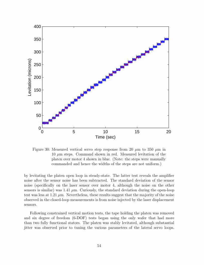
Vertical servoing from 20 µm to 350 µm in 10 µm steps is shown Figure 30. Noiseon the response is evident, largely injected from the laser displacement sensors. On the100 µm step, the mean of the measured vertical position is 100.05 µm, the standarddeviation is 1.59 µm, and the peak-peak measurement is 12.8 µm.
A magnified view of the step from 90 µm to 100 µm is shown in Figure 31. Althoughsomewhat obscured by noise, the rise time of the step is very similar the rise time pre-dicted in Figure 27, namely 0.005 seconds.
The noise injected by the laser displacement sensors and the current amplifiers can bedetermined by measuring the unlevitated platen, which reveals the sensor noise, followed
Figure 29: Platen constrained with tape to vertical motions only. Note thelaser displacement sensor beams visible on the top surface of theplaten.
53
0 5 10 15 200
50
100
150
200
250
300
350
400
Time (sec)
Levi
tatio
n (m
icro
ns)
Figure 30: Measured vertical servo step response from 20 µm to 350 µm in10 µm steps. Command shown in red. Measured levitation of theplaten over motor 4 shown in blue. (Note: the steps were manuallycommanded and hence the widths of the steps are not uniform.)
by levitating the platen open loop in steady-state. The latter test reveals the amplifiernoise after the sensor noise has been subtracted. The standard deviation of the sensornoise (specifically on the laser sensor over motor 4, although the noise on the othersensors is similar) was 1.41 µm. Curiously, the standard deviation during the open-looptest was less at 1.21 µm. Nevertheless, these results suggest that the majority of the noiseobserved in the closed-loop measurements is from noise injected by the laser displacementsensors.
Following constrained vertical motion tests, the tape holding the platen was removedand six degree of freedom (6-DOF) tests began using the only wafer that had morethan two fully functional stators. The platen was stably levitated, although substantialjitter was observed prior to tuning the various parameters of the lateral servo loops.
54

-0.02 -0.01 0 0.01 0.02 0.0384
86
88
90
92
94
96
98
100
102
104
Time (sec)
Levi
tatio
n (m
icro
ns)
Figure 31: Measured vertical servo step response from 90 µm to 100 µm. Com-mand shown in red. Measured levitation of the platen over motor 4shown in blue.
Unfortunately, on one of these early 6-DOF levitation tests (though not the first one),a disturbance, most likely in the feedback position from one of the laser displacementsensors, caused the platen to bounce hard on the stator windings. Multiple sparks wereobserved as the armature magnets shorted the stator windings, leaving several statorphases electrically open. With no further wafers available with more than two functionalstators, experiments unfortunately came to an end.
55

References
[1] M. Steven Rodgers et al. A new class of high force, low-voltage, compliant actuationsystems. In Solid-State Sensor and Actuator Workshop, Hilton Head Island, SouthCarolina, June 4–8, 2000.
[2] Stephen F. Bart et al. Design considerations for micromachined electric actuators.Sensors and Actuators, 14:269–292, 1988.
[3] Herbert H. Woodson and James R. Melcher. Electromechanical Dynamics. JohnWiley & Sons, Inc., New York, 1968.
[4] M. K. Ghantasala et al. Design and fabrication of a micro magnetic bearing. SmartMater. Struct., 9:235–240, 2000.
[5] A. R. von Hippel. Molecular Science and Molecular Engineering. Wiley, New York,1959. Chs. 3 and 5.
[6] Marc Madou. Fundamentals of Microfabrication: The Science of Miniaturization.CRC Press, Boca Raton, FL, second edition, 2002.
[7] Patrick L. Chapman and Philip T. Krein. Smaller is better? IEEE Ind. Appl. Mag.,9(1):62–67, January 2004.
[8] I. J. Busch-Vishniac. The case for magnetically driven microactuators. Sensors andActuators A, 33:207–220, 1992.
[9] Won-jong Kim, David L. Trumper, and Jeffrey H. Lang. Modeling and vector controlof planar magnetic levitator. IEEE Trans. on Industry Applications, 34(6):1254–1262, November 1998.
[10] H. Guckel et al. Micro electromagnetic actuators based on deep X-ray lithography.In Int. Symp. on Microsystems, Intelligent Materials and Robots, Sendai, Japan,September 27–29, 1995.
[11] Daniel J. Sadler, Sukirti Gupta, and Chong H. Ahn. Micromachined spiral inductorsusing UV-LIGA techniques. IEEE Trans. on Magnetics, 37(4):2897–2899, July 2001.
[12] Markus Ohnmacht, Volker Seidemann, and Stephanus Buttgenbach. Microcoils andmicrorelays—an optimized multilayer fabrication process. Sensors and Actuators,83:124–129, 2000.
[13] O. Cugat et al. Deformable magnetic mirror for adaptive optics: First results. In13th Ann. Int. Conf. on Micro Electro Mechanical Systems, pages 485–490, Miyazaki,Japan, January 23–27, 2000.
56

[14] Bertrand M. Dutoit, Pierre-A. Besse, and Radivoje S. Popovic. Planar multidipo-lar electromagnetic actuators. IEEE Trans. on Magnetics, 39(2):1026–1034, March2003.
[15] M. Nienhaus et al. Design and realization of a penny-shaped micromotor. In Symp.on Design, Test, and Microfab. of MEMS and MOEMS, pages 592–600, Paris, March1999.
[16] Chunsheng Yang et al. An axial flux electromagnetic micromotor. J. Micromech.Microeng., 11:113–117, 2001.
[17] V. Seidemann and S. Buttgenbach. A novel fabrication process for 3D meandershaped micro coils in SU8 dielectric and their application to linear micro motors.Proc. SPIE Int. Soc. Opt. Eng., 4407:304–309, 2001.
[18] P.-A. Gilles et al. Planar double-layer coil for brushless micromotor. In Mecatronics’01, pages 377–382, Besancon, France, October 9–11, 2001.
[19] David L. Trumper, Mark E. Williams, and Tiep H. Nguyen. Magnet arrays for syn-chronous machines. In 28th IEEE Ind. Appl. Conf., volume 1, pages 9–18, Toronto,October 3–8, 1993.
[20] Rajen Chanchani. Interconnection technology for next generation of integrated mi-crosystems. LDRD 26770, 2002. See ldrd.sandia.gov.
[21] Rajen Chanchani. Miniaturization of sar electronic assembly using sandia’s inte-grated substrate technology. LDRD 52579, 2003. See ldrd.sandia.gov.
[22] Rajen Chanchani. An integrated, stacked system-on-a-chip. LDRD 52554, 2004. Seeldrd.sandia.gov.
[23] P. M. Dentinger, W. M. Clift, and S. H. Goods. Removal of SU-8 photoresist forthick film application. Microelectronic Engineering, 61–62:993–1000, July 2002.
[24] K. Halbach. Design of permanent magnet multipole magnets with oriented rareearth cobalt material. Nuclear Instruments and Methods, 169:1–10, 1980.
[25] J. Ofori Tenkorang and J. H. Lang. Comparative analysis of torque production inHalbach and conventional surface-mounted permanent-magnet synchronous motors.In 30th IEEE Ind. Appl. Conf., volume 1, pages 657–663, Orlando, FL, October8–12, 1995.
[26] K. Atallah and D. Howe. Application of Halbach cylinders to brushless AC servomotors. IEEE Trans. on Magnetics, 34(4):2060–2062, July 1998.
57

[27] In-Kum Kim, Robert Kratz, and David Doll. General Atomics urban maglev tech-nology development. In Maglev’2002, Lausanne, Switzerland, September 3–5, 2002.Paper PP03101.
[28] Roger W. Brockett. Finite Dimensional Linear Systems. John Wiley & Sons, NewYork, 1970.
[29] N. N. Hancock. Matrix Analysis of Electrical Machinery. Pergamon Press, NewYork, second edition, 1974.
[30] David L. Trumper, Won-jong Kim, and Mark E. Williams. Design and analysisframework for linear permanent-magnet machines. IEEE Trans. on Industry Appli-cations, 32(2):371–379, March 1996.
58

Distribution
1 Professor Won-jong Kim221 Engineering/Physics BuildingTexas A&M UniversityCollege Station, TX 77843-3123
1 Professor Jeffrey H. LangRm. 10-176Massachusetts Institute of Technology77 Massachusetts Ave.Cambridge, MA 02139
1 Professor David L. TrumperRm. 35-016Massachusetts Institute of Technology77 Massachusetts Ave.Cambridge, MA 02139
2 MS 0501 Lawrence A. Jones 23321 MS 0501 Arnoldo Muyshondt 23321 MS 0503 David W. Plummer 23301 MS 0507 Bruce C. Walker 26001 MS 0509 Michael W. Callahan 23001 MS 0874 Rajen Chanchani 17451 MS 0961 Carol L. Jones Adkins 141011 MS 1310 Gerard E. Sleefe, 26141 MS 1425 Stephen J. Martin, 1707
1 MS 0161 Patent and Licensing Office, 115001 MS 0323 LDRD Office, 10112 MS 0899 Technical Library, 96161 MS 9018 Central Technical Files, 8945-1
59