
Mesh Forging: Editing of 3D-Meshes Using Implicitly Defined...
12
Eurographics Symposium on Geometry Processing (2003) L. Kobbelt, P. Schröder, H. Hoppe (Editors) Mesh Forging: Editing of 3D-Meshes Using Implicitly Defined Occluders G. H. Bendels † and R. Klein ‡ University of Bonn, Institute of Computer Science II, Computer Graphics, Römerstrasse 164, 53117 Bonn, Germany Abstract In recent years the ease of use and the flexibility in the editing process shifted into focus in modelling and ani- mation applications. In this spirit we present a 3D mesh editing method that is similar to the simple constrained deformation (scodef) method 9 . We extend this method to the so-called mesh forging paradigm by adding an oc- cluder to the editing environment. Our method resembles and was in fact motivated by the forging process where an anvil is used to give the manipulated object the desired shape. While users perform the editing operation by directly manipulating the 3D-mesh, the occluder is defined implicitly. To enable fine detail edits even in sparsely triangulated areas, we propose an adaptive refinement method that also allows the creation of sharp features where desired. The functionality and ease of use of our editing approach is shown by several examples. Categories and Subject Descriptors (according to ACM CCS): I.3.8 [Computer Graphics]: Applications; I.3.4 [Graphics Utilities]: Graphics Editors; I.3.5 [Computational Geometry and Object Modelling]: Object Modelling 1. Introduction and Previous Work Traditionally, the goal of research in geometric modeling and design was to find representations of 3D objects and modeling tools enabling a possibly intuitive and efficient de- sign process, the choice of the former usually influencing the range of choices for the latter and vice versa. A prominent example of such free form surface design methodologies are the piecewise polynomial tensor product surfaces. This rep- resentation reflects a balance of certain specific demands. On the one hand, there are the industrial requirements of enforc- ing some constraints on the result, e.g. smoothness, man- ufacturability, etc. On the other hand, the designer should be able to work efficiently, which calls for intuitivity and simplicity, especially in the early stages of design. As ge- ometric modeling finds applications in a wide spectrum of computer graphics applications, the focus of much research † [email protected] ‡ [email protected] effort shifts towards the latter. Originally, the needs of the in- dustry imposed requirements on geometric design methodol- ogy that made it cumbersome and time consuming. In case of tensor product surfaces, even the changes appearing concep- tually small are hard to execute. However, exact and prov- able geometric properties of the product are not relevant in numerous current application areas like film industry, com- puter games, etc. As the most relevant quality measure in these contexts is the visual appeal, much of the research fo- cusses on finding new modeling metaphors and techniques according to this criterion 35 . In case of implicit deformations, the objects are embedded in a space. The warping of these spaces causes a correspond- ing deformation of the object. According to the most pop- ular such approach called Free Form Deformations (FFD) 3, 37 , the surrounding space is defined as a multidimensional spline. This technique has been further improved and gener- alized 16 , moreover, it was adapted to generate animations by e.g. 16, 17 . The main advantage of these methods is that they enable a deformation that is independent of the complexity of the object being manipulated. However, as pointed out in c The Eurographics Association 2003.
-
Upload
vuongtuyen -
Category
Documents
-
view
226 -
download
0
Transcript of Mesh Forging: Editing of 3D-Meshes Using Implicitly Defined...

Eurographics Symposium on Geometry Processing (2003)L. Kobbelt, P. Schröder, H. Hoppe (Editors)
Mesh Forging: Editing of 3D-Meshes Using Implicitly DefinedOccluders
G. H. Bendels† and R. Klein‡
University of Bonn,Institute of Computer Science II, Computer Graphics,
Römerstrasse 164, 53117 Bonn, Germany
Abstract
In recent years the ease of use and the flexibility in the editing process shifted into focus in modelling and ani-mation applications. In this spirit we present a 3D mesh editing method that is similar to the simple constraineddeformation (scodef) method 9. We extend this method to the so-called mesh forging paradigm by adding an oc-cluder to the editing environment. Our method resembles and was in fact motivated by the forging process wherean anvil is used to give the manipulated object the desired shape. While users perform the editing operation bydirectly manipulating the 3D-mesh, the occluder is defined implicitly. To enable fine detail edits even in sparselytriangulated areas, we propose an adaptive refinement method that also allows the creation of sharp featureswhere desired. The functionality and ease of use of our editing approach is shown by several examples.
Categories and Subject Descriptors (according to ACM CCS): I.3.8 [Computer Graphics]: Applications; I.3.4[Graphics Utilities]: Graphics Editors; I.3.5 [Computational Geometry and Object Modelling]: Object Modelling
1. Introduction and Previous Work
Traditionally, the goal of research in geometric modelingand design was to find representations of 3D objects andmodeling tools enabling a possibly intuitive and efficient de-sign process, the choice of the former usually influencing therange of choices for the latter and vice versa. A prominentexample of such free form surface design methodologies arethe piecewise polynomial tensor product surfaces. This rep-resentation reflects a balance of certain specific demands. Onthe one hand, there are the industrial requirements of enforc-ing some constraints on the result, e.g. smoothness, man-ufacturability, etc. On the other hand, the designer shouldbe able to work efficiently, which calls for intuitivity andsimplicity, especially in the early stages of design. As ge-ometric modeling finds applications in a wide spectrum ofcomputer graphics applications, the focus of much research
† [email protected]‡ [email protected]
effort shifts towards the latter. Originally, the needs of the in-dustry imposed requirements on geometric design methodol-ogy that made it cumbersome and time consuming. In case oftensor product surfaces, even the changes appearing concep-tually small are hard to execute. However, exact and prov-able geometric properties of the product are not relevant innumerous current application areas like film industry, com-puter games, etc. As the most relevant quality measure inthese contexts is the visual appeal, much of the research fo-cusses on finding new modeling metaphors and techniquesaccording to this criterion 35.
In case of implicit deformations, the objects are embeddedin a space. The warping of these spaces causes a correspond-ing deformation of the object. According to the most pop-ular such approach called Free Form Deformations (FFD)3, 37, the surrounding space is defined as a multidimensionalspline. This technique has been further improved and gener-alized 16, moreover, it was adapted to generate animations bye.g. 16, 17. The main advantage of these methods is that theyenable a deformation that is independent of the complexityof the object being manipulated. However, as pointed out in
c© The Eurographics Association 2003.

Bendels et al / Mesh Forging
23, the placement and control of the lattice defining the de-formation is non-trivial. The improvements of 23, 24 remediedthese problems for the case of a single edit. In this systemthe user has to define only the initial control lattice, which isthen modified transparently to the user as she edits the ob-ject by dragging a point on the surface. However, since thecontrol points move according to the user’s input, the resultof a subsequent edit depends on a new control lattice, andmay thus be contra-intuitive, cf. 19, as it is different from anidentical edit in an untouched region.A prominent example of techniques relying on piecewisepolynomial representations is the classical NURBS model-ing approach 18. It reflects the idea of imposing a controlmesh directly on the surface of the object, the desired mod-eling effect is then achieved by modifying the control pointsof this mesh. However, since there are few degrees of free-dom in determining the scale of an edit and the topology ofthe control mesh, working with NURBS requires much ex-pertise and is time intensive.
The algorithmic generalization of piecewise polynomialrepresentations are the subdivision surfaces 15, 14, where asmooth surface is generated by iterative refinement of a con-trol mesh according to certain subdivision rules. Since sub-division surfaces essentially comprise a representation of anobject on different levels of scale, they may be utilized asa basis for Multiresolution Mesh Editing (MME) 41. Theidea of multiresolution editing is to use different levels ofdetail of the object to perform edits on different scales: De-tail edits are performed on finer meshes and large scale editson coarser meshes representing the same object. Saving thefiner meshes as details with respect to the coarser meshesprovides for detail preservation during large scale edits. Un-fortunately, since the one-ring of the edited vertex defines theregion of influence (ROI) of an edit, the subject of the editand the ROI are completely connectivity-defined and cannotbe chosen arbitrarily. Kobbelt et al. 27, 28 provided a solutionto this problem by abandoning the idea of defining the mul-tiresolution representations as a coarse-to-fine hierarchy ofnested meshes, and rather utilizing a hierarchy of scales interms of smoothness. The levels of detail are generated bya hierarchical mesh smoothing scheme. During the editingprocess the designer picks a region of interest defining thescale of the edit, and a handle, i.e. another region within theROI that undergoes the user-defined transformation. Eachtime the user transforms the handle, the mesh within the ROItransforms according to a constrained energy minimizationprinciple. This latter modeling metaphor stems from the areaof variational modeling 39 where the shape of a region of thesurface is a solution to a constrained optimization problem.Thus, the basis function of the deformation is completely de-termined by the shape of the handle and the boundary of theROI.In the above algorithms the user picks and specifies a trans-formation for parts of the object. Into this type of directediting, further research has been done. Lee 29 proposes a
method where the user picks a set of handle vertices in themesh and specifies modifications for these. For vertices inthe editing region, which is defined by the user beforehand,the transformations of the handle vertices are interpolatedusing multilevel B-Splines. These are parameterized over a2D embedding of the editing region, making this methodsuitable especially in flat regions. The influence of the han-dle vertices’ transformation on neighboring vertices is deter-mined by the size of the coarsest control lattice used in theB-spline interpolation.Recently, Pauly et al. 33 presented a modelling technique,transferring multiresolution results to the case of point-sampled geometry. In their setting, shapes are modified bydefining a so-called zero-region and a one-region. The one-region undergoes the full user-defined transformation (trans-lation or rotation), whereas the zero-region remains fixedand a predefined blending function is used to create a smoothtransition between the two regions. Also focussing on point-sampled geometry Zwicker et al. 42 generalize standard 2Dimage editing techniques to 3D, reconstructing well-knownpixel editing tools.While the methods mentioned so far mainly apply to modi-fying existing shapes, SKETCH40, SKIN 30 and TEDDY 25,which were later extended in 26, are among those methodsgenerating models from scratch. Modifying shapes in theseapproaches is realised using a method called oversketching,i.e. drawing parts of the silhouette of the shape anew.
Although interactive display of implicit surfaces 5 is stilla challenge, implicit modeling has gained more and more re-search attention in recent years. Distance surfaces like blobs4, meta-balls 10, soft objects 7, and convolution surfaces 6 arepopular in Computer Animation since the geometric "skele-ton", with respect to which they are defined, can be used asan internal structure to control the animation 11 and even forLOD-representations13, 1. Several methods have been pre-sented to tackle the so-called "unwanted blending problem",e.g. 2. Furthermore, the availability of inside-outside infor-mation allows for efficient collision detection and response32.
Of particular relevance for this paper is the work of Bor-rel et al. presented in 8, 9 and later extended in 36. The algo-rithm proposed in this paper is similar in the way the dis-placement of vertices in the neighbourhood of user-definedhandles are computed but is extended to incorporate sharpfeatures where desired. In addition to that, we use geodesicdistances to define an object-inherent parametrization for ourshape functions, thus freeing the user of the need to adjustobject-independent region of influence definitions as in e.g.36.Anisotropic parameterizations are feasible through multiple,handle-independent anchors. Moreover we introduce editingoccluders, i.e. implicitly defined 3D-objects that influencethe editing operations. With these editing occluders we de-fine a novel editing paradigm resembling the forging processwhere an anvil is used to give an object the desired shape.
c© The Eurographics Association 2003.

Bendels et al / Mesh Forging
The main contributions of this paper are a closed formula-tion for the editing method including the occluder field influ-ence. By representing the model to be deformed as a trian-gular mesh, while the occluder is defined implicitly, our ap-proach takes advantage of both representations respectively,in particular the efficient collision detection. Moreover, wetransfer the concept of Precise Contact Modeling (PCM) tothe setting of triangular meshes.
The rest of this paper is organized as follows. In section2, we give an overview over the editing process, describethe underlying mathematical formulation and the influenceof shape functions. Section 3 introduces what we call themesh forging process. The adaptive refinement method pro-posed for the shape function edits is described in section 4.Results and examples of models manipulated with our toolare given in section 5. This section also gives conclusionsand discusses future directions of research.
2. Editing Process
Figure 1: The user interface with an exemplary arm move-ment. The model was reconstructed from a laser range scan.On the right hand side we see the modified model afterapplying a translation modification based on geodesic dis-tances. The arm is lifted without affecting the torso. Note thedetail preservation leading to the the realistic folds of thesleeve.
In this section we will describe how the user’s specifi-cation of the modification for a set of handle vertices isused to produce a smooth, detail-preserving and intuitive de-formation of the whole mesh. Due to the similarity to ourmethod and since it is not widely known, we briefly reviewthe method presented in 36 in section 2.1. In section 2.2 wedescribe how this methodology can be extended to rotations,while the rest of the section focusses on defining suitableparameterizations of the editing region.
2.1. Translations
We first consider the case where a user specifies a translationfor the handle vertices. The main idea is that every geometric
modification of a 3D shape can be interpreted as a displace-ment function
d :�3 →�3 (1)
that assigns to every point p ∈ �3 a displacement vectord(p) such that the resulting point positions after the modi-fication are given as
pnew = pold +d(pold). (2)
In our setting the values of this displacement function (alsoreferred to as constraints 9) are defined at the handle verticesonly. For all other vertices the mapping has to be determined.
The idea to solve this problem is to write the displace-ments of all vertices as a weighted sum of virtual displace-ment vectors for the handle vertices – which we call partialdisplacements d j in contrast to the total displacements d(p)
d(p) =k
∑j=1
α j(p)d j. (3)
Here k is the number of handle vertices and
α j :�3 →�, j = 1, . . . ,k
are weight functions. Note that for each p, α j(p) can beinterpreted as a special weight corresponding to the handlevertex p j.
The above formulation allows for the desired degree offreedom for choosing the set of handle vertices and the prop-erties of the edit. Please note that simply setting d j = d(p j)is not a satisfying choice, as becomes clear when we con-sider the case where the ROI of different handle verticesoverlap in a way such that α j(pi) �= 0 for a pair of handlevertices pi, p j, i �= j. In this case pi undergoes (in addition toits own transformation) a transformation induced by the han-dle vertex p j. This would render the handle vertices movingto positions different than defined by the user, unless we im-pose strict normalization conditions on the weight functions,which, in turn, would prohibit the use of arbitrary and user-defined weight functions. Therefore, we calculate the partialdisplacements according to the weight functions.
Since, by user-definition, d(p j) is known for the handlevertices p1, . . . ,pk, equation (3) leads to a linear system ofequations (
d(p j))
j=1,...,k= A
(d j
)j=1,...,k
(4)
with
A =(
α j(pi))
i=1,...,kj=1,...,k
(5)
giving us 3k equations for the total displacements d(p j) with3k unknowns d j , 1 ≤ j ≤ k.
Of course, ill-conditioned weight function choices (suchas α j(p j) = 0) might leave the matrix A singular or close
c© The Eurographics Association 2003.

Bendels et al / Mesh Forging
to singular. This can easily be avoided using either a SVDfor detecting and prohibiting those ill-conditioned modifica-tions of the shape function or ROI, or a pseudo-inverse assuggested in 34. For a detailed discussion cf. 9.
After solving (4), (3) is used again to compute the totaldisplacements for the other vertices.
Please note that for a single handle vertex p0, (3) reducesto
d(p) = α(p)d0
with d0 = 1/α(p0)d(p0), leading to a very efficient formu-lation for the frequent case of single handle vertex edits.
2.2. Rotations
As stated above, every transformation can be interpreted as adisplacement field, and thus even rotation-like modificationsof the object (like turning a person’s head) are in theory pos-sible with the above formulation. In general, to achieve sat-isfying results, this would require a considerable number ofhandle vertices, though. Therefore we propose using a dif-ferent kind of constraints for rotational editing operations.Instead of defining total displacements for the handle ver-tices, the user defines total rotations η1, . . . ,ηk with respectto an axis n.
In our current implementation, the rotation axis is definedby the screen center and the viewing direction. Analogouslyto the displacement field in the translation case, we define arotation field
η :�3 →�
that assigns to every point p ∈�3 a rotation angle η(p) suchthat the resulting point positions after the modification aregiven as
pnew = R(η(pold),n) pold, (6)
where R(η,n) is the rotation matrix that rotates the spaceby an angle of η about the axis n. As in the translation con-text, the values of this rotation map are defined at the handlevertices only. For the other vertices the mapping has to bedetermined as above using
η(p) =k
∑j=1
α j(p)η j
with partial angles η j and total angles η(p).
2.3. Parametrizations and Shape Functions
A very simple approach for a weight function could be forexample α j(pi) = δi j leading to d(p j) = d j and η(p j) = η j.
Note the similarity of this formulation to standard scat-tered data interpolation problems. The above choice of
weight functions would give us the generally unsatisfyingapproach that moves the handle vertices as specified andleaves all other vertices unchanged. Instead, we define theweight functions to be a composition
α j(p) = ϕ◦ γ j(p)
of a shape function
ϕ :�≥0 →� (7)
and a parametrization of the object
γ j :�3 →�≥0. (8)
The mathematical framework presented in the previous sec-tions is applicable with any distance function γ :�3×�3 →�
≥0 if we define
γ j(p) = γ(p j,p). (9)
In order to achieve intuitive results however, γ should be cho-sen such that it defines intuitive neighborhoods on the object.
Although appropriate in some occasions, choosing Eu-clidean distances
γ(p,q) = ‖p−q‖as in 38 would make it virtually impossible, for example,to bend a person’s index finger without interfering with theother fingers.
We propose using geodesic distances instead, i.e. thelength of the shortest curve between p and q on the boundaryof the object. Using definition (9), the object is thus parame-terized via geodesic distance fields with respect to the handlevertices p j .
The impact of this choice on the resulting editing oper-ations is visualized in figure 3(a) <see color section> thatshows an editing operation applied to a simple triangle meshrepresentation of a hand. Pictures (1) and (3) show the origi-nal mesh with the region of influence colored in red. Pictures(2) and (4) show the modified meshes, after an identical edithas been performed (based on Euclidean distances in the toprow and on geodesic distances in the bottom row). Note howthe middle and ring finger have been deformed in picture (2),whereas in picture (4) only the index finger has been modi-fied (as desired in this example).
Raffin et al. 36 propose user-definable hulls of influencesurrounding the parts of the object that should be affected toachieve the above results, but we feel that the geodesic dis-tances provide for a useful object-inherent parametrizationfor the modification of surfaces, and therefore lead to a moreconvenient user interface, freeing the user from the need tofit hulls of influence to the specific editing situation (whichmight be difficult, if the fingers e.g. are very close).
To efficiently compute the geodesic distances between thehandle vertices and all other vertices, our implementationuses the algorithm from 31. Nevertheless this is computation-ally nontrivial, but it does not prevent interactive response,
c© The Eurographics Association 2003.

Bendels et al / Mesh Forging
since it is performed only when the vertices are selected ordeselected, not during dragging.
Figure 2: Different shape function settings applied to thesame editing operation
Shape Functions (cf. figure 2) provide for more flexibil-ity and degrees of freedom than e.g. the trivariate Bern-stein polynomials used in FFD methods or the parameterizedGaussian functions used in 38.
In many cases, choosing smooth shape functions will besufficient, but in other cases the user might want to intro-duce sharp features into the edited area. This can easily beachieved using our approach by employing the appropriateshape function, given that the triangulation of the underly-ing mesh is adequately fine (see section 4).
2.4. Separating Handles and Anchors
The method presented so far relies on an object parametriza-tion with respect to the handle vertices. Whereas this resultsin an intuitive and easy-to-use tool, there is no theoreticalobligation to identify the handles used to define the totaltransformations with the anchors used to define the objectparametrization. In some occasions, it might be desirable toparameterize the object with respect to other vertices thanthe handles. As an example, one can think of turning a per-son’s head (with a rigid head and a smoothly twisted neck)while the rest of the body remains unchanged down from theshoulders (see figure 3(b) in the color section). In this case itis useful to define the parametrization with respect to anchorvertices at the top of the head, while the handle vertex canbe picked somewhere else on the mesh.
Additionally, separating handles from anchors has anotheradvantage: We can extend this line of thought to a multipleanchors - single handle-approach, i.e. the parametrization ofthe object is defined with respect to a set of anchor verticesa j
1, . . . ,ajl rather than to a single anchor vertex. Thus we are
able to define anisotropic distance fields on the object, free-ing us from the limitation of rotationally symmetric parame-terizations. In our current implementation, the distance field
defining the parametrization corresponding to handle vertexp j is then defined for every mesh vertex p as
γ j(p) = min1≤i≤l
γ(a ji ,p). (10)
It is known that the iso-values of γ j(p) in equation (10)do not form smooth curves. But implementing known tech-niques from implicit modelling (e.g. following the ideas ofConvolution Surfaces from 5) into our setting is a straight-forward extension leading to smooth distance fields.
3. Mesh Forging Process
Figure 3: Example of a mesh forging operation. A vertexof the editing object (the grey coloured ball) is picked anddragged. The occluder (the green cylinder) induces a forcefield that superposes the displacement field and drives thetransformed vertices around it.
The basic idea of mesh forging is to add an occluder (theanvil) to the editing space in form of a force field, therebyreplicating the Precise Contact Modelling (PCM) methodol-ogy (see below) in the context of mesh editing. Here, the oc-cluder field controllably superposes (and thereby modifies)the transformation applied to the vertices of the mesh (cf.figure 3 for an example).
In implicit modelling, contact situations between two sur-faces
Si = {p ∈� | fi(p) = c}, i ∈ {1,2}are easily detected by checking for points p satisfying bothf1(p)≤ c and f2(p)≤ c. For these points in the interpenetra-tion region, a compression term is added to the field function
c© The Eurographics Association 2003.

Bendels et al / Mesh Forging
fi. If only S1 is deformable and S2 rigid, f1(p) is replaced by
c+(c− f2(p))
for all p in the interpenetration region.In order to mimic volume preservation in the contact regions,a dilation term b(p) is added for points p in the propagationregion
{p ∈� | c̃ ≥ f2(p) > c}with some constant c̃. For an in-depth description of thePCM methodology, see 12, 32.
3.1. The Algorithm
Figure 4: Successive occluder influence. The stippled vectorindicates the vertex transformation d(p) as defined by theediting operation, the green vectors represent the n-th partdn(p) = 1/n d(p) of this transformation. The dashed redvectors indicate the repelling force due to the occluder field.Note how the considered vertex p moves along the boundaryof the occluder leading to the expected editing behaviour.
Let us start with an example to motivate our algorithm.Suppose that in a mesh editing environment, we have a ver-tex p ∈�3 in the mesh and, defined by some modelling op-eration, a total displacement d(p) for this vertex. In orderto detect collisions even for larger edits, we first subdivided(p) into N pieces – otherwise it would be possible to movethrough the occluder or through occluder details. Our algo-rithm then leads to the following sequence of transforma-tions (see figure 4):
p �→ p1 = p + 1N d(p)+o(p+ 1
N d(p))p1 �→ p2 = p1 + 1
N d(p)+o(p1 + 1N d(p))
...pN−1 �→ pN = pN−1 + 1
N d(p)+o(pN−1 + 1N d(p))
(11)
Here, o(p) is the occluder field and corresponds to the com-pression term in the implicit modelling context. To describethe editing process in general, we get the following recursivealgorithm:
pi−1 �→ pi =pi−1 + 1N d(p)+o(pi−1 + 1
N d(p)) (12)
Our new transformation equation can then be written as
p �→ p+d(p)+N
∑i=1
o(pi). (13)
This is a natural generalization of equation (2).
Although the above formulation would allow for a com-plete tracking of the editing path as indicated by the mousemovement, we still evaluate the displacement field d at ponly.
3.2. Defining the Occluder Field
For the efficient detection of contact situations we define theoccluder implicitly as a signed distance vector field, i.e. forevery point p ∈�3, in addition to the signed distance
δ : �3 → �
p �→ signed distance of pto occluder surface,
(14)
we store the direction
∆ : �3 → �
3
p �→ (p0 −p)/‖p0 −p‖, (15)
to the closest point p0 on the occluder surface. We discre-tionarily choose δ(p) < 0 iff p is inside the occluder.
The well-known Adaptively Sampled Distance Fields(ADFs) 20 serve well for our purpose here since we can usethe sample density of the ADF as a hint for the samplingdistance for the editing paths. We propose using the voxelwidth as a local path sampling rate. This inherently allowsfor feature detection in the occluder field.
Although our current implementation makes use of ana-lytically defined occluders, a future toolbox will contain aset of predefined signed distance fields. The distance fieldsto user-defined occluders have to be calculated in a prepro-cessing step. However, this does not prevent user interactionwith the occluder: Resizing, translating, rotating are all triv-ially available without changing the actual values in the dis-tance field. Evaluating the "transformed" distance field at aposition p simply requires the evaluation of the original dis-tance field after applying the inverse transformation to p.
Having access to the distance values and to the closestpoint on the occluder surface at any position in space, wehave now all the ingredients to formulate our occluder forcefield. We define
o : �3 ×�3 → �
3
(p,d(p)) �→ o(p,d(p))(16)
as follows:
o(p,d(p)) = −ψ(δ(p+d(p))) ·∆(p+d(p))
where ψ : �3 → � is an influence function that can bethought of as a kind of shape function for the occluder and
c© The Eurographics Association 2003.
Bendels et al / Mesh Forging
that determines the effective impact of the occluder field. De-pending on the actual editing circumstances, different influ-ence functions are appropriate, e.g.
ψ(δ(p)) ={
δ(p) : δ(p) ≤ 0exp(−δ2(p)) : δ(p) > 0.
(17)
This influence function guarantees that vertices penetratingthe occluder are transferred to the occluder surface, regard-less of the underlying editing operation, and vertices comingclose to the occluder surface but not penetrating it are alsorepelled. This prevents (to some extent) the fingers from flat-tening in figure 2 <see color section>.
The rationale behind formulating o = o(p,d(p)) insteadof o = o(p), i.e. making the occluder field not only depen-dent on the locus p but also on the editing direction d(p)is that this leads to a more flexible approach. The most sig-nificant benefit from this formulation is that we are able toassure that the occluder has no bigger effect than the orig-inating displacement and therefore to restrict the occluderinfluence to the editing region of influence. This can easilybe done by including ‖d(p)‖ as a factor into equation (17).
4. Adaptive Refinement
Figure 5: Left: For some edits, the triangles might be toolarge to represent fine details as defined by the shape func-tion (top). Result after refinement (bottom). Right: The er-ror induced by applying a transform to a polygonal meshas specified by the shape function without refining the meshcorresponds to the error induced by linearly interpolatingthe shape function between two adjacent vertices in themesh.
Editing operations change the geometric properties ofthe underlying mesh. Edits are likely to add small detailsthat might not be representable by the current triangulation.Therefore an adaptive refinement method has to be applied,e.g. as proposed in 22 or 21. Here, local curvature informa-tion (by midpoint subdivision or by vertex normal deviation,resp.) is used to decide if further refinement is required.
In addition to this general refinement technique, we pro-pose exploiting the shape function information to decide ifand where edges have to be subdivided in order to be able to
incorporate sharp feature edits. Therefore, we consider theerror induced by linearly interpolating the shape function be-tween adjacent vertices (see figure 5). For a handle vertex pand an edge (v0,v1) we define
εpv0,v1 = max
t0≤t≤t1
∣∣∣∣ϕ(t)−ϕ(t0)+t − t0t1 − t0
(ϕ(t1)−ϕ(t0))∣∣∣∣(18)
with t0 = γ(p,v0), t1 = γ(p,v1) and ϕ and γ as defined in (7)and (8) respectively. For multiple handle vertices p1, . . . ,pkwe define
εv0,v1 = maxp=p1,...,pk
εpv0,v1 .
Edges are subdivided if ε exceeds a user-controllable thresh-old.
Let tmax be the parameter in [t0, t1] for which the righthand side in (18) becomes maximal. A new vertex will thenbe inserted into this edge at the temporary position
vmax = v0 +tmax
t1 − t0(v1 −v0) .
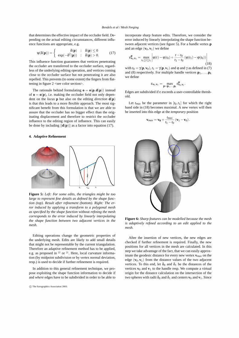
Figure 6: Sharp features can be modelled because the meshis adaptively refined according to an edit applied to themesh.
After the insertion of new vertices, the new edges arechecked if further refinement is required. Finally, the newpositions for all vertices in the mesh are calculated. In thisstep we take advantage of the fact, that we can easily approx-imate the geodesic distance for every new vertex vmax on theedge (v0,v1) from the distance values of the two adjacentvertices. To this end, let δ0 and δ1 be the distances of thevertices v0 and v1 to the handle resp. We compute a virtualorigin for the distance calculation on the intersection of thetwo spheres with radii δ0 and δ1 and centers v0 and v1. Since
c© The Eurographics Association 2003.

Bendels et al / Mesh Forging
the intersecting circle is orthogonal to the edge (v0,v1), ev-ery point on it has the same distance to vmax which is used asthe desired approximation of the geodesic distance in vmax
(cf. 31).
Whereas the above refinement strategy allows for sharpfeature editing by recursively subdividing edges where in-dicated by the shape function, further refinement might berequired to model contact situations, as can be seen in therightmost picture in figure 2 <see color section>. We are cur-rently working on an approach to extend our adaptive refine-ment strategy in this direction.
5. Results and Discussions
As an example for the power of our rotation scheme for an-imation purposes, we consider the famous Stanford Bunny.Figure 1 <see color section> shows how the bunny’s ears canbe transformed with one single editing operation consistingof as few as four editing steps. Firstly, the tips of the twoears are selected as handles; secondly, we make a prelimi-nary choice for the ROI of the edit (we can always changethat at later stages of the edit, the preliminary choice onlyimproves the visual feedback during the following steps). Inour current implementation, the rotation axis is defined bythe screen center and the viewing direction. Hence we posi-tion the bunny accordingly and drag the tips of the ears tothe desired position (figure 1 (4) <see color section> ). Afterthe transformation for the tips of the ears has been specified,we can interactively modify the shape function in order toachieve a realistic look of the ears. It would have been veryhard to achieve this result using the translation scheme only.
Figure 3(b) <see color section> is an example for the useof the anisotropic rotational editing scheme. The rotationaxis was chosen in this example approximately parallel tothe spine. Note that only the head has turned, the shoulderregion remained fixed. In order to have the head remain rigidwhile the neck is twisted, few anchor vertices have been cho-sen on the top of the head, and a single handle vertex waspicked on the nose. The multiple anchor vertices are nec-essary because otherwise it had been difficult to adjust theregion of influence such that only the neck is twisted (a headis not perfectly round, so choosing only one anchor vertexat the top will not lead to a satisfying region of influencebehavior – with just one anchor vertex either the shoulderregion will be influenced or "outer regions" as the chin willnot move rigidly with the rest of the head).
The possibility of choosing multiple anchor vertices isalso feasible to solve problems arising with the use ofgeodesic distances as the basis of our object parametrization:Certain object surface features (imagine a ring with a promi-nent gem on the finger in the example depicted in figure 3(a)<see color section>) can cast "geodesic shadows". We cur-rently examine in how far surface smoothing before the cal-culation of the geodesic distances diminishes or solves thisproblem.
Nevertheless, as geodesic distances reflect properties in-herent to the surface, they yield in general more intuitiveediting results than Euclidean distances, without having todefine object-independent hulls of influence as proposed in36.
Our current implementation is based on the superpositionof distance fields computed with respect to the single anchorvertices. As pointed out in section 2 this does not lead to asmooth distance field. However, implementing results of im-plicit modelling (e.g. convolution surfaces6) will lead to aconvenient method to define smooth distance fields with re-spect to the anchor points as skeletons, where desired. More-over, allowing other primitives like edges or triangles to beused for these skeletons will provide for a powerful tool todefine regions of influence for the editing operations. Thiscould be incorporated into our approach without even chang-ing the user interface.
With our adaptive refinement method we are able to modelsharp features even in sparsely triangulated regions of themesh, as can be seen from figure 6. However, our refine-ment strategy is based on the shape function edit only. Itdoes not take into account the underlying geometric prop-erties of the object in the editing region. Therefore, even incases in which the edit actually reduces details on the mesh,new vertices might be inserted. We’re currently working ona method to prohibit the insertion of vertices in these cases,yet maintaining the efficiency of analyzing only the shapefunction.
So far, our implementation is purely vertex-based, the usercan only choose vertices as handles and anchors. It wouldbe desirable (and a straight forward extension) to allow forarbitrary points on the object surface to be picked.
In many cases picking one or more vertices on the meshand dragging them to the desired position is sufficient andleads to satisfying results. In some occasions, though, thatmight not give users enough flexibility. Therefore we allowusers to specify the parametrization of the object indepen-dently from the handles (cf. section 2.4). Among other ben-efits, this simplifies the editing operation in rotation caseswhere the distance field is defined on (or close to) the rota-tion axis. In these cases, it is convenient to grab a differentpoint on the object to specify the rotation angles.
Our mesh editing approach can not only be used for an-imation but also for modelling purposes as it can be seenfrom figure 7. Starting from a sphere, we create a completeteapot. Note how the shape function can be used to modeldetails on the teapot’s handle with a rotational edit.
References
1. A. Angelidis and M.-P. Cani. Adaptive implicit model-ing using subdivision curves and surfaces as skeletons.In Solid Modelling and Applications. ACM, June 2002.Saarbrucken, Germany.
c© The Eurographics Association 2003.

Bendels et al / Mesh Forging
Figure 7: Creating a teapot (top right) from a primitive (top left) with just a few editing operations. The basic editing operationsare depicted together with the corresponding shape functions (left and bottom). The arrows indicate the modification applied tothe handles. Note how the shape function can not only be used to adjust the overall shape of the edit but also to add details tothe model (see the teapot’s handle in the last editing step and in the final result).
2. A. Angelidis, P. Jepp, and M.-P. Cani. Implicit mod-eling with skeleton curves: Controlled blending in con-tact situations. In Shape Modeling International. ACM,IEEE Computer Society Press, 2002. Banff, Alberta,Cananda.
3. A. H. Barr. Global and local deformations of solidprimitives. In Proceedings of the 11th annual confer-ence on Computer graphics and interactive techniques,pages 21–30, 1984.
4. J. F. Blinn. A generalization of algebraic surface draw-ing. ACM Transactions on Graphics (TOG), 1(3):235–256, 1982.
5. J. Bloomenthal. Introduction to Implicit Surfaces. Mor-gan Kaufmann Publishers, Inc., 1997.
6. J. Bloomenthal and K. Shoemake. Convolution sur-faces. In Proceedings of the 18th annual conference onComputer graphics and interactive techniques, pages251–256. ACM Press, 1991.
7. J. Bloomenthal and B. Wyvill. Interactive techniquesfor implicit modeling. Computer Graphics (1990 Sym-posium on Interactive 3D Graphics), 24(2):109–116,1990.
8. P. Borrel and D. Bechmann. Deformation of n-dimensional objects. In Proceedings of the firstACM symposium on Solid modeling foundations andCAD/CAM applications, pages 351–369. ACM Press,1991.
9. P. Borrel and A. Rappoport. Simple constrained defor-mations for geometric modeling and interactive design.ACM Transactions on Graphics (TOG), 13(2):137–155,1994.
10. B.Wyvill, C.McPheeters, and G.Wyvill. Data structurefor soft objects. The Visual Computer, 2(4):227–234,1986.
11. M.-P. Cani. Implicit representations in computer ani-mation : a compared study. In Proceedings of Implicit
c© The Eurographics Association 2003.

Bendels et al / Mesh Forging
Surface ’99, Sep 1999. Invited paper.
12. M.-P. Cani and M. Desbrun. Animation of deformablemodels using implicit surfaces. IEEE Transactions onVisualization and Computer Graphics, 3(1), Mar 1997.Published under the name Marie-Paule Cani-Gascuel.
13. M.-P. Cani and S. Hornus. Subdivision curve primi-tives: a new solution for interactive implicit modeling.In Shape Modelling International, Italy, May 2001.
14. E. Catmull and J. H. Clark. Recursively gener-ated b-spline surfaces on arbitrary topological meshes.Computer-Aided Design, 10:350–360, November 1978.
15. G. Chaikin. Short note: An algorithm for high-speedcurve generation. Computer Graphics and Image Pro-cessing, 3:346–349, 1974.
16. S. Coquillart. Extended free-form deformation: a sculp-turing tool for 3d geometric modeling. In Proceed-ings of the 17th annual conference on Computer graph-ics and interactive techniques, pages 187–196. ACMPress, 1990.
17. P. Faloutsos, M. van de Panne, and D. Terzopoulos.Dynamic free-form deformations for animation synthe-sis. IEEE Transactions on Visualization and ComputerGraphics, 3(3):201–214, /1997.
18. G. Farin. Curves and Surfaces for Computer Aided Ge-ometric Design: A Practical Guide. Academic PressInc., 1993.
19. N. Frisch and T. Ertl. Deformation of finite elementmeshes using directly manipulated free-form deforma-tion. In Proceedings of the seventh ACM symposium onSolid modeling and applications, pages 249–256. ACMPress, 2002.
20. S. F. Frisken, R. N. Perry, A. P. Rockwood, and T. R.Jones. Adaptively sampled distance fields: a generalrepresentation of shape for computer graphics. In Pro-ceedings of the 27th annual conference on Computergraphics and interactive techniques, pages 249–254.ACM Press/Addison-Wesley Publishing Co., 2000.
21. J. E. Gain and N. A. Dodgson. Adaptive refinementand decimation under free-form deformation. In Euro-graphics UK ’99, 1999.
22. J. Greissmair and W. Purgathofer. Deformation ofsolids with trivariate b-splines. In Computer GraphicsForum, pages 137–148, 1989.
23. W. M. Hsu, J. F. Hughes, and H. Kaufman. Directmanipulation of free-form deformations. ComputerGraphics, 26(2):177–184, 1992.
24. S.-M. Hu, H. Zhang, C.-L. Tai, and J.-G. Sun. Directmanipulation of ffd: efficient explicit solutions and de-composible multiple point constraints. The Visual Com-puter, 17, 2001.
25. T. Igarashi, S. Matsuoka, and H. Tanaka. Teddy: asketching interface for 3d freeform design. In Proceed-ings of the 26th annual conference on Computer graph-ics and interactive techniques, pages 409–416. ACMPress/Addison-Wesley Publishing Co., 1999.
26. O. Karpenko, J. F. Hughes, and R. Raskar. Free-formsketching with variational implicit surfaces. ComputerGraphics Forum, 21(3), September 2002.
27. L. Kobbelt, S. Campagna, J. Vorsatz, and H.-P. Sei-del. Interactive multi-resolution modeling on arbitrarymeshes. Computer Graphics, 32(Annual ConferenceSeries):105–114, 1998.
28. L. P. Kobbelt, T. Bareuther, and H.-P. Seidel. Multires-olution shape deformations for meshes with dynamicvertex connectivity. Computer Graphics Forum, 19(3),August 2000.
29. S. Lee. Interactive multiresolution editing of arbitrarymeshes. Computer Graphics Forum, 1999.
30. L. Markosian, J. M. Cohen, T. Crulli, and J. Hughes.Skin: a constructive approach to modeling free-formshapes. In Proceedings of the 26th annual confer-ence on Computer graphics and interactive techniques,pages 393–400. ACM Press/Addison-Wesley Publish-ing Co., 1999.
31. M. Novotni and R. Klein. Computing geodesic dis-tances on triangular meshes. In The 10-th InternationalConference in Central Europe on Computer Graph-ics, Visualization and Computer Vision (WSCG), pages341–347, 2002.
32. A. Opalach and M. Cani-Gascuel. Local deformationsfor animation of implicit surfaces. In W. Straßer, editor,13th Spring Conference on Computer Graphics, pages85–92, 1997.
33. M. Pauly, R. Keiser, L. Kobbelt, and M. Gross. Shapemodeling with point-sampled geometry. In Proceed-ings of the 30th annual conference on Computer graph-ics and interactive techniques (to appear), 2003.
34. R. Penrose. A generalized inverse for matrices. In Proc.Cambridge Philos. Soc., pages 406–413, 1955.
35. R. N. Perry and S. F. Frisken. Kizamu: a system forsculpting digital characters. In Proceedings of the 28thannual conference on Computer graphics and interac-tive techniques, pages 47–56. ACM Press, 2001.
36. R.Raffin, M. Neveu, and F. Jaar. Curvilinear displace-ment of free-form-based deformation. The Visual Com-puter, 16(1):38–46, 2000.
37. T. W. Sederberg and S. R. Parry. Free-form deformationof solid geometric models. In Proceedings of the 13thannual conference on Computer graphics and interac-tive techniques, pages 151–160. ACM Press, 1986.
c© The Eurographics Association 2003.

Bendels et al / Mesh Forging
38. S.Yoshizawa, A. G. Belyaev, and H. Seidel. A simpleapproach to interactive free-form shape deformations.In Pacific Graphics 2002 Proceedings, pages 471–474,2002.
39. W. Welch and A. Witkin. Free-form shape design usingtriangulated surfaces. Computer Graphics, 28(AnnualConference Series):247–256, 1994.
40. R. C. Zeleznik, K. P. Herndon, and J. F. Hughes.Sketch: an interface for sketching 3d scenes. In Pro-ceedings of the 23rd annual conference on Computergraphics and interactive techniques, pages 163–170.ACM Press, 1996.
41. D. Zorin, P. Schröder, and W. Sweldens. Interac-tive multiresolution mesh editing. Computer Graphics,31(Annual Conference Series):259–268, 1997.
42. M. Zwicker, M. Pauly, O. Knoll, and M. Gross.Pointshop 3d: an interactive system for point-based sur-face editing. In Proceedings of the 29th annual confer-ence on Computer graphics and interactive techniques,pages 322–329. ACM Press, 2002.
c© The Eurographics Association 2003.

Figure 1: Application of the rotational editing scheme. The tips of the bunny’s ears are picked and dragged, while not only theregion of influence (indicated by the red colored area (1) and (2)) but also the shape of the edit can interactively be modified andadjusted ((4) and (5)) using the shape function ((3) and (6) resp.) until the impression is visually satisfying. Picture (7) showsthe corresponding edit using the translational scheme with a slightly adjusted shape function to produce a smooth changeoverat the bunny’s head.
Figure 2: Modelling a hand taking grip on a ball. The fingers of the hand are transformed by a simple drag on the finger tips.The force field induced by the occluder causes the fingers to be shaped around the ball instead of intruding into it. Influencefunctions prevent the fingers from flattening.
Figure 3: (a) Editing operation with Euclidean (pictures 1 and 2) and geodesic (3 and 4) distances. The region of influence isindicated by red color, the little sphere at the tip of the index finger is the handle that is dragged during the edit. Note how themiddle and ring finger are modified together with the index finger in the upper right picture. (b) Turning a model’s head. Asindicated by the red color, the shoulder region remains fixed, while the head is turned (using the blue handle on the nose). Byusing multiple (three) anchors (green spheres at the top of the head) we define an anisotropic ROI s.t. the head is turned rigidly,with a smooth changeover at the neck.