
MERLIN Embedded Industrial Internet Appliance · MERLIN Embedded Industrial Internet Appliance ......
40
CONTROL SYSTEMS J640 2192-10850-000-000 Page 1 MERLIN Embedded Industrial Internet Appliance Library Technical Manual Product Information Full information about other Arcom products is available by contacting our Website at: www.arcomcontrols.com Useful Contact Information Customer Support Europe Customer Support US Tel: +44 (0)1223 412 428 Fax: +44 (0)1223 403 409 E-mail: [email protected] Tel: 816 941 7025 Fax: 816 941 7807 E-mail: [email protected] Sales offices Sales hotlines United Kingdom: Arcom Control Systems Ltd Clifton Road Cambridge CB1 7EA, UK Tel: 01223 411 200 Fax: 01223 410 457 E-mail: [email protected] United States: Arcom Control Systems Inc 13510 South Oak Street Kansas City MO 64145 USA Tel: 816 941 7025 Fax: 816 941 7807 E-mail: [email protected] Belgium: Groen Nummer: Tel: 0800 7 3192 Fax: 0800 7 3191 France: Numero Vert Tel: 0800 90 84 06 Fax: 0800 90 84 12 Germany: Kostenlose Infoline: Tel: 08001 824 511 Fax:08001 824 512 Netherlands: Gratis Nummer: Tel: 0800 0221136 Fax: 0800 0221148 Italy: Numero Verde: Tel: 0800 790841 Fax: 0800 780841 Whilst Arcom’s sales team is always available to assist you in making your decision, the final choice of boards or systems is solely and wholly the responsibility of the buyer. Arcom’s entire liability in respect of the boards or systems is as set out in Arcom’s standard terms and conditions of sale. If you intend to write your own low level software, you can start with the source code on the disk, which is supplied. This is example code only to illustrate use on Arcom’s products. It has not been commercially tested. No warranty is made in respect of this code and Arcom shall incur no liability whatsoever or howsoever arising from any use made of the code. © 2000 Arcom Control Systems Ltd All trademarks recognised. Arcom Control Systems Ltd operate a company-wide quality management system which has been certified by the British Standards Institution (BSI) as compliant with ISO9001:1994
Transcript of MERLIN Embedded Industrial Internet Appliance · MERLIN Embedded Industrial Internet Appliance ......

CON T R OL S YS T E M S
J640 2192-10850-000-000
Page 1
MERLIN Embedded Industrial
Internet Appliance
Library Technical Manual
Product Information Full information about other Arcom products is available by contacting our Website at: www.arcomcontrols.com Useful Contact Information Customer Support Europe Customer Support US
Tel: +44 (0)1223 412 428 Fax: +44 (0)1223 403 409 E-mail: [email protected]
Tel: 816 941 7025 Fax: 816 941 7807 E-mail: [email protected]
Sales offices
Sales hotlines
United Kingdom: Arcom Control Systems Ltd Clifton Road Cambridge CB1 7EA, UK Tel: 01223 411 200 Fax: 01223 410 457 E-mail: [email protected]
United States: Arcom Control Systems Inc 13510 South Oak Street Kansas City MO 64145 USA Tel: 816 941 7025 Fax: 816 941 7807 E-mail: [email protected]
Belgium: Groen Nummer: Tel: 0800 7 3192 Fax: 0800 7 3191 France: Numero Vert Tel: 0800 90 84 06 Fax: 0800 90 84 12
Germany: Kostenlose Infoline: Tel: 08001 824 511 Fax:08001 824 512 Netherlands: Gratis Nummer: Tel: 0800 0221136 Fax: 0800 0221148
Italy: Numero Verde: Tel: 0800 790841 Fax: 0800 780841
Whilst Arcom’s sales team is always available to assist you in making your decision, the final choice of boards or systems is solely and wholly the responsibility of the buyer. Arcom’s entire liability in respect of the boards or systems is as set out in Arcom’s standard terms and conditions of sale. If you intend to write your own low level software, you can start with the source code on the disk, which is supplied. This is example code only to illustrate use on Arcom’s products. It has not been commercially tested. No warranty is made in respect of this code and Arcom shall incur no liability whatsoever or howsoever arising from any use made of the code. © 2000 Arcom Control Systems Ltd All trademarks recognised.
Arcom Control Systems Ltd operate a company-wide quality management system which has
been certified by the British Standards Institution (BSI) as compliant with ISO9001:1994

CON T R OL S YS T E M S
J640 2192-10850-000-000
Page 2
Contents Contents ....................................................................................................................... .................2 Revision History............................................................................................................... .............3 Preface........................................................................................................................ ...................3 Software Library............................................................................................................... .............4
TSR (“Terminate and Stay Resident”) Support.............................................................................4 SSI (“Server Side Include”) Support .............................................................................................4 CGI (“Common Gateway Interface”) Support ...............................................................................4
Data Types..................................................................................................................... ................5 Logic ............................................................................................................................................5 Include Files.................................................................................................................................5
TSR (“Terminate and Stay Resident”) Support...........................................................................6 Issues Pertaining to Stack Size....................................................................................................7 Coreleft() Function .......................................................................................................................8 SMALL Model Executable Example .............................................................................................9 Choice of wSPTop Parameter (when loading a TSR)...................................................................9 Choice of wSPTop Parameter (when registering CGI handler or SSI file) ..................................10 TSR Example.............................................................................................................................11
SSI (“Server Side Includes”) Support........................................................................................12 An Example SSI Implementation................................................................................................15 Dynamic SSI Variable Update.................................................................................................... 17
CGI (“Common Gateway Interface”) Support ...........................................................................18 Common Gateway Interface Demonstration Applications...........................................................28 Stack Overflow Example ............................................................................................................29
Embedded LAN Connections.....................................................................................................30 TCP/IP Servers ................................................................................................................. ...........30
FTP............................................................................................................................................30 HTTP .........................................................................................................................................30
NETBIOS/SMB Support............................................................................................................ ...30 Configuring the MERLIN to access a remote Windows 9x drive over Ethernet...........................30 NETBIOS / SMB Troubleshooter................................................................................................31
Connecting the MERLIN to a Modem.........................................................................................31 Configuring the MERLIN for Modem Operation..........................................................................31 Host Configuration .....................................................................................................................32
Connecting to an NT RAS server............................................................................................32 Connecting to a Windows 9x system ......................................................................................33 Modem Connectivity Troubleshooter ......................................................................................35
Direct RS232 Cable Connection.................................................................................................3 5 MERLIN Configuration ...............................................................................................................35 Host Configuration .....................................................................................................................36
Connection to a Windows NT system .....................................................................................36 Connecting from a Windows 9x system ..................................................................................37 Direct Cable Connectivity Troubleshooter...............................................................................37
Glossary ....................................................................................................................... ...............38

CON T R OL S YS T E M S
J640 2192-10850-000-000
Page 3
Revision History Manual Date Comments Issue A Issue B Issue C
080201 150301 260601
First release of manual [ECO 2957] Embedded LAN Connections section added [ECO 2985] Changes to sections discussing stack sizes
Preface The Arcom MERLIN (ROM-DOS/Sockets) Development Kit enables you to build full Ethernet and PSTN dial-up network support (modem required) into your target systems. This includes:
• TCP/IP API with TCP, UDP and ICMP • Support for BOOTP, DHCP, or static I.P. addressing • FTP and HTTP servers and clients with extension API’s. • CGI and SSI extensions to the HTTP server and API’s. • NETBIOS, SMB support (drive redirection to Windows shares) • SMTP and POP3 support for sending and receiving e-mails
This manual is in two parts. The first part details the MERLIN EIIA software library functions and support. The second part explains how to make various network connections between the MERLIN and other networks via the Ethernet or the COM3 serial port (directly to another PC or via a modem).

CON T R OL S YS T E M S
J640 2192-10850-000-000
Page 4
Software Library The MERLIN EIIA software library enhances and extends the Datalight Sockets TCP/IP stack. The library is supplied as a set of binaries pre-built for use with the Borland C++ 4.52 compiler. A number of examples are provided which demonstrate use of the library functionalities. If Borland C++ 4.52 is required, a copy may be obtained from Arcom Control Systems. At this time the library comprises the following components:
TSR (“Terminate and Stay Resident”) Support Allows loading of a program in the background. The program code and data will remain in memory, until unloaded. This facilitates use of ‘callbacks’ (see later)
SSI (“Server Side Include”) Support Allows creation of HTML template files. These files may contain variables, defined using a certain HTML tag. When a client requests the template file it is parsed and the variable is replaced with an application definable string. This replacement string may be defined or redefined by the application at any time. This allows dynamic content to be generated simply and without the requirement to modify HTML source files.
CGI (“Common Gateway Interface”) Support Allows the execution of user application code when specified URL requests are received from clients. Additionally supports the parsing of data received from these clients. Returned data may be in the form of dynamic HTML or other depending on application requirements.

CON T R OL S YS T E M S
J640 2192-10850-000-000
Page 5
Data Types The .\include directory contains the ARTYPES.H include file. This include file defines a number of Arcom standard data types #define UCHAR unsigned char 8-bit #define SCHAR signed char 8-bit #define BYTE unsigned char 8-bit #define UINT16 unsigned int 16-bit #define SINT16 signed int 16-bit #define WORD unsigned int 16-bit #define UINT32 unsigned long 32-bit #define SINT32 signed long 32-bit #define ULONG unsigned long 32-bit #define FLAG unsigned char 8-bit (1/0)
Logic A number of logical definitions are also made here: #define TRUE 1 #define FALSE 0 #define SUCCESS 0 #define ERR_HW -1 #define ERR_HTTPD -2 #define ERR_FILE -10 #define ERR_PARAM -20 #define ERR_UNKNOWN -2 #define ERR_NORXDAT -3 #define ERR_NOKEY ERR_NORXDAT
Include Files The .\include directory contains the ARAPI.H include file. This include file declares the publicised API to the Arcom E.I.I.A. library. The demonstration board API may be found in the ARDEMO.H include file.

CON T R OL S YS T E M S
J640 2192-10850-000-000
Page 6
TSR (“Terminate and Stay Resident”) Support Allows loading of a program in the background. The program code and data will remain in memory, until unloaded. This facilitates use of ‘callbacks’ (see later) Function FLAG fArFindTSR( UCHAR *sID ) Description Check if a program corresponding to string sID is installed as a TSR Parameters UCHAR *sID
If NULL then use this program’s ID (i.e. the executable filename without the .EXE)
Returns TRUE - TSR found
FALSE - TSR not found Notes None Function FLAG fArLoadTSR( SINT16 wSPTop ) Description Install the currently loaded executable program as a TSR. Parameters SINT16 wSPTop
Top of stack for any call-backs. If (wSPTop == 0) then the default behaviour is to use the current stack pointer plus 50 bytes, which is likely to result in approximately 64KBytes of memory being reserved for the data, heap and stack of the TSR if the TSR was compiled using the small memory model (with default heap and stack sizes). For efficient memory allocation when loading TSR functions, set wSPTop to equal the maximum estimated stack (+ heap + allocated data) size required by the TSR (+ a small safety margin).
Returns This function DOES NOT RETURN if it works as the program has, by
definition, finished execution but remains in memory. FALSE - TSR Error Installing TSR
Notes The program name (i.e. the filename without the .EXE extension) is
used as the TSR name. Any files open at the time the call is made remain open. For details on the correct use of wSPTOP see “Issues Pertaining to Stack Size” at the end of this sub-section. TSR code should be < 64Kb in size and should be compiled in SMALL model ideally. The entire executable program remains within memory. There is no concept of a transient loader component being discarded
CON T R OL S YS T E M S
J640 2192-10850-000-000
Page 7
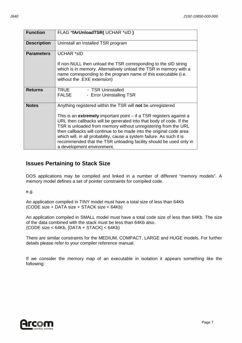
Function FLAG *fArUnloadTSR( UCHAR *sID ) Description Uninstall an installed TSR program Parameters UCHAR *sID
If non-NULL then unload the TSR corresponding to the sID string which is in memory. Alternatively unload the TSR in memory with a name corresponding to the program name of this executable (i.e. without the .EXE extension)
Returns TRUE - TSR Uninstalled
FALSE - Error Uninstalling TSR Notes Anything registered within the TSR will not be unregistered
This is an extremely important point – if a TSR registers against a URL then callbacks will be generated into that body of code. If the TSR is unloaded from memory without unregistering from the URL then callbacks will continue to be made into the original code area which will, in all probability, cause a system failure. As such it is recommended that the TSR unloading facility should be used only in a development environment.
Issues Pertaining to Stack Size DOS applications may be compiled and linked in a number of different “memory models”. A memory model defines a set of pointer constraints for compiled code. e.g. An application compiled in TINY model must have a total size of less than 64Kb (CODE size + DATA size + STACK size < 64Kb) An application compiled in SMALL model must have a total code size of less than 64Kb. The size of the data combined with the stack must be less than 64Kb also. (CODE size < 64Kb, [DATA + STACK] < 64Kb) There are similar constraints for the MEDIUM, COMPACT, LARGE and HUGE models. For further details please refer to your compiler reference manual. If we consider the memory map of an executable in isolation it appears something like the following:

CON T R OL S YS T E M S
J640 2192-10850-000-000
Page 8
TOP OF AVAILABLE APPLICATION MEMORY (TOP OF STACK)
Top of stack | Bottom of stack
The stack expands downwards as the running program makes calls to functions and/or creates ‘local’ variables. Function calls cause parameters and a return address to be placed on the stack. Local variables are also placed on the stack. The stack contracts as called functions make returns, and as this causes local variables to be discarded.
Free space
The stack expands into this free space from above. The heap (also known as the allocated data) expands into this free space from below. If we run out of free space then our stack can become corrupt and/or our data can become corrupt. This will usually cause a system failure
Top of allocated data | Bottom of allocated data
The allocated data contains all global application data. Additionally, if the application dynamically allocates near data blocks then the top of the allocated data area can grow upward into the free space. As dynamically allocated data blocks are freed the top of the allocated data area may contract (although this is dependent on issues of contiguity)
Top of program code | Bottom of program code
The program code occupies a given amount of memory and this will not change during the lifetime of any normal DOS executable.
BOTTOM OF APPLICATION MEMORY As can be seen from the above, if the stack extends down too far or the allocated data increases too much then the stack and heap areas may overlap – causing corruption and a probable system failure.
Coreleft() Function There is a Borland C++ function available which returns the amount of space between the heap and the stack during program execution. See the Borland documentation for details of coreleft() and farcoreleft() functions.
CON T R OL S YS T E M S
J640 2192-10850-000-000
Page 9
SMALL Model Executable Example For a SMALL model executable we have one area for code (the code ‘segment’) and another area for both the data and stack (data/stack segment). The maximum size of both of these segments is 64Kb. When the executable is loaded into memory the top of the stack (TOS - which also corresponds to the top of this application) is set to the top of the data/stack segement. This gives us the maximum possible space of 64Kb for data and stack. Now ordinarily this would be the best arrangement. However, when loading TSRs we must conserve as much memory as possible. The standard TOS results in a minimum requirement of 64Kb TSR memory allocation which could increase to a maximum of 128Kb with the code segment. Our stack size (as a rule of thumb) will be 4Kb or 8Kb unless we require:
• Large local (stack) data structures • Recursive functions • Floating Point Arithmetic
In the above cases the required stack size can be expected to increase.
Choice of wSPTop Parameter (when loading a TSR) The above discussion illustrates that it is useful to be able to restrict the size of the stack, which has the effect of reducing the memory requirement for a TSR. Once a TSR has been installed using fArLoadTSR() code in that TSR will only be executed as a result of a “callback” from either the TCP/IP stack or the HTTP server. The HTTP server uses it’s own internal stack. When it generates a callback to a user supplied function (see later) it switches the stack to that of the user supplied function. This new stack will be the stack in use when the function was registered (e.g. that of the executable which was shortly to become a TSR, or the user program that was running when the CGI handler was registered). At the end of the callback the stack is reset to that of the HTTP server. Given that for most TSR’s we do not require the full 64Kb segment for data and stack (in small model) we can reduce the value of the top of the stack, which is the top of the available application memory, when the callback is made. If for example, a program (which has a compiled size of say 8KBytes) is loaded using fArLoadTSR() and wSPTop is set to 0, the TSR will take up 8KBytes of memory for the program code and allocated data PLUS approximately 64KBytes (less the program’s allocated data size) for the heap and stack. For fArLoadTSR(), the wSPTop parameter directly specifies where the top of the stack should begin (in bytes above the end of the program code). Thus if we know that the stack, heap and allocated data will always take up less than 10KBytes, we could set wSPTop to 10*1024. Our stack is now ‘lower down’ and so we have less free space. It is critical to ensure that the stack will not grow down into the allocated data space at any time.

CON T R OL S YS T E M S
J640 2192-10850-000-000
Page 10
A suggested methodology is to first use either the TDUMP program or your application .MAP file to see how much application data your program uses. For details on TDUMP or mapfiles see the relevant compiler reference manual. If you use dynamic memory allocation in your application – this is not recommended for TSRs – then you should calculate how this will increase your data area usage (heap usage). Remember to take into account data fragmentation. Finally, select a value of wSPTop: wSPTop = (Total Data Usage)
+ (Worst case estimated stack usage) + (Safety margin)
If you find that your TSR application is exhibiting strange behaviours try increasing the size of wSPTop.
Choice of wSPTop Parameter (when registering CGI handler or SSI file) The wSPTop parameter in the wArSSIAddFile() and wArCGIRegister() functions is handled slightly differently from the fArLoadTSR() function discussed above. When a TSR is loaded, it has its own stack, used only by the TSR. However, a CGI handler for example, will use the same memory segment for its stack as the user program that executed the wArCGIRegister() function uses for its stack. This size of the user program stack will be dynamic and its maximum size cannot always be exactly determined, only estimated. The point in memory that the CGI handler will use as the top of its stack is determined at the moment that it is registered, not at the time of a callback. Thus at the moment a handler is registered, an estimate must be made regarding the maximum size that the user program stack might reach before a callback is made. If wSPTop is set to 0, the default top of the handler stack is set to 1000 bytes below the current user program stack pointer. This 1000 byte safety margin will work in most circumstances unless the user program has large local variable arrays or recursive functions. If a much smaller safety margin was used, there is a danger that the callback stack will be placed over existing user program stack variables, causing corruption of the user program’s local variables and/or other stack data. If a much larger safety margin was used, there might be a danger of the callback stack reaching down into the user program’s allocated memory area and corrupting that data (e.g. global variables). To increase the safety margin to 2000 bytes, for example, wSPTop should be set to “_SP - 2000” (where _SP is the current stack pointer). Alternatively, if it is easier to estimate the maximum size required of the CGI handler stack (+ the user program allocated data and heap size), then wSPTop could be set directly to that total value (+ a safety margin). Obviously the safety margin used here must be small enough to ensure that the callback stack still begins below the stack of the user program.

CON T R OL S YS T E M S
J640 2192-10850-000-000
Page 11
TSR Example The .\library\examples\chktsr directory contains a Borland C++ 4.52 project which can be used to build the TSR example application. The project builds a number of executables. These are the same source code but built in the small, medium, compact, large and huge models. It is suggested that all user TSRs are developed in small model. See CHKTSR.C for the main example code. Also see ARAPI.H, or this documentation, for details on the library APIs available. If the CHKTSRx.EXE application is run from the command line it will terminate and the code/data will stay resident in memory. This can be verified by running the DOS ‘MEM’ command with the ‘/C’ option. If the CHKTSRx.EXE is run again it will fail as there is already a TSR of the same name in memory. If the CHKTSRx.EXE is run with the ‘/u’ argument the TSR which was originally loaded into memory will now be unloaded. This can be verified using the ‘MEM’ command. NOTE: Due to the fact that any registered resources are not deregistered when the TSR is unloaded it is suggested that this facility is used only during development

CON T R OL S YS T E M S
J640 2192-10850-000-000
Page 12
SSI (“Server Side Includes”) Support Allows creation of HTML template files. These files may contain variables, defined using a certain HTML tag. When a client requests the template file it is parsed and the variable is replaced with an application definable string. This replacement string may be defined or redefined by the application at any time. This allows dynamic content to be generated simply and without the requirement to modify HTML source files. Function SINT16 wArSSIAddFile( UCHAR *pszSSIFilePath,
SINT16 (far *wfpCallback)( void ) SINT16 wSPTop )
Description Registers an HTML template file for the SSI adapter to parse Parameters UCHAR *pszSSIFilePath
Filepath to register e.g. if the parameter points to a string “ssidemo” then a client browser should request ‘http://w.x.y.z/ssidemo’ where w, x, y, z form the I.P. address of the E.I.I.A. system. SINT16 (far *wfpCallback)( void ) If this parameter is non-NULL then the specified function will be called whenever a new connection is received for the registered file-path. This allows updating of any SSI variables before the HTML template file is parsed. If this parameter is NULL then no callback is made upon receipt of a new client connection to the registered filepath SINT16 wSPTop Top of stack for callback entry. For details see Terminate and Stay Resident Support – Issues Pertaining to Stack Size. If this parameter is 0 then the default behaviour of the SSI adapter is to set the top of stack to the current top of stack minus 1000 bytes at callback time.
Returns 0 - Success
< 0 - Error condition Notes Only the last call to one of wArSSIAddFile() or wArCGIRegister() will
affect the top of stack. Prior call settings will be discarded.
CON T R OL S YS T E M S
J640 2192-10850-000-000
Page 13
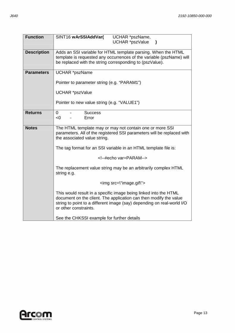
Function SINT16 wArSSIAddVar( UCHAR *pszName,
UCHAR *pszValue ) Description Adds an SSI variable for HTML template parsing. When the HTML
template is requested any occurrences of the variable (pszName) will be replaced with the string corresponding to (pszValue).
Parameters UCHAR *pszName
Pointer to parameter string (e.g. “PARAM1”) UCHAR *pszValue Pointer to new value string (e.g. “VALUE1”)
Returns 0 - Success
<0 - Error Notes The HTML template may or may not contain one or more SSI
parameters. All of the registered SSI parameters will be replaced with the associated value string. The tag format for an SSI variable in an HTML template file is:
<!--#echo var=PARAM-->
The replacement value string may be an arbitrarily complex HTML string e.g.
<img src=\"image.gif\"> This would result in a specific image being linked into the HTML document on the client. The application can then modify the value string to point to a different image (say) depending on real-world I/O or other constraints. See the CHKSSI example for further details

CON T R OL S YS T E M S
J640 2192-10850-000-000
Page 14
Function SINT16 wArSSIUpdateVar( UCHAR *pszName,
UCHAR *pszValue )
Description Updates an SSI variable for HTML template parsing – replaces the
existing value string with the new pszValue string. When the HTML template is requested any occurrences of the variable (pszName) will be replaced with the string corresponding to (pszValue).
Parameters UCHAR *pszName
Pointer to parameter string (e.g. “PARAM1”) UCHAR *pszValue Pointer to value string (e.g. “VALUE1”)
Returns 0 - Success
<0 - Error Notes The HTML template may or may not contain one or more SSI
parameters. All of the registered SSI parameters will be replaced with the associated value string. The tag format for an SSI variable in an HTML template file is:
<!--#echo var=PARAM-->
The replacement value string may be an arbitrarily complex HTML string e.g.
<img src=\"image.gif\"> This would result in a specific image being linked into the HTML document on the client. The application can then modify the value string to point to a different image (say) depending on real-world I/O or other constraints. See the CHKSSI example for further details.

CON T R OL S YS T E M S
J640 2192-10850-000-000
Page 15
Function const UCHAR *psArSSIReadVar( UCHAR *pszName) Description Returns a pointer to the value string associated with a given
parameter string. Parameters UCHAR *pszName
SSI variable name
Returns NULL - Error or NULL value
!= NULL - Pointer to value string Notes The value string should not be modified directly.
Use wArSSIUpdateVar() instead. Function void vArSSIShutdown( void) Description Shuts down SSI adaptor: unhooks HTTP server
Parameters None Returns Nothing Notes This must be called before the application is unloaded from memory
An Example SSI Implementation Server side includes are about the simplest way to insert dynamic content into HTML files which are then served to one or more clients. The application developer decides upon a number of variables which may, for example, describe the state of various system components. e.g. We might decide to use four variables to describe the state of four LEDs. Each of these variables must be given a name – the “Parameter string” e,g, LED1, LED2, LED3, LED4 A minimal HTML template file must now be generated, using any text editor.

CON T R OL S YS T E M S
J640 2192-10850-000-000
Page 16
The simplest case would be something like the following: <HTML> <BODY> LED1 = <!--#echo var=”LED1”--> </BODY> </HTML> Note the very specific tag containing the LED1 parameter. This is the standard SSI variable replacement format. Having created the HTML template and stored this on the server, the next step is to “register” this template file with the SSI adaptor. An example program is given in the .\examples\chkssi directory. The part of the code which registers the HTML file is: if(wArSSIAddFile("ssitest1.sht", wArUpdateVars, SP_TOP) < 0) { printf("Error: Adding SSI file: %s\n", "ssitest1.sht"); return(-1); } NOTE :The HTTP server (HTTPD) must be resident for this registration to succeed Now, whenever a client requests a URL of the form http://w.x.y.z/ssitest1.sht the SSI adaptor will parse the ssitest1.sht file on the filesystem and replace any registered variables before transmitting the file to the client. The application developer must ensure that the variables are also registered: if(wArSSIAddVar(“LED1”,”ON”) < 0) { printf("Error: Adding SSI variable: %s\n", “LED1”); return(-1); } With both the HTML template file and the appropriate variables registered a request for the http://w.x.y.z/ssitest1.sht file will result in the following being sent to the client: <HTML> <BODY> LED1 = ON </BODY> </HTML>

CON T R OL S YS T E M S
J640 2192-10850-000-000
Page 17
Dynamic SSI Variable Update Looking back at the wArSSIAddFile() code snippet we see that there is a function referenced, wArUpdateVars(). This function will be called whenever a client connects to the HTTP server and requests the registered file. The application developer may choose to implement this function to update all SSI variables before the HTML template file is parsed. Alternatively a NULL may be passed here in which case no callback is made. NOTE: For details on the correct choice of the SP_TOP parameter see: TSR (“Terminate and Stay Resident”) Support -> Choice of wSPTop Parameter

CON T R OL S YS T E M S
J640 2192-10850-000-000
Page 18
CGI (“Common Gateway Interface”) Support Allows the execution of user application code when specified URL requests are received from clients. Additionally supports the parsing of data received from these clients. Returned data may be in the form of dynamic HTML or other depending on application requirements. Function SINT16 wArCGIRegister ( UCHAR *pszFilePath,
CGI_HANDLERS far *pCgi, SINT16 wSPTop )
Description Registers a partial URL path to the CGI adapter Parameters UCHAR *pszFilePath
URL portion to register with HTTP server e.g. “cgidemo”. A client would then query http://w.x.y.z/cgidemo CGI_HANDLERS far *pCgi Pointer to a CGI_HANDLERS structure. This structure defines all possible user callbacks during a client connection. See the CGI_HANDLERS structure below for details. SINT16 wSPTop Top of stack for callback entry. For details see Terminate and Stay Resident Support – Issues Pertaining to Stack Size. If this parameter is 0 then the default behaviour of the CGI adapter is to set the top of stack to the current top of stack minus 1000 bytes at callback time.
Returns 0 - Success
< 0 - Error condition Notes Only the last call to one of wArSSIAddFile() or wArCGIRegister() will
affect the top of stack. Prior call settings will be discarded
CON T R OL S YS T E M S
J640 2192-10850-000-000
Page 19
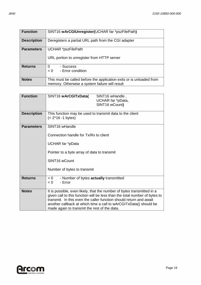
Function SINT16 wArCGIUnregister( UCHAR far *pszFilePath) Description Deregisters a partial URL path from the CGI adapter Parameters UCHAR *pszFilePath
URL portion to unregister from HTTP server
Returns 0 - Success
< 0 - Error condition Notes This must be called before the application exits or is unloaded from
memory. Otherwise a system failure will result Function SINT16 wArCGITxData( SINT16 wHandle ,
UCHAR far *pData, SINT16 wCount)
Description This function may be used to transmit data to the client
(< 2^16 -1 bytes) Parameters SINT16 wHandle
Connection handle for Tx/Rx to client UCHAR far *pData Pointer to a byte array of data to transmit SINT16 wCount Number of bytes to transmit
Returns > 0 - Number of bytes actually transmitted
< 0 - Error Notes It is possible, even likely, that the number of bytes transmitted in a
given call to this function will be less than the total number of bytes to transmit. In this even the caller function should return and await another callback at which time a call to wArCGITxData() should be made again to transmit the rest of the data.

CON T R OL S YS T E M S
J640 2192-10850-000-000
Page 20
Function SINT16 wArCGIRxData( SINT16 wHandle ,
UCHAR far *pData, SINT16 wSize )
Description This function may be used to receive data from the client
(< 2^16 -1 bytes) e.g. sent via a POST function Parameters SINT16 wHandle
Connection handle for Tx/Rx from client UCHAR far *pData Pointer to a byte array of data to hold received data SINT16 wCount Size of buffer
Returns > 0 - Number of bytes actually received
< 0 - Error Notes It is possible, even likely, that the number of bytes received in a given
call to this function will be less than the total number of bytes expected from the client. In this even the caller function should return and await another callback at which time a call to wArCGIRxData() should be made again to receive more data.

CON T R OL S YS T E M S
J640 2192-10850-000-000
Page 21
Function SINT16 wArCGIParseQuery( UCHAR far *pParam,
SINT16 wSize, UCHAR far **pValue, UCHAR far **pNextParam )
Description Parses through a subsection of a query.
Query form: "Axx=ABCD&Byy=1234" etc. Caller's pValue and pNextParam get set to the appropriate portion of the query. pNextParam set to NULL if no next parameter
Parameters UCHAR far *pParam
Start of a parameter in the query string SINT16 wSize Size of query string UCHAR far * far *pValue Pointer to a pointer to this parameter value (set on return) UCHAR far * far *pNextParam Pointer to a pointer to the next parameter (set on return)
Returns SUCCESS - There are more parameters to handle
-1 - Parse error Notes On return parameters and values are NULL terminated
e.g. "P1=V1&P2=V2" => "P1_V1_P2_V2" where _ is NULL pValue may be NULL if query has a form of "PARAMETER1&PARAMETER2=VALUE2"

CON T R OL S YS T E M S
J640 2192-10850-000-000
Page 22
Function SINT16 wArCGIParsePOSTParams(
UCHAR far *pParam, SINT16 wSize, UCHAR far * far *pValue, UCHAR far * far *pNextParam)
Description Parses through a subsection of a POST for parameters.
Post form: "P1=V1\0x0D\0x0A" etc. Caller's pValue and pNextParam get set to the appropriate portion of the query. pNextParam set to NULL if no next parameter
Parameters UCHAR far *pParam
Start of a parameter in the query string SINT16 wSize Size of query string UCHAR far * far *pValue Pointer to a pointer to this parameter value (set on return) UCHAR far * far *pNextParam Pointer to a pointer to the next parameter (set on return)
Returns > 0 - The number of parsed characters
-1 - Parse error Notes On return parameters and values are NULL terminated
e.g. "P1=V1\0x0D\0x0AP2=V2" => "P1_V1__P2_V2" where _ is NULL pValue may be NULL if query has a form of "PARAMETER1\0x0D\0x0APARAMETER2=VALUE2" This parser does not handle multiple line values i.e. use of the <TEXTAREA> tag will cause the parsing to break.
CON T R OL S YS T E M S
J640 2192-10850-000-000
Page 23
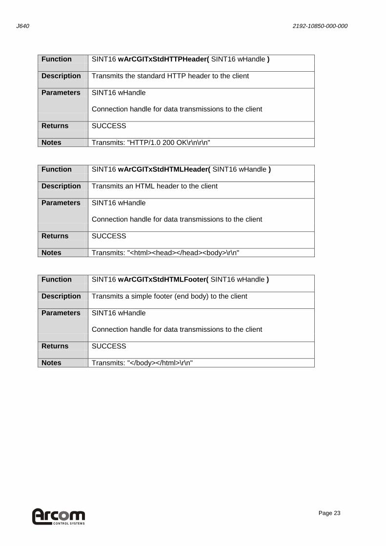
Function SINT16 wArCGITxStdHTTPHeader( SINT16 wHandle ) Description Transmits the standard HTTP header to the client Parameters SINT16 wHandle
Connection handle for data transmissions to the client
Returns SUCCESS Notes Transmits: "HTTP/1.0 200 OK\r\n\r\n" Function SINT16 wArCGITxStdHTMLHeader( SINT16 wHandle ) Description Transmits an HTML header to the client Parameters SINT16 wHandle
Connection handle for data transmissions to the client
Returns SUCCESS Notes Transmits: "<html><head></head><body>\r\n" Function SINT16 wArCGITxStdHTMLFooter( SINT16 wHandle ) Description Transmits a simple footer (end body) to the client Parameters SINT16 wHandle
Connection handle for data transmissions to the client
Returns SUCCESS Notes Transmits: "</body></html>\r\n"

CON T R OL S YS T E M S
J640 2192-10850-000-000
Page 24
Structure CGI_HANDLERS Function CGI_HANDLERS->
SINT16 (far *wfpConnected )( SINT16 wHandle ) Description Initial connect handler
Called when a client connects to the HTTP serve. Allows user to return HTTP, HTML headers (or custom data). This is called prior to the parameters on the GET line being parsed.
Parameters SINT16 wHandle
Handle for this connection. Used to Tx/Rx data.
Returns SUCCESS - Successful
!= SUCCESS - Error
Notes If the handler is NULL a standard HTTP response header is sent (no
HTML header is sent)

CON T R OL S YS T E M S
J640 2192-10850-000-000
Page 25
Function CGI_HANDLERS->
SINT16 (far *wfpGetParam)( SINT16 wHandle, UCHAR far *pParam, UCHAR far *pValue )
Description User parameter handler
Called when a client connects to the HTTP server and provides parameters via the get method. e.g. http://w.x.y.z/cgi?alex=1&says=2&hello=3 would result in three separate calls to this handler.
Parameters SINT16 wHandle
Handle for this connection. Used to Tx/Rx data UCHAR far *pParam Pointer to a parameter string for this variable UCHAR far *pValue Pointer to a value string for this variable
Returns SUCCESS - Successful
!= SUCCESS - Error Notes If the handler is NULL, data provided with the URL is not parsed.
CON T R OL S YS T E M S
J640 2192-10850-000-000
Page 26
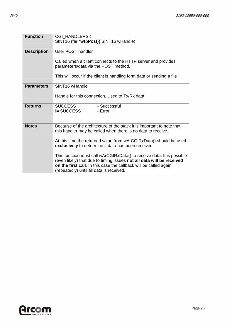
Function CGI_HANDLERS->
SINT16 (far *wfpPost)( SINT16 wHandle) Description User POST handler
Called when a client connects to the HTTP server and provides parameters/data via the POST method. This will occur if the client is handling form data or sending a file
Parameters SINT16 wHandle
Handle for this connection. Used to Tx/Rx data
Returns SUCCESS - Successful
!= SUCCESS - Error
Notes Because of the architecture of the stack it is important to note that
this handler may be called when there is no data to receive. At this time the returned value from wArCGIRxData() should be used exclusively to determine if data has been received. This function must call wArCGIRxData() to receive data. It is possible (even likely) that due to timing issues not all data will be received on the first call . In this case the callback will be called again (repeatedly) until all data is received.

CON T R OL S YS T E M S
J640 2192-10850-000-000
Page 27
Function CGI_HANDLERS->
SINT16 (far *wfpTxData )( SINT16 wHandle, SINT16 wTxCount) Description User Transmit handler
Called when a client connects to the HTTP server after the GET and/or POST data has been handled, if such data is present. The purpose of this handler is to allow dynamic data transmission from the server to the client.
Parameters SINT16 wHandle
Handle for this connection. Used to Tx/Rx data SINT16 wTxCount Number of Tx characters which can be transmitted
Returns > 0 - Not done with transmit (more data to transmit)
= 0 - Done with transmit < 0 - Error
Notes Function CGI_HANDLERS->
SINT16 (far *wfpPreDisconnect )( SINT16 wHandle ) Description User Transmit handler
Called when all user data has been sent to client just prior to disconnection. A user handler can transmit footer information or an HTML closure tag as a minimum. This is not sent through the wfpTxData() function
Parameters SINT16 wHandle
Handle for this connection. Used to Tx/Rx data
Returns SUCCESS - All OK
!= SUCCESS - Error Notes

CON T R OL S YS T E M S
J640 2192-10850-000-000
Page 28
Common Gateway Interface Demonstration Applications The CGI implementation is more complex to use than SSI but provides a more flexible development environment. It is possible to analyse data provided by the client (through the ‘GET’ and ‘POST’ methods). It is also possible to generate completely dynamic pages of HTML data, or alternatively to provide dynamic binary information. The .\examples\chkcgi application demonstrates a simple CGI implementation: The first step is to create a CGI_HANDLERS structure. This structure contains the addresses of functions which will be called when a client connects to a registered URL on the HTTP server. CGI_HANDLERS CGIHandlers = { wArDoHeader, // The wfpConnected() handler - see ArApi.h wArGetParam, // The wfpGetParam() handler - ditto wArGetPost, // The wfpPost() handler wArTxData, // The wfpTxData() handler wArDoFooter, // The wfpPreDisconnect handler }; These function types are documented in .\include\ArAPI.h: wfpConnected() This function will be called when a client connects to a registered URL The user may respond with the standard HTTP header and the standard HTML header. wfpConnected() will be called once and once only per connection. wfpGetParam() This function will be called if a client provides parameter/value sets on the command line. For details see ARAPI.H and CHKCGI.C. wfpConnected() will be called once per parameter/value set provided on the client URL string. e.g. http://w.x.y.z/cgidemo?param1¶m2=value2¶m3=value3 This would result in 3 calls to the wfpGetParam() callback with the following parameters:
pParam => “param1”, pValue => NULL pParam => “param2”, pValue => “value2” pParam => “param3”, pValue => “value3” wfpPost() This function will be called if a client provides information via the POST method. This is a standard way of providing form data to a server. wfpPost() will be called if the client provides data via the POST method.

CON T R OL S YS T E M S
J640 2192-10850-000-000
Page 29
NOTE: It is extremely important to understand that the callback may be called before all of the POSTed data is received. It should not be assumed that any complete data structures are in memory when a given callback occurs. The user provided function may be called more than once as data is received. It should also be assumed that the callback can occur when no new data has been received (due to stack constraints).
wfpTxData() This function will be called regardless of whether the client has provided data via the POST or the GET methods. The user may transmit any necessary data to the client (although this does not preclude transmission of data in the other callback functions). NOTE: It is extremely important to understand that it may not be possible to transmit all data during one call to the callback. In this case the wArCGITxData() function will return a value indicating the number of bytes actually sent, referenced to the start of the string provided. If all data has not been sent the wfpTxData() function should return a value greater than zero (e.g. the number of bytes still to transmit). In this case the function will be called again to transmit more data to the client. If all data has been sent the wfpTxData() function should return a zero. If a zero is returned the function will not be called again during this connection. wfpPreDisconnect() This function is called just prior to disconnecting from the client. The user may transmit an HTML closure tag if required wfpPreDisconnect() will be called once and once only per connection Any of these functions may be set to a NULL address within the CGI_HANDLERS structure. In this case the relevant function will simply not be called. In the case of the wfpConnected() and wfpPreDisconnect() functions, standard HTTP and HTML headers and footers will be sent to the client. Again, is it important to have read the callback registration stack constraints section (TSR Support Section) when dealing with callbacks.
Stack Overflow Example The .\library\examples\chkstack directory contains a Borland C++ 4.52 project which can be used to build the stack overflow example application. This application sets the callback stack incorrectly (with respect to the operation of the application). The callback stack is set to 1000 bytes below the standard application stack (the default behaviour at registration time). Then 2000 bytes of data is placed onto the application stack and the application loops until a key is pressed. When a client connects to the http://w.x.y.z/stackcheck URL the callback executes which results in the standard application stack becoming corrupt. This application is included to clarify the issues involved in choosing the callback stack size.

CON T R OL S YS T E M S
J640 2192-10850-000-000
Page 30
Embedded LAN Connections
TCP/IP Servers The FTPD and HTTPD servers are included in the MERLIN AUTOEXEC.BAT file pre-loaded on the MERLIN and are run at startup.
FTP You can FTP into the MERLIN from your host by typing (in a DOS window): FTP 10.2.6.14 (where 10.2.6.14 is the I.P. address of the MERLIN) You should then log on as ‘su’ with password ‘su’ for full access privileges.
HTTP Entering http://10.2.6.14 (where 10.2.6.14 is the I.P. of the MERLIN) within your browser on the host will bring up the default ‘index.htm’ page on the MERLIN. See the Datalight SOCKETS.PDF documentation supplied on the CD for further details.
NETBIOS/SMB Support The Datalight Sockets TCP/IP stack contains an executable called NETBIOS.COM. This provides an API for remote access to files on remotely networked machines. However, the NETBIOS API is not sufficient to access these files by itself. An additional application component is required to provide the drive level redirection. The ‘PowerLAN’ freeware product from Bay Networks (http://www.perftech.com) provides this functionality. We have provided a number of executables from this application suite to facilitate connectivity of SMB to Windows, Sockets and Linux systems. These include: SERVER Provides remote access to
local drives REDIR Provides local access to
remote drives NET Allows the user to configure
access to remote drives
Configuring the MERLIN to access a remote Windows 9x drive over Ethernet Copy the following files from the development kit CD to the MERLIN: SHARE.EXE (located in ..\Merlin\Romdos) NETBIOS.COM (located in ..\Merlin\Sockets\Apps\Netbios) REDIR.EXE (located in ..\Merlin\Utils\PowerLAN\Sw\Programs) NET.EXE (located in ..\Merlin\Utils\PowerLAN\Sw\Programs)

CON T R OL S YS T E M S
J640 2192-10850-000-000
Page 31
On the MERLIN target board, run the SHARE command to enable DOS level file sharing. Run the NETBIOS.COM command to enable the NETBIOS API. Run the REDIR.EXE command to provide local access to remote drives. Then type: NET USE E: \\ server\drive where: server is the Windows 9x name of your host PC (or another networked PC) drive is the name of the shared network drive. A success message should be displayed. This command will map the networked drive to drive E: of the MERLIN. You may need to modify the MERLIN’s CONFIG.SYS file to change the LASTDRIVE parameter to allow E: to be allocated. Type NET USE /? a t the command line or read PLDOSIN.DOC (in the PowerLAN\reference directory) for further details.
NETBIOS / SMB Troubleshooter • Check that the name of the Windows system is as expected (Control Panel->Networking-
>Identification)
• Check that the drive/directory is shared under the correct name
• Check that the NETBIOS/NETBEUI protocol is present in your server TCP/IP settings
• Try a shorter share name e.g. < 8 characters.
• Try connecting to the share from another Windows system.
Connecting the MERLIN to a Modem
Configuring the MERLIN for Modem Operation On the host PC open a DOS window and run the SETSOCK.EXE utility (located on the development kit CD in ..\Merlin\Utils). When prompted, select modem and then ‘dial-in ’, ‘dial-out’ or ‘dial-in and dial-out ’ as appropriate. Select ‘Non standard port ’ and enter the IO address as 0x3E8 (COM3) and the interrupt as IRQ1. For dial-in networking (or dial-in and dial-out):
• Enter an I.P. address for the target system to use when the host system dials in.
• Next enter a user name and a password to authenticate the incoming connection.
CON T R OL S YS T E M S
J640 2192-10850-000-000
Page 32
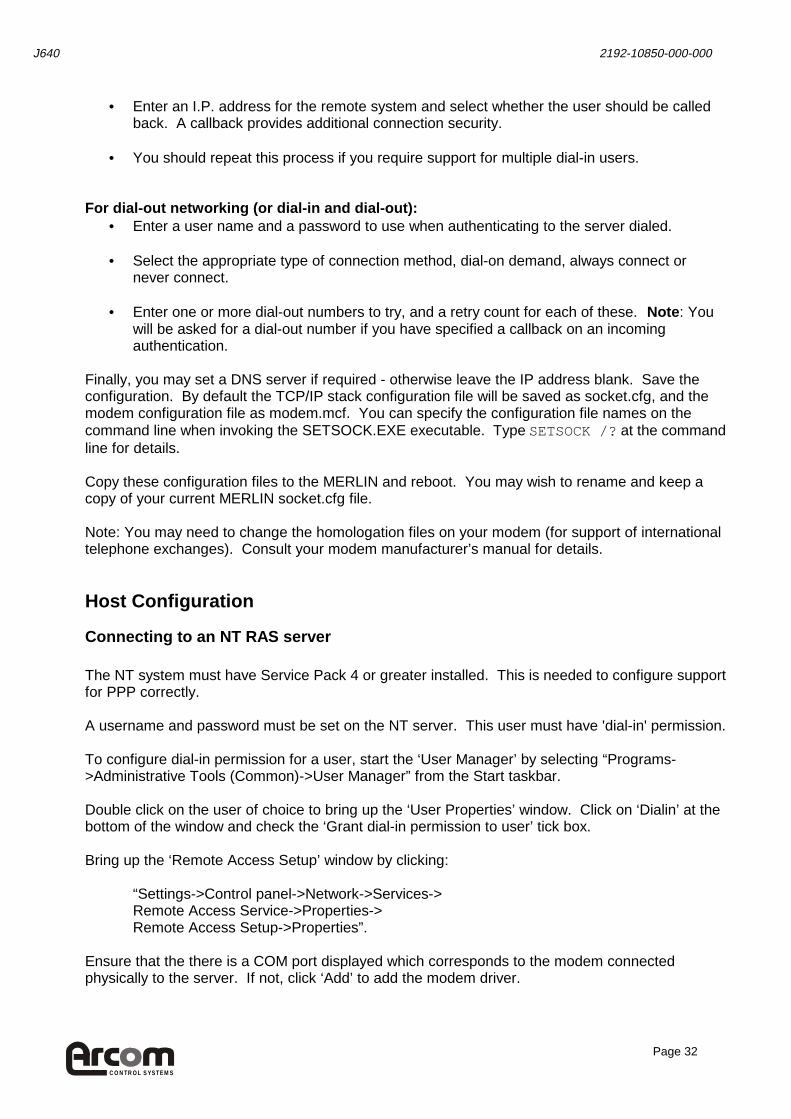
• Enter an I.P. address for the remote system and select whether the user should be called back. A callback provides additional connection security.
• You should repeat this process if you require support for multiple dial-in users.
For dial-out networking (or dial-in and dial-out):
• Enter a user name and a password to use when authenticating to the server dialed.
• Select the appropriate type of connection method, dial-on demand, always connect or never connect.
• Enter one or more dial-out numbers to try, and a retry count for each of these. Note : You
will be asked for a dial-out number if you have specified a callback on an incoming authentication.
Finally, you may set a DNS server if required - otherwise leave the IP address blank. Save the configuration. By default the TCP/IP stack configuration file will be saved as socket.cfg, and the modem configuration file as modem.mcf. You can specify the configuration file names on the command line when invoking the SETSOCK.EXE executable. Type SETSOCK /? at the command line for details. Copy these configuration files to the MERLIN and reboot. You may wish to rename and keep a copy of your current MERLIN socket.cfg file. Note: You may need to change the homologation files on your modem (for support of international telephone exchanges). Consult your modem manufacturer’s manual for details.
Host Configuration
Connecting to an NT RAS server The NT system must have Service Pack 4 or greater installed. This is needed to configure support for PPP correctly. A username and password must be set on the NT server. This user must have 'dial-in' permission. To configure dial-in permission for a user, start the ‘User Manager’ by selecting “Programs->Administrative Tools (Common)->User Manager” from the Start taskbar. Double click on the user of choice to bring up the ‘User Properties’ window. Click on ‘Dialin’ at the bottom of the window and check the ‘Grant dial-in permission to user’ tick box. Bring up the ‘Remote Access Setup’ window by clicking:
“Settings->Control panel->Network->Services-> Remote Access Service->Properties-> Remote Access Setup->Properties”.
Ensure that the there is a COM port displayed which corresponds to the modem connected physically to the server. If not, click ‘Add’ to add the modem driver.

CON T R OL S YS T E M S
J640 2192-10850-000-000
Page 33
Click on ‘Configure’ to bring up the ‘Configure port usage’ window. Select ‘Dial out and receive calls’ or ‘Receive calls only’. This will allow incoming calls to be picked up. Click ‘Network’ to bring up the ‘Network Configuration’ window. Ensure that the Server Settings TCP/IP box is checked and click ‘Configure’ to configure TCP/IP support. If you have a DHCP server on your network you may wish to use this to configure the target I.P. address when it dials-in. Alternatively you should specify a range of I.P. addresses to assign to clients e.g. Begin 192.1.1.10, End 192.1.1.20 will allow 10 I.P. addresses in that range to be assigned to clients. You may also allow clients to request a specific I.P. address by checking the box at the bottom of the TCP/IP configuration window. Finally, you should click “Allow any authentication including clear text” in the “Network configuration” window. This is needed for the PAP connection authentication implemented in the TCP/IP stack. Click ‘Continue’ to store the new settings. You may need to restart the server at this point. To ensure that the ‘Remote Access’ service is running, select “Programs->Administrative Tools (Common)->Remote Access Admin” from the Start taskbar. If the service is not running click on ‘Server->Start Remote Access Service” and leave the name of the server set to the default. This will result in the RAS service starting. If you click on the server name listed in the RAS window, the communication ports available for dial-in are listed. If you then click on the relevant serial port you will be shown the port status window. This window is useful for tracking the state of incoming connections. You can now initiate a connection from the client, for example by typing: XPING [Server I.P. Address]. IPSTAT on the E.I.I.A will give the I.P. address when connected. IPCONFIG on the Windows NT system will give the NT I.P. address.
Connecting to a Windows 9x system Ensure that the ‘Dial-up Networking component of Windows is installed. To check this, open “Settings->Control Panel->Add / Remove Programs” and select the “Windows Setup” tab. Double-click on the “Communications” line in the Components window. If “Dial-Up Networking” is not ticked you should tick it and press “OK”. Follow the instructions to install dial-up networking support. In Windows 98 you should also check the “Dial-Up Server” component to install dial-in support. Ensure that your modem is correctly configured and that the TCP/IP protocol is installed and bound to the modem. To install a modem use the wizard located at “Settings->Control Panel->Modems”. You will need to restart your system after installing a new modem. To install TCP/IP support you should select “Settings->Control Panel->Network”. If there is no “TCP/IP -> Dial-Up Adapter” line in this window then you should install TCP/IP for the adapter: one of the lines in the “Network Components” window will display “Dial-Up adaptor”. Click on this line to select and click the “Add” button.

CON T R OL S YS T E M S
J640 2192-10850-000-000
Page 34
Next select the “Protocol” network component type and “Microsoft” for the manufacturer. The “TCP/IP” protocol will appear in the “Network Protocols” window. You should double click on this line. A new line will now appear in the “Network components” window, “TCP/IP -> Dial-Up Adapter”. Click ‘OK’. The operating system will now install a number of files. You will need to restart the system. Select the “Programs->Accessories->Dial-Up Networking” menu item (“Programs->Accessories->Communications->Dial-Up Networking” under Windows 98). This will start the “Dial-Up Networking” wizard. The wizard allows you to create dial-out connections. You may create a connection if you wish – it is important that after a connection has been created, you right click on it and select “Properties”. Click on “Configure” in the “Connect Using” section of the connection properties window. This will bring up a window with three tabs. Click on the “Server Types” tab and deselect the “Require encrypted password” box if it is ticked. You may also wish to specify TCP/IP settings to set the I.P. address of the Windows 9x system specifically. For dial-in support, Select “Programs->Accessories->Dial-Up Networking” (“Programs->Accessories->Communications->Dial-Up Networking” under Windows 98) and click the “Connections” menu, and then click “Dial-Up Server”. NOTE: If you are running Windows 95 ensure that the Windows 95 Microsoft Plus! Pack is installed. This provides the Dial-Up server functionality. For details see: http://www.microsoft.com/TechNet/win95/technote/remote.asp
If you need to upgrade your Dial-Up networking support you should visit the Microsoft Windows 95 web site. The current link for the download is: http://microsoft.com/ntserver/nts2/downloads/recommended/dun13win95/default.asp In the Dial-Up Server dialog box, click Allow Caller Access. This dialog box will look different depending on whether you have enabled user-level or share-level security for the computer. Optionally, click Change Password to define a call-in password for Dial-Up Networking clients, and then click OK. Alternatively, if you are using user-level security for peer resource sharing, select the users who have access to this dial-up server. Then click OK. Click the Server Type button and ensure the default server type is selected. This starts the server in PPP mode. Deselect “Require encrypted password” as the E.I.I.A. supports the password authentication protocol (P.A.P.) only, and does not support password encryption. Click OK, and the dial-up server will be ready to answer incoming calls. You can now initiate a connection from the client, for example by typing: XPING [Server I.P. Address]. IPSTAT on the E.I.I.A will give the I.P. address when connected. IPCONFIG on the Windows NT system will give the NT I.P. address

CON T R OL S YS T E M S
J640 2192-10850-000-000
Page 35
Modem Connectivity Troubleshooter
• Make sure all cables are properly connected and modem power is on.
• Make sure modem is connected to correct COM port.
• Make sure the same username and password combination is specified on both target and host systems.
• Windows 9x - Check the modem is correctly configured by going to Control Panel-
>Modems->Diagnostics. The name of the modem should be displayed by the correct communications port and the ‘More Info’ button should provide information about the modem rather than displaying an error message.
• Windows 9x – Chapter 28 of the Windows 95 Resource kit deals with Dial-Up Networking
and Mobile Computing. This can be found at: http://msdn.microsoft.com/library/default.asp?URL=/library/winresource/dnwin95/s7260.htm For further details consult your Network Administration team and/or search the Microsoft knowledge base at: http://msdn.microsoft.com/
Direct RS232 Cable Connection
Connect the MERLIN COM3 port to a serial port on the host PC using a null-modem serial cable. You will probably still want to use the one supplied in the development kit to connect to the MERLIN console port (default = COM1).
MERLIN Configuration For connection to a Windows system, run SETSOCK.EXE from a DOS window on the host PC and select “Direct Cable Connection to Windows”. Alternatively, for Linux or other OS select “Direct Cable Connection to any other OS” Select the method of connection, dial-in, dial-out or both. Enter the serial communications port you are using. Next, you should specify a user name and password corresponding to any dial-out connection you wish to make; this user must be configured on the target system. If required you may set an I.P address that you wish to use when dialing out – if this is set to 0.0.0.0 the host will be expected to set the I.P. address. Select “Always connect”. If you wish to support dial-in networking you should now enter user names, passwords and I.P. addresses corresponding to those users you wish to allow to dial in. If you know the I.P address of your DNS server enter it next, or press return.

CON T R OL S YS T E M S
J640 2192-10850-000-000
Page 36
Save the configuration and copy to the MERLIN. Reboot the MERLIN to load the TCP/IP stack with the new parameters
Host Configuration
Connection to a Windows NT system The NT server must have Remote Access Services (RAS) enabled and you must be running Service Pack 4 or greater. A username and password must be set on the NT server. This user must have 'dial-in' permission. To configure dial-in permission for a user, start the ‘User Manager’ by selecting “Programs->Administrative Tools (Common)->User Manager” from the Start taskbar. Double click on the user of choice to bring up the ‘User Properties’ window. Click on ‘Dialin’ at the bottom of the window and check the ‘Grant dial-in permission to user’ tickbox. Also the "Direct Serial cable between two PCs " modem driver must be installed on the relevant communications port. To install the "Direct Serial cable between two PCs ", select “Settings->Control Panel->Modems” and click on “Add”. Check the “Do not detect my modem…” box and select “(Standard Modem Types)”, which will then allow you to select “Dial-Up Networking Serial Cable between 2 PCs”. Click “Next”. Choose the COM port you require to connect with, click “Next” and then “Finish”. The Remote Access Services will now be reconfigured. You will be presented with the “Remote Access Setup” window. Alternatively this window can be accessed from “Settings->Control panel->Network->Services->Remote Access Service->Properties->Remote Access Setup->Properties”. Click “Add” and add the COM port, which you configured for direct connection. Click “Configure” and enable the device to “Receive calls”. You must also click “Network” and make sure that the “Encryption Settings” are for “Allow any authentication including clear text”. Make sure the TCP/IP protocol is checked and add a range of I.P. addresses to use for incoming connections. e.g. set begin to 192.1.1.10 and end to 192.1.1.20, say. You will need to restart the system. To ensure that the ‘Remote Access’ service is running, select “Programs->Administrative Tools (Common)->Remote Access Admin” from the Start taskbar. If the service is not running click on ‘Server->Start Remote Access Service” and leave the name of the server set to the default. This will result in the RAS service starting. If you click on the server name listed in the RAS window, the communication ports available for dial-in are listed. If you then click on the relevant serial port you will be shown the port status window. This window is useful for tracking the state of incoming connections.

CON T R OL S YS T E M S
J640 2192-10850-000-000
Page 37
You can now initiate a connection from the client, for example by typing: XPING [Server I.P. Address]. IPSTAT on the E.I.I.A will give the I.P. address when connected. IPCONFIG on the Windows NT system will give the NT I.P. address.
Connecting from a Windows 9x system NOTE: If you are running Windows 95 ensure that the Windows 95 Microsoft Plus! Pack is installed. This provides the Dial-Up server functionality. For details see: http://www.microsoft.com/TechNet/win95/technote/remote.asp If you need to upgrade your Dial-Up networking support you should visit the Microsoft Windows 95 web site. The current link for the download is: http://microsoft.com/ntserver/nts2/downloads/recommended/dun13win95/default.asp For Windows 95 and 98 you will be required to install a null modem driver for connection of two PC’s. Arcom recommend the freely available Aeriden drivers included on this CD in Utils\Aeriden To install the Null Modem driver follow these steps: 1. Open the Control Panel. 2. Open Network. 3. Make sure the Dial-Up Adapter is installed and bound to a protocol (such as TCP/IP, IPX/SPX or Netbeui). 4. Open the Control Panel. 5. Open Modems. 6. Click on the Add button. 7. Check Don’t Detect My Modem. Click on the Next button. 8. Click on Have Disk. 9. Click on Browse to select mdmai.inf. 10. Select the manufacturer Aeriden. For the model, select Direct Connection. You should now restart your system. Ensure that the null modem driver baud rate is increased from the 19200 default to a more reasonable 57600 (Double–click on “Settings->Control Panel->Modems”. Select the “Direct Connection” line and click properties. You may now increase “Maximum Speed” to “57600”. Dial-in networking may now be set up as detailed in the “Modem” section earlier in this Quickstart manual.
Direct Cable Connectivity Troubleshooter
• Make sure you are using a crossover (null modem) cable. Check that pin connections are 3-2, 2-3, 5-5.

CON T R OL S YS T E M S
J640 2192-10850-000-000
Page 38
Glossary API Application Programming Interface
ARP Address Resolution Protocol. Converts I.P. addresses to MAC (Ethernet)
Addresses for TCP/IP connections to be established between hosts. Authentication The process whereby a server identifies that a client is allowed to connect and
determines what access that client should have. BOOTP Boot Protocol. A BOOTP server runs somewhere on the network. Devices
powering up request an I.P. address and possibly boot image location from the server. Largely superceded by DHCP.
Browser An HTML enabled client with connectivity to an intranet or the Internet. Displays HTML files and often includes 'plug-ins’ to support other media types.
CGI Common Gateway Interface. A specification for transfer of information between an HTTP client (browser) and an HTTP server (Web server). Also specifies how a server should make the information available to a user application. This is a powerful and flexible way of dealing with user input and providing dynamic content creation programmatically. e.g. If a user fills in a form on a browser and the form information is sent to the web server, the server must then send the information to a custom application for processing. The custom application will then generate HTML content, as a minimum, which must be returned to the browser for display.
Callback A method of improving dial-up connectivity security. A host dials up an embedded target. The host then authenticates to the target. For certain hosts the target disconnects immediately and dials a pre-configured number, reconnecting back to the host. In this way you ensure that the target is connected to a known point.
DHCP Dynamic Host Configuration Protocol. Successor to BOOTP. A DHCP server runs somewhere on the network. Devices powering up request an I.P. address and possibly a boot image location from the server. The I.P. address is ‘leased’ to the client for a set period of time. This attempts to minimise address space usage.
DNS Domain Name System. A DNS server converts domain names (e.g. arcomcontrols.com) to I.P. addresses with which TCP/IP enabled hosts can communicate. A client must have the I.P. address of an appropriately configured DNS server to support connectivity using domain names.
EIIA Embedded Industrial Internet Appliance. Firewall A set of applications, usually running on a 'gateway' server with the intention of
protecting resources on an intranet from external tampering. A firewall screens incoming and outgoing requests before determining whether to allow connections.
FTP File Transfer Protocol. A protocol designed for the transmission of files from client to server or vice-versa. Usually an interactive process although this can be automated.
Gateway A network point (often a dedicated machine), which provides an entrance point to another network. A gateway often acts as a ‘router’ in that it knows how to ‘route’ packets of information from one network to another.
HTTP HyperText Transfer Protocol. The protocol widely used on the Internet for transferring files from an HTTP server to a client. The client is usually, although not always, an HTML browser.
HTML HyperText Markup Language. The language used to create Hypertext documents. HTML is a markup language meaning that contents is defined in the documents but specific formatting is left to the HTML client (browser).
CON T R OL S YS T E M S
J640 2192-10850-000-000
Page 39
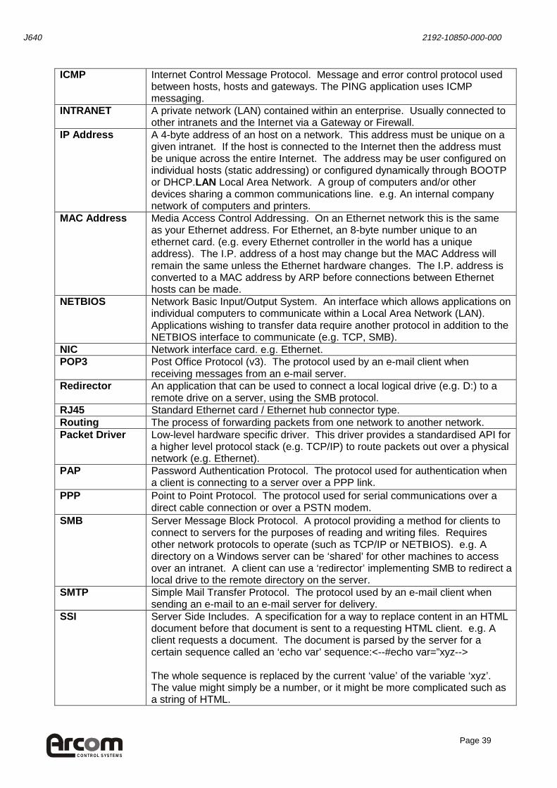
ICMP Internet Control Message Protocol. Message and error control protocol used between hosts, hosts and gateways. The PING application uses ICMP messaging.
INTRANET A private network (LAN) contained within an enterprise. Usually connected to other intranets and the Internet via a Gateway or Firewall.
IP Address A 4-byte address of an host on a network. This address must be unique on a given intranet. If the host is connected to the Internet then the address must be unique across the entire Internet. The address may be user configured on individual hosts (static addressing) or configured dynamically through BOOTP or DHCP.LAN Local Area Network. A group of computers and/or other devices sharing a common communications line. e.g. An internal company network of computers and printers.
MAC Address Media Access Control Addressing. On an Ethernet network this is the same as your Ethernet address. For Ethernet, an 8-byte number unique to an ethernet card. (e.g. every Ethernet controller in the world has a unique address). The I.P. address of a host may change but the MAC Address will remain the same unless the Ethernet hardware changes. The I.P. address is converted to a MAC address by ARP before connections between Ethernet hosts can be made.
NETBIOS Network Basic Input/Output System. An interface which allows applications on individual computers to communicate within a Local Area Network (LAN). Applications wishing to transfer data require another protocol in addition to the NETBIOS interface to communicate (e.g. TCP, SMB).
NIC Network interface card. e.g. Ethernet. POP3 Post Office Protocol (v3). The protocol used by an e-mail client when
receiving messages from an e-mail server. Redirector An application that can be used to connect a local logical drive (e.g. D:) to a
remote drive on a server, using the SMB protocol. RJ45 Standard Ethernet card / Ethernet hub connector type. Routing The process of forwarding packets from one network to another network. Packet Driver Low-level hardware specific driver. This driver provides a standardised API for
a higher level protocol stack (e.g. TCP/IP) to route packets out over a physical network (e.g. Ethernet).
PAP Password Authentication Protocol. The protocol used for authentication when a client is connecting to a server over a PPP link.
PPP Point to Point Protocol. The protocol used for serial communications over a direct cable connection or over a PSTN modem.
SMB Server Message Block Protocol. A protocol providing a method for clients to connect to servers for the purposes of reading and writing files. Requires other network protocols to operate (such as TCP/IP or NETBIOS). e.g. A directory on a Windows server can be ‘shared’ for other machines to access over an intranet. A client can use a ‘redirector’ implementing SMB to redirect a local drive to the remote directory on the server.
SMTP Simple Mail Transfer Protocol. The protocol used by an e-mail client when sending an e-mail to an e-mail server for delivery.
SSI Server Side Includes. A specification for a way to replace content in an HTML document before that document is sent to a requesting HTML client. e.g. A client requests a document. The document is parsed by the server for a certain sequence called an ‘echo var’ sequence:<--#echo var=”xyz--> The whole sequence is replaced by the current ‘value’ of the variable ‘xyz’. The value might simply be a number, or it might be more complicated such as a string of HTML.

CON T R OL S YS T E M S
J640 2192-10850-000-000
Page 40
Sub-net Mask A 4-byte bitmask that controls which others hosts a given host can talk to, e.g. A host with I.P. address 10.2.2.10 and sub-net mask 255.255.0.0 can send I.P. packets directly to any hosts in the address range 10.2.1.1 to 10.2.254.254. Other packets will be sent to any configured gateway for routing. For further information contact your network administrator.
TCP/IP Transmission Control Protocol / Internet Protocol. Connection oriented internet communication protocol.
TELNET A telnet application allows command line access to a remote system, often for administrative purposes.
UDP User Datagram Protocol. An alternative to the transmission control protocol (TCP) that runs over the internet protocol (IP). This is a lower overhead communications mechanism, which is connectionless. Specifically, UDP does not guarantee that packets arrive at a destination as does TCP.
UTP Unshielded Twisted Pair. The most common kind of copper telephone wiring. Higher grade twisted pair is also used in LAN installations.