meriGauge Plus System - meriam.com · misuses, therefore all persons involved in commissioning,...
47
© Meriam2016 meriGauge® Plus System meriGauge® Plus Gauge meriSense™ Smart Sensor meriSuite™ CG Application
Transcript of meriGauge Plus System - meriam.com · misuses, therefore all persons involved in commissioning,...

© Meriam2016
meriGauge® Plus System
meriGauge® Plus Gauge
meriSense™ Smart Sensor
meriSuite™ CG Application

9R479-C February 2017
User Manual for meriGauge Plus System 2 of 47
Content
meriGauge® Plus System ...............................................................1
Content ........................................................................................ 2
General information .......................................................................5
Notification Statements ............................................................. 5
Glossary ....................................................................................... 6
General warnings and cautions .....................................................7
Preventing injury ........................................................................ 7
Safety Symbols ........................................................................... 7
Disclaimer: A special condition for the aluminum case ......... 8
Choose the proper gauge and sensor for the right location .. 8
Sample labels for General Purpose gauges ............................. 9
Sample labels for Intrinsically Safe gauges ........................... 10
Sensors .......................................................................................... 13
Make a pressure connection.................................................... 13
meriSense information ............................................................ 14
Gauge ............................................................................................ 17
Batteries .................................................................................... 17
Connect the gauge to a sensor ............................................... 19
The display ................................................................................ 20
Backlight in the LCD display ................................................... 21
Display modes .......................................................................... 21
What does the Zero (Ø) key do? ............................................. 22
Data Log Lite and Data Log Pro ............................................. 23
Information key ........................................................................ 24
List of Measurement Units ....................................................... 26
Auto Off (Automatic shutoff) .................................................. 28

9R479-C February 2017
User Manual for meriGauge Plus System 3 of 47
Prepare the meriGauge Plus for storage ............................... 28
Do not use the USB in hazardous locations .......................... 28
Application .................................................................................... 29
meriSuite CG and USB Drivers required ................................ 29
Specifications ................................................................................ 30
Approvals .................................................................................. 30
Display Specifications .............................................................. 31
Dimensional Specifications ..................................................... 31
Material specifications ............................................................. 32
Ingress specifications ............................................................... 32
Altitude specifications .............................................................. 32
Safety ............................................................................................. 33
Hazardous locations use .......................................................... 33
Intrinsic Safety Control Drawing for the meriGauge Plus gauge 9R525 ............................................................................. 34
Intrinsic Safety Control Drawing for the meriSense sensors 9R526 ........................................................................................ 35
EC Declaration of Conformity – MGP7000X ......................... 36
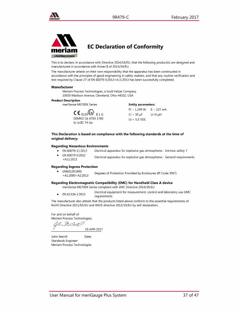
EC Declaration of Conformity – MS700X ............................... 37
EC Declaration of Conformity – MGP7000 ............................ 38
EC Declaration of Conformity – MS700 ................................. 39
Maintenance and cleaning .......................................................... 40
Protect your sensors from dust ............................................... 40
Inspect the vent on the sensors ............................................... 40
Hazardous Material and Recycling Compliance ................... 41
Part numbers ................................................................................ 42
Help ............................................................................................... 43
Register your product ............................................................... 43

9R479-C February 2017
User Manual for meriGauge Plus System 4 of 47
Find downloads and documents ............................................. 43
For repair or calibration .......................................................... 44
Troubleshooting checklist ........................................................ 46
Meriam Contact Information .................................................. 47

9R479-C February 2017
User Manual for meriGauge Plus System 5 of 47
General information
Notification Statements
Disclaimer Every precaution has been taken in the preparation of this manual. Nevertheless, Meriam assumes no responsibility for errors or omissions or any damages resulting from the use of the information contained in this publication, including, without limitation, incidental, special, direct or consequential damages. MERIAM MAKES NO REPRESENTATIONS OR WARRANTIES WITH RESPECT TO THE ACCURACY OR COMPLETENESS OF THE CONTENTS HEREOF AND SPECIFICALLY DISCLAIMS ANY IMPLIED WARRANTIES OF MERCHANTABILITY OR FITNESS FOR ANY PARTICULAR PURPOSE. Meriam reserves the right to revise this publication and to make changes from time to time in the content hereof without obligation to notify any person of such revision or changes.
In no event shall Meriam be liable for any indirect, special, incidental, consequential, or punitive damages or for any lost profits arising out of or relating to any services provided by Meriam or its affiliates.
It is not possible for Meriam to identify all foreseeable uses or misuses, therefore all persons involved in commissioning, using, or maintaining this product must satisfy their self that each intended application is acceptable.
Copyright This publication is proprietary to Meriam and no ownership rights are transferred. Neither this manual, nor any of the material contained herein, may be reproduced without the prior written consent of Meriam.
Trademark information meriGauge® Plus, meriSense™, and meriSuite™ are trademarks of Meriam.
All other trademarks are the property of their respective owners.

9R479-C February 2017
User Manual for meriGauge Plus System 6 of 47
Glossary Words and phrases with their definitions.
Button or key
• A button always refers to an area on the screen that you can click to select functionality.
• A key always refers to hardware push buttons on the keyboard that you can press.
IS or Intrinsically Safe
The abbreviation “IS” is used in locations where there is limited space.
Meriam Calibration
Meriam calibration refers to any calibration completed at Meriam with Meriam traceability. Meriam calibration includes:
• Oven calibration.
• Multipoint Meriam adjustment.
User Calibration
User calibration refers to any calibration done outside of Meriam with non-Meriam traceability. User calibration includes:
• Multipoint user calibration or adjustment.

9R479-C February 2017
User Manual for meriGauge Plus System 7 of 47
General warnings and cautions
Preventing injury
Failure to follow all instructions could result in injury:
• Read the entire manual before using the meriGauge Plus System.
• Understand the contents before using the meriGauge Plus System.
• Follow all safety warnings and instructions provided with this product.
• Meet or exceed your employer’s safety practices.
Safety Symbols The following table defines the safety symbols, signal words, and corresponding safety messages used in the manual. These symbols:
• Identify potential hazards.
• Warn you about hazards that could result in personal injury or equipment damage.
Safety Symbols Explaining the symbols
This is the Read Instruction Manual symbol. This symbol indicates that you must read the instruction manual.
Indicates a potentially hazardous situation which, if not avoided, will result in death or serious injury.
Indicates a potentially hazardous situation which, if not avoided, could result in death or serious injury.
Indicates a potentially hazardous situation which, if not avoided, could result in minor or moderate injury.

9R479-C February 2017
User Manual for meriGauge Plus System 8 of 47
Safety Symbols Explaining the symbols
Indicates information essential for proper product installation, operation or maintenance.
Disclaimer: A special condition for the aluminum case
Rare incidents: The case is made of aluminum. If you mount it in a location where a category 1 G apparatus is required, you must install it in such a way, that ignition sources due to impact and friction sparks are excluded.
Choose the proper gauge and sensor for the right location
• Only use Intrinsically Safe gauges and sensors in hazardous locations.
• Never use General Purpose gauges or sensors in hazardous locations.

9R479-C February 2017
User Manual for meriGauge Plus System 9 of 47
Sample labels for General Purpose gauges
General Purpose—The meriGauge Plus label See the figure of a sample label below.
General Purpose—The meriSense Absolute marking See the figure of a sample General Purpose label below.
General Purpose—The meriSense Compound marking See the sample General Purpose figure label below.
Mod
el N
umbe
r Se
rial N
umbe
r M
odel
Num
ber
Seria
l Num
ber
9R479-C February 2017
User Manual for meriGauge Plus System 10 of 47
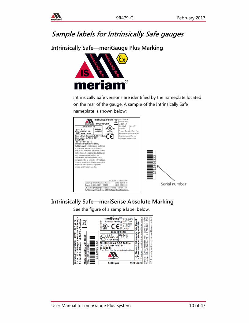
Sample labels for Intrinsically Safe gauges
Intrinsically Safe—meriGauge Plus Marking
Intrinsically Safe versions are identified by the nameplate located on the rear of the gauge. A sample of the Intrinsically Safe nameplate is shown below:
Intrinsically Safe—meriSense Absolute Marking See the figure of a sample label below.

9R479-C February 2017
User Manual for meriGauge Plus System 11 of 47
Intrinsically Safe—meriSense Compound Marking See the figure of a sample label below.
9R479-C February 2017
User Manual for meriGauge Plus System 12 of 47
Intrinsically Safe gauges
MGP7000X meriGauge Plus gauges
Directives for the proper use of equipment are located on 9R525-Intrinsically Safe Control Drawing that accompanies each MGP7000X shipped.
• Component substitution may impair Intrinsic Safety.
• Repairs must be made at Meriam to retain the Intrinsic Safety Certification.
• Service gauges only in a safe location.
• Replace batteries only in a safe location.
Intrinsically Safe sensors
MS700X meriSense sensors
Directives for the proper use of equipment are located on 9R526-Intrinsically Safe Control Drawing that accompanies each MS700X shipped.
• Component substitution may impair Intrinsic Safety.
• Repairs must be made at Meriam to retain the Intrinsic Safety Certification.
• Service sensors only in a safe location.

9R479-C February 2017
User Manual for meriGauge Plus System 13 of 47
Sensors
Make a pressure connection
Make a good NPT connection Each meriSense detachable sensor has a 316 stainless steel 1/4 in. male NPT connection for direct mounting.
• The threads should be coated with a pipe sealant compound before installation.
• Tighten to finger tight plus 1.5 turns to 3 turns using a 23 mm (7/8 in.) wrench.
Remember: The gauge will face the same direction as the Meriam logo on the sensor. See the Meriam logo in the red circle in the figure below.
Use only a wrench on the hex fitting
Never rotate a meriSense sensor by turning the meriGauge Plus gauge.

9R479-C February 2017
User Manual for meriGauge Plus System 14 of 47
meriSense information
Intrinsically Safe pressure ranges and range limits
MS700X meriSense
Contact [email protected] to purchase these parts and for more information about the following part numbers:
+ 1 216 281 1100 or (800) 817-7849.
MS700X meriSense sensors
Part number Ranges Type
ZMS700X-AI0005 0 psi to 5 psi Absolute
ZMS700X-CI0005 –15 psi to 5 psi Compound
ZMS700X-AI0015 0 psi to 15 psi Absolute
ZMS700X-CI0015 –15 psi to 15 psi Compound
ZMS700X-AI0030 0 psi to 30 psi Absolute
ZMS700X-CI0030 –15 psi to 30 psi Compound
ZMS700X-AI0050 0 psi to 50 psi Absolute
ZMS700X-CI0050 –15 psi to 50 psi Compound
ZMS700X-AI0100 0 psi to 100 psi Absolute
ZMS700X-CI0100 –15 psi to 100 psi Compound
ZMS700X-AI0300 0 psi to 300 psi Absolute
ZMS700X-CI0300 –15 psi to 300 psi Compound
ZMS700X-AI0500 0 psi to 500 psi Absolute
ZMS700X-CI0500 –15 psi to 500 psi Compound
ZMS700X-AI1000 0 psi to 1 000 psi Absolute
ZMS700X-CI1000 –15 psi to 1 000 psi Compound
ZMS700X-AI3000 0 psi to 3 000 psi Absolute
ZMS700X-CI3000 –15 psi to 3 000 psi Compound
• Includes all combined effects of linearity, repeatability, hysteresis, stability, and temperature over the specified calibrated temperature range for one year.
• Not recommended for continuous use below 0.02 psi absolute.

9R479-C February 2017
User Manual for meriGauge Plus System 15 of 47
General Purpose pressure ranges For General Purpose questions about sensor pressure ranges, contact [email protected] to purchase parts and for more information:
+ 1 216 281 1100 or (800) 817-7849.
Media compatibility 316 SS
Temperature limits
Operating temperature
–10 °C to 50 °C (14 °F to 122 °F)
• Up to 95 % RH non-condensing.
• No change in accuracy over operating temperature range.
• Gauge must be zeroed to achieve rated specification.
Process temperature
–10 °C to 50 °C (14 °F to 122 °F)
Warm-up time
Five (5) minutes.
Accuracy Statement
Absolute sensor
0 % to 110 % of Range: ± (0.02 % of Full Scale) + 0 % to 110 % of Range: (0.005 % of Reading)
Compound sensor
0 % to 110 % of Range: ± (0.02 % of Full Scale) + 0 % to 110 % of Range: (0.005 % of Reading) Vacuum*: ± (0.02 % of Full Scale) *Vacuum = –14.5 psi
9R479-C February 2017
User Manual for meriGauge Plus System 16 of 47
Pressure limits
Operating pressure limits
• Do not exceed the pressure limits listed in the sensor pressure ranges section for the MS700X meriSense.
• Failure to operate within the specified pressure limits could result in injury.
Overrange limit
Overrange pressure means the value is outside the calibrated upper or lower range.
• Up to 110 % of range, meriGauge Plus displays the accurate pressure.
• Above 110 %, it flashes red. This indicates that the applied pressure exceeds the calibrated range.
Note: If the calibrated pressure range is exceeded, the pressure displayed may not be accurate
• Above 120 %, it flashes red and displays dashes.
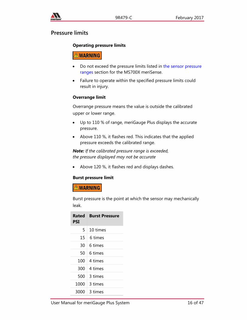
Burst pressure limit
Burst pressure is the point at which the sensor may mechanically leak.
Rated PSI
Burst Pressure
5 10 times
15 6 times
30 6 times
50 6 times
100 4 times
300 4 times
500 3 times
1000 3 times
3000 3 times

9R479-C February 2017
User Manual for meriGauge Plus System 17 of 47
Gauge
Batteries
Know your batteries A list of batteries for the meriGauge Plus that have been approved (Intrinsically Safe) for use in Hazardous Locations. No substitutions are allowed.
• Duracell MN1500
• Duracell PC1500
• Energizer EN91
• Panasonic LR6XWA
• Rayovac 815
• Varta 4906
Note: The meriGauge Plus is powered by four 1.5 volt AA size batteries.
• Never mix batteries—not by manufacturer or by size, by capacity, or by chemistry.
• Never mix old and new batteries.
• Remove all four batteries in the meriGauge Plus at the same time.
• Replace all four batteries with batteries from the same package or with the same expiration date.
Install the batteries Do not change batteries in hazardous locations.
1. Turn over the meriGauge Plus so the display faces down.
2. Remove the four screws on the battery cover with the Phillips head screwdriver by turning them counterclockwise.
3. Remove plastic battery cap.
4. Insert the four AA batteries.
Note: Pay attention to the positive (+) and negative (−) battery polarity markings at the bottom of the compartment.
5. Replace plastic battery cap.
9R479-C February 2017
User Manual for meriGauge Plus System 18 of 47
Note: Must be installed for use in hazardous location.
6. Replace the battery cover.
7. To secure the cover, torque the screws clockwise 0.56 N-m (5 in-lbs) maximum.
Watch for low battery indicators The battery indicator on the display shows the current charge.
Note: Be prepared to change batteries when you see the outline of the battery icon when the outline of the battery icon flashes.
Using the Backlight reduces your battery life Turn it off to optimize battery life.
Refer to the battery manufacturers’ instructions Visit the website of the battery manufacturer to learn more about the care, storage, shipping, use, disposal, and recycling of your batteries.
Consider inserting new batteries
Before you begin data logging or running a Rate of Change.
9R479-C February 2017
User Manual for meriGauge Plus System 19 of 47
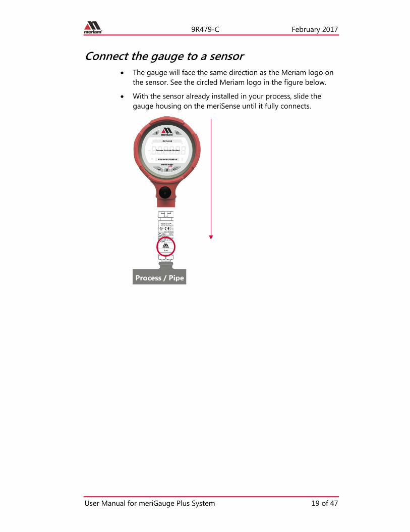
Connect the gauge to a sensor • The gauge will face the same direction as the Meriam logo on
the sensor. See the circled Meriam logo in the figure below.
• With the sensor already installed in your process, slide the gauge housing on the meriSense until it fully connects.
Process / Pipe

9R479-C February 2017
User Manual for meriGauge Plus System 20 of 47
The display
The keys
The bar graph The bar graph displays a live indication of the current pressure applied to the sensor as a % of Full Scale.
Note: When you press the Information key, the bar graph displays the remaining state of the charge for the batteries.

9R479-C February 2017
User Manual for meriGauge Plus System 21 of 47
Backlight in the LCD display
White backlight The white backlight has an automatic timeout. If you do not press any keys while the backlight is on, it automatically turns off after 1 minute.
Note: You can configure the backlight timeout with meriSuite CG.
Levels of backlight intensity Press the Backlight key to cycle through the choices:
• Low.
• Medium.
• High.
• Off.
Flashing red backlight The flashing red backlight indicates an error condition. Possible error conditions are:
• Pressure has exceeded the calibrated accuracy of the meriSense.
• Pressure has fallen below the stated accuracy of the meriSense.
Note: The red backlight overrides the white backlight.
Display modes
When meriGauge ships, it has nine (9) display modes
1. Normal
2. Minimum (MIN)
3. Maximum (MAX)
4. Accuracy (+/–)
5. Tare (T.OFF, T.ON)
6. Average (AVG)
7. Rate of change per minute (RATE)
8. Data Log (DATA LOG)
9. Time & Temperature

9R479-C February 2017
User Manual for meriGauge Plus System 22 of 47
What does the Zero (Ø) key do?
In normal measure mode If the sensor is within a tolerance band around zero, press and hold the Zero key to zero the pressure measurement and to reset the Min and Max measurements.
Note: The tolerance band is approximately ± 1 % of the Full Scale pressure value of the sensor.
In Min or Max mode Press and hold the Zero key to reset the Min and Max measurement. However, this does not zero the pressure measurement.
In Tare mode When the Tare is off (T.OFF), press and hold the Zero key to turn on Tare (T.ON) and to set the Tare value at the current pressure measurement.
Likewise, when the Tare is on (T.ON), press and hold the Zero key to turn off the Tare mode.
In Average mode Press and hold the Zero key to restart the rolling average.
In Data Log mode Press and hold the Zero key until you see—STARTING—appear on the LCD display to start recording a new data log.
Press and release the Zero key to log one data point during On Demand type.
Holding the Zero key The key must be held to perform the Zero or Tare mode. The displayed value(s) dashes out during the zero or tare process.

9R479-C February 2017
User Manual for meriGauge Plus System 23 of 47
Data Log Lite and Data Log Pro
View the “BATT %” before you begin Data Log Lite runs up to one hour.
Note: Do not start data logging if the outline of the battery icon is flashing.
Data Log Lite is limited to one data log Data Log Lite can record and hold only one data log at a time.
Note: When you press and hold the Zero key while DATA LOG appears in the LCD display, a new data log begins to record over the existing data log.
Data Log Pro provides a maximum of 128 logs Data Log Pro provides a maximum of 128 logs or a maximum of 100 000 data points.
Start the data logging process 1. Press the Display key until you see DATA LOG appear in the
LCD display.
2. Press and hold the Zero key until you see —STARTING—. The data log symbol starts to flash indicating it is recording data. Data Log Lite records data every 15 seconds for one hour.
3. —COMPLETE—appears after one hour.
Note: Auto Off is suspended during data logging. If you selected 5 Minutes for Auto Off, then meriGauge Plus remains on 5 minutes after data logging completes, and then turns off.
Stop the data logging process Here are some of the actions that can complete the data logging process before the one hour:
• Press and hold the Zero key until you see —STOPPING—.
• Press the Power key to turn off the meriGauge Plus.
• Remove the meriGauge Plus from a sensor.
• Connect the meriGauge Plus to the meriSuite CG app.
• The duration was reached that you selected in the Setup tab.

9R479-C February 2017
User Manual for meriGauge Plus System 24 of 47
Information key Where is the Information key on the meriGauge Plus?
The Information key is the red triangle in the Meriam logo.
What does the Information key normally display on the meriGauge Plus?
• BATT % displays the percentage on the bar graph and in digits.
• CAL DATE displays the date that Meriam calibrated the meriSense sensor.
• USL displays the Upper Specification Limit on the sensor.
• LSL displays the Lower Specification Limit on the sensor.
• LT MAX % displays the Life-Time Maximum that has been reached on the sensor.
• The characters SENSOR F/W display first and then they scroll across the screen from right to left to display VER. with the version number of the firmware.
• The characters SENSOR S/N display first and then they scroll across the screen from right to left to display S/N with the serial number of the sensor.
• The characters GAUGE F/W VER. display first and then they scroll across the screen from right to left to display VER. with the version number of the firmware.
• The characters GAUGE S/N display first and then they scroll across the screen from right to left to display S/N with the serial number of the gauge.
What does the Information key display while DATA LOG appears on the bottom row on the screen?
It displays the version of Data Log that you have: LITE or PRO.
1. Turn on meriGauge Plus.
2. Press the Display key on the gauge until you see Data Log.
3. Press the Information key once to display the version of data logging on the gauge:
• VERS. PRO for Data Log Pro.
• VERS. LITE for Data Log Lite.

9R479-C February 2017
User Manual for meriGauge Plus System 25 of 47
What additional information does the Information key display in Data Log Pro?
Press the Information key six more times to see these six notices in the following order on the gauge:
AVAIL PTS.
• The available points tell you how many points are available in the gauge memory.
• The maximum number of points is 100 000.
AVAIL LOG
• The available log tells you how many data logs are available in the gauge memory.
• The maximum number of data logs is 128.
TYP.
Type tells you which data logging type was selected in Setup tab in meriSuite CG for the gauge. There are four types:
• TYP. MEAS refers to Individual Samples.
• TYP. AVG refers to Average only.
• TYP. AVG+PK refers to Average with peaks.
• TYP. DEMAND refers to On Demand.
Note: See the Parameter Choices section in the meriSuite CG User Manual 9R609 for a description of the data log types.
INTERVAL.
• Interval tells you the hours, minutes, or seconds that was selected in Setup tab in meriSuite CG for the data log.
• Interval displays dashes “------“ when On Demand is the data log type. On Demand has no intervals.
PTS. CFG.
• Points Configured tells you the number of points that was selected in Setup tab in meriSuite CG for the data log.
• But, Points Configured displays dashes “------“ if the gauge was configured for a fixed amount of time.
• Additionally, Points Configured displays dashes “------“ if the Forever duration was selected.
9R479-C February 2017
User Manual for meriGauge Plus System 26 of 47
TIME CFG. (CFG. MIN, CFG. HR, CFG. DAYS, HR MIN, DAY HR)
• Time Configured tells you the duration that was selected in Setup tab in meriSuite CG for the data log.
• But, Time Configured displays dashes “------“ if the gauge was set to record a specific number of points.
• Additionally, Time Configured displays “------“ if the Forever duration was selected.
What does the Information key do while DATA LOG records data?
Toggle key
While recording data, the Information key becomes a toggle key. It toggles between the first notice: Log and point number and the second notice: days, hours, minutes, and seconds.
• Both notices display the remaining duration of points or time.
• When the duration is set for Minutes, Hours, Days, or Points, then the point number counts down to zero.
• When the point number reaches zero, the gauge displays --COMPLETED--.
Formats used in the LCD display
• Hours, minutes, and seconds in this format: HH.MM.SS
• Days, hours, minutes, seconds. DDD HH.MM.SS
• When the days, hours, minutes, and seconds reach zero, the gauge displays --COMPLETED--.
Note: When Days or Forever are selected for duration, then three additional (3) digits display for days up to a maximum of 366 days. The other six (6) digits display as hours, minutes, and seconds.
List of Measurement Units
Measurement units are stored on a sensor • Each meriSense sensor stores a complete list of measurement
units.
• The meriSuite CG app gives you the ability to configure specific measurement units to specific sensors.

9R479-C February 2017
User Manual for meriGauge Plus System 27 of 47
• The meriGauge Plus displays only the units selected in meriSuite CG for individual sensors.
• When the meriSense pressure sensors are shipped, the common 12 measurement units are available. These 12 units appear in bold type in the following Standard Units list.
Standard Units (non-custom)
1. PSI 2. INW20C 3. INW4C 4. INW60F 5. FTW20C 6. FTW4C 7. FTW60F 8. MMW20C 9. MMW4C 10. MMW60F 11. CMW20C
12. CMW4C 13. CMW60F 14. MW20C 15. MW4C 16. MW60F 17. INHG0C 18. MHG0C 19. CMHG0C 20. MMHG0C 21. TORR 22. KG/CM2
23. KG/M2 24. PA 25. HPA 26. KPA 27. MPA 28. BAR 29. MBAR 30. ATM 31. OZ/IN2 32. LB/FT2
Measurement units can be changed on a sensor • You must use the meriSuite CG app to select or deselect the
Standard Units on a particular sensor from the preceding list.
• By pressing the Units key on the gauge, you cycle through all the configured units within the currently attached meriSense that can be displayed on meriGauge plus.

9R479-C February 2017
User Manual for meriGauge Plus System 28 of 47
Auto Off (Automatic shutoff)
How long will the gauge remain on if I leave it unattended? • The default setting is Always On.
• You can configure the timeout for the Auto Off with meriSuite CG.
The timeout for Automatic Shutoff is suspended The timeout for the Auto Off is suspended:
1. During data logging sessions to prevent an accidental loss of information.
2. While the gauge is connected to a computer.
Auto Off is automatically re-instated after data logging is completed and after the gauge is disconnected from the computer.
Prepare the meriGauge Plus for storage
Remove the batteries to store the gauge 1. Remove the batteries from the meriGauge Plus to store it for
30 days or more.
2. Follow the battery manufacturer’s instructions for storing your batteries.
Store the meriGauge Plus The recommended storage temperature for the meriGauge Plus is between –20 ºC to 70 ºC (–4 ºF to 158 ºF).
Do not use the USB in hazardous locations
Connect a USB in safe locations only.

9R479-C February 2017
User Manual for meriGauge Plus System 29 of 47
Application
meriSuite CG and USB Drivers required
First—Install meriSuite CG 1. Read the meriSuite™ CG Installation Instructions 9R606 on the
Downloads page on www.meriam.com.
2. The instructions have a link that you can click to download the meriSuite CG setup file.
3. Follow the on-screen instructions.
Second—Install USB Drivers 1. Read the USB Drivers Installation Instructions 9R607 on the
Downloads page on www.meriam.com.
2. The instructions have links that you can click to download the required USB Driver.
3. Follow the on-screen instructions.
Third—Read the meriSuite CG User Manual 1. Read the meriSuite CG User Manual on the Product Manuals
page on www.meriam.com.
Note: You are now ready to use the meriSuite CG app to configure, to view data, and to create reports for the meriGauge Plus System.

9R479-C February 2017
User Manual for meriGauge Plus System 30 of 47
Specifications
Approvals
MGP7000X Intrinsically Safe Model
ATEX II 1 G; Ex ia IIC T4 Ga DEMKO 16 ATEX 1809X
cULus Listed Intrinsically Safe, Exia Class I, Div. 1 Groups A, B, C, D: T4 Class I, Zone 0, AEx ia IIC T4 –10º C < Ta < +50º C
Entity parameters: Po = 1.249W, Io = 227mA, Co = 35 μF, Lo=0 μH, Uo = 5.5VDC
CE Compliance
MS700X Intrinsically Safe model
ATEX II 1 G; Ex ia IIC T4 Ga DEMKO 16 ATEX 1785
IECEx Ex ia IIC T4 Ga –10º C < Ta < +50º C IECEx UL 16.0120
cULus Listed Intrinsically Safe, Exia Class I, Div. 1 Groups A, B, C, D: T4 Class I, Zone 0, AEx ia IIC T4 –10º C < Ta < +50º C
Entity parameters: Pi = 1.249W, Ii = 227mA, Ci = 30 μF, Li=0 μH, Ui = 5.5VDC
CE Compliance
MGP7000 and MS700 (General Purpose models)
CE Compliance
9R479-C February 2017
User Manual for meriGauge Plus System 31 of 47
Display Specifications
Display rate The meriGauge Plus displays five (5) updates per second.
LCD Display • The LCD displays six (6) digits.
• The numerical display height is 17.8 mm (0.7 in.)
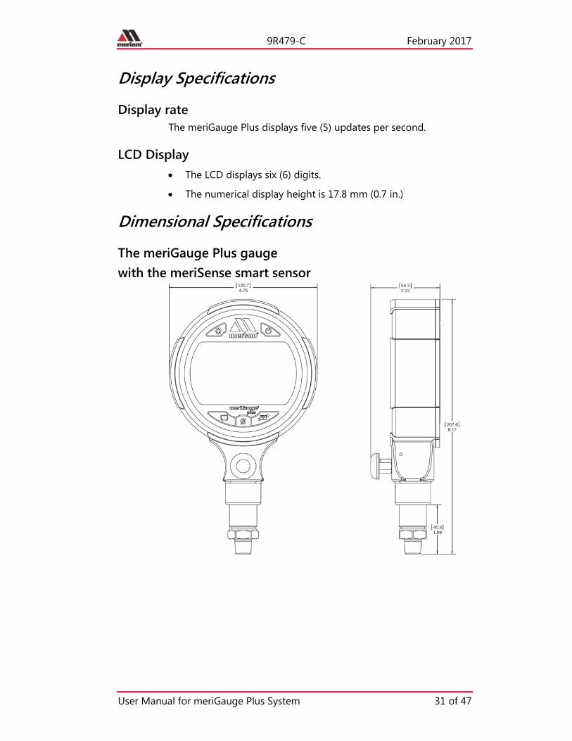
Dimensional Specifications
The meriGauge Plus gauge with the meriSense smart sensor

9R479-C February 2017
User Manual for meriGauge Plus System 32 of 47
Material specifications
meriGauge Plus aluminum housing The meriGauge Plus housing is made of these two types of aluminum:
• A356 Aluminum.
• 6061 Aluminum.
Disclaimer: Special condition for the aluminum case
Rare incidents: The case is made of aluminum. If you mount it in a location where a category 1 G apparatus is required, you must install it in such a way, that ignition sources due to impact and friction sparks are excluded.
meriSense The meriSense is made from 300 series stainless steel.
Ingress specifications • The meriGauge Plus is rated IP66.
• The meriSense is rated IP67.
Altitude specifications
Do not use the meriSense at an altitude above 2000 m (6561 ft).

9R479-C February 2017
User Manual for meriGauge Plus System 33 of 47
Safety
Hazardous locations use
Intrinsically Safe Model The meriGauge Plus MGP7000X and meriSense MS700X include certification for Intrinsically Safe operation.
Refer to the Intrinsic Safety Control Drawing for meriGauge 9R525 and for meriSense 9R526 in the Safety section in this manual for more information.
Hazardous locations and non-hazardous locations (safe locations)
The following table identifies model numbers and locations of acceptable use:
Model Number Location
Non-hazardous location (Safe location)
Hazardous location
MGP7000 General Purpose
Yes NO
MGP7000X Intrinsically Safe
Yes Yes
MS700 General Purpose
Yes NO
MS700X Intrinsically Safe
Yes Yes

9R479-C February 2017
User Manual for meriGauge Plus System 34 of 47
Intrinsic Safety Control Drawing for the meriGauge Plus gauge 9R525

9R479-C February 2017
User Manual for meriGauge Plus System 35 of 47
Intrinsic Safety Control Drawing for the meriSense sensors 9R526

9R479-C February 2017
User Manual for meriGauge Plus System 36 of 47
EC Declaration of Conformity – MGP7000X
9R479-C February 2017
User Manual for meriGauge Plus System 37 of 47
EC Declaration of Conformity – MS700X

9R479-C February 2017
User Manual for meriGauge Plus System 38 of 47
EC Declaration of Conformity – MGP7000

9R479-C February 2017
User Manual for meriGauge Plus System 39 of 47
EC Declaration of Conformity – MS700

9R479-C February 2017
User Manual for meriGauge Plus System 40 of 47
Maintenance and cleaning
Protect your sensors from dust
Keep the dust cap on sensors • Make sure you put the dust cap on the sensor after the
meriGauge Plus gauge has been detached from the sensor.
• The dust cap protects both the electrical contacts and the vent.
Inspect the vent on the sensors
Do not block vent 1. If the vent becomes blocked, it will cause inaccurate
measurements.
2. Meriam recommends that you visually inspect the vent area each time you use a meriSense sensor to make sure it is not blocked.
Cleaning sensors
• Use only water to clean sensors.
• Do not use solvents or cleaners.

9R479-C February 2017
User Manual for meriGauge Plus System 41 of 47
Hazardous Material and Recycling Compliance
Compliant with European Union Directives This product is compliant with these European Union Directives:
Directive Description
RoHS Directive 2011/65/EU
Reduction of Hazardous Substances
WEEE 2012/19/EU
Waste from Electrical and Electronic Equipment
Note: The following marking indicates that you must not discard this electrical / electronic product in domestic household waste.

9R479-C February 2017
User Manual for meriGauge Plus System 42 of 47
Part numbers Contact [email protected] for more information about these part numbers:
+ 1 216 281 1100 or (800) 817-7849
Part Numbers Descriptions
Z9P1521 USB A to right angle mini B –3 ft black cable
Z9P1055-2 Protective Boot
Z9A1354 Hard carrying case
Z9A878 “AA” Battery kit (4 pack)
Z9P1641 Activation Key for Data Log Pro

9R479-C February 2017
User Manual for meriGauge Plus System 43 of 47
Help
Register your product We want you to get the most out of your purchase, and that starts with a few, easy registration steps.
1. Go to www.meriam.com
2. On the Resources menu, click Register Your Product
Note: Or, click the link in step 2 to go directly to Register Your Product.
Find downloads and documents 1. Go to www.meriam.com/resources page.
2. Or, on the Resources menu, select one of these categories to find the files you need.
Product manuals | User Manuals and Quick Start Guides
Downloads | Applications (apps), firmware, updates, installation instructions
Certifications | Certifications and approvals
SDS (MSDS) | Safety Data Sheets
Control Drawings | Intrinsically Safe Drawings

9R479-C February 2017
User Manual for meriGauge Plus System 44 of 47
For repair or calibration
Contact Meriam for repair or calibration Meriam offers service and calibration on your products by certified technicians.
Reminder: You must have the model number and serial number ready when you contact us.
You have three options for requesting service:
Option 1: Complete and submit the For Repair & Calibration online form.
1. Go to www.meriam.com and click the Resources menu button.
2. Move the mouse pointer over For Repair & Calibration to see these two options:
a. Repair & Calibration.
b. RMA Request.
3. Complete either one online.
Reminders:
• You can see an estimated total price using the online form.
• You must include model number and serial number.
• Select Repair or Recalibration as the Service Type.
4. Click the Submit button to send the form to Meriam.
Option 2: Download a form to print and send to Meriam.
1. Click Service & Repair to see the link for Download form here in the first paragraph. You can download it and complete it later.
2. You can scan this form and send it by e-mail to [email protected] or fax it to us at:
+ 1 216 281 0228
USA and International Customers

9R479-C February 2017
User Manual for meriGauge Plus System 45 of 47
Option 3: Call Meriam to request repair or calibration.
+ 1 216 281 1100
USA (800) 817-7849
Before you ship anything to Meriam
1. You must receive a RMA number from Meriam first.
2. Clearly write on the package or place a shipping label on it with the RMA number (Return Material Authorization Number).
Note: we will return the gauge or sensor at your expense if we have not given you an RMA number.
3. An RMA number must appear on all packages that arrive at Meriam to properly track, process, and repair your gauge.
Do you have any questions? Call Meriam + 1 216 281 1100
USA (800) 817-7849
Ship the box to Meriam 10920 Madison Avenue Cleveland | Ohio | 44102 USA

9R479-C February 2017
User Manual for meriGauge Plus System 46 of 47
Troubleshooting checklist
The words “NO SENSOR” display on the gauge Follow these steps to troubleshoot the meriGauge Plus connection with meriSense sensor when the message NO SENSOR appears:
1. Turn off the meriGauge Plus gauge.
2. Remove the gauge from the sensor.
3. Re-attach the gauge to the sensor.
Remember: The gauge will face the same direction as the Meriam logo on the sensor. (You may hear it click when it locks in place.) See the Meriam logo in the red circle in the figure below.
Note: The locking pin prevents the gauge from accidentally disconnecting from the sensor.
4. Turn on the meriGauge Plus gauge.
Note: If the preceding steps do not work, contact Meriam Sales.

9R479-C February 2017
User Manual for meriGauge Plus System 47 of 47
Meriam Contact Information
Address Meriam Process Technologies
10920 Madison Avenue
Cleveland | Ohio | 44102 | USA
Telephone US customers (800) 817-7849
International customers + 1 216 281 1100
Fax US & International customers + 1 216 281 0228
E-mail addresses Return Material Authorization / Service & Repair Department
Sales
Website meriam.com
Find a local Meriam representative Use this map to help you find a Meriam representative.
http://www.meriam.com/representatives-map/