MERCHANT MARINE ACADEMY OF MACEDONIA · 3 Basic ship propulsion by J.P GHOSE and R.P GORKAN 2004,...
52
MERCHANT MARINE ACADEMY OF MACEDONIA SCHOOL OF ENGINEERS PROJECT IN ENGLISH: DESCRIPTION AND USE OF VARIOUS PROPULSION SYSTEMS IN VESSELS STUDENT: Lemonidis-Manthos Zisis AΓM: 4262 DELIVERY DATE: SUPERVISOR: Papadopoulou Anna
Transcript of MERCHANT MARINE ACADEMY OF MACEDONIA · 3 Basic ship propulsion by J.P GHOSE and R.P GORKAN 2004,...
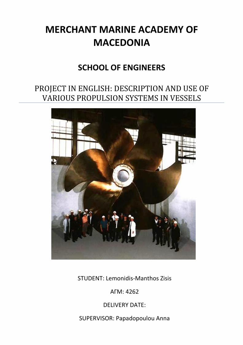
MERCHANT MARINE ACADEMY OF MACEDONIA
SCHOOL OF ENGINEERS
PROJECT IN ENGLISH: DESCRIPTION AND USE OF
VARIOUS PROPULSION SYSTEMS IN VESSELS
STUDENT: Lemonidis-Manthos Zisis
AΓM: 4262
DELIVERY DATE:
SUPERVISOR: Papadopoulou Anna

1
ABSTRACT
The purpose of this project is to give the reader the essential knowledge about propulsion
systems in vessels. In the next chapters there will be an analysis, of what a propulsion system is,
what the parts of a propulsion system consist of, the main power of propulsion systems (what kind
of engines and motors are used for ship propulsion) how a propulsion system works, and what
does every part of those systems do. Then in the following chapters there will be a display of the
types of propellers that are used in marine propulsion systems and the disadvantages of propeller
usage and the equipment that the systems have (the mechanical parts that stand between the
engine-motor and the propeller). Next there will be information on diesel-electric propulsion and
the steerable azimuth system. Finally, we will look into the experimental propulsion systems
(systems that are under construction) that are getting developed, and there will be a small layout
for the propulsion systems that various vessels are using (demonstrating what kind of engines the
vessels are using).
ΠΕΡΙΛΗΨΗ
Ο στόχος αυτής της εργασίας είναι να δώσει στον αναγνώστη την γνώση για τα
συστήματα προώσεως στα πλοία. Στα επόμενα κεφάλαια θα αναλυθεί, τι είναι το σύστημα
προώσεως, ποια είναι τα μέρη του, η κινητήριος δύναμη των συστημάτων αυτών (δηλαδή τις
μηχανές και τους κινητήρες που χρησιμοποιούνται στα συστήματα προώσεως των πλοίων) και
ετσι κατά συνέπεια θα εξηγηθεί πως δουλεύει το σύστημα και τι κάνει κάθε μέρος του
συστήματος. Στα επόμενα κεφάλαια θα παρουσιαστούν οι τύποι των ελίκων που έχουμε στην
θαλάσσια πρόωση, το πρόβλημα που δημιουργείται, κατά την λειτουργία της και ο εξοπλισμός
που έχουν τα συστήματα. Στην συνέχεια θα παρουσιαστούν τα κεφάλαια της ηλεκτρο-
διζελοκίνητης πρόωσης και της πρόωσης «χωρίς τιμόνι» . Και στο τέλος θα αναφερθούν τα
πειραματικά συστήματα προώσεως που αναπτύσονται (συστήματα που είναι υπό κατασκευή) και
θα υπάρξει μια μικρή παρουσίαση για τα συστήματα που χρησιμοποιούν διάφορα πλοία (τι
μηχανές χρησιμοποιούνται απο τα πλέον γνωστά πλοία).
2
INTRODUCTION
Marine propulsion is the mechanism or system used to move a ship or boat across water.
While paddles and sails are still used on some smaller boats, most modern ships are propelled by
mechanical systems consisting of a motor or engine turning a propeller, or less frequently, in jet
drives, an impeller. Marine engineering is the discipline concerned with the design of marine
propulsion systems.
The main engine of a ship is connected to its propeller with the help of a shaft. This whole system,
along with other vital machineries is known as the ship propulsion system. The type of propulsion
system used in a ship depends on several factors such as speed, power, ship type etc.
Steam engines were the first mechanical engines used in marine propulsion, but have mostly been
replaced by two-stroke or four-stroke diesel engines, outboard motors, and gas turbine engines on
faster ships. Nuclear reactors producing steam are used to propel warships and icebreakers, and
there have been attempts to utilize them to power commercial vessels. Electric motors have been
used on submarines and electric boats and have been proposed for energy-efficient propulsion.1
1 Basic ship propulsion by J.P GHOSE and R.P GORKAN 2004, published by Allied Publishers Pvt.
Limited (pages 1-3)
3
CHAPTER 1
PROPULSION SYSTEMS IN GENERAL
The choice of the appropriate propulsion system for a specific vessel is a very complicated
procedure that requires knowledge and experience.
To show how important is the right choice of the propulsion system, it has to be noted that the
cost of the facility may reach the 25% of the ship’s total cost. However the cost of the operation
will be more than 20 times the cost of the facility, because the cost of the operation in 2 years is
going to be equal with the cost of the facility.
It is obvious that the choice of a propulsion system with low operation cost is more important than
a choice of a system with low cost of construction. Of course, the cost of the operation is not the
only criterion for choosing the most appropriate system for the ship we are interested in.
The main requirements, that have to do with the propulsion system, are the following:
It must occupy the least possible space and have the least possible weight.
The cost for its function and maintenance should be the least possible.
It must be able to consume low quality fuel oil, without major consequences on the
reliability of the operation and the cost of maintenance.
The facility must be as simple as it can be, for increasing reliability and reducing of the
maintenance cost.
The facility should be operating with small number of trained personnel.
The facility must provide power to the propeller in the best way for the ship’s design, in the
most appropriate speed and torque.
The construction cost must be the lowest possible.
Nowadays, technology and knowledge of propulsion systems are at a satisfying level, so there are
plenty of choices. However it has to be noted, that the propulsion system for the ships are
selected based on a specific «unwritten» protocol that has to do with the type of the ship. In the

4
following chapters the main propulsion systems will be displayed and the most popular system in
marine propulsion.2
2 Internal combustion engines volume 2 2008, published by Institute Eugenidou (pages 99-103)

5
CHAPTER 2
THE MAIN PARTS OF THE PROPULSION SYSTEMS
Mechanical propulsion systems generally consist of a motor or engine turning a propeller,
or less frequently, an impeller or wave propulsion fins. Steam engines were first used for this
purpose, but have mostly been replaced by two-stroke or four-stroke diesel engines, outboard
motors, and gas turbine engines on faster ships. Nuclear reactors producing steam are used to
propel warships and icebreakers, and there have been attempts to utilize them to power
commercial vessels.
In addition to traditional fixed and controllable pitch propellers there are many specialized
variations, such as contra-rotating and nozzle-style propellers. Most vessels have a single
propeller, but some large vessels may have up to four propellers supplemented with transverse
thrusters for manoeuvring at ports. The propeller is connected to the main engine via a propeller
shaft and, in case of medium- and high-speed engines, a reduction gearbox. Some modern vessels
have a diesel-electric power train in which the propeller is turned by an electric motor powered by
the ship's generators.3
Image 2. 1 A small propulsion system (BoatDesign.net)
3 Basic ship propulsion by J.P GHOSE and R.P GORKAN 2004, published by Allied Publishers Pvt.
limited
6
CHAPTER 3
HOW DOES A PROPULSION SYSTEM WORK
The primary function of any marine engineering plant is to convert the chemical energy of
a fuel into useful work and to use that work for the Propulsion of the ship. A propulsion unit
consists of the machinery, equipment, and controls that are mechanically, electrically, or
hydraulically connected to a propulsion shaft. There are three main types of propulsion units used
in the Navy, and the power is transmitted from the propulsion unit to the ship’s propeller through
the use of gears, shafts, and clutches.
A ship moves through the water by propelling to the direction that specific devices allow, such as
paddle wheels or propellers. These devices impart velocity to a column of water and move it in the
direction opposite to move the ship. A force, called reactive force because it reacts to the force of
the column of water, is developed against the velocity imparting device. This force, also called
thrust, is transmitted to the ship and causes the ship to move through the water. The screw-type
propeller is the propulsion device used in almost all naval ships. The thrust developed on the
propeller is transmitted to the ship’s structure by the main shaft through the thrust bearing.
The main shaft extends from the main reduction gear shaft of the reduction gear to the propeller.
It is supported and held in alignment by the spring bearings, the stern tube bearings, and the
thrust bearing. The thrust, acting on the propulsion shaft as a result of the pushing effect of the
propeller, is transmitted to the ship’s structure by the main thrust bearing. In most ships, the main
thrust bearing is located at the forward end of the main shaft within the main reduction gear
casing. In some very large ships, however, the main shaft thrust bearing is located farther aft in a
machinery space or a shaft alley.
The main reduction gear connects the prime mover (engine) to the shaft. The function of the main
reduction gear is to reduce the high rotational speeds of the engine and allow the propeller to
operate at lower rotation speeds. In this way, both the engine and the propeller shaft rotate at
their most efficient speeds.4
4 Basic ship propulsion by J.P GHOSE and R.P GORKAN 2004, published by Allied Publishers Pvt.
Limited (pages 1-3)

7
Image 3. 1 The structure of a propulsion system (BoatDesign.net)
8
CHAPTER 4
THE MAIN POWER IN PROPULSION SYSTEMS
4.1 RECIPROCATING STEAM ENGINES
The first engines, which worked in ships, were steam engines. A steam engine is a heat
engine that performs mechanical work using steam as its working fluid. Steam engines are
typically external combustion engines.
A wide variety of reciprocating marine steam engines developed over the course of the 19th
century.
The two main methods of classifying such engines are by connection mechanism and cylinder
technology.
Most early marine engines had the same cylinder technology (simple expansion,) but a number of
different methods of supplying power to the crankshaft (i.e. connection mechanism) were in use.
Thus, early marine engines are classified mostly according to their connection mechanism. Some
common connection mechanisms were side-lever, steeple, walking beam and direct-acting.
However, steam engines can also be classified according to their cylinder technology (simple
expansion, compound, annular etc.). One can therefore sometimes find examples of engines
which were classified under both methods, such as the compound walking beam (compound being
the cylinder technology and walking beam being the connection method). Over time, as most
engines became direct-acting but cylinder technologies were growing more complex, engines
began to be classified solely according to their cylinder technology instead.

9
Image 4. 1 A reciprocating steam engine (Martin's Maritime Engineering Page)
4.2 RECIPROCATING DIESEL ENGINES
Most modern ships utilise a reciprocating diesel engine as their prime mover, due to their
operating simplicity, robustness and fuel economy compared to most other prime mover
mechanisms. The rotating crankshaft can be directly coupled to the propeller with slow speed
engines, via a reduction gearbox for medium and high speed engines, or via an alternator and
electric motor in diesel-electric vessels.
The reciprocating marine diesel engine first came into use in 1903 when the diesel electric river
tanker Vandal was put in service by Branobel. Diesel engines soon offered greater efficiency than
the steam turbine, but for many years had an inferior power-to-space ratio. The advent of turbo
charging however hastened their adoption, by permitting greater power densities.
Diesel engines today are broadly classified according to:
4.2.1 Their operating cycle: two-stroke engine or four-stroke engine:
Two-stroke engine: A two-stroke engine is an internal combustion engine that completes
the process cycle in one revolution of the crankshaft (an up stroke and a down stroke of
the piston, compared to twice that number for a four-stroke engine). This is accomplished
by using the end of the combustion stroke and the beginning of the compression stroke to
perform simultaneously the intake and exhaust (or scavenging) functions. In this way, two-

10
stroke engines often provide high specific power, at least in a narrow range of rotational
speeds. The functions of some or all of the valves required by a four-stroke engine are
usually served in a two-stroke engine by ports that are opened and closed by the motion of
the piston(s), greatly reducing the number of moving parts. Gasoline (spark ignition)
versions are particularly useful in lightweight (portable) applications, such as chainsaws,
and the concept is also used in diesel compression ignition engines in large and weight
insensitive applications, such as ships.
Four-stroke engine: A four-stroke engine, also known as four-cycle, is an internal
combustion engine in which the piston completes four separate strokes—intake,
compression, power, and exhaust—during two separate revolutions of the
engine's crankshaft, and one single thermodynamic cycle. The four cycles refer to intake,
compression, combustion (power), and exhaust cycles that occur during two crankshaft
rotations per power cycle of the four cycle engines. The cycle begins at Top Dead
Centre (TDC), when the piston is farthest away from the axis of the crankshaft. A cycle
refers to the full travel of the piston from Top Dead Centre (TDC) to Bottom Dead Centre
(BDC). (See Dead centre.)
INTAKE stroke: on the intake or induction stroke of the piston, the piston descends from the top of
the cylinder to the bottom of the cylinder, reducing the pressure inside the cylinder. A mixture of
fuel and air, or just air in a diesel engine, is forced by atmospheric (or greater) pressure into the
cylinder through the intake port. The intake valve(s) then close. The volume of air/fuel mixture
that is drawn into the cylinder, relative to the volume of the cylinder is called, the volumetric
efficiency of the engine.
COMPRESSION stroke: with both intake and exhaust valves closed, the piston returns to the top of
the cylinder compressing the air, or fuel-air mixture into the combustion chamber of the cylinder
head.
POWER stroke: this is the start of the second revolution of the engine. While the piston is close to
Top Dead Centre, the compressed air–fuel mixture in a gasoline engine is ignited, usually by
a spark plug, or fuel is injected into the diesel engine, which ignites due to the heat generated in
the air during the compression stroke. The resulting massive pressure from the combustion of the
compressed fuel-air mixture forces the piston back down toward bottom dead centre.

11
EXHAUST stroke: during the exhaust stroke, the piston once again returns to top dead centre while
the exhaust valve is open. This action evacuates the burnt products of combustion from the
cylinder by expelling the spent fuel-air mixture out through the exhaust valve(s).
4.2.2 Their construction: crosshead, trunk, or opposed piston
4.2.3 Their speed:
Slow speed: any engine with a maximum operating speed up to 300 revolutions per
minute (rpm), although most large two-stroke slow speed diesel engines operate below
120 rpm. Some very long stroke engines have a maximum speed of around 80 rpm. The
largest, most powerful engines in the world are slow speed, two stroke and crosshead
diesels.
Medium speed: any engine with a maximum operating speed in the range 300-900 rpm.
Many modern four-stroke medium speed diesel engines have a maximum operating speed
of around 500 rpm.
High speed: any engine with a maximum operating speed above 900 rpm.
Most modern larger merchant ships use slow speed, two stroke, crosshead engines, or medium
speed, four stroke, trunk engines. Some smaller vessels may use high speed diesel engines.
The size of the different types of engines is an important factor in selecting what will be installed
in a new ship. Slow speed two-stroke engines are much taller, but the footprint required, is
smaller than that needed for equivalently rated four-stroke medium speed diesel engines. As
space above the waterline is at a premium in passenger ships and ferries (especially ones with a
car deck), these ships tend to use multiple medium speed engines resulting in a longer, lower
engine room than that needed for two-stroke diesel engines. Multiple engine installations also
give redundancy in the event of mechanical failure of one or more engines, and the potential for
greater efficiency over a wider range of operating conditions.
As modern ships' propellers are at their most efficient at the operating speed of most slow speed
diesel engines, ships with these engines do not generally need gearboxes. Usually such propulsion
systems consist of either one or two propeller shafts with its own each, direct drive engine.

12
Ships propelled by medium or high speed diesel engines may have one or two (sometimes more)
propellers, commonly with one or more engines driving each propeller shaft through a gearbox.
Where more than one engine is geared to a single shaft, each engine will most likely drive through
a clutch, allowing engines not being used to be disconnected from the gearbox while others keep
running. This arrangement lets maintenance be carried out while under way, even far from port.
Image 4. 2 A two stroke diesel engine (SeekPart.com)
Image 4. 3 A four stroke diesel engine (Global Marine Services Co.Ltd.net)
4.3 STEAM TURBINES
A steam turbine is a mechanical device that converts thermal energy in pressurized steam
into useful mechanical work. The original steam engine which largely powered the industrial
revolution in the UK was based on reciprocating pistons. This has now been almost totally
replaced by the steam turbine because the steam turbine has a higher thermodynamic efficiency
and a lower power-to-weight ratio and the steam turbine is ideal for the very large power
configurations used in power stations. The steam turbine derives much of its better
thermodynamic efficiency because of the use of multiple stages in the expansion of the steam.
Steam turbines are made in a variety of sizes ranging from small 0.75 kW units used as mechanical
drives for pumps, compressors and other shaft driven equipment, to 1,500,000kW turbines used
to generate electricity. Steam turbines are widely used for marine applications for vessel
propulsion systems. In recent times gas turbines, as developed for aerospace applications, are
being used more and more in the field of power generation once dominated by steam turbines.
13
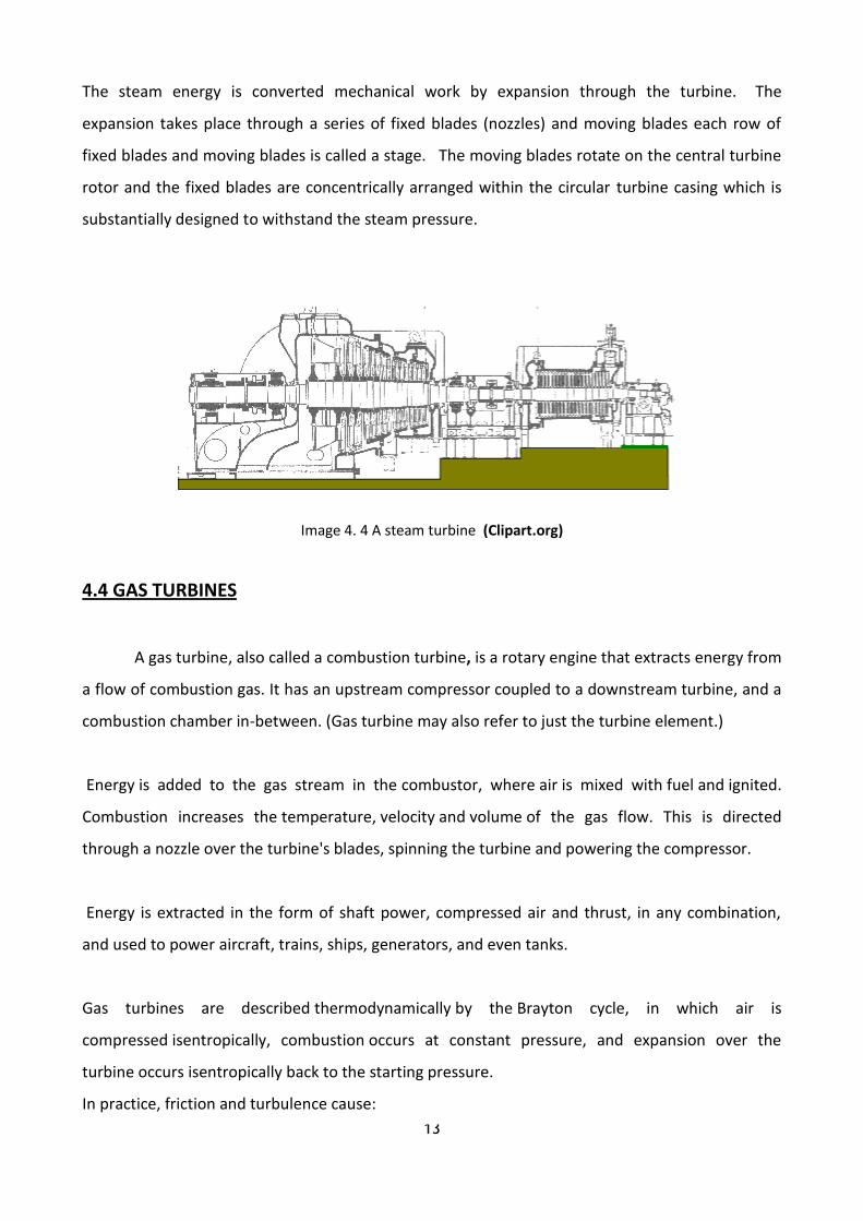
The steam energy is converted mechanical work by expansion through the turbine. The
expansion takes place through a series of fixed blades (nozzles) and moving blades each row of
fixed blades and moving blades is called a stage. The moving blades rotate on the central turbine
rotor and the fixed blades are concentrically arranged within the circular turbine casing which is
substantially designed to withstand the steam pressure.
Image 4. 4 A steam turbine (Clipart.org)
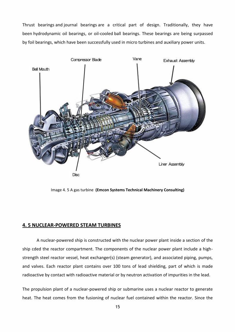
4.4 GAS TURBINES
A gas turbine, also called a combustion turbine, is a rotary engine that extracts energy from
a flow of combustion gas. It has an upstream compressor coupled to a downstream turbine, and a
combustion chamber in-between. (Gas turbine may also refer to just the turbine element.)
Energy is added to the gas stream in the combustor, where air is mixed with fuel and ignited.
Combustion increases the temperature, velocity and volume of the gas flow. This is directed
through a nozzle over the turbine's blades, spinning the turbine and powering the compressor.
Energy is extracted in the form of shaft power, compressed air and thrust, in any combination,
and used to power aircraft, trains, ships, generators, and even tanks.
Gas turbines are described thermodynamically by the Brayton cycle, in which air is
compressed isentropically, combustion occurs at constant pressure, and expansion over the
turbine occurs isentropically back to the starting pressure.
In practice, friction and turbulence cause:
14
Non-isentropic compression: for a given overall pressure ratio, the compressor delivery
temperature is higher than ideal.
Non-isentropic expansion: although the turbine temperature drop necessary to drive the
compressor is unaffected, the associated pressure ratio is greater, which decreases the
expansion available to provide useful work.
Pressure losses in the air intake, combustor and exhaust: reduces the expansion available
to provide useful work.
As with all cyclic heat engines, higher combustion temperature means greater efficiency. The
limiting factor is the ability of the steel, nickel, ceramic, or other materials that make up the
engine to withstand heat and pressure. Considerable engineering goes into keeping the turbine
parts cool. Most turbines also try to recover exhaust heat, which otherwise is wasted
energy. Remunerators are heat exchangers that pass exhaust heat to the compressed air, prior to
combustion. Combined cycle designs pass waste heat to steam turbine systems. And combined
heat and power (co-generation) use waste heat for hot water production.
Mechanically, gas turbines can be considerably less complex than internal combustion piston
engines. Simple turbines might have one moving part: the shaft/compressor/turbine/alternative-
rotor assembly (see image above), not counting the fuel system. However, the required precision
manufacturing for components and temperature resistant alloys necessary for high efficiency
often makes the construction of a simple turbine more complicated than piston engines.
More sophisticated turbines (such as those found in modern jet engines) may have multiple shafts
(spools), hundreds of turbine blades, movable stator blades, and a vast system of complex piping,
combustors and heat exchangers.
As a general rule, the smaller the engine the higher the rotation rate of the shaft(s) needs to be to
maintain top speed. Turbine blade top speed determines the maximum pressure that can be
gained; this produces the maximum power possible independent of the size of the engine. Jet
engines operate around 10,000 rpm and micro turbines around 100,000 rpm.
15
Thrust bearings and journal bearings are a critical part of design. Traditionally, they have
been hydrodynamic oil bearings, or oil-cooled ball bearings. These bearings are being surpassed
by foil bearings, which have been successfully used in micro turbines and auxiliary power units.
Image 4. 5 A gas turbine (Emcon Systems Technical Machinery Consulting)
4. 5 NUCLEAR-POWERED STEAM TURBINES
A nuclear-powered ship is constructed with the nuclear power plant inside a section of the
ship cded the reactor compartment. The components of the nuclear power plant include a high-
strength steel reactor vessel, heat exchanger(s) (steam generator), and associated piping, pumps,
and valves. Each reactor plant contains over 100 tons of lead shielding, part of which is made
radioactive by contact with radioactive material or by neutron activation of impurities in the lead.
The propulsion plant of a nuclear-powered ship or submarine uses a nuclear reactor to generate
heat. The heat comes from the fusioning of nuclear fuel contained within the reactor. Since the
16
fusioning process also produces radiation, shields are placed around the reactor so that the crew is
protected.
The nuclear propulsion plant uses a pressurized water reactor design which has two basic systems
- a primary system and a secondary system. The primary system circulates ordinary water and
consists of the reactor, piping loops, pumps and steam generators. The heat produced in the
reactor is transferred to the water under high pressure so it does not boil. This water is pumped
through the steam generators and back into the reactor for re-heating.
In the steam generators, the heat from the water in the primary system is transferred to the
secondary system to create steam. The secondary system is isolated from the primary system so
that the water in the two systems does not intermix.
In the secondary system, the steam flows from the steam generators to drive the turbine
generators, which supply the ship with electricity, and to the main propulsion turbines, which
drive the propeller. After passing through the turbines, the steam is condensed into water which is
fed back to the steam generators by the feed pumps. Thus, both the primary and secondary
systems are closed systems where water is recirculated and renewed.
Naval reactors undergo repeated power changes for ship manoeuvring, unlike civilian
counterparts which operate at steady state. Nuclear safety, radiation, shock, quieting, and
operating performance requirements in addition to operation in close proximity to the crew
dictate exceptionally high standards for component manufacturing and quality assurance. The
internals of a Naval reactor remain inaccessible for inspection or replacement throughout a long
core life -- unlike a typical commercial nuclear reactor, which is opened for refuelling roughly
every eighteen months.
Since there is no step in the generation of this power which requires the presence of air or oxygen,
this allows the ship to operate completely independent from the earth’s atmosphere for extended
periods of time.5
5 Diesel engine design by H. F. P. PURDAY published by Constable, 1948 5th edition (pages 201-
210, 226-233, 267-277, 280-285)

17
Image 4. 6 A nuclear powered steam turbine system (Federation of American Scientists)

18
CHAPTER 5
THE PROPELLERS
A propeller is a type of fan that transmits power by converting rotational motion
into thrust. A pressure difference is produced between the forward and rear surfaces of the airfoil-
shaped blade, and a fluid (such as air or water) is accelerated behind the blade. A propeller is
known as screw both in aviation and maritime.
A propeller is the most common propulsion on ships, imparting momentum to a fluid which
causes a force to act on the ship.
The ideal efficiency of any size propeller (free-tip) is that of an actuator disc in an ideal fluid. An
actual marine propeller is made up of sections of helicoidally surfaces which act together
'screwing' through the water (hence the common reference to marine propellers as "screws").
Three, four, or five blades are most common in marine propellers, although designs which are
intended to operate at reduced noise will have more blades. The blades are attached to
a boss (hub), which should be as small as the needs of strength allow - with fixed pitch propellers
the blades and boss are usually a single casting.
An alternative design is the controllable pitch propeller (CPP, or CRP for controllable-reversible
pitch), where the blades are rotated normal to the drive shaft by additional machinery -
usually hydraulics - at the hub and control linkages running down the shaft. This allows the drive
machinery to operate at a constant speed while the propeller loading is changed to match
operating conditions. It also eliminates the need for a reversing gear and allows for more rapid
change to thrust, as the revolutions are constant. This type of propeller is most common on ships
such as tugs where there can be enormous differences in propeller loading when towing
compared to running free, a change which could cause conventional propellers to lock up as
insufficient torque is generated.
The downsides of a CPP/CRP include: the large hub which decreases the torque required to cause
cavitations, the mechanical complexity which limits transmission power and the extra blade
shaping requirements forced upon the propeller designer.
19
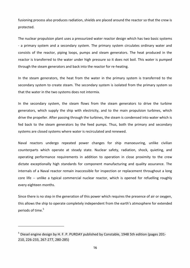
Image 5. 1 A typical heavy vessel’s propeller (Mitsubishi Heavy Industries, Ltd)
5. 1 TYPES OF PROPELLER
Propellers are be classified on the basis of several factors. The classification of different
types of propellers is shown below:
A) Classification by Number of Blades Attached:
Propeller blades may vary from 3 blade propellers to 4 blade propellers and sometimes even 5
blade propellers. However, the most commonly used are 3 blades and 4 blade propellers.
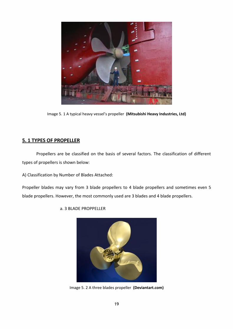
a. 3 BLADE PROPPELLER
Image 5. 2 A three blades propeller (Deviantart.com)

20
A 3 blade propeller has following characteristics:
- The manufacturing cost is lower than other types.
- Are normally made up of aluminium alloy.
- Gives a good high speed performance.
- The acceleration is better than other types.
- Low speed handling is not much efficient.
b. 4 BLADE PROPELLER
Image 5. 3 A four blade propeller (ShutterStock.com)
A 4 blade propeller has following characteristics:
- The manufacturing cost is higher than 3 blade propellers.
- 4 blade propellers are normally made up of stainless steel alloys.
- Have better strength and durability.
- Gives a good low speed handling and performance.
- Has a better holding power in rough seas.

21
- A 4 blade propeller provides a better fuel economy than all the other types.
c. 5 BLADE PROPELLER
Image 5. 4 A five blade propeller (NauticExpo)
A 5 blade propeller has following characteristics:
- Manufacturing cost is higher of all.
- Vibration is minimal from all the other types.
- 5 blade propellers have better holding power in rough seas.
B) Classification By pitches of the blade:
Pitch of a propeller can be defined as the displacement that a propeller ma es for every full
revolution of . he classification of the propellers on the basis of pitch is as follows.
a. Fixed Pitch Propeller:
22
The blades in fixed pitch propeller are permanently attached to the hub. The fixed pitch type
propellers are casted and the position of the blades and hence the position of the pitch is
permanently fixed and cannot be changed during the operation.
Fixed pitch propellers are robust and reliable as the system doesn’t incorporate any mechanical
and hydraulic connection as in Controlled Pitch Propeller (CPP). The manufacturing, installation
and operational costs are lower than controlled pitch propeller (CPP) type. The manoeuvrability of
fixed pitch propeller is also not as good as CPP.
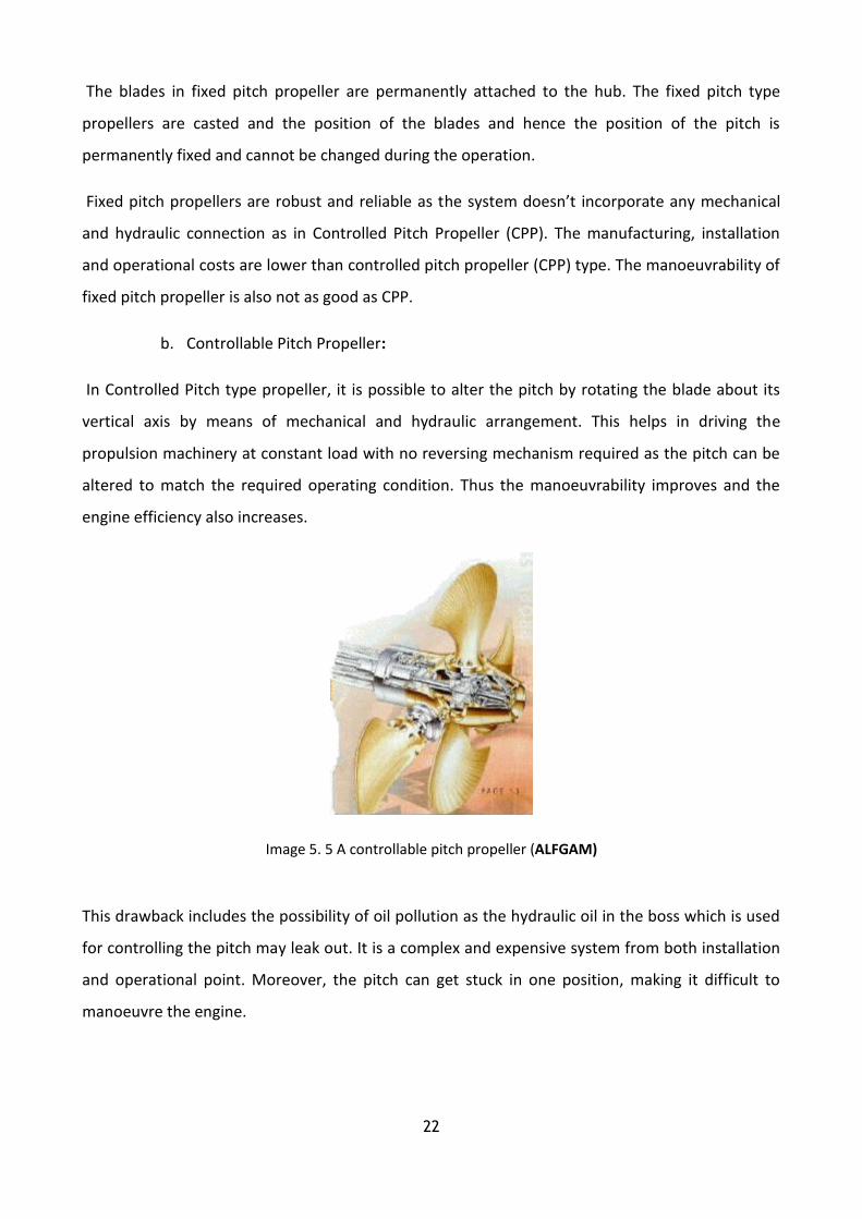
b. Controllable Pitch Propeller:
In Controlled Pitch type propeller, it is possible to alter the pitch by rotating the blade about its
vertical axis by means of mechanical and hydraulic arrangement. This helps in driving the
propulsion machinery at constant load with no reversing mechanism required as the pitch can be
altered to match the required operating condition. Thus the manoeuvrability improves and the
engine efficiency also increases.
Image 5. 5 A controllable pitch propeller (ALFGAM)
This drawback includes the possibility of oil pollution as the hydraulic oil in the boss which is used
for controlling the pitch may leak out. It is a complex and expensive system from both installation
and operational point. Moreover, the pitch can get stuck in one position, making it difficult to
manoeuvre the engine.
23
5.2 CAVITATION
However, using a propeller to give thrust power to a ship, leads to a big problem. The cavitation
problem.
Cavitation is the formation and then immediate implosion of cavities in liquid – i.e. small liquid-
free zones ("bubbles") – that are the consequence of forces acting upon the liquid. It usually
occurs when a liquid is subjected to rapid changes of pressure that cause the formation of cavities
where the pressure is relatively low.
Cavitation is a significant cause of wear in some engineering contexts. When entering high
pressure areas, cavitation bubbles that implode on a metal surface cause cyclic stress. These
results in surface fatigue of the metal causing a type of wear also called "cavitation". The most
common examples of this kind of wear are pump impellers and bends when a sudden change in
the direction of liquid occurs. Cavitation is usually divided into two classes of behaviour: inertial
(or transient) cavitation and non-inertial cavitation.
Inertial cavitation is the process where a void or bubble in a liquid rapidly collapses, producing
a shock wave. Inertial cavitation occurs in nature in the strikes of mantis shrimps and pistol
shrimps, as well as in the vascular tissues of plants. In man-made objects, it can occur in control
valves, pumps, propellers and impellers.
Non inertial cavitation is the process in which a bubble in a fluid is forced to oscillate in size or
shape due to some form of energy input, such as an acoustic field. Such cavitation is often
employed in ultrasonic cleaning baths and can also be observed in pumps, propellers, etc.
Since the shock waves formed by cavitation are strong enough to significantly damage moving
parts, cavitation is usually an undesirable phenomenon. It is specifically avoided in the design of
machines such as turbines or propellers, and eliminating cavitation is a major field in the study
of fluid dynamics.6
6 Marine Propellers and Propulsion by JOHN CARTLON 2007, bublished by Elsevier Ltd.
(pages 1-10, 11-13, 20-23, 205-207)

24
Image 5. 6 The cavitation phenomena (Answers.com)

25
CHAPTER 6
MAIN PRINCIPALS AND EQUIPMENT OF PROPULSION SYSTEM FACILITIES
The engine room in the merchant ships is placed in the aft part of the ship, so the available
space can be maximized for the transportation of the ships loads and the ships propeller length
minimization, so the engine room can be near to the accommodation.
The symmetric distribution of the ships weights and the symmetric placement of the ships tanks in
the engine room are necessary, so they can not affect the ships stability. For that reason the heavy
components are placed at the lower possible level.
The sea water pumps must placed under the water line of the vessel, so when she is without load,
the problem of cavitations can be avoided. The similar machinery must be placed in a relative
close distance between them, so their manipulation is easy and the length of their plumbing is
small. The plumbing must not pass through tanks, for their inspection and their maintenance can
be easy.
The air reservoirs of the starting air system are placed in relative slope, so their drain can take
place easy.
6.1 Joints
When reduction gears are used between the engine and the propeller shaft, usually some kind
of joint is used after the engine and before the reduction gear. This joint has those operations:
Operates as dumper, so it can normalize the steep changes of the engines torques, and the
reduction gear can be protected.
It can be used as fast clutch of connection-disconnection during the manoeuvring
procedure.
Operates as safety system for the maximum torque that is being transferred.
The different categories of the joints that are used are: a) electromagnetic b) hydraulic c) air and
d) mechanical. The last category can not be used as clutch instead of the others.

26
Image 6. 1 Mechanical Joint (Fire Controlman)
6.2 REDUCTION GEARS
The reduction gears are used for decreasing the rotation speed of the engines shaft into a
speed that is appropriate for the maximum performance of the ships propeller. They use couples
of «toothed» gears, with different number of tooth and different diameter for each gear. The
reduction of the revolutions is accompanied by the increase of torque, so the transferred power
can be stable.
The reduction gears that are used in middle-stroke engines have one step of reduction, and the
gogging are simple or double helical. For the achievement of the reduction the gear with the small
gogging and diameter is obviously placed at the side of the engine and the big gear at the side of
the engines shaft. The ratio of revolutions reduction must not be higher than 4:1 but usually is
between 2:1 or 2, 5:1.
Image 6. 2double helical Reduction gears (Fire Controlman)

27
6.3 THRUST BLOCK
The thrust block transfers the movement from the propeller to the hull of the ship. It must
therefore be solidly constructed and mounted onto a rigid seating or framework of perform its
task. It may be an independent unit or an integral part of the main propulsion system. Both ahead
and astern thrusts must be catered for and the construction must be strong enough to withstand
normal and shock loads.
The casing of the independent thrust block is in two halves which is joint by fitted bolts. The thrust
loading is carried by bearing pads which are arranged to pivot or tilt. The pads are mounted in
holders or carriers and faced with white metal. In the arrangement shown the pads extend three-
quarter of the distance around the collar and transmit all thrust to the lower of the casing. Other
designs employ a complete ring of pads. An oil scraper deflects the oil lifted by the trust collar and
directs it onto the pad stops. From here it cascades over the thrust pads and bearings. The shaft is
manufactured with integral flanges for bolting to the engine or gearbox shaft and the intermediate
shafting, and the thrust collar for absorbing the thrust.
Image 6. 3 Thrust block (Mitchell type) (Wikipedia)
6.4 SHAFT BEARING
Shaft bearing are of two types, the aftermost tunnel bearing and all others. The aftermost
tunnel bearing has a top and a bottom bearing shell because it must counteract the propeller mass
and take a vertical upward thrust at the forward end of the tail shaft. The other shaft bearings only
support the shaft weight and thus have only lower bearing shell. The usual journal bush is here
replaced by pivoting pads. The tilting pad is better able to carry high overload, and retain a thick
oil lubricating film.
28
Lubrication is from a bath in the lower half of the casing and an oil thrower ring dips into the oil
and carries it round the shaft as it rotates. Cooling of the bearing is by water circulating through a
tube in the bottom of the casing.
Image 6. 4 Intermediate shaft bearing (Hi-Sea Marine)
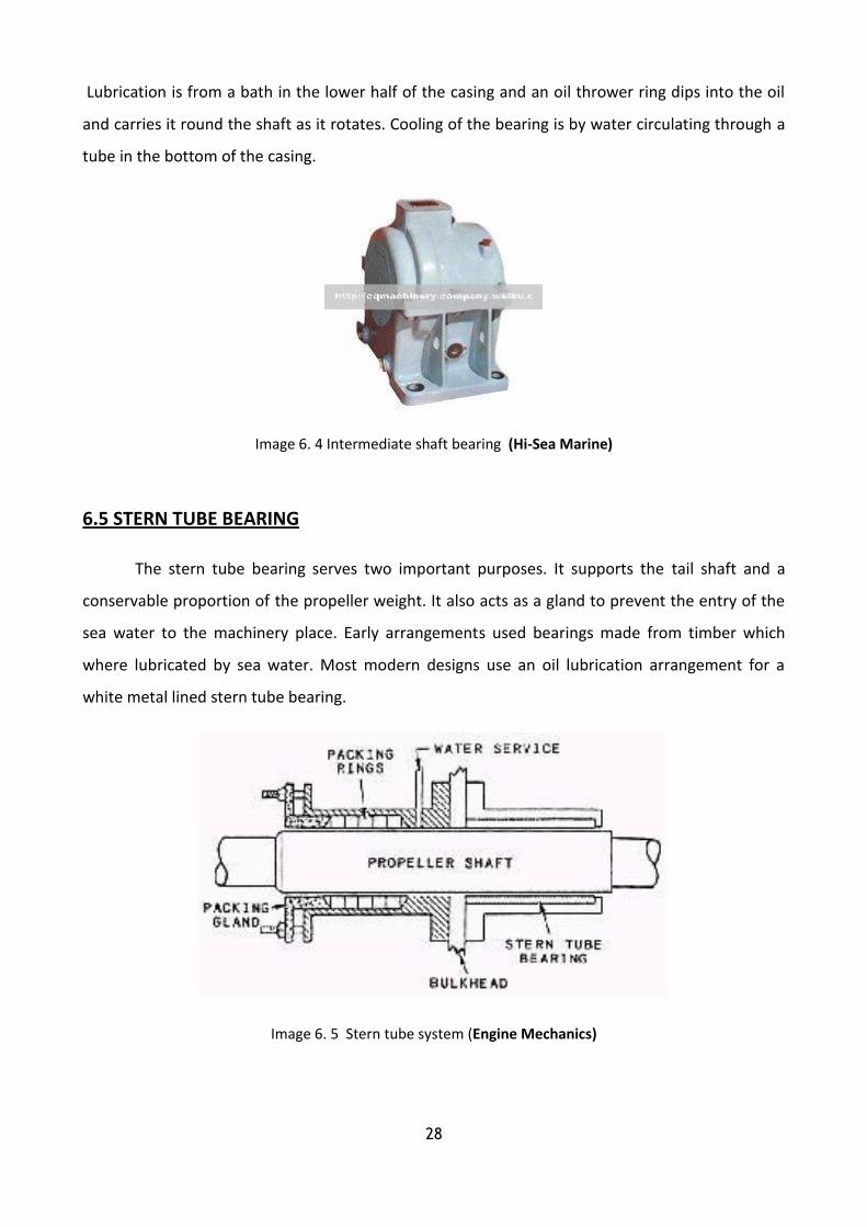
6.5 STERN TUBE BEARING
The stern tube bearing serves two important purposes. It supports the tail shaft and a
conservable proportion of the propeller weight. It also acts as a gland to prevent the entry of the
sea water to the machinery place. Early arrangements used bearings made from timber which
where lubricated by sea water. Most modern designs use an oil lubrication arrangement for a
white metal lined stern tube bearing.
Image 6. 5 Stern tube system (Engine Mechanics)

29
6.6 STERN TUBE SEALS
Special seals are fitted at the outboard ends of the tail shaft. They are arranged to prevent
the entry of the sea water and also the loss of the lubricating oil from the stern bearing.
Older designs, usually associated with sea water lubricated stern bearings, made use of a
conventional stuffing box and gland at the after bulk head oil. Lubricated stern bearings use either
lip or radial face seals or a combination of the two.
Lip seals are shaped rings of material with a projecting lip or edge which is held in contact with a
shaft to prevent oil leakage or water entry. A number of lip seals are usually fitted depending upon
the particular application face seals use a pair of mating radial faces to seal against leakage. One
face is stationary and the other rotates. The rotating face of the after seal is usually secured to the
propeller boss. The stationary face of the forward on in board seal is the after bulkhead as spring
arrangement forces the stationary and rotating face together.7
Image 6. 6 The way that stern tube is sealed (Marine Insight)
7 Marine English notes (semester E’)

30
CHAPTER 7
DIESEL-ELECTRIC PROPULSION
Diesel-electric transmission or diesel-electric power is used by a number of vehicle and ship
types for providing locomotion.
A diesel-electric transmission system includes a diesel engine connected to an electrical
generator, creating electricity that powers electric traction. No clutch is required.
Before diesel engines came into widespread use, a similar system, using petrol (gasoline)
engine and called petrol-electric or gas-electric, was sometimes used.
This kind of power transmission is used on railways by diesel electric locomotives and diesel
electric multiple units as only electric motors are able to supply full torque at 0 RPM. Diesel-
electric systems are also used in submarines and surface ships and some land vehicles.
In some high-efficiency applications, electrical energy may be stored in rechargeable batteries, in
which case these vehicles can be considered as a class of hybrid electric vehicle.
The first diesel motor ship was also the first diesel-electric ship, the Russian
tanker Vandal from Branobel, which was launched in 1903. Steam turbine-electric propulsion has
been in use since the 1920s (Tennessee class battleships), using diesel-electric power plants in
surface ships has increased lately. The Finnish coastal defence ship Ilmarinen, laid down in 1929,
was among the first surface ships to use diesel-electric transmission. Later, the technology was
used in diesel powered icebreakers.
Some modern ships, including cruise ships and icebreakers, use electric motors called azimuth
thrusters to allow 360° rotation, making the ships far more manoeuvrable.
Gas turbines are also used for electrical power generation and some ships use a combination:
the Queen Mary 2 has a set of diesel engines in the bottom of the ship plus two gas turbines
mounted near the main funnel; all are used for generating electrical power, including that used to

31
drive the propellers.8 Electric propulsion solutions with two or more shafts usually incorporate
electric motors which drive a propeller.
If an electric motor and a propeller are closely combined in one unit, this is called POD which can
be mounted externally to the main hull. The electric motors are supplied by electricity generators
which may consist entirely of gas turbines alternators, or be or a combination of diesel alternators
and gas turbines alternators. The diagram below shows an example of a "full electric" example of
architecture. The "prime movers" are two Rolls Royce WR-21 gas turbine alternator sets rated at
21MW, and four diesels alternators of 5-7MW, divided in to two units each powering a 28MW
electric motor which drives a propeller shaft.
Image 7. 1 A diesel electric propulsion system (Navy Matters)
8 Internal combustion engines volume 2 2008, published by Institute Eugenidou (pages
105-108)
32
CHAPTER 8
NON-CONVENTIONAL PROPULSION SYSTEMS
8.1 STEERABLE AZIMUTH DRIVE SYSTEM
An azimuth thruster is a configuration of ship propellers placed in pods that can be rotated
in any horizontal direction, making a rudder unnecessary. These give ships better maneuverability
than a fixed propeller and rudder system
There are two major variants, based on the location of the motor:
-Mechanical transmission, where a motor inside the ship is connected to the pod by gearing. The
motor may be diesel or diesel-electric. Depending on the shaft arrangement the mechanical
azimuth thruster are divided into L-drive and Z-drive. An L-drive thruster has a vertical input shaft
and horizontal output shaft with one right-angle gear. A Z-drive thruster has a horizontal input
shaft, vertical shaft in the rotating column and a horizontal output shaft with two right-angle
gears.
-Electrical transmission, where an electric motor is in the pod itself, connected directly to the
propeller without gears. The electricity is produced by an onboard engine, usually diesel or gas
turbine. Invented in 1955 and it was the first product using this technology.
Mechanical azimuth thrusters can be fixed installed, retractable and underwater-mountable. They
may have fixed pitch propellers (FPP) or controllable pitch propellers (CPP). Fixed installed
thrusters are used for tugs, ferries and supply-boats. Retractable thrusters are used as auxiliary
propulsion for dynamically positioned (DP) vessels and take-home propulsion for military vessels.
Underwater-mountable thrusters are used as dynamic positioning propulsion for very large vessels
such as semi-submersible drilling rigs.
Primary advantages are electrical efficiency, better use of ship space, and lower maintenance
costs. Ships with azimuth thrusters do not need tugs to dock, though they still require tugs to
maneuver in difficult places.

33
Image 8. 1 Steerable azimuth system propellers (Nautilia)
8.2 WATER JET PROPULSION
The water jet propulsion is based on the principal of action-reaction. Axial flow
hydrodynamic pump sucks water from the hull part and it launches it, through adjustable nozzle,
with high speed backwards. Due to the change of water’s momentum the vessel moves forward.
With the assistance of fins the water jet can move right and left and moves also the vessel right or
left. And with the descent of a special deflector the vessel moves backwards. The easy movement
and the deflection of the water jet allow the easy manoeuvring procedure and at the same time
create high speeds. 9
Image 8. 2 A water jet motor (TradeKorea.com)
9 Internal combustion engines volume 2 2008, published by Institute Eugenidou (pages
119-120)
34
CHAPTER 9
EXPERIMENTAL PROPULSION SYSTEMS
9.1 WIND PROPULSION
Wind propulsion emerged as an alternative to those systems which emit huge quantities of
CO2 gases in the marine atmosphere. However, the usage of wind turbine marine propulsion
has not started extensively in large commercial ships because of a requirement of constant
windiness. Two wind propulsion systems for ships that have become lately are- kite
propulsion and sail propulsion for merchant ships.
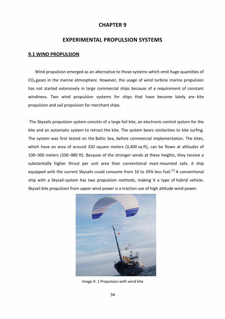
The Skysails propulsion system consists of a large foil kite, an electronic control system for the
kite and an automatic system to retract the kite. The system bears similarities to kite surfing.
The system was first tested on the Baltic Sea, before commercial implementation. The kites,
which have an area of around 320 square meters (3,400 sq ft), can be flown at altitudes of
100–300 meters (330–980 ft). Because of the stronger winds at these heights, they receive a
substantially higher thrust per unit area than conventional mast-mounted sails. A ship
equipped with the current Skysails could consume from 10 to 35% less fuel.[1] A conventional
ship with a Skysail-system has two propulsion methods, making it a type of hybrid vehicle.
Skysail kite propulsion from upper wind power is a traction use of high altitude wind power.
Image 9. 1 Propulsion with wind kite

35
9.2 FUEL CELL PROPULSION
A fuel cell is a device that converts the chemical energy from a fuel into electricity through
a chemical reaction with oxygen or another oxidizing agent. Hydrogen is the most common fuel,
but hydrocarbons such as natural gas and alcohols like methanol are sometimes used. Fuel cells
are different from batteries in that they require a constant source of fuel and oxygen to run, but
they can produce electricity continually for as long as these inputs are supplied.
Welsh Physicist William Grove developed the first crude fuel cells in 1839. The first commercial
use of fuel cells was in NASA space programs to generate power for probes, satellites and space
capsules. Since then, fuel cells have been used in many other applications. Fuel cells are used for
primary and backup power for commercial, industrial and residential buildings and in remote or
inaccessible areas. They are used to power fuel cell vehicles, including automobiles, buses,
forklifts, airplanes, boats, motorcycles and submarines.
There are many types of fuel cells, but they all consist of an anode (negative side),
a cathode (positive side) and an electrolyte that allows charges to move between the two sides of
the fuel cell. Electrons are drawn from the anode to the cathode through an external circuit,
producing direct current electricity. As the main difference among fuel cell types is the electrolyte,
fuel cells are classified by the type of electrolyte they use. Fuel cells come in a variety of sizes.
Individual fuel cells produce very small amounts of electricity, about 0.7 volts, so cells are
"stacked", or placed in series or parallel circuits, to increase the voltage and current output to
meet an application’s power generation requirements.
.
Image 9.2- fuel cell production

36
In addition to electricity, fuel cells produce water, heat and, depending on the fuel source, very
small amounts of nitrogen dioxide and other emissions. The energy efficiency of a fuel cell is
generally between 40-60%, or up to 85% efficient if waste heat is captured for use
9.3 SOLAR PROPULSION
Solar propulsion for ships was utilised for the first time in the year 2008. Solar
propulsion benefits include a high reduction in the poisonous carbon dioxide emissions. Solar
propulsions are capable of generating a capacitance as high as 40 kilowatts (kW).
Image 9.3- a model of a ship with solar propulsion system
9.4 GAS FUEL OR TRI FUEL PROPULSION
LNG fuel is now utilised to be burnt in the Main Engine after adopting some modification in the
propulsion engine to reduce emission from the ship. It is known as tri fuel because it can burn gas
fuel, diesel and heavy fuel.
Image 9.3- a LNG ship that consumes its cargo gases as fuel for her engine

37
The various types of propulsion systems offer their own unique advantages to a vessel. Depending
on the necessity and the requirement, the best type of ship propulsion system needs to be fitted.
Only then the vessel will be able to offer its optimum service capacitance.
9.5 MAGNETOHYDRONAMIC PROPULSION
A magnetohydrodynamic drive or MHD propulsion is a method for propelling seagoing
vessels using only electric and magnetic fields with no moving parts,
The working principle involves electrification of the propellant (gas or water) which can then be
directed by a magnetic field, pushing the vehicle in the opposite direction. Although some working
prototypes exist, MHD drivers remain impractical.
An electric current is passed through seawater in the presence of an intense magnetic field, which
interacts with the magnetic field of the current through the water. Functionally, the seawater is
then the moving, conductive part of an electric motor. Pushing the water out the back accelerates
the vehicle in the forward direction.
The physics equation describing this propelling force is Fmag = I (L × B) where L is the vector in the
direction of the current 'I' and its length is the distance the current travels, B is the magnetic field,
and × denotes the cross product.
MHD is attractive because it has no moving parts, which means that a good design might be silent,
reliable, efficient, and inexpensive.
Image 9.4- a magnetohydronamic vessel model

38
The major problem with MHD is that with current technologies it is more expensive and much
slower than a propeller driven by an engine. The extra expense is from the large generator that
must be driven by an engine. Such a large generator is not required when an engine directly.10
10 http://www.marineinsight.com/tech/main-engine/different-types-of-marine-propulsion-
systems-used-in-the-shipping-world/

39
CHAPTER 10
PROPULSION SYSTEMS LAYOUT
10.1 DEEP SEA VESSEL
Probably the most common propulsion set up out there. Look into any harbours, you will
most likely see ten ships (over 10,000 grt), and perhaps nine, if not all of them, will have this set
up. Bulk carriers, container ships, OBO, large fishing vessels, tankers and some cruise ships are
some vessels that use this setup.
The engine is generally a slow speed two stroke engine, such as a B&W or Sulzer. It is directly
connected to the propeller shaft. Forward thrust of the fixed pitch propeller is channelled to the
frames of the ship by the thrust block. Reverse is obtained by running the engine in reverse; they
are designed with a variable cam which allows this to happen. This set up is simple, efficient and
"easy" to operate and maintain.
Image 10.1- deep vessels propulsion system
10.2 SPECIALIZED VESSELS
This setup is very common on medium size specialized vessels, such as Stand By Vessels
(AHST) Research, cable ships and such. The CCGS Gordon Reid is a search and rescue vessel, it
features two of this of type of set up. The four engines and two shafts with CPPs offer a high
degree of redundancy and versatility. In the case of the Reid, the outside engines also drive fire
pumps feeding water to big fire monitors above the wheel house; as you would find on a oil rig
"stand by" vessel.
Two four stroke, medium speed engines are used here for their low size to power ratio. Having
two engines also offers a level of redundancy. They can be operated simultaneously or individually

40
because of the clutch. The gear box will compensate for the high speed of the engines and allow
the propeller to turn a more efficient slower speed. In the power range of typical four stroke
Diesels, the thrust bearing is usually fitted within the gear box, but occasionally it is an
independent fixture. The CPP system provides the quick response these types of vessels require.
Image 10.2- specialized vessels propulsion system
10.3 COASTAL VESSELS
This set up is common on larger fishing boats, coastal freighter; some medium size tugs
(~4000 hp). It is without mystery; the parts are easily serviceable because there usually "off the
shelf".
One four stroke medium speed Diesel engines which is geared and be run without turning the
shafting because of the clutch. The CPP offers a responsive level of control and reverse! The set up
is straight forward and easy to maintain.
Image 10.3- coastal vessels propulsion system

41
10.4 SMALL BOATS
This is typical set up of small vessels. Yacht, tugs, fishing boats, small ferries etc. It is very
common to see this in vessels having less than 2000 hp. It is very simple and the whole package is
pretty much "off the shelf".
The Diesel engine can be a two stroke (i.e. Detroit Diesel) or a four stroke (i.e. Cummins,
Caterpillar). It is almost always a high speed engine which requires the marine gear (i.e. Twin Disc).
The gear has a built in clutch, actually two clutches, one for forward and one to obtain reverse.
The gearbox also has the thrust bearing built in. The fix pitch propeller is attached to the end of
the shaft. This set up is very manageable and reliable.
Image 10.4- small boats propulsion system
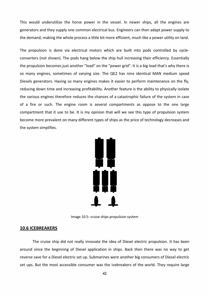
10.5 CRUISE SHIPS
The height of practical modern ship engineering is the Diesel electric cruise ship. Most of
the cruise ships are relatively new and most of them feature propulsion set up much like this one.
It offers more room for paying passengers; it is versatile and has a high degree of reliability. It is an
efficient system, as you can adapt supply power to your demand. It is technologically complex but
relatively easy to operate.
The engines are usually four stroke medium speed engines, this is because of their bigger size to
power ratio, so you don't need a big engine room space. In the past, you would have two big
engines to drive the vessel and three others to supply the large electrical hotel load.
42
This would underutilize the horse power in the vessel. In newer ships, all the engines are
generators and they supply one common electrical bus. Engineers can then adapt power supply to
the demand, making the whole process a little bit more efficient, much like a power utility on land.
The propulsion is done via electrical motors which are built into pods controlled by cycle-
converters (not shown). The pods hang below the ship hull increasing their efficiency. Essentially
the propulsion becomes just another "load" on the "power grid". It is a big load that's why there is
so many engines, sometimes of varying size. The QE2 has nine identical MAN medium speed
Diesels generators. Having so many engines makes it easier to perform maintenance on the fly,
reducing down time and increasing profitability. Another feature is the ability to physically isolate
the various engines therefore reduces the chances of a catastrophic failure of the system in case
of a fire or such. The engine room is several compartments as oppose to the one large
compartment that it use to be. It is my opinion that will we see this type of propulsion system
become more prevalent on many different types of ships as the price of technology decreases and
the system simplifies.
Image 10.5- cruise ships propulsion system
10.6 ICEBREAKERS
The cruise ship did not really innovate the idea of Diesel electric propulsion. It has been
around since the beginning of Diesel application in ships. Back then there was no way to get
reverse save for a Diesel electric set up. Submarines were another big consumers of Diesel electric
set ups. But the most accessible consumer was the icebreakers of the world. They require large

43
horse power but often encounter shock loading from hitting big pieces of ice and such. Diesel
engines do not appreciate shock loading.
The Diesel electric propulsion allowed the shocks to be "filtered" by the electrical machinery and
pass on to the engines in more manageable increments. The system illustrated here is from the
CCGS Sir Wilfrid Laurier, a Canadian medium icebreaker. It features three 2200 kW medium speed
V16 Alco 251. The AC generator feeds a common bus at 6600 VAC. The propulsion systems consist
of two electrical motors driving two fixed pitch propellers. Fixed pitch propellers and their
simplicity are less likely to fail in ice conditions as oppose to the more delicate CPP ones. The
motors are controlled by two cycle-converters. Cycle-converters are a web page unto themselves,
but basically, they allow the electric motors to turn, forward or reverse, at any given power
(speed) required.
Image 10.6b- ice-breaker propulsion system
10.7 NAVAL VESSELS AND TANKERS
Naval vessels and other military ships have other priorities than fuel efficiency. Therefore
we often see high powered propulsion set up in these vessels. That amount of power comes from
Image 10.6a- ice-breaker propulsion system

44
fuel thirsty gas turbines or steam turbines. The US navy is an avid consumer of steam plants - a
great number of their vessel obtains steam from nuclear means.
Traditional steam plants are still in operation but over the years the marine gas turbine has
become more prevalent for its power to weigh ratio (no need for a big boiler and its systems). In
Canada, our Halifax class frigates are power with gas turbines, but of course, we are not a rich
nation, so the propulsion plant also includes a more economical medium speed Diesel plant. In the
merchant marine, steam propulsion plants are relatively rare, as the Diesel engine can do the
same work more efficiently. Large tankers still use steam plants, this is due to the huge power
requirements that the Diesel engine has not been able to practically deliver.
Turbine plants are usually compact, "lightweight" high powered, and turn at a high rate of speed.
Their operation is simple but their maintenance and fuel consumption make sure it is not the most
popular choice for ship's propulsion. Above right, we see the military type set up. One gas turbine
and two cruising Diesels - medium speed four strokes. Each is capable of inputting power and that
power is controlled by a CPP. To the right we have a tanker steam turbine set up. As there is no
CPP, the steam turbine will have a reversing turbine built into each. The power feeds into the gear
box reducing the rpm, then into a fix pitch propeller.
10.8 DOUBLE ENDED FERRIES
The "double ender" ferry is another unique animal. It is quite common to see this type of
vessel in the North American northwest. BC and Washington state ferries use the double ender
ferries extensively. They carry large quantities of vehicles and passengers on short runs in calm
Image 10.7- naval and tankers vessels propulsion system

45
waters. To save the time of turning the vessel around at each berth, they just simply make sure it
goes easily one way as it does the other way.
This gives rise to an interesting design; one propeller and rudder at each end of the vessel. The
actual propulsion equipment is not that complicated. Take for example the BC Ferries Queen of
Cowichan. It has two MAK 550 medium speed four stroke Diesel engines each producing about
6000 hp. They are couple to a gear box by two air operated clutches. The shafts are quite long, as
they must go to both ends of the ship down the centreline. CPP and the two rudders make this
vessel responsive. The ship has a service speed of 21 knots.11
Image 10.8- double ended ferries propulsion system
11
http://www.dieselduck.net/machine/02%20propulsion/propulsion_layout/propulsion_layout.htm
46
AUTHOR’S OPINION
Traditionally, big two-stroke slow-speed diesel engines are dominating in tankers seagoing
ships, in bulk carriers and in the container seagoing ships. Respectively middle-speed diesel
engines are dominating in smaller merchant ships, such as ro-ro ships, cruise ships, passenger
ships and in ships of special use like reefer ships and ice-breakers. In early years there was a
distinction between the uses of those two engines. But now this is not happening anymore. Today
we can find two-stroke diesel engines in small passenger ships and there are new powerful four-
stroke diesel engines that can be found in ships that were using only two-stroke engines in the
past. Therefore it’s obvious that the choice for the type of a ship’s engine should be based on
techno-economic criteria and not the status of the past.
The reasons that led to the domination of two-stroke engines were their ability to consume low
quality fuel, without the need of regular maintenance.
Many ship owners prefer specific types of engines, because they depend on their reliability, the
familiarity of the crew with the specific types of engines, the available network of spare parts and
the special relationship with the supplier company. So there are limits in their choices because
there are still some standards that can prevail and make this decision more difficult.
The personnel is also an important factor for the choice of the engines that are big because they
have high number of parts and it is more possible to break down, and is more difficult to get
maintained. Furthermore the problems are increasing so the cost of the spare parts also.
Meanwhile the knowledge of the crew in engine room is reduced so the construction of simpler
engines is necessary.
As years pass technology achieves new developments. So through time we have proceeded from
sails to the most powerful engines MC and ME and from paddles to completely automatic
controllable pitch propellers. Although the field of propulsion is getting expanded, so it can reach
the best possible efficiency and lead the merchant and the battle navy in new solution for their
movement across the seas with new and completely advanced engines and machineries.
There are many marine diesel engines manufacturers. In the following charts, the most popular of
them will be displayed and their domination in merchant marine ships.

47
The most popular two-stroke engine manufacturing companies that ships are using, for their propulsion
The most polpular four-stroke engines manufacturing companies that ships are using for, their
propulsion or for their electric production

48
As we can see from the charts MAN B&W is dominating between all companies that manufacture
two-stroke engines. That is because through the years it has been proven the most reliable and
the most resourceful when at the same time SULZER (once, now WARTZILA-SULZER after their
merge) lost its prestige, to MAN B&W because it stopped producing its own series of engines with
exhaust ports and bought the rights for using the exhaust valve system from MAN.
Also MITSUBISHI is still dominant, with only few of shipping companies choosing them for their
ships. MITSUBISHI is constructing itsmodels exclusive in Japanese factories and uses its own turbo
chargers models.
As for four-stroke engines, we can see that three companies are in the same league, with
YANMAR proving herself as a very reliable company, due to the simple construction of her models
and the high efficiency of them. MAN and WARTZILA are in the same level when it comes to four-
stroke engines, with both of them adding continuously new innovations to their models. Last
SEMT-Pielstic once powerful in the area of four-stoke engines now is disappearing as it designs
only on specific models.

49
Bibliography:
Basic ship propulsion by J.P GHOSE and R.P GORKAN 2004, published by Allied Publishers
Pvt.Limited (pages 1-3)
Diesel engine design by H. F. P. PURDAY published by Constable, 1948 5th edition (pages
201-210, 226-233, 267-277, 280-285)
Marine Propellers and Propulsion by JOHN CARTLON 2007, published by Elsevier Ltd.
(pages 1-10, 11-13, 20-23, 205-207)
Internal combustion engines volume 2 2008, published by Institute Eugenidou (pages 99-
103, 105-108, 119-120)
Marine English notes (semester E’)
Sources:
internet
http://www.marineinsight.com/tech/main-engine/different-types-of-marine-propulsion-systems-
used-in-the-shipping-world/
http://www.dieselduck.net/machine/02%20propulsion/propulsion_layout/propulsion_lay
out.htm

50
INDEX
ABSTRACT ………………………..1
INTRODUCTION ………………………..2
CHAPTER 1: PROPULSION SYSTEMS IN GENERAL ………………………..
CHAPTER 2: THE MAIN PARTS OF THE PROPULSION SYSTEMS ………………………..5
CHAPTER 3: HOW DOES A PROPULSION SYSTEM WORK ………………………..
CHAPTER 4: THE MAIN POWER IN PROPULSION SYSTEMS ………………………..8
4.1 Reciprocation steam engines ………………………..8
4.2 Reciprocation diesel engines ………………………..9
4.3 Steam turbines ……………………...12
4.4 Gas turbines ……………………...1
4.5 Nuclear-powered steam turbines ……………………...15
CHAPTER 5: THE PROPELLERS ……………………...18
5.1 The types of propellers ……………………...19
5.2 Cavitation ……………………...2
CHAPTER 6: MAIN PRINCIPALS AND EQUIPMENT OF PROPULSION
SYSTEM FACILITIES
……………………...25
6.1 Joints ……………………...25
6.2 Reduction gears ……………………...2
6.3 Thrust block ……………………...27
6.4 Shaft bearing ……………………...27
6.5 Stern tube bearing ……………………...28
6.6 Stern tube seals ……………………...29

CHAPTER 7: DIESEL-ELECTRIC PROPULSION ……………………...
CHAPTER 8: NON CONVENTIONAL PROPULSION SYSTEMS ……………………... 2
8.1 Steerable azimuth drive system ……………………...
8.2 Water jet propulsion ……………………...
CHAPTER 9: EXPERIMENTAL PROPULSION SYSTEMS ……………………... 4
9.1 Wind propulsion ……………………... 4
9.2 Fuel cells propulsion ……………………... 5
9.3 Solar propulsion ……………………...
9.4 Gas fuel or tri fuel propulsión ……………………...
9.5 Magnetohydronamic propulsion ……………………... 7
CHAPTER 10: PROPULSION SYSTEMS LAYOUT ……………………... 9
10.1 Deep sea vessels ……………………... 9
10.2 Specialized vessels ……………………... 9
10.3 Coastal vessels ……………………...4
10.4 Small boat ……………………...41
10.5 Cruise ships ……………………...41
10.6 Icebreakers ……………………...42
10.7 Naval vessels and tankers ……………………...4
10.8 Double ended ferries ……………………...44
AUTHORS OPNINION ……………………...4
BIBLIOGRAPHY AND SOURCES ……………………...49