
MERCHANDISER FLEXIBLE ISLAND ISLA - Hussmann Documents/IM-R_io_En.pdf · 2 /CHINO A publication of...
73
ISLA FLEXIBLE ISLAND MERCHANDISER INSTALLATION & OPERATION GUIDE /CHINO ISLA FLEXIBLE ISLAND MERCHANDISER REV. 0317 Installation & Operation Manual
Transcript of MERCHANDISER FLEXIBLE ISLAND ISLA - Hussmann Documents/IM-R_io_En.pdf · 2 /CHINO A publication of...

ISLA
FL
EX
IBL
E IS
LA
ND
ME
RC
HA
ND
ISE
R
INS
TA
LL
AT
ION
& O
PE
RA
TIO
N G
UID
E
/CHINO
ISLA
FLEXIBLE ISLAND
MERCHANDISER
REV. 0317
Installation
& Operation
Manual

2
/CHINOA publication of HUSSMANN® Chino
13770 Ramona Avenue • Chino, California 91710
(909) 628-8942 FAX
(909) 590-4910
(800) 395-9229
www.hussmann.com
1. General Instructions
This Booklet Contains Information on:
ISLA A multi deck air curtain Self-Service case designed to display pre-packaged Deli,
Bakery, Meat, Seafood, and/or Beverage products.
Shipping Damage
All equipment should be thoroughly examined for shipping damage before and during
unloading.
This equipment has been carefully inspected at our factory and the carrier has assumed
responsibility for safe arrival. If damaged, either apparent or concealed, claim must
be made to the carrier.
Apparent Loss or Damage
If there is an obvious loss or damage, it must be noted on the freight bill or express
receipt and signed by the carrier’s agent; otherwise, carrier may refuse claim. The
carrier will supply necessary claim forms.
Concealed Loss or Damage
When loss or damage is not apparent until after all equipment is uncrated, a claim for
concealed damage is made. Make request in writing to carrier for inspection within 15
days, and retain all packaging. The carrier will supply inspection report and required
claim forms.
Shortages
Check your shipment for any possible shortages of material. If a shortage should exist
and is found to be the responsibility of Hussmann Chino, notify Hussmann Chino. If
such a shortage involves the carrier, notify the carrier immediately, and request an
inspection. Hussmann Chino will acknowledge shortages within ten days from receipt
of equipment.
Hussmann Chino Product Control
The serial number and shipping date of all equipment has been recorded in Hussmann’s
fi les for warranty and replacement part purposes. All correspondence pertaining to
warranty or parts ordering must include the serial number of each piece of equipment
involved, in order to provide the customer with the correct parts.
Keep this booklet with the case at all times for future reference.

3
2. Table of Contents
1. General Instructions...............................................................2
2. Table of Contents ...................................................................2
3. Cut and Plan Views ................................................................4
4. Installation...............................................................................5
5. Plumbing ...............................................................................14
6. Refrigeration .........................................................................19
7. Electrical................................................................................21
8. Electrical Wiring Diagrams Index ........................................34
9. Electrical Wiring Diagrams .................................................35
10.User Information ..................................................................64
11. Shelf Weight Limits ............................................................65
12. Maintenance ........................................................................66
Maintenance (Cont'd) ...............................................................67
13. Troubleshooting Guide ......................................................68
14. Appendices .........................................................................70
Appendix A. - Temperature Guidelines ............................................................................................ 70
Appendix B. - Application Recommendations ................................................................................ 70
Appendix C. - Field Recommendations............................................................................................ 70
Appendix D. - Recommendations to User........................................................................................ 71

4
3. Cut and Plan Views
10 1/8(257)
6 7/8(175)
50(1270)
253/8 (645)
161/8 (410)
217/8 (556)
341/4 (794)
47 3/8(1203)
293/4(756)
311/4(794)
IM-04-ED5-R Deeper base, Extended Canopy
6 3/4(171)
375/8(956)
391/4(997)
6 3/4(171)
6 3/4(171)
6 3/4(171)
5 5/8(143)
10 1/8(257)
6 7/8(175)
Center Module (C) Inline and End Module (I, E)
33 5/8(854)
35 3/8(899)
58(1473)
10(254)
12(305)
14(356)
16(406)
22(559)
IM-05-R Refrigerated Self-Service Module
213/4 (552)
35 3/8(899)
28 1/2(724)
Elec
CL
201/4(514)
135/8(346)
207/8 (530) 25 (635)
67 1/4(1708)
IM-C5-R Center Module / IM-I5-R In-line Module
60(1524)
5(127)
RefrigDrain
17 1/8(435)
153/8 (391)
17 (432)
Elec
CL
185/8(473)
201/4(514)
117/8 (302)
131/2 (343)
Refrig
Drain35 3/8(899)
33 5/8(854)
9 1/8(232)
EndPanel
1 1/8(29)
WrapAround
End
3 5/8(90)
IM-04-E5-R, IM-05-E5-R End Module
63/8(162)
63/8(162)
63/8(162)
61/8(156)
10 1/8(257)
6 7/8(175)
50(1270)
10(254)
12(305)
14(356)
22(559)
Center Module (C) Inline and End Module (I, E)
33 5/8(854)
35 3/8(899)
293/4(756)
311/4(794)
213/4 (552)
IM-04-R Refrigerated Self-Service Module

5
LocationThe refrigerated merchandisers have been designed
for use only in air conditioned stores where temperature
and humidity are maintained at or below 75°F and 55%
relative humidity. DO NOT allow air conditioning, electric
fans, ovens, open doors or windows (etc.) to create air
currents around the merchandiser, as this will impair its
correct operation.
DO NOT place Self Contained versions
of this case, having the electric evaporator pan,
underneath or adjacent to any flammable structure
or structure housing flammable merchandise!
DANGER
Uncrating the StandPlace the fi xture as close to its permanent position as
possible. Remove the top of the crate. Detach the walls
from each other and remove from the skid. Unbolt the
case from the skid. The fi xture can now be lifted off the
crate skid. Lift only at base of stand!
Exterior LoadingThese models have not been structurally designed to
support excessive external loading. Do not walk on
their tops; This could cause serious personal injury and
damage to the fi xture.
Setting and JoiningThe sectional construction of these models enable them
to be joined in line to give the effect of one continuous
display. A joint trim kit is supplied with each joint.
It is the contractor’s responsibility to install
case(s) according to local construction and
health codes.
ATTENTIONINSTALLER
LevelingIMPORTANT! IT IS IMPERATIVE THAT CASES
BE LEVELED FROM FRONT TO BACK AND SIDE
TO SIDE PRIOR TO JOINING. A LEVEL CASE IS
NECESSARY TO INSURE PROPER OPERATION,
WATER DRAINAGE, GLASS ALIGNMENT AND
OPERATION OF THE HINGES SUPPORTING THE
GLASS. LEVELING THE CASE CORRECTLY WILL
SOLVE MOST HINGE OPERATION PROBLEMS.
Note: A. To avoid removing concrete fl ooring, begin lineup
leveling from the highest point of the store fl oor.
B. When wedges are involved in a lineup, set them fi rst.
ISLA Body Panel Removal and
Installation
Transportation:
All Lower and Bottom Body panels on the ISLA should
be removed for extended transportation (jacking, lifting,
crating, etc.)
Service:
For most service applications (drains, piping, electrical),
only the Bottom Body panels need removal. Removing
both panels may be more convenient.
Note: The Bumper and Price Tag Extrusion should only be
serviced by a trained installation professional. Incorrect
servicing will result in damage.
4. Installation

6
Installation (Cont'd)ISLA Lifting and Transport Instructions
6.000"
12. 000"
6.000"
12.000"
LIFT /RAISE
ZONE
30.031"
18.031"
18.031"
33.675 "
1. The ISLA can be lifted by a forklift only at the specifi ed location in the diagram
Improper placement of forks may damage
drainage piping. Use a spotter when placing forks.
Make sure that piping will not be damaged.
Use J-Bars or Jacks if Forks cannot be used safely
WARNING
2. Remove close-offs and lower body panels before lifting with a fork. Serious damage will occur if the body panels
are not removed.
• Remove the end case lower and bottom panels fi rst
• Then remove the side case lower and bottom panels
• A Phillips head screwdriver/drill is needed for lower and bottom panel removal
3. Make sure that fork spacing and width will not damage drain, piping, or electrical lines
4. Be sure that the forks are long enough to support beyond the center of the case. Check for proper balance before
moving. A minimum fork length of 36” is recommended for 68” wide cases
5. The ISLA can be raised at one end with a forklift to allow the placement of rollers or dollies. See fi gure on page 13
for J-bar and jacking instructions
6. Never drag or push the ISLA by ANY COMPONENT including ANY GLASS COMPONENT. This will result in
damage to the base, and possibly damage to other components
7. Evenly support the entire base structure on rollers or dollies before attempting to move.

7
Installation (Cont'd)
33.675"
6.000" 6.000 "
J-BAR JACKING POINT
8. If using J-Bars, use the specifi ed jacking points to raise the case
• Raise one side of the case fi rst.
• Use as many J-Bars as possible to lift from the base channels
• A minimum of 2 J-Bars is required
• Place Dollies and chock wheels before lifting the other side. Be sure that the dollies are evenly spaced to
carry to weight of the case
FLOOR JACK/BOTTLE JACK
LIFTING POINTSLIFTING POINT LIFTING POINT
LIFTING POINT LIFTING POINT
9. If using Floor-jacks or Bottle-jacks, use the recommended lifting points located at the underside of the case
• These points will be visible channels
• Lift simultaneously to place dollies or rollers

8
Installation (Cont'd)

9
Installation (Cont'd)
10
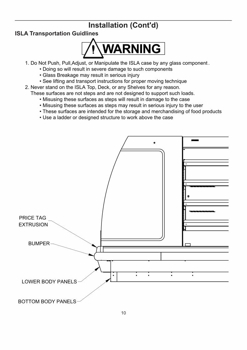
Installation (Cont'd)ISLA Transportation Guidlines
1. Do Not Push, Pull,Adjust, or Manipulate the ISLA case by any glass component .
• Doing so will result in severe damage to such components
• Glass Breakage may result in serious injury
• See lifting and transport instructions for proper moving technique
2. Never stand on the ISLA Top, Deck, or any Shelves for any reason.
These surfaces are not steps and are not designed to support such loads.
• Misusing these surfaces as steps will result in damage to the case
• Misusing these surfaces as steps may result in serious injury to the user
• These surfaces are intended for the storage and merchandising of food products
• Use a ladder or designed structure to work above the case
WARNING
BOTTOM BODY PANELS
LOWER BODY PANELS
BUMPER
PRICE TAG
EXTRUSION

11
Installation (Cont'd)
1. Remove screws holding
panels at both side
2. Remove screws holding
panels at the ends
3. Remove body panels
from both ends before
attempting to remove
side body panels
move
Note: The Lower and Bottom body panels can be removed independent of each other
4. Repeat steps 1-3
for the side panels
5. For installation,
reverse the procedure.
Make sure the side panels
are installed first.
The end body
panels will encapsulate
the side panels
Note that lower side of the
lower body panels must be
properly placed around mounting
surface to ensure proper fit.

12
Installation (Cont'd)ISLA Sump Pump Service Instructions
Note: Before attempting to service the sump pump and drain components, refer to the ISLA BODY PANEL REMOVAL and
INSTALLATION GUIDE.
The Bottom (and possibly Lower) panels must be removed to allow access for servicing.
The Drain Sump will be full of drainwater. Use the appropriate Personal Protective Equipment (Gloves, Goggles, Sleeves, etc.)
during removal.
Sump Drain
Assembly Tray
Sump Drain
Collector Pan
Sump Drain
Pump
Sump Drain
Outlet
Base
Legs
Base
Runners
Drain Trap
Assembly
Drain Piping
(To Collector Pan)

13
Installation (Cont'd)Note: The drainage system is always active, but sees most activity during defrost. If the refrigeration cannot be stopped, work on the
drainage system between defrost periods.
2. Lift and remove
(4) drain pipes from
collector pan
Use a basin or shallow
container as temporary
sump while servicing.
3. Disconnect sump drain
outlet from pump
The fitting will be either
barbed or hose clamp
1. Unplug Sump Pump (Not Pictured)
WARNING:
Servicing the drainage system
with the sump pump energized
may result in electrical shock!
4. Slide Collector pan
out from Assembly Tray
5. Empty collector pan and clear
debris
Wash with soapy water
Add condensate pan treatment
tablet after each wash
(e.g. Pro Treat 151 tablets)
.
6. Reverse procedure to
reassemble

14
5. Plumbing
Waste Outlet and P-TRAPThe waste outlet is located in the center, 8" from the
front of the case.
A 1 1/2" P-TRAP and threaded adapter are supplied with
each fi xture. The P-TRAP must be installed to prevent
air leakage and insect entrance into the fi xture.
NOTE: PVC-DWV solvent cement is recommended. Follow the
Hussmann’s instructions.
Installing Condensate DrainPoorly or improperly installed condensate drains can
seriously interfere with the operation of this refrigerator
and result in costly maintenance and product losses.
Please follow the recommendations listed below
when installing condensate drains to insure a proper
installation:
1. Never use pipe for condensate drains smaller
than the nominal diameter of the pipe or P-TRAP
supplied with the case.
2. When connecting condensate drains, the P-TRAP
must be used as part of the condensate drain
to prevent air leakage or insect entrance. Store
plumbing system fl oor drains should be at least 14"
off the center of the case to allow use of the P-TRAP
pipe section. Never use two water seals in series in
any one line. Double P-TRAPS in series will cause a
lock and prevent draining.
3. Always provide as much down hill slope ("fall") as
possible; 1/8" per foot is the preferred minimum.
PVC pipe, when used, must be supported to
maintain the 1/8" pitch and to prevent warping.
4. Avoid long runs of condensate drains. Long runs
make it impossible to provide the "fall" necessary for
good drainage.
5. Provide a suitable air break between the fl ood rim of
the fl oor drain and outlet of condensate drain. 1" is
ideal.
6. Prevent condensate drains from freezing:
a. Do not install condensate drains in contact
with non-insulated suction lines. Suction lines
should be insulated with a nonabsorbent
insulation material such as Armstrong's
Armafl ex.
b. Where condensate drains are located in dead
air spaces (between refrigerators or between
a refrigerator and a wall), provide means to
prevent freezing. The water seal should be
insulated to prevent condensation.
ISLA (Self Contained)The waste outlet and P-TRAP are the same as the
remote except hot air from the condenser is forced
through the water evap assembly, evaporating the water.

15
MATERIAL : PART # LB BLANK SIZE :
PART # :
DWG DIR :
REF PRINT :
REV DCR DATE BY: ?Site specific text field not to conflict with ISO
standards.
Including standards ISO7200, ISO128, and
ISO5457. Chino
5/18/2009 mgillett
ISLA
5/18/2009
ISLA ASSEMBLIESISLA TOP STUB PIPING DIAGRAMISLA 04/05
Refrigeration, Electrical, Sump Drain
Optional Top Stub Location
Suction Line7/8" Copper
Liquid Line3/8" Copper
Thermal
Expansion
Valve
Evap
ora
tor
Evaporator
Evaporator
Evap
ora
tor
Thermal
Expansion
Valve
Thermal
Expansion
Valve
Thermal
Expansion
Valve
Plu
mb
ing
(Co
nt'd
)

16
MATERIAL : PART # LB BLANK SIZE :
PART # :
REF PRINT :
?
Chino
5/18/2009
ISLA
5/18/2009
ISLA 04/05
Liquid Line
Suction Line
REV DCR DATE BY:Site specific text field not to conflict with ISO
standards.
Including standards ISO7200, ISO128, and
ISO5457.
ISLA TOP STUB PIPING DIAGRAMISLA ASSEMBLIES
mgillett
DWG DIR :
Plu
mb
ing
(Co
nt'd
)

17
MATERIAL : PART # LB BLANK SIZE :
PART # :
DWG DIR :
REF PRINT :
REV DCR DATE BY: ?Site specific text field not to conflict with ISO standards.Including standards ISO7200, ISO128, and ISO5457. Chino
5/18/2009 mgillett
ISLA
5/18/2009
ISLA ASSEMBLIESISLA 04/05
Sump Pump
Drain Outlet*
(Discharges Through
Topside Drain Stub)
Drain Sump Pump*
3/4" PVC Drain Pipe
*Note: Pan and Pump Location
may be different from indicated
depending on base legs.
Sump DrainTop Stub Location
DrainP-Trap/Run-Trap
Drain Sump Pan*
ISLA TOP STUB PIPING DIAGRAM
Plu
mb
ing
(Co
nt'd
)

18
Plu
mb
ing
(Co
nt'd
)
MATERIAL : PART # LB BLANK SIZE :
PART # :
DWG DIR :
REF PRINT :
REV DCR DATE BY: ?
Chino
5/18/2009 mgillett
ISLA
5/18/2009
ISLA 04/05
Sump Pump Drain Outlet Hose
Drain Water
Collects in
Removable Sump
(Periodic Cleaning Required)
P-TraporRun Trap
All DrainsLead toSump
Pump Site in Sump
ISLA TOP STUB PIPING DIAGRAMISLA ASSEMBLIES
Site specific text field not to conflict with ISO
standards.
Including standards ISO7200, ISO128, and
ISO5457.

19
6. RefrigerationRefrigerant TypeThe standard refrigerant will be R-404A unless otherwise
specifi ed on the customer order. Check the serial plate
on the case for information.
PipingThe refrigerant line outlets are located under the case.
Locate fi rst the electrical box, the outlets are then on the
same side of the case, but at the opposite end. Insulate
suction lines to prevent condensation drippage.
Refrigeration Lines Liquid Suction
3/8” O.D. 5/8” O.D.
NOTE: The standard coil is piped at 5/8" (suction); however,
the store tie-in may vary depending on the number
of coils and the draw the case has. Depending on the
case setup, the connecting point in the store may be
5/8”, 7/8”, or 11/8”. Refer to the particular case you are
hooking up.
Refrigerant lines should be sized as shown on the
refrigeration legend furnished by the store. Install P-
TRAPS (oil traps) at the base of all suction line vertical
risers. Pressure drop can rob the system of capacity. To
keep the pressure drop to a minimum, keep refrigerant
line run as short as possible, using the minimum number
of elbows. Where elbows are required, use long radius
elbows only.
Control SettingsMaintain these parameters to achieve near constant
product temperatures. Product temperature should
fi rst be measured in the morning, after having been
refrigerated overnight.
Access to TX Valves and Drain LinesMECHANICAL - Remove product from left end of case.
Remove product racks. Remove refrigeration and drain
access panels (labeled). TX valve (mechanical only) and
drain are located under the pans within the case.
ELECTRONIC - The electronic expansion valve master
and slave cylinder(s) are located within the electrical
access panel(s) in the rear of case. Rear panels lift up
and out.
Electronic Expansion Valve (Optional)A wide variety of electronic expansion valves and case
controllers can be utilized. Please refer to EEV and
controller Hussmann’s information sheet. Sensors for
electronic expansion valves will be installed on the
coil inlet, coil outlet and in the discharge air. (Some
supermarkets require a 4th sensor in the return air).
Case controllers will be located in the electrical raceway
or under the case.
Thermostatic Expansion Valve
LocationAn Alco balanced port expansion valve model is
furnished as standard equipment, unless otherwise
specifi ed by customer. There is one expansion valve
located on the right side of each evaporation coil under
the bottom deck pans.
Expansion Valve AdjustmentExpansion valves must be adjusted to fully feed the
evaporator. Before attempting any adjustments, make
sure the evaporator is either clear or very lightly covered
with frost, and that the fi xture is within 10°F of its
expected operating temperature.
Measuring the Operating Superheat1. Determine the suction pressure with an accurate
pressure gauge at the evaporator outlet.
2. From a refrigerant pressure temperature chart,
determine the saturation temperature at the
observed suction pressure.
3. Measure the temperature of the suction gas at the
thermostatic remote bulb location.
4. Subtract the saturation temperature obtained in step
No. 2 from the temperature measured in step No. 3.
5. The difference is superheat.
6. Set the superheat for 5°F - 7°F.
Condenser VentilationBe sure to Supply adequate ventilation for the condenser
in Self Contained units. Allow 150 square inches for units
up to 1 1/2 h.p., and 200 for condenser units over 2 h.p.

20
T-STAT Location (Remote cases only)
Remove front panel
Step 1: Removal of cover: With power off remove screws and pull cover off
Remove 4 screws
to gain access to
T-Stat behind panel.
Start-up
Self Contained (Safenet Controller)
On self contained cases the unit is completely charged
and tested to the proper temperature. Remove air grill
panel by lifting up and tilting out. Access electrical panel
by removing 4 screws. Turn on main switch at lower
right hand side of electrical box. Follow instructions for
Safenet startup on page 22.
Refrigeration (Cont'd)
Remote
After proper testing, evacuation and charging, set the
coil or evaporation temperature to 15°F by the method
engineered into your system. A thermostat is located on the
top of the case for temperature control. Set the thermostat
to cycle in and out as per the ISLA technical data sheet.

21
7. Electrical
Wiring Color Code
Standard Case Wire Color Code
Ground
Anti-Sweat
Lights
Receptacles
T-Stat/Solenoid 230VAC
T-Stat/Solenoid 115VAC
T-Stat/Solenoid 24VAC
Fan Motors
Blue Condensing Unit
Green
Purple
Orange
Yellow
Red/Black
White/Black
Red/White
Brown
Use Copper Conductors Only
430-01-0338 R101003
Color Decsription Color
CASE MUST BE GROUNDED
NOTE: Refer to label affi xed to case to determine the actual
confi guration as checked in the “TYPE INSTALLED”
boxes.
Electrical Circuit Identifi cationStandard lighting for all refrigerated models will be full
length fl uorescent lamps located within the case at the
top.
The switch controlling the lights, the plug provided for
digital scale, and the thermometer are located at the rear
of the case mullion.
The receptacle that is provided on the exterior back
of these models is intended for computerized scales
with a fi ve amp maximum load, not for large motors or
other high wattage appliances. It should be wired to a
dedicated circuit.
Field Wiring and Serial Plate
AmperageField Wiring must be sized for component amperes
printed on the serial plate. Actual ampere draw may be
less than specifi ed. Field wiring from the refrigeration
control panel to the merchandisers is required for
refrigeration thermostats. Case amperes are listed on
the wiring diagram, but always check the serial plate.
BEFORE SERVICING
ALWAYS DISCONNECT ELECTRICAL
POWER AT THE MAIN DISCONNECT
WHEN SERVICING OR REPLACING ANY
ELECTRICAL COMPONENT.
This includes (but not limited to) Fans, Heaters
Thermostats, and Lights
DANGER
.
LED Driver LocationDrivers are located within the access panel that runs the
length of the rear of the case.

22
Spec SheetMEDIUM TEMP MULTI-DECK ISLAND REVISION DATE 1/5/17
HUSSMANN - Isla - IM-04-(EN or CN)(XX)-R CASE MODULES (ISLA) (CHINO)
REFRIGERATION DATA:
GPM PSI
NSF 7AHRI
1200NSF 7 AHRI 1200 3' 0.7 0.9 0.7
3',4',5',6',8',10',12' 825 800 25 26 4' 1.0 1.2 1.4
3',4',5',6',8',10',12' 1000 800 21 26 5' 1.2 1.4 2.1
6' 1.4 1.7 1.2
**FRONT DISCHARGE AIR MEASURED INSIDE AIR CURTAIN HONEYCOMB 8' 2.0 2.2 2.0
***REFRIGERATION NOTES: 10' 2.5 2.8 2.9
1) BTU'S INCLUDE CANOPY LIGHTS. ADD 10 BTUS/SHELF/FT FOR EACH SHELF (LIGHT) 12' 2.9 3.3 2.7
2) MEAT CASE SPECS ARE FOR PACKAGED MEAT.
3) AHRI 1200 RATING POINT FOR ENERGY CONSUMPTION COMPARISON ONLY.
4) USE DEW POINT FOR HIGH GLIDE REFRIGERANTS. CARE SHOULD BE TAKEN TO USE THE DEW POINT IN P/T TABLES FOR MEASURING
AND ADJUSTING SUPERHEAT. ADJUST EVAPORATOR PRESSURE AS NEEDED TO MAINTAIN THE DISCHARGE AIR TEMPERATURE SHOWN.
5) RATING CONDITION IS NSF TYPE I, 75°F/55% RH
REFRIGERATION DATA CONTINUED:
1 1.125
2 1.125
DELI / DAIRY 33 30 OFF TIME 20 48 N/A
MEAT 31 28 OFF TIME 20 48 N/A
ELECTRICAL DATA:
STANDARD FANS, HEATERS, LED LIGHTS (115 VOLT)
3' 1 8 20 0.3 8 0.2 19 0.2 23 0.4 42 N/A N/A N/A N/A N/A4' 1 8 20 0.3 8 0.2 27 0.3 31 0.5 58 N/A N/A N/A N/A N/A5' 1 8 25 0.3 8 0.3 34 0.3 39 0.6 73 N/A N/A N/A N/A N/A6' 2 8 20 0.6 16 0.3 39 0.4 46 0.7 85 N/A N/A N/A N/A N/A8' 2 8 20 0.6 16 0.5 54 0.5 62 1.0 116 N/A N/A N/A N/A N/A10' 2 8 25 0.6 16 0.6 68 0.7 78 1.3 146 N/A N/A N/A N/A N/A12' 3 8 20 0.9 24 0.7 81 0.8 93 1.5 173 N/A N/A N/A N/A N/A
OPTIONAL HIGH OUTPUT LED LIGHTS (115 VOLT)
CASE ENERGY USAGE DATA:
AMPS WATTS AMPS WATTS AMPS WATTS
3' 0.2 24 0.3 39 0.5 634' 0.3 32 0.4 46 0.7 785' N/A N/A N/A N/A N/A N/A6' 0.4 47 0.7 78 1.1 1258' 0.6 64 0.8 91 1.3 15510' N/A N/A N/A N/A N/A N/A
12' N/A N/A N/A N/A N/A N/A
WATTS AMPS
USAGE
DEFROST
TYPE
TIME
(MIN)
DEFROST
FREQUENCY
(#/DAY)
AMPS
EVAPORATOR FANSCANOPY LIGHTS
LED
OPTIONAL LED
SHELF LIGHTS
CASE LENGTH # OF
EVAP
FANS
BLADE
DIA.
(IN.)
BLADE
PITCH (°)AMPS WATTS
3',4',5',6',8',10',12' 2.65 1.90 2.01
ANTI-SWEAT
HEATERS (ON FAN
CIRCUIT)
CONVENIENCE
OUTLETS (OPTIONAL)
TDA/V (ft2/ft)
ACTUAL CDEC
(KWh/day/ft)
MAX
ALLOWABLE
CDEC
(KWh/Day/ft)
MAX. LED LOAD
(W/ ALL OPTIONS)
#
OUTLETSVOLTS AMPSWATTSWATTS AMPS
CASE LENGTH
CANOPY
LIGHTS
H.O. LED
OPTIONAL SHELFMAX. H.O. LED
LOADCASE LENGTH
AMPS WATTS
2.25
DELI / DAIRY 30~32 150~250
MEAT 28~30 150~250
END PANEL WIDTH KEY
1.125
# OF
END
PNLS
END PNL
WIDTH
(IN.)
TOTAL ADDED
LENGTH (IN.)CUT
IN (ºF)
CUT
OUT
(ºF)
ELEC. THERMOSTAT / AIR
SENSOR SETTINGS
EST.
REFG.
CHRG.
(R404A)
(LBS)
GLYCOL (20°F
INLET, 6°
RISE)
RATING CONDITION EVAPORATOR DISCHARGE
AIR ** (°F)
CASE
LENGT
HSCASE LENGTHS CASE USAGE
CAPACITY ***
(BTU/HR/FT)TEMPERATURE (ºF)
VELOCITY
(FT/MIN)
6
6
NSF 7 NSF 7
DRIP
TIME
DEFROST
WATER
(LBS/DAY/FT)
6.0
7.0
TERM.
TEMP
(°F)
COIL
ONLY

23
Spec Sheet (Cont'd)MEDIUM TEMP MULTI-DECK ISLAND REVISION DATE 1/5/17
HUSSMANN Isla - IM-04-(E or C)(XX)-R CASE MODULES (ISLA) (CHINO)
REFRIGERATION DATA:
GPM PSI
3' 0.7 0.9 0.74' 1.0 1.2 1.4
3',4',5',6',8',10',12' 800 800 25 25 5' 1.2 1.4 2.13',4',5',6',8',10',12' 1130 800 21 25 6' 1.4 1.7 1.2
8' 2.0 2.3 2.0**FRONT DISCHARGE AIR MEASURED INSIDE AIR CURTAIN HONEYCOMB 10' 2.5 2.8 2.9***REFRIGERATION NOTES: 12' 2.9 3.3 2.7
1) BTU/HR/FT INCLUDE 1 ROW CANOPY LED LIGHTING. ADD 10 BTUS/SHELF/FT FOR EACH SHELF (LIGHT)2) MEAT CASE SPECS ARE FOR PACKAGED MEAT.3) AHRI 1200 RATING POINT FOR ENERGY CONSUMPTION COMPARISON ONLY4) USE DEW POINT FOR HIGH GLIDE REFRIGERANTS. CARE SHOULD BE TAKEN TO USE THE DEW POINT IN P/T TABLES FOR MEASURING AND ADJUSTING SUPERHEAT. ADJUST EVAPORATOR PRESSURE AS NEEDED TO MAINTAIN THE DISCHARGE AIR TEMPERATURE SHOWN.5) RATING CONDITION IS NSF TYPE I, 75°F/55% RH
REFRIGERATION DATA CONTINUED:
1 1.125
2 1.125
DELI / DAIRY 33 30 OFF TIME 20 48 N/A
MEAT 31 28 OFF TIME 20 48 N/A
ELECTRICAL DATA:
STANDARD FANS, HEATERS, LED LIGHTS (115 VOLT)
AMPS WATTS AMPS WATTS AMPS WATTS AMPS WATTS#
OUTLETSVOLTS AMPS
3' 1 8 20 0.3 8 0.2 19 0.2 23 0.4 42 N/A N/A N/A N/A N/A4' 1 8 25 0.3 8 0.2 27 0.3 31 0.5 58 N/A N/A N/A N/A N/A5' 1 8 30 0.3 8 0.3 34 0.3 39 0.6 73 N/A N/A N/A N/A N/A6' 2 8 20 0.6 16 0.3 39 0.4 46 0.7 85 N/A N/A N/A N/A N/A8' 2 8 25 0.6 16 0.5 54 0.5 62 1.0 116 N/A N/A N/A N/A N/A
10' 2 8 30 0.6 16 0.6 68 0.7 78 1.3 146 N/A N/A N/A N/A N/A12' 3 8 25 0.9 24 0.7 81 0.8 93 1.5 173 N/A N/A N/A N/A N/A
OPTIONAL HIGH OUTPUT LED LIGHTS (115 VOLT)
CASE ENERGY USAGE DATA:
AMPS WATTS AMPS WATTS AMPS WATTS3' 0.2 24 0.3 39 0.5 634' 0.3 32 0.4 46 0.7 785' N/A N/A N/A N/A N/A N/A6' 0.4 47 0.7 78 1.1 1258' 0.6 64 0.8 91 1.3 155
10' N/A N/A N/A N/A N/A N/A
12' N/A N/A N/A N/A N/A N/A
CONVENIENCE
OUTLETS (OPTIONAL)
LED CANOPY
LIGHTS
LED SHELF
LIGHTS
MAX. LED LOAD
(W/ ALL OPTIONS)
ANTI-SWEAT
HEATERS (ON FAN
CIRCUIT)CASE LENGTH
EVAPORATOR FANS
# OF
EVAP
FANS
BLADE
DIA. (IN.)
BLADE
PITCH (°)AMPS WATTS
USAGECUT IN
(ºF)
CUT
OUT
(ºF)
TERM.
TEMP
(°F)
COIL
ONLY
DRIP
TIME
ELEC. THERMOSTAT / AIR
SENSOR SETTINGSDEFROST
FREQUENCY
(#/DAY)
DEFROST
TYPE
TIME
(MIN)
NSF 7
CASE LENGTHS CASE USAGE
NSF 7AHRI
1200NSF 7 AHRI 1200 NSF 7
EST.
REFG.
CHRG.
404A (LBS)
GLYCOL (20°F
INLET, 6° RISE)
RATING
CONDITIONEVAPORATOR
DISCHARGE
AIR ** (°F)
CASE
LENGTHS
CAPACITY ***
(BTU/HR/FT)TEMPERATURE (ºF)
VELOCITY
(FT/MIN)
2.25
MEAT 25~30 150~250DELI / DAIRY 30~35 150~250
END PANEL WIDTH KEY# OF END
PNLS
END PNL
WIDTH
TOTAL ADDED
LENGTH (IN.)
1.125
CASE LENGTH
3',4',5',6',8',10',12' 2.76 1.98 2.09
TDA/V (ft2/ft)
ACTUAL CDEC
(KWh/day/ft)
MAX
ALLOWABLE
CDEC
CASE LENGTH
CANOPY
LIGHTS
H.O. LED
SHELF LIGHTS
H.O. LED
MAX. H.O. LED
LOAD
6
6
DEFROST
WATER
(LBS/DAY/FT)
6.0
7.0

24
MEDIUM TEMP MULTI-DECK FLORAL ISLAND REVISION DATE 1/5/17
HUSSMANN - Isla - IM-04-(E or C)(XX)-R-F CASE MODULES (ISLA) (CHINO)
REFRIGERATION DATA:
GPM PSI
NSF 7 AHRI 1200 NSF 7 AHRI 1200 3' 0.7 0.6 0.4
4' 1.0 0.9 0.95' 1.2 1.0 1.46' 1.4 1.2 0.8
**FRONT DISCHARGE AIR MEASURED INSIDE AIR CURTAIN HONEYCOMB 8' 2.0 1.6 1.4***REFRIGERATION NOTES: 10' 2.5 2.0 2.0
1) BTU'S INCLUDE 1 ROW CANOPY LED LIGHTS AND NO SHELF LIGHTS 12' 2.9 2.4 1.82) AHRI 1200 RATING POINT FOR ENERGY CONSUMPTION COMPARISON ONLY
3) USE DEW POINT FOR HIGH GLIDE REFRIGERANTS. CARE SHOULD BE TAKEN TO USE THE DEW POINT IN P/T TABLES
FOR MEASURING AND ADJUSTING SUPERHEAT. ADJUST EVAPORATOR PRESSURE AS NEEDED TO MAINTAIN THE
DISCHARGE AIR TEMPERATURE SHOWN.
4) RATING CONDITION IS NSF TYPE I, 75°F/55% RH
REFRIGERATION DATA CONTINUED:
1 1.125
2 1.125
FLORAL 36 33 OFF TIME 20 54 N/A
ELECTRICAL DATA:
STANDARD FANS, HEATERS, LED LIGHTS (115 VOLT)
# OF
EVAP
FANS
BLADE
DIA. (IN.)
BLADE
PITCH (°)AMPS WATTS AMPS WATTS AMPS WATTS AMPS WATTS AMPS WATTS
#
OUTLETSVOLTS AMPS
3' 1 8 20 0.3 8 0.2 19 N/A N/A 0.2 19 N/A N/A N/A N/A N/A4' 1 8 25 0.3 8 0.2 27 N/A N/A 0.2 27 N/A N/A N/A N/A N/A5' 1 8 30 0.3 8 0.3 34 N/A N/A 0.3 34 N/A N/A N/A N/A N/A6' 2 8 20 0.6 16 0.3 39 N/A N/A 0.3 39 N/A N/A N/A N/A N/A8' 2 8 25 0.6 16 0.5 54 N/A N/A 0.5 54 N/A N/A N/A N/A N/A
10' 2 8 30 0.6 16 0.6 68 N/A N/A 0.6 68 N/A N/A N/A N/A N/A12' 3 8 25 0.9 24 0.7 81 N/A N/A 0.7 81 N/A N/A N/A N/A N/A
OPTIONAL HIGH OUTPUT LED LIGHTS (115 VOLT)
CASE ENERGY USAGE DATA:
AMPS WATTS AMPS WATTS AMPS WATTS
3' 0.2 24 N/A N/A 0.2 244' 0.3 32 N/A N/A 0.3 325' 0.4 40 N/A N/A 0.4 406' 0.4 47 N/A N/A 0.4 478' 0.6 64 N/A N/A 0.6 64
10' 0.7 81 N/A N/A 0.7 81
12' 0.8 96 N/A N/A 0.8 96
FLORAL 600 600 25
DRIP
TIME
ELEC. THERMOSTAT / AIR
SENSOR SETTINGS
USAGECUT IN
(ºF)
CUT
OUT
(ºF)
25 32~36
3',4',5',6',8',10',12' 2.76 1.35 2.09
ANTI-SWEAT HEATERS
(ON FAN CIRCUIT)
CONVENIENCE
OUTLETS (OPTIONAL)
TDA/V (ft2/ft)
ACTUAL CDEC
(KWh/day/ft)
MAX ALLOWABLE
CDEC (KWh/Day/ft)
MAX. LED LOAD
(W/ ALL
OPTIONS)
CASE
LENGTH
CANOPY
LIGHTS
H.O. LED
SHELF LIGHTS
H.O. LED
MAX. H.O. LED
LOADCASE LENGTH
150~300
2.25
CASE
LENGTH
EVAPORATOR FANSCANOPY LIGHTS
LED
LED SHELF
LIGHTS
TERM.
TEMP
(°F)
COIL
ONLY
DEFROST
FREQUENCY
(#/DAY)
DEFROST
TYPE
TIME
(MIN)
6
DEFROST
WATER
(LBS/DAY/FT)
5.0
3',4',5',6',
8',10',12'
1.125
END PANEL WIDTH KEY# OF
END
PNLS
END PNL
WIDTH
(IN.)
TOTAL ADDED
LENGTH (IN.)
CASE
LENGTHSCASE USAGE
CAPACITY ***
(BTU/HR/FT)TEMPERATURE (ºF)
VELOCITY
(FT/MIN)DISCHARGE
AIR ** (°F)
NSF 7 NSF 7
EST.
REFG.
CHRG.
404A
(LBS)
GLYCOL (20°F
INLET, 6° RISE)
RATING
CONDITIONEVAPORATOR
CASE
LENGTHS
Spec Sheet ((Cont'd)

25
MEDIUM TEMP SELF SERVICE MULTI-DECK SELF-CONTAINED REVISION DATE 1/5/17
HUSSMANN Isla - IM-04-S CASE MODULES (ISLA) (CHINO)
REFRIGERATION DATA:
3',4',5',6',8'3',4',5',6',8'
*FRONT DISCHARGE AIR MEASURED INSIDE AIR CURTAIN HONEYCOMB
**REFRIGERATION NOTES:1) CAPACITY FOR REFERENCE ONLY2) USE DEW POINT FOR HIGH GLIDE REFRIGERANTS. CARE SHOULD BE TAKEN TO USE THE DEW POINT IN P/T TABLES FOR MEASURING AND ADJUSTING SUPERHEAT. 3) NSF RATING CONDITION IS NSF TYPE II, 80°F / 55% RH
REFRIGERATION DATA CONTINUED:
1 1.125WARM 42 36 2 1.125COLD 28 18
4) DEFROST IS BASED ON TERMINATION TEMP, WHICH UNDER NORMAL CIRCUMSTANCES,
IS SHORTER THAN FAILSAFE TIME.
ELECTRICAL DATA:
STANDARD FANS, HEATERS, LED LIGHTS (115 VOLT)
AMPS WATTS AMPS WATTS AMPS WATTS AMPS WATTS#
OUTLETSVOLTS AMPS
3' 1 8 20 0.3 8 0.17 19 0.20 23 0.37 42 N/A N/A N/A N/A N/A
4' 1 8 25 0.3 8 0.23 27 0.27 31 0.50 58 N/A N/A N/A N/A N/A
5' 1 8 25 0.3 8 0.30 34 0.34 39 0.63 73 N/A N/A N/A N/A N/A
6' 2 8 20 0.6 16 0.34 39 0.40 46 0.74 85 N/A N/A N/A N/A N/A
8' 2 8 25 0.6 16 0.47 54 0.54 62 1.01 116 N/A N/A N/A N/A N/A
CONDENSING UNIT AND EVAPORATIVE PANS (115 & 208V)
NOM. HP REFRIG. Hz/Ph Volts RLAFUSE
AMPS
NEMA
PLUGVOLTS AMPS WATTS
3' 1/2 404a 60/1 115 10.5 15 5-30P 115 8.3 10004' 3/4 404a 60/1 208 6.8 15 14-20P 240 6.3 15005' 1 404a 60/1 208 9.3 15 14-20P 240 6.3 15006' 1 404a 60/1 208 10.0 15 14-30P 240 6.3 15008' 1-3/4 404a 60/1 208 12.6 20 14-30P 240 6.3 1500
OPTIONAL HIGH OUTPUT LED LIGHTS (115 VOLT)
CASE ENERGY USAGE DATA:
AMPS WATTS AMPS WATTS AMPS WATTS3' 0.21 24 0.34 39 0.54 634' 0.28 32 0.40 46 0.67 785' N/A N/A N/A N/A N/A N/A6' 0.41 47 0.68 78 1.09 1258' 0.56 64 0.79 91 1.35 155
CASE LENGTH
EVAPORATOR FANS
CASE LENGTHCONDENSING UNIT EVAPORATIVE PAN
# OF
EVAP
FANS
BLADE
DIA. (IN.)
BLADE
PITCH (°)AMPS WATTS
CASE LENGTH
3',4',5',6',8',10',12'
CASE LENGTH
CANOPY LIGHTS
H.O. LED
SHELF LIGHTS
H.O. LED
MAX. H.O. LED
LOAD
2.76 1.98 2.09
TDA/V (ft2/ft)
ACTUAL CDEC
(KWh/day/ft)
MAX
ALLOWABLE
CDEC
2.25
END PANEL WIDTH KEY
# OF END
PNLS
END PNL
WIDTH
(IN.)
TOTAL ADDED
LENGTH (IN.)
1.125
CONVENIENCE
OUTLETS (OPTIONAL)
LED CANOPY
LIGHTS
LED SHELF
LIGHTS
MAX. LED LOAD
(W/ ALL OPTIONS)
ANTI-SWEAT
HEATERS (ON
FAN CIRCUIT)
CASE LENGTHS CASE USAGE
CONVENTIONAL
CAPACITY **
(BTU/HR/FT)
DISCHARGE
AIR * (°F)
VELOCITY
(FT/MIN)
DELI / DAIRY 955 30~32 250~270MEAT 1335 28~30 250~270
DRIP
TIME
(MIN)
DEFROST WATER
(LBS/DAY/FT)T-STAT
PARAMETERS
CUT IN
(ºF)
CUT OUT
(ºF)
CONTROLLER / AIR SENSOR
SETTINGSDEFROST
TYPE
FAIL
SAFE
TIME
(MIN)
DEFROST
FRE-
QUENCY
(#/DAY)
TERM.
TEMP (°F)
AIR
OFF TIME 25 4 52 NA 5.1
EST REFG CHRG
404A (LBS)
10.36.06.04.62.7
Spec Sheet (Cont'd)

26
MEDIUM TEMP SLANTED MULTI-DECK END TYPE II CONDITIONS REVISION DATE 1/5/17
HUSSMANN - Isla - IM-04-(SEN)(XX)-R CASE MODULES (ISLA) (CHINO)
REFRIGERATION DATA:
GPM PSI
NSF 7 AHRI NSF 7 AHRI 1200 4' 0.5 1.7 1.44' 1170 910 21 25
**FRONT DISCHARGE AIR MEASURED INSIDE AIR CURTAIN HONEYCOMB***REFRIGERATION NOTES:
1) BTU'S INCLUDE CANOPY LIGHTS. ADD 10 BTUS/SHELF/FT FOR EACH SHELF (LIGHT)
2) AHRI 1200 RATING POINT FOR ENERGY CONSUMPTION COMPARISON ONLY.
3) USE DEW POINT FOR HIGH GLIDE REFRIGERANTS. CARE SHOULD BE TAKEN TO USE THE DEW POINT IN P/T TABLES FOR MEASURING
AND ADJUSTING SUPERHEAT. ADJUST EVAPORATOR PRESSURE AS NEEDED TO MAINTAIN THE DISCHARGE AIR TEMPERATURE SHOWN.
4) RATING CONDITION IS NSF TYPE II, 80°F/55% RH
REFRIGERATION DATA CONTINUED:
1 1.125
DELI / DAIRY 30 27 OFF TIME 20 48 N/A 2 1.125
ELECTRICAL DATA:
STANDARD FANS, HEATERS, LED LIGHTS (115 VOLT)
4' 1 8 25 0.3 8 0.2 19 0.2 23 0.4 42 0.2 23 N/A N/A N/A
OPTIONAL HIGH OUTPUT LED LIGHTS (115 VOLT)
CASE ENERGY USAGE DATA:
AMPS WATTS AMPS WATTS AMPS WATTS
4' 0.2 24 0.3 39 0.5 63
#
OUTLETSVOLTS AMPS
MAX. LED
LOAD
(W/ ALL
OPTIONS)
ANTI-SWEAT
HEATERS (ON
FAN CIRCUIT)
CONVENIENCE
OUTLETS (OPTIONAL)
WATTS AMPS WATTS
4' 2.65 2.09 2.01
TDA/V (ft2/ft)
ACTUAL CDEC
(KWh/day/ft)
MAX ALLOWABLE
CDEC (KWh/Day/ft)
CASE
LENGTH
CANOPY
LIGHTS
H.O. LED
OPTIONAL SHELFMAX. H.O. LED
LOADCASE LENGTH
CASE
LENGTH
EVAPORATOR FANSCANOPY LIGHTS
LED
OPTIONAL LED
SHELF LIGHTS
6
END PANEL WIDTH KEY
1.125
2.25
# OF
END
PNLS
END
PNL
WIDTH
(IN.)
TOTAL ADDED
LENGTH (IN.)
DELI / DAIRY 30 300~350
EST.
REFG.
CHRG.
404A
(LBS)
GLYCOL (20°F
INLET, 6°
RISE)RATING
CONDITIONEVAPORATOR
DISCHARGE
AIR ** (°F)NSF 7 NSF 7
CASE
LENGT
HS
CASE
LENGTHSCASE USAGE
CAPACITY ***
(BTU/HR/FT)TEMPERATURE (ºF)
VELOCITY
(FT/MIN)
USAGECUT
IN (ºF)
CUT
OUT
(ºF)
ELEC. THERMOSTAT / AIR
SENSOR SETTINGSDEFROST
TYPE
DEFROST
WATER
(LBS/DAY/FT)
5
# OF
EVAP
FANS
BLADE
DIA.
(IN.)
BLADE
PITCH (°)AMPS WATTS AMPS WATTS AMPS WATTS AMPS
TERM.
TEMP
(°F)
COIL
ONLY
DRIP
TIME
TIME
(MIN)
DEFROST
FREQUENCY
(#/DAY)
Spec Sheet (Cont'd)

27
Spec Sheet (Cont'd)

28
Spec Sheet (Cont'd)

29
Spec Sheet (Cont'd)

30
Spec Sheet (Cont'd)MEDIUM TEMP SELF SERVICE MULTI-DECK REVISION DATE 1/5/17
HUSSMANN - ISLA - IM-05-(EN or CN)(XX)-R (CHINO)
REFRIGERATION DATA:
GPM PSI
NSF 7 AHRI 1200 NSF 7 AHRI 1200 3' 0.7 1.2 1.1
3',4',5',6',
8',10',12'1090 895 25 26 4' 1.0 1.6 2.0
3',4',5',6',
8',10',12'1260 895 21 26 5' 1.2 2.0 3.1
6' 1.4 2.3 1.8
**FRONT DISCHARGE AIR MEASURED INSIDE AIR CURTAIN HONEYCOMB 8' 2.0 3.1 2.9
***REFRIGERATION NOTES: 10' 2.5 3.8 4.2
1) BTU'S INCLUDE CANOPY LIGHTS. ADD 10 BTUS/SHELF/FT FOR EACH SHELF (LIGHT) 12' 2.9 4.5 3.8
2) MEAT CASE SPECS ARE FOR PACKAGED MEAT.
3) AHRI 1200 RATING POINT FOR ENERGY CONSUMPTION COMPARISON ONLY.
4) USE DEW POINT FOR HIGH GLIDE REFRIGERANTS. CARE SHOULD BE TAKEN TO USE THE DEW POINT IN P/T TABLES FOR MEASURING
AND ADJUSTING SUPERHEAT. ADJUST EVAPORATOR PRESSURE AS NEEDED TO MAINTAIN THE DISCHARGE AIR TEMPERATURE SHOWN.
5) RATING CONDITION IS NSF TYPE I, 75°F/55% RH
REFRIGERATION DATA CONTINUED:
1 1.125
2 1.125
DELI / DAIRY 33 30 OFF TIME 20 52 N/A
MEAT 31 28 OFF TIME 20 52 N/A
ELECTRICAL DATA:
STANDARD FANS, HEATERS, LED LIGHTS (115 VOLT)
3' 1 8 20 0.3 8 0.17 19 0.27 31 0.44 50 N/A N/A N/A N/A N/A4' 1 8 20 0.3 8 0.23 27 0.36 41 0.59 68 N/A N/A N/A N/A N/A5' 1 8 25 0.3 8 0.30 34 0.45 52 0.75 86 N/A N/A N/A N/A N/A6' 2 8 20 0.6 16 0.34 39 0.54 62 0.87 100 N/A N/A N/A N/A N/A8' 2 8 20 0.6 16 0.47 54 0.72 82 1.18 136 N/A N/A N/A N/A N/A10' 2 8 25 0.6 16 0.59 68 0.90 104 1.49 172 N/A N/A N/A N/A N/A12' 3 8 20 0.9 24 0.70 81 1.07 124 1.78 204 N/A N/A N/A N/A N/A
OPTIONAL HIGH OUTPUT LED LIGHTS (115 VOLT) CASE ENERGY USAGE DATA:
AMPS WATTS AMPS WATTS AMPS WATTS3' 0.21 24 0.45 52 0.66 764' 0.28 32 0.53 61 0.81 935' N/A N/A N/A N/A N/A N/A6' 0.41 47 0.90 104 1.31 1518' 0.56 64 1.06 122 1.61 186
10' N/A N/A N/A N/A N/A N/A
12' 0.83 96 1.59 183 2.42 278
6
#
OUTLETS
7.5
VOLTS AMPS
MAX. LED LOAD
(W/ ALL OPTIONS)
ANTI-SWEAT
HEATERS (ON FAN
CIRCUIT)
CONVENIENCE
OUTLETS (OPTIONAL)
WATTS AMPS WATTS
3.34 2.23 2.47
TDA/V (ft2/ft)
ACTUAL CDEC
(KWh/day/ft)
MAX ALLOWABLE
CDEC (KWh/Day/ft)CASE LENGTH
CANOPY
LIGHTS
H.O. LED
SHELF LIGHTS H.O.
LED
MAX. H.O. LED
LOADCASE LENGTH
3',4',5',6',8',10',12'
CASE LENGTH
EVAPORATOR FANSCANOPY LIGHTS
LED
LED SHELF
LIGHTS
6 9
# OF
EVAP
FANS
BLADE
DIA.
(IN.)
BLADE
PITCH (°)AMPS WATTS AMPS WATTS AMPS WATTS AMPS
DRIP
TIME
DEFROST
WATER
(LBS/DAY/FT)
DEFROST
FREQUENCY
(#/DAY)
28~30
30~32
225~250
225~250
TERM.
TEMP
(°F)
COIL
ONLY 2.25
END PANEL WIDTH KEY# OF END
PNLS
END
PNL
TOTAL ADDED
LENGTH (IN.)1.125
EST.
REFG.
CHRG.
(LBS)
20°F GLYCOL
6° RISE
RATING CONDITION EVAPORATOR DISCHARGE
AIR ** (°F)
CASE
LENGTHS
NSF 7 NSF 7
CASE
LENGTHSCASE USAGE
CAPACITY ***
(BTU/HR/FT)TEMPERATURE (ºF)
VELOCITY
(FT/MIN)
DEFROST
TYPE
TIME
(MIN)
MEAT
DELI / DAIRY
ELEC. THERMOSTAT / AIR
SENSOR SETTINGS
USAGECUT
IN (ºF)
CUT
OUT
(ºF)

31
Spec Sheet (Cont'd)

32
Spec Sheet (Cont'd)

33
Spec Sheet (Cont'd)

34
8. Electrical Wiring Diagrams
MODEL DESCRIPTION SIZE DIAGRAM
IM-04 REMOTE IM-04-3R, STANDARD, NARROW, FLORAL 3' 3013908
IM-04-4R, END,STANDARD, NARROW, FLORAL 4' 3013909
IM-04-5R, END,STANDARD, NARROW, FLORAL 5' 3013910
IM-04-6R, STANDARD, NARROW, FLORAL 6' 3013911
IM-04-8R, STANDARD, NARROW, FLORAL 8' 3013912
IM-04-10R, STANDARD, NARROW, FLORAL 10' 3013913
IM-04-12R, STANDARD, NARROW, FLORAL 12' 3013915
IM-05 REMOTE IM-05-3R, STANDARD, NARROW, FLORAL 3' 3014000
IM-05-4R, END,STANDARD, NARROW, FLORAL 4' 3013999
IM-05-5R, END,STANDARD, NARROW, FLORAL 5' 3013998
IM-05-6R, STANDARD, NARROW, FLORAL 6' 3013997
IM-05-8R, STANDARD, NARROW, FLORAL 8' 3013996
IM-05-10R, STANDARD, NARROW, FLORAL 10' 3013995
IM-05-12R, STANDARD, NARROW, FLORAL 12' 3013994
IM-04-S IM-04-I3-S 3' 1H66325
IM-04-I4-S 4' 1H66352
IM-04-I5-S 5' 1H66328
IM-04-I6-S W/DAN FOSS AK-CC-210 6' 3004408
IM-04-I8-S W/DAN FOSS AK-CC-210 8' 3004410
IM-04-I6-S 6' 1H66329
IM-04-I8-S (LED's, Safe-Net III & POWER CORD) 8' 1H71439
IM-05-S IM-05-I3-S 3' 1H66327
IM-05-I4-S LED LIGHTS 4' 1H61306
IM-05-I5-S 5' 1H66363
IM-05-I5-S (With 30 Amp cord) 5' 1H76815
IM-05-I6-S 6' 1H66365
IM-05-I8-S 8' 1H66367

35
9. W
iring
Dia
gra
ms
HUSSMANN_GDF_1.1SHEETSIZEDMATERIAL - N/A
THIRDANGLE
PROJECTION
UNLESS OTHERWISE SPECIFIED DIMENSIONS ARE IN INCHES.
DRAWN BY -CRAIG BOOREY
APPROVED BY - CRAIG BOOREY
TOLERANCES ARE:DECIMALS .XX u.03, .XXX u.010
ANGLES u 2v
DATE DRAWN - 8-25-16ECN-CAP-0003236
REVIEWED BY -CRAIG BOOREY REF -
3013908
DIAGRAM-IM-04-3R,STANDARD, NARROW& FLORAL
REV ECN DATE REVISION DESCRIPTION REV BY CHKD BY APPR BY
A ECN-CAP-0003236 2016/08/25 RELEASED TO PRODUCTION CB CB CB
REVISION HISTORY
NOTES:CASE MUST BE GROUNDEDWHEN PASSING WIRES THROUGH METAL HOLES A GROMMET MUST BE USED A
SHEET 1 OF 1
CIRCUIT #1
L1
LOADING
0.7120V
BUNDLEBROWN
BLACK#14
WHITE#14
~120 VAC - 60 Hz.L1 N
MCA= 0.72AMOP= 15A
MEVAPORATOR FAN12W 0.3A @ 120VAC0477655
T-STAT(1) 225-01-0707
TAG WHITE/BLACK
~120 VAC - 60 Hz
BLK#14
L1N
WHT#14
OPTIONAL:SUCTION SOLENOID.14A @ 120VAC
~120 VAC - 60 Hz.
CANOPY LIGHTS
LEDDRIVER
BUNDLEORANGE
MCA= 0.43AMOP= 15A
L1 N
RED+
BLUE-
OPTIONAL SHELF LIGHTSNA ON FLORAL CASE
LIGHT SWITCH125-01-0307
BLK#14
WHT#14
3'L.E.D.LIGHT
LIGHT CIRCUIT0.35A 38W @ 120V
3'L.E.D.LIGHT
3'L.E.D.LIGHT
3'L.E.D.LIGHT

36
Wirin
g D
iag
ram
s (C
on
t'd)
HUSSMANN_GDF_1.1SHEETSIZEDMATERIAL - N/A
THIRDANGLE
PROJECTION
UNLESS OTHERWISE SPECIFIED DIMENSIONS ARE IN INCHES.
DRAWN BY -CRAIG BOOREY
APPROVED BY - CRAIG BOOREY
TOLERANCES ARE:DECIMALS .XX u.03, .XXX u.010
ANGLES u 2v
DATE DRAWN - 8-25-16ECN-CAP-0003236
REVIEWED BY -CRAIG BOOREY REF -
3013909
DIAGRAM-IM-04-4R,END, STANDARD,NARROW & FLORAL
REV ECN DATE REVISION DESCRIPTION REV BY CHKD BY APPR BY
A ECN-CAP-0003236 2016/08/25 RELEASED TO PRODUCTION CB CB CB
REVISION HISTORY
NOTES:CASE MUST BE GROUNDEDWHEN PASSING WIRES THROUGH METAL HOLES A GROMMET MUST BE USED A
SHEET 1 OF 1
CIRCUIT #1
L1
LOADING
0.8120V
BUNDLEBROWN
BLACK#14
WHITE#14
~120 VAC - 60 Hz.L1 N
MCA= 0.72AMOP= 15A
MEVAPORATOR FAN12W 0.3A @ 120VAC0477655
T-STAT(1) 225-01-0707
TAG WHITE/BLACK
~120 VAC - 60 Hz
BLK#14
L1N
WHT#14
OPTIONAL:SUCTION SOLENOID.14A @ 120VAC
~120 VAC - 60 Hz.
CANOPY LIGHTS
LEDDRIVER
BUNDLEORANGE
MCA= 0.59AMOP= 15A
L1 N
RED+
BLUE-
OPTIONAL SHELF LIGHTSNA ON FLORAL CASE
LIGHT SWITCH125-01-0307
BLK#14
WHT#14
4'L.E.D.LIGHT
LIGHT CIRCUIT0.47A 50W @ 120V
4'L.E.D.LIGHT
4'L.E.D.LIGHT
4'L.E.D.LIGHT

37
Wirin
g D
iag
ram
s (C
on
t'd)
HUSSMANN_GDF_1.1SHEETSIZEDMATERIAL - N/A
THIRDANGLE
PROJECTION
UNLESS OTHERWISE SPECIFIED DIMENSIONS ARE IN INCHES.
DRAWN BY -CRAIG BOOREY
APPROVED BY - CRAIG BOOREY
TOLERANCES ARE:DECIMALS .XX u.03, .XXX u.010
ANGLES u 2v
DATE DRAWN - 8-25-16ECN-CAP-0003236
REVIEWED BY -CRAIG BOOREY REF -
3013910
DIAGRAM-IM-04-5R,END, STANDARD,NARROW & FLORAL
REV ECN DATE REVISION DESCRIPTION REV BY CHKD BY APPR BY
A ECN-CAP-0003236 2016/08/25 RELEASED TO PRODUCTION CB CB CB
REVISION HISTORY
NOTES:CASE MUST BE GROUNDEDWHEN PASSING WIRES THROUGH METAL HOLES A GROMMET MUST BE USED A
SHEET 1 OF 1
CIRCUIT #1
L1
LOADING
1.3120V
BUNDLEBROWN
BLACK#14
WHITE#14
~120 VAC - 60 Hz.L1 N
MCA= 0.72AMOP= 15A
MEVAPORATOR FAN12W 0.3A @ 120VAC0477655
T-STAT(1) 225-01-0707
TAG WHITE/BLACK
~120 VAC - 60 Hz
BLK#14
L1N
WHT#14
OPTIONAL:SUCTION SOLENOID.14A @ 120VAC
~120 VAC - 60 Hz.
CANOPY LIGHTS
LEDDRIVER
BUNDLEORANGE
MCA= 0.74AMOP= 15A
L1 N
RED+
BLUE-
OPTIONAL SHELF LIGHTSNA ON FLORAL CASE
LIGHT SWITCH125-01-0307
BLK#14
WHT#14
5'L.E.D.LIGHT
LIGHT CIRCUIT0.59A 64W @ 120V
5'L.E.D.LIGHT
5'L.E.D.LIGHT
5'L.E.D.LIGHT

38
Wirin
g D
iag
ram
s (C
on
t'd)
HUSSMANN_GDF_1.1SHEETSIZEDMATERIAL - N/A
THIRDANGLE
PROJECTION
UNLESS OTHERWISE SPECIFIED DIMENSIONS ARE IN INCHES.
DRAWN BY -CRAIG BOOREY
APPROVED BY - CRAIG BOOREY
TOLERANCES ARE:DECIMALS .XX u.03, .XXX u.010
ANGLES u 2v
DATE DRAWN - 8-25-16ECN-CAP-0003236
REVIEWED BY -CRAIG BOOREY REF -
3013911
DIAGRAM-IM-04-6R,STANDARD, NARROW& FLORAL
REV ECN DATE REVISION DESCRIPTION REV BY CHKD BY APPR BY
A ECN-CAP-0003236 2016/08/25 RELEASED TO PRODUCTION CB CB CB
REVISION HISTORY
NOTES:CASE MUST BE GROUNDEDWHEN PASSING WIRES THROUGH METAL HOLES A GROMMET MUST BE USED A
SHEET 1 OF 1
CIRCUIT #1
L1
LOADING
1.3120V
BUNDLEBROWN
M
BLACK#14
WHITE#14
~120 VAC - 60 Hz.L1 N
MCA= 0.72AMOP= 15A
M
EVAPORATOR FAN12W 0.3A @ 120VAC(2) 0477655
~120 VAC - 60 Hz.
CANOPY LIGHTS
LEDDRIVER
BUNDLEORANGE
MCA= 0.87AMOP= 15A
L1 N
RED+
BLUE-
OPTIONAL SHELF LIGHTS,NA ON FLORAL CASE
LEDDRIVER
RED+
BLUE-
LIGHT SWITCH125-01-0307
BLK#14
WHT#14
3'L.E.D.LIGHT
LIGHT CIRCUIT0.69A 75.2W @ 120V
T-STAT(1) 225-01-0707
TAG WHITE/BLACK
~120 VAC - 60 Hz
BLK#14
L1N
WHT#14
OPTIONAL:SUCTION SOLENOID.14A @ 120VAC
3'L.E.D.LIGHT
3'L.E.D.LIGHT
3'L.E.D.LIGHT
3'L.E.D.LIGHT
3'L.E.D.LIGHT
3'L.E.D.LIGHT
3'L.E.D.LIGHT

39
Wirin
g D
iag
ram
s (C
on
t'd)
HUSSMANN_GDF_1.1SHEETSIZEDMATERIAL - N/A
THIRDANGLE
PROJECTION
UNLESS OTHERWISE SPECIFIED DIMENSIONS ARE IN INCHES.
DRAWN BY -CRAIG BOOREY
APPROVED BY - CRAIG BOOREY
TOLERANCES ARE:DECIMALS .XX u.03, .XXX u.010
ANGLES u 2v
DATE DRAWN - 8-25-16ECN-CAP-0003236
REVIEWED BY -CRAIG BOOREY REF -
3013912
DIAGRAM-IM-04-8R,STANDARD, NARROW& FLORAL
REV ECN DATE REVISION DESCRIPTION REV BY CHKD BY APPR BY
A ECN-CAP-0003236 2016/08/25 RELEASED TO PRODUCTION CB CB CB
REVISION HISTORY
NOTES:CASE MUST BE GROUNDEDWHEN PASSING WIRES THROUGH METAL HOLES A GROMMET MUST BE USED A
SHEET 1 OF 1
CIRCUIT #1
L1
LOADING
1.5120V
BUNDLEBROWN
M
BLACK#14
WHITE#14
~120 VAC - 60 Hz.L1 N
MCA= 0.72AMOP= 15A
M
EVAPORATOR FAN12W 0.3A @ 120VAC(2) 0477655
~120 VAC - 60 Hz.
CANOPY LIGHTS
LEDDRIVER
BUNDLEORANGE
MCA= 1.16AMOP= 15A
L1 N
RED+
BLUE-
OPTIONAL SHELF LIGHTS,NA ON FLORAL CASE
LEDDRIVER
RED+
BLUE-
LIGHT SWITCH125-01-0307
BLK#14
WHT#14
4'L.E.D.LIGHT
LIGHT CIRCUIT0.93A 100.6W @ 120V
T-STAT(1) 225-01-0707
TAG WHITE/BLACK
~120 VAC - 60 Hz
BLK#14
L1N
WHT#14
OPTIONAL:SUCTION SOLENOID.14A @ 120VAC
4'L.E.D.LIGHT
4'L.E.D.LIGHT
4'L.E.D.LIGHT
4'L.E.D.LIGHT
4'L.E.D.LIGHT
4'L.E.D.LIGHT
4'L.E.D.LIGHT

40
Wirin
g D
iag
ram
s (C
on
t'd)
HUSSMANN_GDF_1.1SHEETSIZEDMATERIAL - N/A
THIRDANGLE
PROJECTION
UNLESS OTHERWISE SPECIFIED DIMENSIONS ARE IN INCHES.
DRAWN BY -CRAIG BOOREY
APPROVED BY - CRAIG BOOREY
TOLERANCES ARE:DECIMALS .XX u.03, .XXX u.010
ANGLES u 2v
DATE DRAWN - 8-25-16ECN-CAP-0003236
REVIEWED BY -CRAIG BOOREY REF -
3013913
DIAGRAM-IM-04-10R,STANDARD, NARROW& FLORAL
REV ECN DATE REVISION DESCRIPTION REV BY CHKD BY APPR BY
A ECN-CAP-0003236 2016/08/25 RELEASED TO PRODUCTION CB CB CB
REVISION HISTORY
NOTES:CASE MUST BE GROUNDEDWHEN PASSING WIRES THROUGH METAL HOLES A GROMMET MUST BE USED A
SHEET 1 OF 1
CIRCUIT #1
L1
LOADING
1.9120V
BUNDLEBROWN
M
BLACK#14
WHITE#14
~120 VAC - 60 Hz.L1 N
MCA= 0.72AMOP= 15A
M
EVAPORATOR FAN12W 0.3A @ 120VAC(2) 0477655
~120 VAC - 60 Hz.
CANOPY LIGHTS
LEDDRIVER
BUNDLEORANGE
MCA= 1.61AMOP= 15A
L1 N
RED+
BLUE-
OPTIONAL SHELF LIGHTS,NA ON FLORAL CASE
LEDDRIVER
RED+
BLUE-
LIGHT SWITCH125-01-0307
BLK#14
WHT#14
5'L.E.D.LIGHT
LIGHT CIRCUIT1.29A 139.5W @ 120V
T-STAT(1) 225-01-0707
TAG WHITE/BLACK
~120 VAC - 60 Hz
BLK#14
L1N
WHT#14
OPTIONAL:SUCTION SOLENOID.14A @ 120VAC
5'L.E.D.LIGHT
5'L.E.D.LIGHT
5'L.E.D.LIGHT
5'L.E.D.LIGHT
5'L.E.D.LIGHT
5'L.E.D.LIGHT
5'L.E.D.LIGHT
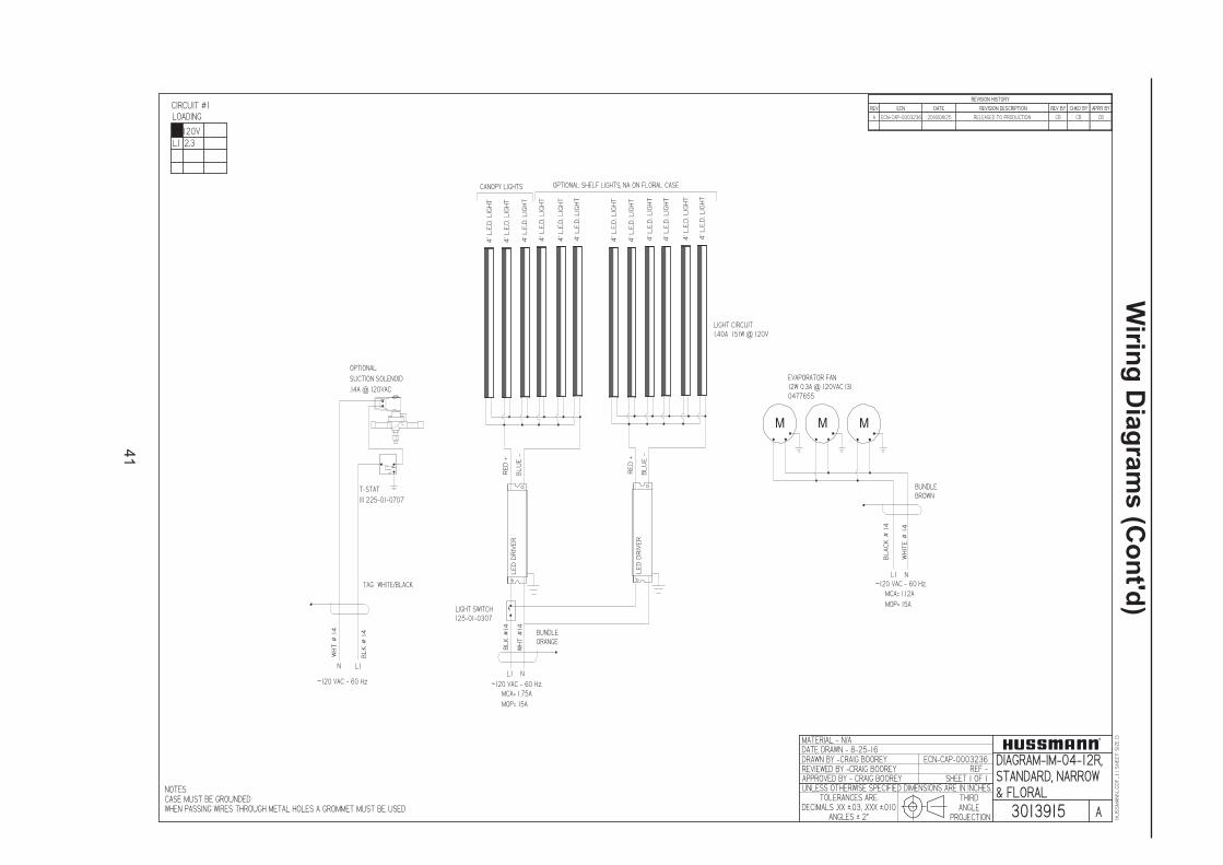
41
Wirin
g D
iag
ram
s (C
on
t'd)
HUSSMANN_GDF_1.1SHEETSIZEDMATERIAL - N/A
THIRDANGLE
PROJECTION
UNLESS OTHERWISE SPECIFIED DIMENSIONS ARE IN INCHES.
DRAWN BY -CRAIG BOOREY
APPROVED BY - CRAIG BOOREY
TOLERANCES ARE:DECIMALS .XX u.03, .XXX u.010
ANGLES u 2v
DATE DRAWN - 8-25-16ECN-CAP-0003236
REVIEWED BY -CRAIG BOOREY REF -
3013915
DIAGRAM-IM-04-12R,STANDARD, NARROW& FLORAL
REV ECN DATE REVISION DESCRIPTION REV BY CHKD BY APPR BY
A ECN-CAP-0003236 2016/08/25 RELEASED TO PRODUCTION CB CB CB
REVISION HISTORY
NOTES:CASE MUST BE GROUNDEDWHEN PASSING WIRES THROUGH METAL HOLES A GROMMET MUST BE USED A
SHEET 1 OF 1
CIRCUIT #1
L1
LOADING
2.3120V
BUNDLEBROWN
M M
BLACK#14
WHITE#14
~120 VAC - 60 Hz.L1 N
MCA= 1.12AMOP= 15A
M
EVAPORATOR FAN12W 0.3A @ 120VAC (3)0477655
~120 VAC - 60 Hz.
CANOPY LIGHTS
LEDDRIVER
BUNDLEORANGE
MCA= 1.75AMOP= 15A
L1 N
RED+
BLUE-
OPTIONAL SHELF LIGHTS, NA ON FLORAL CASE
LEDDRIVER
RED+
BLUE-
LIGHT SWITCH125-01-0307
BLK#14
WHT#14
4'L.E.D.LIGHT
LIGHT CIRCUIT1.40A 151W @ 120V
4'L.E.D.LIGHT
4'L.E.D.LIGHT
4'L.E.D.LIGHT
4'L.E.D.LIGHT
4'L.E.D.LIGHT
4'L.E.D.LIGHT
4'L.E.D.LIGHT
4'L.E.D.LIGHT
4'L.E.D.LIGHT
4'L.E.D.LIGHT
4'L.E.D.LIGHT
T-STAT(1) 225-01-0707
TAG WHITE/BLACK
~120 VAC - 60 Hz
BLK#14
L1N
WHT#14
OPTIONAL:SUCTION SOLENOID.14A @ 120VAC

42
Wirin
g D
iag
ram
s (C
on
t'd)
HUSSMANN_GDF_1.1SHEETSIZEDMATERIAL - N/A
THIRDANGLE
PROJECTION
UNLESS OTHERWISE SPECIFIED DIMENSIONS ARE IN INCHES.
DRAWN BY -CRAIG BOOREY
APPROVED BY - CRAIG BOOREY
TOLERANCES ARE:DECIMALS .XX u.03, .XXX u.010
ANGLES u 2v
DATE DRAWN - 8-26-16ECN-CAP-0003237
REVIEWED BY -CRAIG BOOREY REF -
3014000
DIAGRAM-IM-05-3R,STANDARD, NARROW& FLORAL
REV ECN DATE REVISION DESCRIPTION REV BY CHKD BY APPR BY
A ECN-CAP-0003237 2016/08/26 RELEASED TO PRODUCTION CB CB CB
REVISION HISTORY
NOTES:CASE MUST BE GROUNDEDWHEN PASSING WIRES THROUGH METAL HOLES A GROMMET MUST BE USED A
SHEET 1 OF 1
CIRCUIT #1
L1
LOADING
0.7120V
BUNDLEBROWN
BLACK#14
WHITE#14
~120 VAC - 60 Hz.L1 N
MCA= 0.38AMOP= 15A
M
EVAPORATOR FAN12W 0.3A @ 120VAC0477655
T-STAT(1) 225-01-0707
TAG WHITE/BLACK
~120 VAC - 60 Hz
BLK#14
L1N
WHT#14
OPTIONAL:SUCTION SOLENOID.14A @ 120VAC
~120 VAC - 60 Hz.
CANOPYLIGHTS
LEDDRIVER
BUNDLEORANGE
MCA= 0.51AMOP= 15A
L1 N
RED+
BLUE-
OPTIONAL: SHELF LIGHTSNA ON FLORAL CASE
LIGHT SWITCH125-01-0307
BLK#14
WHT#14
LIGHT CIRCUIT0.41A 44W @ 120V
3L.E.D.LIGHT
3L.E.D.LIGHT
3L.E.D.LIGHT
3L.E.D.LIGHT
3L.E.D.LIGHT
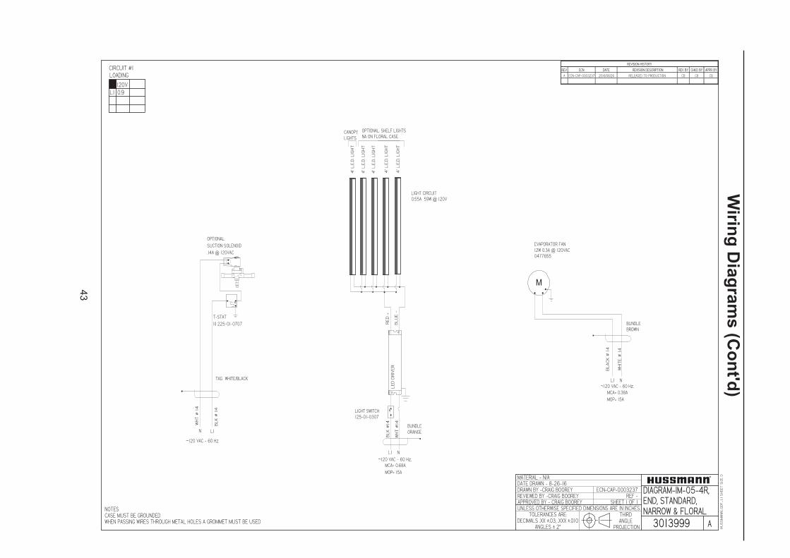
43
Wirin
g D
iag
ram
s (C
on
t'd)
HUSSMANN_GDF_1.1SHEETSIZEDMATERIAL - N/A
THIRDANGLE
PROJECTION
UNLESS OTHERWISE SPECIFIED DIMENSIONS ARE IN INCHES.
DRAWN BY -CRAIG BOOREY
APPROVED BY - CRAIG BOOREY
TOLERANCES ARE:DECIMALS .XX u.03, .XXX u.010
ANGLES u 2v
DATE DRAWN - 8-26-16ECN-CAP-0003237
REVIEWED BY -CRAIG BOOREY REF -
3013999
DIAGRAM-IM-05-4R,END, STANDARD,NARROW & FLORAL
REV ECN DATE REVISION DESCRIPTION REV BY CHKD BY APPR BY
A ECN-CAP-0003237 2016/08/26 RELEASED TO PRODUCTION CB CB CB
REVISION HISTORY
NOTES:CASE MUST BE GROUNDEDWHEN PASSING WIRES THROUGH METAL HOLES A GROMMET MUST BE USED A
SHEET 1 OF 1
CIRCUIT #1
L1
LOADING
0.9120V
BUNDLEBROWN
BLACK#14
WHITE#14
~120 VAC - 60 Hz.L1 N
MCA= 0.38AMOP= 15A
M
EVAPORATOR FAN12W 0.3A @ 120VAC0477655
T-STAT(1) 225-01-0707
TAG WHITE/BLACK
~120 VAC - 60 Hz
BLK#14
L1N
WHT#14
OPTIONAL:SUCTION SOLENOID.14A @ 120VAC
~120 VAC - 60 Hz.
CANOPYLIGHTS
LEDDRIVER
BUNDLEORANGE
MCA= 0.68AMOP= 15A
L1 N
RED+
BLUE-
OPTIONAL: SHELF LIGHTSNA ON FLORAL CASE
LIGHT SWITCH125-01-0307
BLK#14
WHT#14
LIGHT CIRCUIT0.55A 59W @ 120V
4'L.E.D.LIGHT
4'L.E.D.LIGHT
4'L.E.D.LIGHT
4'L.E.D.LIGHT
4'L.E.D.LIGHT

44
Wirin
g D
iag
ram
s (C
on
t'd)
DATE:
PROJECT TITLE: DRAWING #:DRAWN BY:
PRODUCTION ORDER #: DRAWING TITLE:
DATE:Hussmann Corporation, Int'l.
13770 Ramona Avenue
Chino, CA. 91710
(909)-590-4910 Lic.#: 644406
REVISIONS:
#: DESCRIPTION: CHECKED BY:BY:
FILE LOCATION:
JESSE RIOS
PAGE OF1 1
501398
1 1
2/25/09ISLA CASES 1H19654
IM-04-C4-R, IM-04-I5-R, IM-04-E5-R W/T-5 LIGHTS
BUNDLEORANGE
BUNDLEBROWN
F3
5T
5-6
0"
12
5-0
3- 1
13
4
M
LIGHT CIRCUIT= 1.3A 140W
EVAPORATOR FAN12W 0.3A @ 120VAC0477655
F3
5T
5-6
0"
12
5-0
3-1
13
4
F3
5T
5- 6
0"
12
5-0
3- 1
13
4
F3
5T
5-6
0"
12
5-0
3-1
13
4
BA
LL
AS
T1
H5
73
00
55
0
FU
LH
AM
LH
5-1
20
-L
BA
LL
AS
T1
H5
73
00
55
0
FU
LH
AM
LH
5-1
20
-L
BL
AC
K#
14
WH
ITE
#1
4
~120 VAC - 60 Hz.
L1 N
MCA= .37A
MOP= 15A
BL
AC
K#
14
WH
I TE
#1
4
~120 VAC - 60 Hz.L1 N
MCA= 1.63A
MOP= 15A
LIGHT SWITCH125-01-0307
CIRCUIT #1
NOTE: CASE MUSTBE GROUNDED
1L 6.1
120 V
LOADING
C Made changes to reflect latest production models 5/7/10 JRD Changed Ballast to Longhorse 5 8/5/11 CBE Changed Fan Motor 11/18/11 CB
®

45
Wirin
g D
iag
ram
s (C
on
t'd)
DATE:
PROJECT TITLE: DRAWING #:DRAWN BY:
PRODUCTION ORDER #: DRAWING TITLE:
DATE:Hussmann Corporation, Int'l.
13770 Ramona Avenue
Chino, CA. 91710
(909)-590-4910 Lic.#: 644406
REVISIONS:
#: DESCRIPTION: CHECKED BY:BY:
FILE LOCATION:
JESSE RIOS
PAGE OF1 1
501398
1 1
2/25/09ISLA CASES 1H19654
IM-04-C4-R, IM-04-I5-R, IM-04-E5-R W/T-5 LIGHTS
BUNDLEORANGE
BUNDLEBROWN
F3
5T
5-6
0"
12
5-0
3- 1
13
4
M
LIGHT CIRCUIT= 1.3A 140W
EVAPORATOR FAN12W 0.3A @ 120VAC0477655
F3
5T
5-6
0"
12
5-0
3-1
13
4
F3
5T
5- 6
0"
12
5-0
3- 1
13
4
F3
5T
5-6
0"
12
5-0
3-1
13
4
BA
LL
AS
T1
H5
73
00
55
0
FU
LH
AM
LH
5-1
20
-L
BA
LL
AS
T1
H5
73
00
55
0
FU
LH
AM
LH
5-1
20
-L
BL
AC
K#
14
WH
ITE
#1
4
~120 VAC - 60 Hz.
L1 N
MCA= .37A
MOP= 15A
BL
AC
K#
14
WH
I TE
#1
4
~120 VAC - 60 Hz.L1 N
MCA= 1.63A
MOP= 15A
LIGHT SWITCH125-01-0307
CIRCUIT #1
NOTE: CASE MUSTBE GROUNDED
1L 6.1
120 V
LOADING
C Made changes to reflect latest production models 5/7/10 JRD Changed Ballast to Longhorse 5 8/5/11 CBE Changed Fan Motor 11/18/11 CB
®

46
Wirin
g D
iag
ram
s (C
on
t'd)
HUSSMANN_GDF_1.1SHEETSIZEDMATERIAL - N/A
THIRDANGLE
PROJECTION
UNLESS OTHERWISE SPECIFIED DIMENSIONS ARE IN INCHES.
DRAWN BY -CRAIG BOOREY
APPROVED BY - CRAIG BOOREY
TOLERANCES ARE:DECIMALS .XX u.03, .XXX u.010
ANGLES u 2v
DATE DRAWN - 8-26-16ECN-CAP-0003237
REVIEWED BY -CRAIG BOOREY REF -
3013998
DIAGRAM-IM-05-5R,END, STANDARD,NARROW & FLORAL
REV ECN DATE REVISION DESCRIPTION REV BY CHKD BY APPR BY
A ECN-CAP-0003237 2016/08/26 RELEASED TO PRODUCTION CB CB CB
REVISION HISTORY
NOTES:CASE MUST BE GROUNDEDWHEN PASSING WIRES THROUGH METAL HOLES A GROMMET MUST BE USED A
SHEET 1 OF 1
CIRCUIT #1
L1
LOADING
1.0120V
BUNDLEBROWN
BLACK#14
WHITE#14
~120 VAC - 60 Hz.L1 N
MCA= 0.38AMOP= 15A
M
EVAPORATOR FAN12W 0.3A @ 120VAC0477655
T-STAT(1) 225-01-0707
TAG WHITE/BLACK
~120 VAC - 60 Hz
BLK#14
L1N
WHT#14
OPTIONAL:SUCTION SOLENOID.14A @ 120VAC
~120 VAC - 60 Hz.
CANOPYLIGHTS
LEDDRIVER
BUNDLEORANGE
MCA= 0.87AMOP= 15A
L1 N
RED+
BLUE-
OPTIONAL: SHELF LIGHTSNA ON FLORAL CASE
LIGHT SWITCH125-01-0307
BLK#14
WHT#14
LIGHT CIRCUIT0.70A 75W @ 120V
5'L.E.D.LIGHT
5'L.E.D.LIGHT
5'L.E.D.LIGHT
5'L.E.D.LIGHT
5'L.E.D.LIGHT

47
Wirin
g D
iag
ram
s (C
on
t'd)
HUSSMANN_GDF_1.1SHEETSIZEDMATERIAL - N/A
THIRDANGLE
PROJECTION
UNLESS OTHERWISE SPECIFIED DIMENSIONS ARE IN INCHES.
DRAWN BY -CRAIG BOOREY
APPROVED BY - CRAIG BOOREY
TOLERANCES ARE:DECIMALS .XX u.03, .XXX u.010
ANGLES u 2v
DATE DRAWN - 8-26-16ECN-CAP-0003237
REVIEWED BY -CRAIG BOOREY REF -
3013997
DIAGRAM-IM-05-6R,STANDARD, NARROW& FLORAL
REV ECN DATE REVISION DESCRIPTION REV BY CHKD BY APPR BY
A ECN-CAP-0003237 2016/08/26 RELEASED TO PRODUCTION CB CB CB
REVISION HISTORY
NOTES:CASE MUST BE GROUNDEDWHEN PASSING WIRES THROUGH METAL HOLES A GROMMET MUST BE USED A
SHEET 1 OF 1
CIRCUIT #1
L1
LOADING
1.4120V
BUNDLEBROWN
M
BLACK#14
WHITE#14
~120 VAC - 60 Hz.L1 N
MCA= 0.75AMOP= 15A
M
EVAPORATOR FAN12W 0.3A @ 120VAC(2) 0477655
T-STAT(1) 225-01-0707
TAG WHITE/BLACK
~120 VAC - 60 Hz
BLK#14
L1N
WHT#14
OPTIONAL:SUCTION SOLENOID.14A @ 120VAC
~120 VAC - 60 Hz.
CANOPY LIGHTS
LEDDRIVER
BUNDLEORANGE
MCA= 1.02AMOP= 15A
L1 N
RED+
BLUE-
OPTIONAL: SHELF LIGHTS, NA ON FLORAL CASE
LEDDRIVER
RED+
BLUE-
LIGHT SWITCH125-01-0307
BLK#14
WHT#14
LIGHT CIRCUIT0.82A 88W @ 120V
3'L.E.D.LIGHT
3'L.E.D.LIGHT
3'L.E.D.LIGHT
3'L.E.D.LIGHT
3'L.E.D.LIGHT
3'L.E.D.LIGHT
3'L.E.D.LIGHT
3'L.E.D.LIGHT
3'L.E.D.LIGHT
3'L.E.D.LIGHT
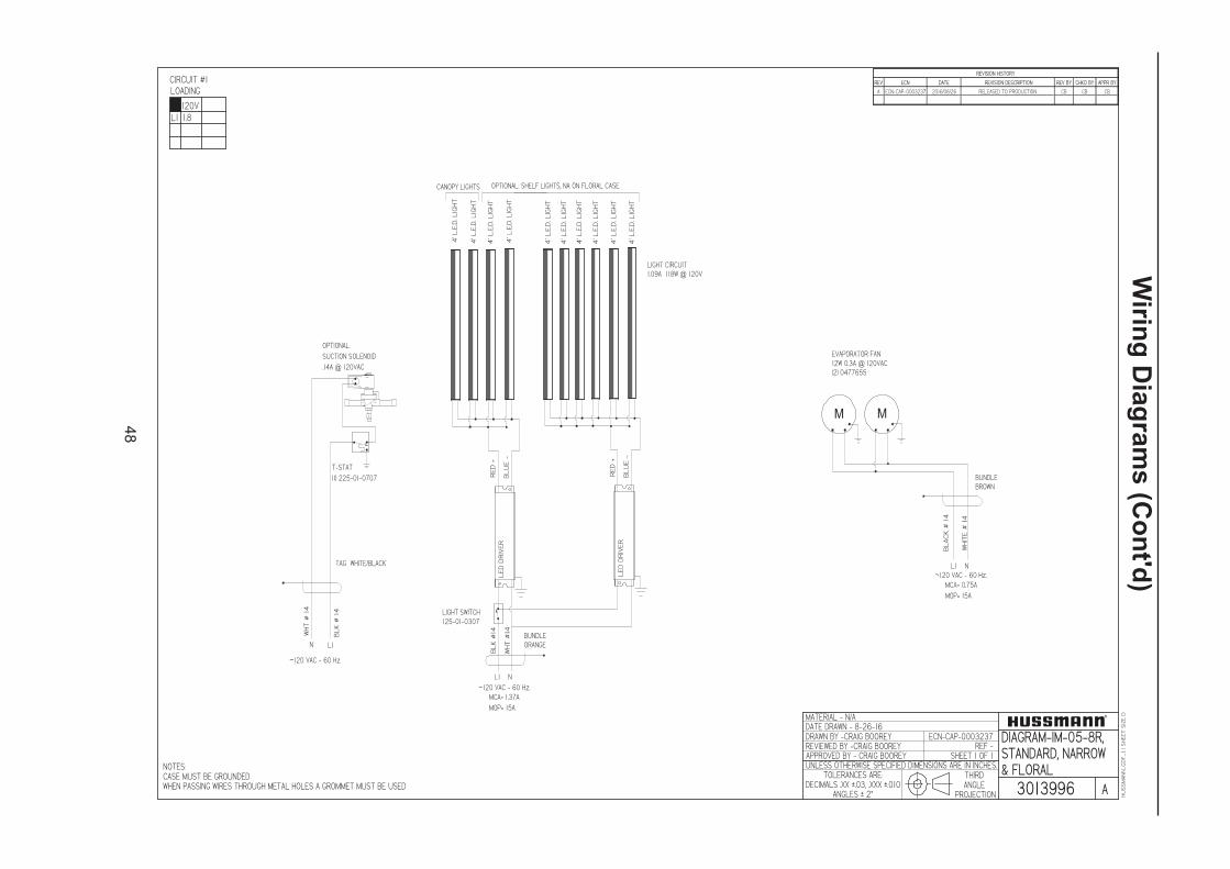
48
Wirin
g D
iag
ram
s (C
on
t'd)
HUSSMANN_GDF_1.1SHEETSIZEDMATERIAL - N/A
THIRDANGLE
PROJECTION
UNLESS OTHERWISE SPECIFIED DIMENSIONS ARE IN INCHES.
DRAWN BY -CRAIG BOOREY
APPROVED BY - CRAIG BOOREY
TOLERANCES ARE:DECIMALS .XX u.03, .XXX u.010
ANGLES u 2v
DATE DRAWN - 8-26-16ECN-CAP-0003237
REVIEWED BY -CRAIG BOOREY REF -
3013996
DIAGRAM-IM-05-8R,STANDARD, NARROW& FLORAL
REV ECN DATE REVISION DESCRIPTION REV BY CHKD BY APPR BY
A ECN-CAP-0003237 2016/08/26 RELEASED TO PRODUCTION CB CB CB
REVISION HISTORY
NOTES:CASE MUST BE GROUNDEDWHEN PASSING WIRES THROUGH METAL HOLES A GROMMET MUST BE USED A
SHEET 1 OF 1
CIRCUIT #1
L1
LOADING
1.8120V
BUNDLEBROWN
M
BLACK#14
WHITE#14
~120 VAC - 60 Hz.L1 N
MCA= 0.75AMOP= 15A
M
EVAPORATOR FAN12W 0.3A @ 120VAC(2) 0477655
T-STAT(1) 225-01-0707
TAG WHITE/BLACK
~120 VAC - 60 Hz
BLK#14
L1N
WHT#14
OPTIONAL:SUCTION SOLENOID.14A @ 120VAC
~120 VAC - 60 Hz.
CANOPY LIGHTS
LEDDRIVER
BUNDLEORANGE
MCA= 1.37AMOP= 15A
L1 N
4'L.E.D.LIGHT
RED+
BLUE-
OPTIONAL: SHELF LIGHTS, NA ON FLORAL CASE
LEDDRIVER
RED+
BLUE-
LIGHT SWITCH125-01-0307
BLK#14
WHT#14
LIGHT CIRCUIT1.09A 118W @ 120V
4'L.E.D.LIGHT
4'L.E.D.LIGHT
4'L.E.D.LIGHT
4'L.E.D.LIGHT
4'L.E.D.LIGHT
4'L.E.D.LIGHT
4'L.E.D.LIGHT
4'L.E.D.LIGHT
4'L.E.D.LIGHT

49
Wirin
g D
iag
ram
s (C
on
t'd)
HUSSMANN_GDF_1.1SHEETSIZEDMATERIAL - N/A
THIRDANGLE
PROJECTION
UNLESS OTHERWISE SPECIFIED DIMENSIONS ARE IN INCHES.
DRAWN BY -CRAIG BOOREY
APPROVED BY - CRAIG BOOREY
TOLERANCES ARE:DECIMALS .XX u.03, .XXX u.010
ANGLES u 2v
DATE DRAWN - 8-26-16ECN-CAP-0003237
REVIEWED BY -CRAIG BOOREY REF -
3013995
DIAGRAM-IM-05-10R,STANDARD, NARROW& FLORAL
REV ECN DATE REVISION DESCRIPTION REV BY CHKD BY APPR BY
A ECN-CAP-0003237 2016/08/26 RELEASED TO PRODUCTION CB CB CB
REVISION HISTORY
NOTES:CASE MUST BE GROUNDEDWHEN PASSING WIRES THROUGH METAL HOLES A GROMMET MUST BE USED A
SHEET 1 OF 1
CIRCUIT #1
L1
LOADING
2.0120V
BUNDLEBROWN
M
BLACK#14
WHITE#14
~120 VAC - 60 Hz.L1 N
MCA= 0.75AMOP= 15A
M
EVAPORATOR FAN12W 0.3A @ 120VAC(2) 0477655
T-STAT(1) 225-01-0707
TAG WHITE/BLACK
~120 VAC - 60 Hz
BLK#14
L1N
WHT#14
OPTIONAL:SUCTION SOLENOID.14A @ 120VAC
~120 VAC - 60 Hz.
CANOPY LIGHTS
LEDDRIVER
BUNDLEORANGE
MCA= 1.74AMOP= 15A
L1 N
5'L.E.D.LIGHT
RED+
BLUE-
OPTIONAL: SHELF LIGHTS, NA ON FLORAL CASE
LEDDRIVER
RED+
BLUE-
LIGHT SWITCH125-01-0307
BLK#14
WHT#14
LEDDRIVER
RED+
BLUE-
5'L.E.D.LIGHT
LIGHT CIRCUIT1.39A 150W @ 120V
5'L.E.D.LIGHT
5'L.E.D.LIGHT
5'L.E.D.LIGHT
5'L.E.D.LIGHT
5'L.E.D.LIGHT
5'L.E.D.LIGHT
5'L.E.D.LIGHT
5'L.E.D.LIGHT

50
Wirin
g D
iag
ram
s (C
on
t'd)
HUSSMANN_GDF_1.1SHEETSIZEDMATERIAL - N/A
THIRDANGLE
PROJECTION
UNLESS OTHERWISE SPECIFIED DIMENSIONS ARE IN INCHES.
DRAWN BY -CRAIG BOOREY
APPROVED BY - CRAIG BOOREY
TOLERANCES ARE:DECIMALS .XX u.03, .XXX u.010
ANGLES u 2v
DATE DRAWN - 8-26-16ECN-CAP-0003237
REVIEWED BY -CRAIG BOOREY REF -
3013994
DIAGRAM-IM-05-12R,STANDARD, NARROW& FLORAL
REV ECN DATE REVISION DESCRIPTION REV BY CHKD BY APPR BY
A ECN-CAP-0003237 2016/08/26 RELEASED TO PRODUCTION CB CB CB
REVISION HISTORY
NOTES:CASE MUST BE GROUNDEDWHEN PASSING WIRES THROUGH METAL HOLES A GROMMET MUST BE USED A
SHEET 1 OF 1
CIRCUIT #1
L1
LOADING
2.6120V
BUNDLEBROWN
M M
BLACK#14
WHITE#14
~120 VAC - 60 Hz.L1 N
MCA= 1.12AMOP= 15A
M
EVAPORATOR FAN12W 0.3A @ 120VAC(3) 0477655
T-STAT(1) 225-01-0707
TAG WHITE/BLACK
~120 VAC - 60 Hz
BLK#14
L1N
WHT#14
OPTIONAL:SUCTION SOLENOID.14A @ 120VAC
~120 VAC - 60 Hz.
CANOPY LIGHTS
LEDDRIVER
BUNDLEORANGE
MCA= 2.1AMOP= 15A
L1 N
4'L.E.D.LIGHT
RED+
BLUE-
OPTIONAL: SHELF LIGHTS, NA ON FLORAL CASE
LEDDRIVER
RED+
BLUE-
LIGHT SWITCH125-01-0307
BLK#14
WHT#14
LEDDRIVER
RED+
BLUE-
4'L.E.D.LIGHT
4'L.E.D.LIGHT
4'L.E.D.LIGHT
4'L.E.D.LIGHT
4'L.E.D.LIGHT
4'L.E.D.LIGHT
4'L.E.D.LIGHT
4'L.E.D.LIGHT
4'L.E.D.LIGHT
4'L.E.D.LIGHT
4'L.E.D.LIGHT
4'L.E.D.LIGHT
4'L.E.D.LIGHT
4'L.E.D.LIGHT
LIGHT CIRCUIT1.64A 177W @ 120V

51
Wirin
g D
iag
ram
s (C
on
t'd)
�������
����
�� ��������
����
�����������
����������
����������������������������������������������������������������
�������������������������� ������������
�������� ������
������� �
��� � ������������������������
�������������������
�������� ��!�������"�!�����" ���
��������� ��#! �! �
��� $%&�%$�� ��!�
����'���" ��������(���" ���
��(������������"��( ��� ��� ��(���������������� ��(��" ��'��" ������"� ��)$%&�%$ �#! �! � �* �+,*-�./*��*012�3455*3.+45 �� �� ��� ��)$$&$�# � !��! � �* �+,*-��*012 �� �� �� ���)#$#6�% ��! �! 6 �/157*-��819��15���*8+:*-��41-: �� �� ��
� ��� ��� ���%&;$
�! �! $ ������������ ��� ��� ���
�����������
������������ �6 � ���&
��
����'�)� �
������)� �
M
�(����������� ���������<� ��(���%&&$66
���������������������=�% ��6$ �� �% �%�%� ��; 6�6��
�����������������>� ��6������������>6%�6����������>� %�;��
�
�����"�����
����������6 6�
�����������
����� �6 � ��#$
�������?�����@@�66%%& �6 � ��&
����" �"���#��&��� ���%6#��%��
�
�
� �
��
�����A��(�����"A� 6�� � �����;����<�B� ���(�� �#6 �%66�
� �
� �
���������
����������
SAFE NET III CONTROLERPART# 1H59048001
SAFE NET III SENSORSPART# 0510533 (4m long) black pb1 AIRPART# 0510532 (4m long) Yellow pb2 COIL
������������������' �6 � ��#6
����(�� �����"
��(����
6 ;
;#;
���� ��$����
��������������������$��<� ��(
���C
�����
�6��' �
D��������
����
%%% 6
;&
�6��' �
D��������
����
%%% 6
;&
�6��' �
D��������
����
%%% 6
;&
�6��' �
D��������
����
%%% 6
;&
����"������
�����������
�������)
������������������������
#�%� ���(������

52
Wirin
g D
iag
ram
s (C
on
t'd)
DATE:
PROJECT TITLE: DRAWING #:DRAWN BY:
PRODUCTION ORDER #: DRAWING TITLE:
DATE:Hussmann Corporation, Int'l.
13770 Ramona Avenue
Chino, CA. 91710
(909)-590-4910 Lic.#: 644406
REVISIONS:
#: DESCRIPTION: CHECKED BY:BY:
FILE LOCATION:
CRAIG BOOREY
PAGE OF
11 1
11/21/11
B CN#647046, Re-Wired the Relay connection 9/10/12 SPC CN#987576 Changed Evaporator Pan 6/19/15 CBD ECN-CAP-0004786 SYNC REVISION WITH TC 10/13/16 NCL
ISLA CASES 1H66352
DIAGRAM-IM-04-I4-S W/LED LIGHTS
BUNDLEORANGE
M
EVAPORATOR FAN12W 0.30A @ 120VAC0477655
LIGHT SWITCH125-01-0307
CONDENSING UNITCOPELAND®M4FF-0075-CAV-212R404A1H21855
CONDENSING UNITRLA= 6.8 ALRA= 33.7AMCC= 9.7AL2
L1
G
SWITCH
SQUARE "D" 55447
125-01-0271
RELAY TYCO
T92P7A22-277
1804241L2
L1
L1 L2
EVAPORATOR PAN1500W 6.25A @ ~ 240 VAC1H95137550
L2L1
NL1 N
L1
BUNDLEBROWN
SAFE NET III CONTROLERPART# 1H59048001
SAFE NET III SENSORSPART# 0510533 (4m long) black pb1 AIRPART# 0510532 (4m long) Yellow pb2 COIL
M
15
A
15 AMP FUSE125-01-8604FUSE HOLDER125-01-8605
L2
Black 10 G.
Red 10 G.
White 14 G.
Green 10 G.
CANOPY
35
00
K-4
' L.E
.D. L
IGH
T4
44
15
91
RE
D +
BL
UE
-
LIGHT CIRCUIT (INPUT)48W 0.44A @ 120VAC
PROGRAM: 1H59684
LE
D D
RIV
ER
SHELVES
35
00
K-4
' L.E
.D. L
IGH
T4
44
15
91
35
00
K-4
' L.E
.D. L
IGH
T4
44
15
91
35
00
K-4
' L.E
.D. L
IGH
T4
44
15
91
G
L2
L1
N
TERMINAL BLOCK125-01-0295
CIRCUIT #1
SAFETYSWITCH
FLOAT SWITCH
CIRCUIT #1
NOTE: CASE MUSTBE GROUNDED
13.813.1
12.011.4
L1
L2
208 V 240V
LOADING

53
Wirin
g D
iag
ram
s (C
on
t'd)
�������
����
�� ��������
����
�����������
����������
����������������������������������������������������������������
�������������������������� ������������
�������� ������
������� �
��� � ������������������
����������� ������!"� ����!"���!
������������# � �
����$%&�%$����� �
����'��!"���!�����(��!"���!
��(������������"��( ��� ��� ��(���������������� ��(�!" ��'�!" �����!"
! $%&�%$ �# � � �)��*+),�-.)��)/01�2344)2-*34 �� �� ��� &5 %�� �� �6 % �.047),��8093+0-3+��04 �! �! �! ##$%&% �5 �6 6 �.047),��3:9+);;3+ �! �! �!� �����������%&5$ � � $ ������������ ��� ��� ���
!����������
������������ �6�� ����&
��
��<
� %
!�
'�<
� %
����(�� �����"
��
��
�(�
�
��������������6$���$���=� ��(�
�
�>
!�
��
��
�6
��
'�6
?����
����
���
�%
%%
$5
�
6�
�'
�6?��
���
�����
��
%%
% $
5
�6
��
'�6
?����
����
���
�%
%%
$5
�
6�
�'
�6?��
���
�����
��
%%
% $
5
M
�(����������� ���������=� ��(���%&&$66
� �
!����!����
���������������������@���� �5��(�����%�%��� �$�$
�����������������A�#������A�%$�������������A ��5�
��
�
�
�������B�����CC�66%%& �6�� ���&
����" �"���#��&�����&& 5�%�%
���
� ��
�(������������ 6����$��6��=�D��%��(�� �#6 �&66�
���
�
�
SAFE NET III CONTROLERPART# 1H59048001
SAFE NET III SENSORSPART# 0510533 (4m long) black pb1 AIRPART# 0510532 (4m long) Yellow pb2 COIL
�
��
�
��
!/02E� ���
�),� ����
�.*-)� %���
�+))4� ����
PROGRAM: 1H59684
TERMINALBLOCK125-01-0295
����"������
�����������
��������<
�����
����������!��������
%�� ��$
� ��5�(���%�(������
$�% 6�$

54
Wirin
g D
iag
ram
s (C
on
t'd)
HUSSMANN_GDF_1.1SHEETSIZEDMATERIAL - N/A
THIRDANGLE
PROJECTION
UNLESS OTHERWISE SPECIFIED DIMENSIONS ARE IN INCHES.
DRAWN BY -CRAIG BOOREY
APPROVED BY - CRAIG BOOREY
TOLERANCES ARE:DECIMALS .XX u.03, .XXX u.010
ANGLES u 2v
DATE DRAWN - 4-18-16ECN-CAP-0001113
REVIEWED BY -CRAIG BOOREY REF -
3004408
DIAGRAM-IM-04-I6-SAK-CC-210 CTLR
REV ECN DATE REVISION DESCRIPTION REV BY CHKD BY APPR BY
A ECN-CAP-0001113 2016/04/18 RELEASED TO PRODUCTION CB CB CB
REVISION HISTORY
NOTES:CASE MUST BE GROUNDEDWHEN PASSING WIRES THROUGH METAL HOLES A GROMMET MUST BE USED A
SHEET 1 OF 1
CIRCUIT #1
L1L2
LOADING
15.214.1
17.516.3
208V 240V
BUNDLEORANGE
M
EVAPORATOR FAN12W 0.30A @ 120VAC (2)0477655
LIGHT SWITCH125-01-0307
CONDENSING UNITCOPELAND®FJAF-B100-CFV-021R404A1H28147
CONDENSING UNITRLA= 10.0 ALRA= 51.0AMCC= 13.7A
G
EVAPORATOR PAN1500W 6.25A @ ~ 240 VAC1H95137550
L1
L1 N
L1
BUNDLEBROWN
M
MM
N
L2
G
L2
Black 10G.
Red 10 G.
White 14 G.Green 10 G.
BLK#14
WHT#14
TERMINAL BLOCK125-01-0295
SHELVES CANOPY
LEDDRIVER
RED+
BLUE-
3500K-3'L.E.D.LIGHT
4441587
3500K-3'L.E.D.LIGHT
4441587
3500K-3'L.E.D.LIGHT
4441587
3500K-3'L.E.D.LIGHT
4441587
3500K-3'L.E.D.LIGHT
4441587
3500K-3'L.E.D.LIGHT
4441587
3500K-3'L.E.D.LIGHT
4441587
3500K-3'L.E.D.LIGHT
4441587
LIGHT CIRCUIT.66A 72W @ 120V
SAFETYSWITCH
FLOAT SWITCH
BLACK#14
RED#14
BUNDLEBLUE
POWER SWITCH125-01-0271
L2
L1
RELAY TYCOT92P722A-2771804241
L1 L2
PRESSURESAFETY
MCONDENSERFAN
L1
DANFOSS® CONTROLLERAK-CC-210 115V # 084B85341H56892500
Danfoss® AK-CC 210
DEF.COMP.
120 VAC
SENSORDANFOSS®# 1H90012500
NOTE: WIRES ATCONTROLINPUTS/OUTPUTS14GA MAX
N
L2
L1
WHITE#14
L2
L1
15A
15 AMP FUSE125-01-8604FUSE HOLDER125-01-8605
Black 14G.
Red 14 G.
BLK#14
WHT#14

55
Wirin
g D
iag
ram
s (C
on
t'd)
HUSSMANN_GDF_1.1SHEETSIZEDMATERIAL - N/A
THIRDANGLE
PROJECTION
UNLESS OTHERWISE SPECIFIED DIMENSIONS ARE IN INCHES.
DRAWN BY -CRAIG BOOREY
APPROVED BY - CRAIG BOOREY
TOLERANCES ARE:DECIMALS .XX u.03, .XXX u.010
ANGLES u 2v
DATE DRAWN - 4-18-16ECN-CAP-0001113
REVIEWED BY -CRAIG BOOREY REF -
3004410
DIAGRAM-IM-04-I8-SAK-CC-210 CTLR
REV ECN DATE REVISION DESCRIPTION REV BY CHKD BY APPR BY
A ECN-CAP-0001113 2016/04/18 RELEASED TO PRODUCTION CB CB CB
REVISION HISTORY
NOTES:CASE MUST BE GROUNDEDWHEN PASSING WIRES THROUGH METAL HOLES A GROMMET MUST BE USED A
SHEET 1 OF 1
CIRCUIT #1
L1L2
LOADING
17.616.3
20.318.8
208V 240V
BUNDLEORANGE
M
EVAPORATOR FAN12W 0.30A @ 120VAC (2)0477655
LIGHT SWITCH125-01-0307
CONDENSING UNITCOPELAND®FFAP-017Z-CFV-072R404A1H96225500
CONDENSING UNITRLA= 12.6 ALRA= 55.0AMCC= 17.2A
G
EVAPORATOR PAN1500W 6.25A @ ~ 240 VAC1H95137550
N L1 N
L1
BUNDLEBROWN
M
MM
15A
15 AMP FUSE125-01-8604FUSE HOLDER125-01-8605 L2
Black 10 G.
Red 10 G.
White 14 G.Green 10 G.
LEDDRIVER
RED+
BLUE-
LEDDRIVER
RED+
BLUE-
CANOPY
3500K-4'L.E.D.LIGHT
4441591
SHELVES
3500K-4'L.E.D.LIGHT
4441591
3500K-4'L.E.D.LIGHT
4441591
3500K-4'L.E.D.LIGHT
4441591
3500K-4'L.E.D.LIGHT
4441591
3500K-4'L.E.D.LIGHT
4441591
3500K-4'L.E.D.LIGHT
4441591
3500K-4'L.E.D.LIGHT
4441591
LIGHT CIRCUIT.89A 96W @ 120V
~208 / ~240 VAC - 60 HZ
G
L2
L1
N
TERMINALBLOCK125-01-0295
GREEN # 10
SAFETYSWITCH
FLOAT SWITCH
BLACK#14
RED#14
BUNDLEBLUE
POWER SWITCH125-01-0271
L2
L1
RELAY TYCOT92P722A-2771804241
L1 L2
PRESSURESAFETY
MCONDENSERFAN
L1
DANFOSS® CONTROLLERAK-CC-210 115V # 084B85341H56892500
Danfoss® AK-CC 210
DEF.COMP.
120 VAC
SENSORDANFOSS®# 1H90012500
NOTE: WIRES ATCONTROLINPUTS/OUTPUTS14GA MAX
N
L2
L1
WHITE#14
L2
L1

56
Wirin
g D
iag
ram
s (C
on
t'd)
HUSSMANN_GDF_2.1SHEETSIZED
THIRDANGLE
PROJECTION
UNLESS OTHERWISE SPECIFIED DIMENSIONS ARE IN INCHES.TOLERANCES ARE:
DECIMALS .XX u.03, .XXX u.010ANGLES u 2v
SHEET 1 OF 1
1H66329 E
DIAGRAM-IM-04-I6-SW/LED LIGHTS
MATERIAL- N/AMODEL BY / DWG BY- SP
DATE DRAWN - 09/10/12
ECN-647046REF- N/A
CHECKED BY- SPAPPROVED BY- SP
REVISION HISTORYREV ECN DATE REVISION DESCRIPTION REV BY CHKD BY APPR BYB 647046 09/10/12 Re-Wired the Relay connection SP SP SPC 781433 03/05/14 Changed Evaporator Pan CB CB CBD 987576 06/19/15 Updated C.U. Nomenclature CB CB CBE ECN-CAP-0004786 10/13/16 NEW TEMPLATE NCL NCL NCL
BUNDLEORANGE
M
EVAPORATOR FAN12W 0.30A @ 120VAC (2)0477655
LIGHT SWITCH125-01-0307
CONDENSING UNITCOPELAND®FJAF-B100-CFV-021R404A1H28147
CONDENSING UNITRLA= 10.0 A LRA=51.0A MCC= 13.7A
L2
L1
G
SWITCHSQUARE "D" 55447125-01-0271
RELAY TYCOT92P7A22-2771804241
L2L1
L1 L2
EVAPORATOR PAN1500W 6.25A @ ~ 240 VAC1H95137550
L2L1
L1
L1 N
L1
BUNDLEBROWN
SAFE NET III CONTROLERPART# 1H59048001
SAFE NET III SENSORSPART# 0510533 (4m long) black pb1 AIRPART# 0510532 (4m long) Yellow pb2 COIL
M
MM
N
L2
G
L2
Black 10G.
Red 10 G.
White 14 G.Green 10 G.
PROGRAM: 1H59684
BLK#14
WHT#14
TERMINALBLOCK125-01-0295
SHELVES CANOPY
LEDDRIVER
RED+
BLUE-
3500K-3'L.E.D.LIGHT
4441587
3500K-3'L.E.D.LIGHT
4441587
3500K-3'L.E.D.LIGHT
4441587
3500K-3'L.E.D.LIGHT
4441587
3500K-3'L.E.D.LIGHT
4441587
3500K-3'L.E.D.LIGHT
4441587
3500K-3'L.E.D.LIGHT
4441587
3500K-3'L.E.D.LIGHT
4441587
LIGHT CIRCUIT.66A 72W @ 120V
SAFETYSWITCH
FLOAT SWITCHM
CONDENSERFAN
CIRCUIT #1
NOTE:CASE MUST BE GROUNDED
17.516.3
15.214.1
L1L2
208 V 240VLOADING

57
Wirin
g D
iag
ram
s (C
on
t'd)
DATE:
PROJECT TITLE: DRAWING #:DRAWN BY:
PRODUCTION ORDER #: DRAWING TITLE:
DATE:Hussmann Corporation, Int'l.
13770 Ramona Avenue
Chino, CA. 91710
(909)-590-4910 Lic.#: 644406
REVISIONS:
#: DESCRIPTION: CHECKED BY:BY:
FILE LOCATION:
CRAIG BOOREY
PAGE OF1
947194
1 1
2/28/12
D CN#987576, Changed Cond. Unit 6/19/15 CBE CN#996474, Changed Cond. Unit 8/25/15 CBF CN#1005239, Changed Cond. Unit back to Rev-D 10/22/15 CB
IM-04-I8-S 1H71439
DIAGRAM-IM-04-I8-S W/LEDS & 30AMP POWER CORD
BUNDLEORANGE
M
EVAPORATOR FAN12W 0.30A @ 120VAC(2) 0477655
LIGHT SWITCH125-01-0307
CONDENSING UNITCOPELAND®FFAP-017Z-CFV-072R404A1H96225500
CONDENSING UNITRLA= 12.6 ALRA= 55.0AMCC= 17.2AL2
L1
G
SWITCH
SQUARE "D" 55447
125-01-0271
RELAY TYCO
T92P7A22-240
01804241L2
L1
L1 L2
EVAPORATOR PAN1500W 6.25A @ ~ 240 VAC1H95137550
L2L1
NL1 N
L1
BUNDLEBROWN
SAFE NET III CONTROLERPART# 1H59048001
SAFE NET III SENSORSPART# 0510533 (4m long) black pb1
AIRPART# 0510532 (4m long) Yellow pb2
COIL
M
MM
15
A
15 AMP FUSE125-01-8604FUSE HOLDER125-01-8605
L2
Black 10 G.
Red 10 G.
White 14 G.
Green 10 G.
PROGRAM: 1H59684
LE
DD
RIV
ER
RE
D+
BL
UE
-
LE
DD
RIV
ER
RE
D+
BL
UE
-
CANOPY
35
00
K-4
'L.E
.D.L
IGH
T4
44
15
91
SHELVES
35
00
K-4
'L.E
.D.L
IGH
T4
44
15
91
35
00
K-4
'L.E
.D.L
IGH
T4
44
15
91
35
00
K-4
'L.E
.D.L
IGH
T4
44
15
91
35
00
K-4
'L.E
.D.L
IGH
T4
44
15
91
35
00
K-4
'L.E
.D.L
IGH
T4
44
15
91
35
00
K-4
'L.E
.D.L
IGH
T4
44
15
91
35
00
K-4
'L.E
.D.L
IGH
T4
44
15
91
LIGHT CIRCUIT.89A 96W @ 120V
~208 / ~240 VAC - 60 HZ
G
L2
L1
N
POWERCORDPLUGNEMAL14-30P4 WIRESGROUNDED125-01-8503
GREEN # 10
SAFETYSWITCH
FLOAT SWITCH
CIRCUIT #1
NOTE: CASE MUSTBE GROUNDED
20.3
18.8
17.6
16.3
L1
L2
208 V 240V
LOADING

58
Wirin
g D
iag
ram
s (C
on
t'd)
DATE:
PROJECT TITLE: DRAWING #:DRAWN BY:
PRODUCTION ORDER #: DRAWING TITLE:
DATE:Hussmann Corporation, Int'l.
13770 Ramona Avenue
Chino, CA. 91710
(909)-590-4910 Lic.#: 644406
REVISIONS:
#: DESCRIPTION: CHECKED BY:BY:
FILE LOCATION:
CRAIG BOOREY
PAGE OF11 1
11/18/11
B CN#647046, Re-Wired the Relay connection 9/10/12 SPC CN#989596, Changed Evaporator Pan 6/19/15 CB
ISLA CASES 1H66327
DIAGRAM-IM-05-I3-S W/LED LIGHTS
BUNDLEORANGE
M
EVAPORATOR FAN12W 0.30A @ 120VAC0477655
L1 N
BUNDLEBROWN
CONDENSING UNITCOPELAND®M4FF-0075-CAV-212R404A1H28155
CONDENSING UNITRLA= 6.8A
LRA= 33.7.0AMCC= 9.7AL2
L1
G
SWITCH
SQUARE "D" 55447
125-01-0271
RELAY TYCO
T92P7A22-277
1804241L2L1
L1L2 EVAPORATOR PAN
1500W 6.25A @ ~ 240 VAC1H95137550
L2L1
L1
L1
SAFE NET III CONTROLERPART# 1H59048001
SAFE NET III SENSORSPART# 0510533 (4m long) black pb1
AIRPART# 0510532 (4m long) Yellow pb2
COIL
N
L2
G
L2
Black 10G.
Red 10 G.
White 14 G.
Green 10 G.
PROGRAM: 1H59684
TERMINAL BLOCK125-01-0295
LIGHT SWITCH125-01-0307
SHELVES CANOPY
LE
DD
RIV
ER
LIGHT CIRCUIT.42A 45W @ 120V
RE
D+
BL
UE
-
35
00
K-3
'L.E
.D.L
IGH
T4
44
15
87
35
00
K-3
'L.E
.D.L
IGH
T4
44
15
87
35
00
K-3
'L.E
.D.L
IGH
T4
44
15
87
35
00
K-3
'L.E
.D.L
IGH
T4
44
15
87
35
00
K-3
'L.E
.D.L
IGH
T4
44
15
87
SAFETYSWITCH
FLOAT SWITCH
PRESSURESAFETY
M
CONDENSERFAN
CIRCUIT #1
NOTE: CASE MUSTBE GROUNDED
12.0
11.4
L1
L2
208 V 240V
LOADING
13.8
13.1

59
Wirin
g D
iag
ram
s (C
on
t'd)
�������
����
�� ��������
����
�����������
����������
����������������������������������������������������������������
�������������������������� ������������
�������� ������
������� �
���� �� �� �� ������������
����������� ������!"� ����!"���!
������������# �
����$%&�%$����� �
����'��!"���!�����(��!"���!
��(������������"��( ��� ��� ��(���������������� ��(�!" ��'�!" �����!"
� �# � �)*+,-.��*/-+-0������1+02133-2�4�-+512��*20��678-25
�! �! �!
$%&�%$ �9 � � �-��:2-.�0)-��-3*;�<1++-<0:1+ �� �� ��� 9=9#9$ �$ 9 # �)*+,-.��>*?12*012��*+ �! �! �! �����������%&=$ � & $ ������������ ��� ��� ���
����������
!����������
M
�(����������� ���������@� ��(���%&&$##
������������ �#�� ����&
���������������������A���� �����(�����%�%� ��#%&$#��
�����������������B�9���������������B%�������������B� ��%�
��
�
�
�������C�����DD�##%%& �#�� ���&
����"���"���9��&�����%� =�%�%
���
� ��
�(������������ #����$��#��@�E��%��(�� �9# �&##�
���
� � �
�
!����!����
SAFE NET III CONTROLERPART# 1H59048001
SAFE NET III SENSORS(1) PART# 0510533 (4m long) BLACK pb1 AIR(1) PART# 0510532 (4M Long) YELLOW pb2 COIL
M
15
A
15 AMP FUSE125-01-8604FUSE HOLDER125-01-8605
��
!3*<F� ����
�-.� ����
�):0-� %����2--+� ����
�����"
�#
��
'�%
G����
����
���
�%
%%
#9
�
��
�H
!�
��
��
��������������I�����J�#����%��@� ��(��
PROGRAM: 1H59684
��
��
�(�
�
����(��
�#
��
'�%
G����
����
���
�%
%%
#9
��
#�
�'
�%G��
���
�����
��
%%
% #
9�
�#
��
'�%
G����
����
���
�%
%%
#9
��
#�
�'
�%G��
���
�����
��
%%
% #
9�
G
L2
L1
N
���������!���' �#�� ���9#
��������K
����"������
�����������
��������K
����������������!�������
$�� #��
��9 ���
� ��
��=�(�����%�(������
���������������!��������

60
Wirin
g D
iag
ram
s (C
on
t'd)
DATE:
PROJECT TITLE: DRAWING #:DRAWN BY:
PRODUCTION ORDER #: DRAWING TITLE:
DATE:Hussmann Corporation, Int'l.
13770 Ramona Avenue
Chino, CA. 91710
(909)-590-4910 Lic.#: 644406
REVISIONS:
#: DESCRIPTION: CHECKED BY:BY:
FILE LOCATION:
CRAIG BOOREY
PAGE OF
1 11 1
11/21/11
A CN#591361, New Release 11/21/11 CBD CN#634531, Chd Driver, Changed Relay Wiring 07/03/12 CBE CN#989596, Changed Evaporator Pan 6/19/15 CB
ISLA CASES 1H66363
DIAGRAM-IM-05-I5-S
BUNDLEORANGE
LIGHT SWITCH125-01-0307
WH
T #
14
BLK
# 1
4
SHELVES CANOPY
LE
D D
RIV
ER
LIGHT CIRCUIT.69A 75W @ 120V
RE
D +
BL
UE
-
35
00
K-5
' L.E
.D. L
IGH
T4
44
16
81
35
00
K-5
' L.E
.D. L
IGH
T4
44
16
81
35
00
K-5
' L.E
.D. L
IGH
T4
44
16
81
35
00
K-5
' L.E
.D. L
IGH
T4
44
16
81
M
EVAPORATOR FAN12W 0.30A @ 120VAC0477655
L1 N
BUNDLEBROWN
CONDENSING UNITCOPELAND®FJAF-0126-CFV-020R404A225-03-6100
CONDENSING UNITRLA= 9.6A
LRA= 46.0.AMCC= 14.9A
L2
L1
SAFETYSWITCH
FLOAT SWITCH
G
SWITCH
SQUARE "D" 55447
125-01-0271
RELAY TYCO
T92P7A22-277
1804241
L2
L1
L1 L2
EVAPORATOR PAN1500W 6.25A @ ~ 240 VAC1H95137550
L2L1
L1
L1
SAFE NET III CONTROLERPART# 1H59048001
SAFE NET III SENSORS(1) PART# 0510533 BLACK (4m long)(1) PART# 0510532 YELLOW (4m long)
N
L2
G
L2
Black 10G.
Red 10 G.
White 14 G.
Green 10 G.
PROGRAM: 1H59684
TERMINAL BLOCK125-01-0295
35
00
K-5
' L.E
.D. L
IGH
T4
44
16
81
~208 / ~240 VAC - 60 HZ
CIRCUIT #1
NOTE: CASE MUSTBE GROUNDED
14.6
13.8
L1
208 V 240V
LOADING
16.9
15.9

61
Wirin
g D
iag
ram
s (C
on
t'd)
DATE:
PROJECT TITLE: DRAWING #:DRAWN BY:
PRODUCTION ORDER #: DRAWING TITLE:
DATE:Hussmann Corporation, Int'l.
13770 Ramona Avenue
Chino, CA. 91710
(909)-590-4910 Lic.#: 644406
REVISIONS:
#: DESCRIPTION: CHECKED BY:BY:
FILE LOCATION:
CRAIG BOOREY
PAGE OF
1 11 1
7/3/12
D CN#634531, NEW RELEASE 07/03/12 CBE CN#989596, CHANGED EVAPORATOR PAN 6/19/15 CB
ISLA CASES 1H76815
DIAGRAM-IM-05-I5-S W/PLUG
BUNDLEORANGE
LIGHT SWITCH125-01-0307
WH
T #
14
BLK
# 1
4
SHELVES CANOPY
LE
D D
RIV
ER
LIGHT CIRCUIT.69A 75W @ 120V
RE
D +
BL
UE
-
35
00
K-5
' L.E
.D. L
IGH
T4
44
16
81
35
00
K-5
' L.E
.D. L
IGH
T4
44
16
81
35
00
K-5
' L.E
.D. L
IGH
T4
44
16
81
35
00
K-5
' L.E
.D. L
IGH
T4
44
16
81
M
EVAPORATOR FAN12W 0.30A @ 120VAC0477655
L1 N
BUNDLEBROWN
CONDENSING UNITCOPELAND®FJAF-0126-CFV-020R404A225-03-6100
CONDENSING UNITRLA= 9.6A
LRA= 46.0.AMCC= 14.9A
L2
L1
SAFETYSWITCH
FLOAT SWITCH
G
SWITCH
SQUARE "D" 55447
125-01-0271
RELAY TYCO
T92P7A22-240
1804241
L2
L1
L1 L2
EVAPORATOR PAN1500W 6.25A @ ~ 240 VAC1H95137550
L2L1
L1
L1
SAFE NET III CONTROLERPART# 1H59048001
SAFE NET III SENSORS(1) PART# 0510533 BLACK (4m long)(1) PART# 0510532 YELLOW (4m long)
N
L2
G
L2
Black 10G.
Red 10 G.
White 14 G.
Green 10 G.
PROGRAM: 1H59684
TERMINAL BLOCK125-01-0295
35
00
K-5
' L.E
.D. L
IGH
T4
44
16
81
CIRCUIT #1
G
L2
L1
N
POWERCORDPLUGNEMAL14-30P4 WIRESGROUNDED125-01-8503
~208 / ~240 VAC - 60 HZ
CIRCUIT #1
NOTE: CASE MUSTBE GROUNDED
14.6
13.8
L1
208 V 240V
LOADING
16.9
15.9

62
Wirin
g D
iag
ram
s (C
on
t'd)
DATE:
PROJECT TITLE: DRAWING #:DRAWN BY:
PRODUCTION ORDER #: DRAWING TITLE:
DATE:Hussmann Corporation, Int'l.
13770 Ramona Avenue
Chino, CA. 91710
(909)-590-4910 Lic.#: 644406
REVISIONS:
#: DESCRIPTION: CHECKED BY:BY:
FILE LOCATION:
CRAIG BOOREY
PAGE OF11 1
11/21/11
B CN#647046, Re-Wired the Relay connection 9/10/12 SPC CN#781433 Changed Condensing Unit , Evap Pan 2/26/14 CBD ECN-CAP-0000235 Added Fuses To All Circuits 3/7/16 CB
ISLA CASES 1H66365
DIAGRAM-IM-05-I6-S W/LED LIGHTS
BUNDLEORANGE
M
EVAPORATOR FAN12W 0.30A @ 120VAC(2) 0477655
LIGHT SWITCH125-01-0307
CONDENSING UNITCOPELAND®FFPA-0172-CFV-072R404A1H96225500
CONDENSING UNITRLA= 12.6 ALRA= 55.0AMCC= 17.2AL2
L1
G
SWITCH
SQUARE "D" 55447
125-01-0271
RELAY TYCO
T92P7A22-277
1804241L2
L1
L1 L2
EVAPORATOR PAN1500W 6.25A @ ~ 240 VAC1H95137550
L2L1
L1
L1N
L1
BUNDLEBROWN
SAFE NET III CONTROLERPART# 1H59048001
SAFE NET III SENSORSPART# 0510533 (4m long) black pb1
AIRPART# 0510532 (4m long) Yellow pb2
COIL
M
MM
N
L2
G
L2
Black 10G.
Red 10 G.
White 14 G.
Green 10 G.
PROGRAM: 1H59684
BL
K#
14
WH
T#
14
TERMINAL BLOCK125-01-0295
SHELVES CANOPY
LE
DD
RIV
ER
RE
D+
BL
UE
-
35
00
K-3
'L.E
.D.L
IGH
T4
44
15
87
35
00
K-3
'L.E
.D.L
IGH
T4
44
15
87
35
00
K-3
'L.E
.D.L
IGH
T4
44
15
87
35
00
K-3
'L.E
.D.L
IGH
T4
44
15
87
35
00
K-3
'L.E
.D.L
IGH
T4
44
15
87
35
00
K-3
'L.E
.D.L
IGH
T4
44
15
87
35
00
K-3
'L.E
.D.L
IGH
T4
44
15
87
35
00
K-3
'L.E
.D.L
IGH
T4
44
15
87
LIGHT CIRCUIT.83A 90W @ 120V
35
00
K-3
'L.E
.D.L
IGH
T4
44
15
87
35
00
K-3
'L.E
.D.L
IGH
T4
44
15
87
SAFETYSWITCH
FLOAT SWITCH
15 AMP FUSE125-01-8604FUSE HOLDER125-01-8605
15
A
BL
K#
14
WH
T#
14
WH
T#
12
WH
T#
14
BL
K#
12
BL
K#
14
CIRCUIT #1
NOTE: CASE MUSTBE GROUNDED
20.3
18.9
17.6
16.4
L1
L2
208 V 240V
LOADING

63
Wirin
g D
iag
ram
s (C
on
t'd)
DATE:
PROJECT TITLE: DRAWING #:DRAWN BY:
PRODUCTION ORDER #: DRAWING TITLE:
DATE:Hussmann Corporation, Int'l.
13770 Ramona Avenue
Chino, CA. 91710
(909)-590-4910 Lic.#: 644406
REVISIONS:
#: DESCRIPTION: CHECKED BY:BY:
FILE LOCATION:
CRAIG BOOREY
PAGE OF11 1
11/21/11
C CN#647046, Re-Wired the Relay connection 9/10/12 SPD CN#667609 Revised Wiring 12/11/12 CBE CN#989596 Changed Evaporator Pan 6/19/15 CB
ISLA CASES 1H66367
DIAGRAM-IM-05-I8-S W/LED LIGHTS
BUNDLEORANGE
M
EVAPORATOR FAN12W 0.30A @ 120VAC(2) 0477655
LIGHT SWITCH125-01-0307
CONDENSING UNITCOPELAND®FJAF-A100-CAV-020R404A1H35476
CONDENSING UNITRLA= 9.0A
LRA= 43.0AMCC= 12.4A
L2
L1
G
L2
L1
EVAPORATOR PAN2000W 8.33A @ ~ 240 VAC1H95138550
L2L1
L1
L1 N
L1
BUNDLEBROWN
SAFE NET III CONTROLERPART# 1H59048001
SAFE NET III SENSORSPART# 0510533 (4m long) black pb1 AIRPART# 0510532 (4m long) Yellow pb2 COIL
M
MM
N
L2
G
15
A
15 AMP FUSE125-01-8604FUSE HOLDER125-01-8605
L2
Black 8 G.
Red 8 G.
White 14 G.
Green 8 G.
PROGRAM: 1H59684
POWERSWITCH125-01-0271
CONTACTOR
SQUARE -D
125-01-1001
WHITE # 14
BLK
#1
0
RE
D#
10
CONDENSING UNITRLA= 9.0A
LRA= 43.0AMCC= 12.4A
L2
L1
CONDENSING UNITCOPELAND®FJAF-A100-CAV-020R404A1H35476
LE
DD
RIV
ER
LIGHT CIRCUIT1.11A 120W @ 120V
RE
D+
BL
UE
-
LE
DD
RIV
ER
RE
D+
BL
UE
-
CANOPY SHELVES
35
00
K-4
'L.E
.D.L
IGH
T4
44
15
91
35
00
K-4
'L.E
.D.L
IGH
T4
44
15
91
35
00
K-4
'L.E
.D.L
IGH
T4
44
15
91
35
00
K-4
'L.E
.D.L
IGH
T4
44
15
91
35
00
K-4
'L.E
.D.L
IGH
T4
44
15
91
35
00
K-4
'L.E
.D.L
IGH
T4
44
15
91
35
00
K-4
'L.E
.D.L
IGH
T4
44
15
91
35
00
K-4
'L.E
.D.L
IGH
T4
44
15
91
35
00
K-4
'L.E
.D.L
IGH
T4
44
15
91
35
00
K-4
'L.E
.D.L
IGH
T4
44
15
91
SAFETYSWITCH
FLOAT SWITCH
BLK
#1
0
RE
D#
10
MM
COND. UNIT
FAN EA.
CIRCUIT #1
NOTE: CASE MUSTBE GROUNDED
28.0
26.3
24.3
22.8
L1
L2
208 V 240V
LOADING

64
10.User Information
StockingImproper temperature and lighting will cause serious
product loss. Discoloration, dehydration and spoilage
can be controlled with proper use of the equipment
and handling of product. Product temperature should
always be maintained at a constant and proper
temperature. This means that from the time the product
is received, through storage, preparation and display,
the temperature of the product must be controlled to
maximize life of the product. Hussmann cases were not
designed to “heat up” or “cool down” product - but rather
to maintain an item’s proper temperature for maximum
shelf life. To achieve the protection required always:
1. Minimize processing time to avoid damaging
temperature rise to the product. Product should be
at proper temperature.
2. Keep the air in and around the case area free
of foreign gasses and fumes or food will rapidly
deteriorate.
3. Maintain the display merchandisers temperature
controls as outlined in the refrigerator section of this
manual.
4. Do not place any product into these refrigerators
until all controls have been adjusted and they
are operating at the proper temperature. Allow
merchandiser to operate a minimum of 6 hours
before stocking with any product.
5. When stocking, never allow the product to extend
beyond the recommended load limit. Air discharge
and return air fl ow must be unobstructed at all times
to provide proper refrigeration.
6. Avoid the use of supplemental fl ood or spot lighting.
Display light intensity has been designed for
maximum visibility and product life at the factory.
The use of higher output fl uorescent lamps (H.O.
and V.H.O.), will shorten the shelf life of the product.
Important Steps1. Do not set temperature too cold, as this causes
product dehydration. Refer to the ISLA technical
data sheet for proper settings.
2. Temperature control should be by means of a
T-STAT and Suction Solenoid or equivalent for each
case.
Case CleaningLong life and satisfactory performance of any equipment
are dependent upon the care given to it. To insure long
life, proper sanitation and minimum maintenance costs,
the refrigerator should be thoroughly cleaned frequently.
SHUT OFF FAN DURING CLEANING PROCESS. It can
be unplugged within the case, or shut off entire case at
the source. The interior bottom may be cleaned with any
domestic soap or detergent based cleaners. Sanitizing
solutions will not harm the interior bottom, however,
these solutions should always be used according to the
Hussmann’s directions. It is essential to establish and
regulate cleaning procedures. This will minimize bacteria
causing discoloration which leads to degraded product
appearance and signifi cantly shortening product shelf
life.
Soap and hot water are not enough to kill this bacteria. A
sanitizing solution must be included with each cleaning
process to eliminate this bacteria.
Cases Without Sump Pumps1. Scrub thoroughly, cleaning all surfaces, with soap
and hot water.
2. Rinse with hot water, but do not fl ood.
3. Apply the sanitizing solution according to
Hussmann’s directions.
4. Rinse thoroughly.
5. Dry completely before resuming operation.
Cases With Sump Pumps
Do not rinse the interior of a case with
sump pump drainage! Doing so will
damage the pump, cause flooding and
may result in serious personal injury
WARNING
1. Scrub interior surface with a damp cleaning cloth
rinsed in soapy water.
2. Use a sanitizing solution to scrub and clean all
interior surfaces.
3. Wipe interior surfaces with a clean dry cloth.
4. Do not use a hose, high-pressure wash or running
water.
5. Dry completely before resuming operation.

65
User Information (Cont'd)
Cleaning Glass and MirrorsOnly use a soft cloth and mild glass cleaner for cleaning
any glass or mirrored components. Be sure to rinse and/
or dry completely.
Never use hot water on cold glass surfaces! It
may shatter and cause serious injury! Allow glass
surfaces to warm fi rst.
CLEANING PRECAUTIONS When cleaning:
• Do not use high pressure water hoses
• Do not introduce water faster then waste outlet can drain
• NEVER INTRODUCE WATER ON SELF CONTAINED UNIT
WITH AN EVAPORATOR FAN • NEVER USE A CLEANING OR SANITIZING SOLUTION
THAT HAS AN OIL BASE (these will dissolve the butyl
sealants) or an AMMONIA BASE (this will corode the
copper components of the case)
A CLE IN
• TO PRESERVE THE ATTRACTIVE FINISH:
• DO USE WATER AND A MILD DETERGENT FOR THE
EXTERIOR ONLY
DO NOT USE A CHLORINATED CLEANER ON ANY
SURFACE
DO NOT USE ABRASIVES OR STEEL WOOL SCOURING
PADS (these will mar the finish)
•
•
CAUTION
Plexiglass and Acrylic Care
Cleaning
Clean with plenty of nonabrasive soap (or detergent)
and luke warm water, using the bare hand to feel and
dislodge any caked-on dirt. A soft, grit-free cloth, sponge
or chamois may be used, but only as a means of
carrying the water to the plastic. Dry with a clean damp
chamois or clean soft cloth such as cotton fl annel. Hard,
rough cloths or paper towels will scratch the acrylic and
should not be used.
Waxing
If after removing dirt and grease, the acrylic can be
waxed with a good grade commercial wax. This will
improve the appearance of the surface by fi lling in
most minor scratches. Wax should be applied in a
thin even coat and brought to a high polish by rubbing
lightly with a dry clean soft cloth, such as a cotton
fl annel. Excessive rubbing may cause scratching and/or
buildup an electrostatic charge which attracts dust and
dirt to the surface. Blotting with a clean damp cloth is
recommended to remove charge.
Antistatic Coatings
For acrylic used indoors, antistatic coatings successfully
prevent the accumulation of an electrostatic charge for
periods of several months - if the surface is not washed
or wiped down with a wet cloth. Between applications
of the antistatic coatings, the parts need only be dusted
with a soft clean cloth to maintain a good appearance.
In use, liquid antistatic coatings should be applied in a
very thin even coat. If beads appear as it is applied, the
coat is too thick and the excess should be removed with
another cloth. Allow the coating to dry, then bring to a
high gloss with a soft cloth.
Cleaning Front Glass Channel
To clean the front-glass channel:
1. With two hands carefully lift the glass out of the
channel,
2. Remove any debris from the channel,
3. Replace the glass.
Frequency: Monthly or as-required.
11. Shelf Weight Limits
Depth of Shelf Maximum Load Limit
10 in (254 mm) 250 lb (113.4 kg)
12 in (305 mm) 250 lb (113.4 kg)
14 in (356 mm) 250 lb (113.4 kg)
16 in (407 mm) 250 lb (113.4 kg)
18 in (457 mm) 250 lb (113.4 kg)
* Shelf load limits at 0° tilt
Hussmann® merchandiser shelves are designed to support the maximum weight load limits as indicated in the
table above. Exceeding these maximum weight load limits may cause damage to the shelf or shelves, damage to
the merchandiser, damage to store products, and potentially create a hazardous condition for customers and staff.
Exceeding the indicated maximum weight load limits constitutes misuse as described in the Hussmann® Limited
Warranty.

66
12. MaintenanceElectrical Precautions
BEFORE SERVICING
ALWAYS DISCONNECT ELECTRICAL
POWER AT THE MAIN DISCONNECT
WHEN SERVICING OR REPLACING ANY
ELECTRICAL COMPONENT.
This includes (but not limited to) Fans, Heaters
Thermostats, and Lights.
DANGER
Evaporator FansThe evaporator fans are located at the center front of
these merchandisers directly beneath the display pans.
Should fans or blades need servicing, always replace
fan blades with the raised embossed side of the blade
TOWARD THE MOTOR.
Tips and TroubleshootingBefore calling for service, check the following:
1. Check electrical power supply to the equipment for
connection.
2. Check fi xture loading. Overstocking case will affect
its proper operation.
3. If frost is collecting on fi xture and/or product, check
that Humidity Control is working properly, and that
no outside doors or windows are open - allowing
moisture to enter store.
FOR PROMPT SERVICE
When contacting the factory regarding problems,
be sure to have the Case Model and Serial
Number handy. This information is on a plate
located on the case itself.
IMPORTANTINFORMATION
Stainless Steel Cleaning and CareThere are three basic things, which can break down your
stainless steel’s passivity layer and allow corrosion.
1. Mechanical Abrasion
Mechanical Abrasion means those things that
will scratch the steels surface. Steel Pads, wire
Brushes, and Scrapers are prime examples.
2. Water
Water comes out of our tap in varying degrees of
hardness. Depending on what part of the country
you live in, you may have hard or soft water. Hard
water may leave spots. Also, when heated, hard
water leaves deposits behind that if left to sit, will
break down the passive layer and rust your stainless
steel. Other deposits from food preparation and
service must be properly removed.
3. Chlorides
Chlorides are found nearly everywhere. They
are in water, food and table salt. One of the worst
perpetrators of chlorides can come from household
and industrial cleaners.
Don’t Despair! Here are a few steps that can help
prevent stainless steel rust.
1. Use the Proper Tools
When cleaning your stainless steel products, take
care to use non-abrasive tools. Soft Clothes and
plastic scouring pads will NOT harm the steel’s
passive layer. Stainless steel pads can also be
used but the scrubbing motion must be in the same
direction of the manufacturer’s polishing marks.
2. Clean With the Polish Lines
Some stainless steels come with visible polishing
lines or “grain”. When visible lines are present, you
should ALWAYS scrub in a motion that is parallel to
them. When the grain cannot be seen, play it safe
and use a soft cloth or plastic scouring pad.
3. Use Alkaline, Alkaline Chlorinated or Non-
chloride Containing Cleaners
While many traditional cleaners are loaded
with chlorides, the industry is providing an ever
increasing choice of non-chloride cleaners. If you

67
are not sure of your cleaner’s chloride content
contact your cleaner supplier. If they tell you that
your present cleaner contains chlorides, ask for
an alternative. Also, avoid cleaners containing
quaternary salts as they also can attack stainless
steel & cause pitting and rusting.
4. Treat your Water
Though this is not always practical, softening hard
water can do much to reduce deposits. There
are certain fi lters that can be installed to remove
distasteful and corrosive elements. Salts in a
properly maintained water softener are your friends.
If you are not sure of the proper water treatment, call
a treatment specialist.
5. Keep your Food Equipment Clean
Use alkaline, alkaline chlorinated or non-chlorinated
cleaners at recommended strength. Clean
frequently to avoid build-up of hard, stubborn stains.
If you boil water in your stainless steel equipment,
remember the single most likely cause of damage is
chlorides in the water. Heating cleaners that contain
chlorides has a similar effect.
6. RINSE, RINSE, RINSE
If chlorinated cleaners are used you must rinse,
rinse, rinse and wipe dry immediately. The sooner
you wipe off standing water, especially when sit
contains cleaning agents, the better. After wiping the
equipment down, allow it to air dry for the oxygen
helps maintain the stainless steel’s passivity fi lm.
7. Never Use Hydrochloric Acid (Muriatic Acid) on
Stainless Steel
8. Regularly Restore/Passivate Stainless Steel
Maintenance (Cont'd)

68
13. Troubleshooting GuideProblem Possible Cause Possible Solution
Case temperature is
too warm.
Ambient conditions may
be affecting the case
operation.
Check case position in store. Is the case located near an
open door, window, electric fan or air conditioning vent that
may cause air currents? Case must be located minimum
15 Ft away from doors or windows. Cases are designed to
operate at 55% Relative humidity and a temperature of 75°F.
Discharge air temp is out
of spec.
Check evaporator fan operation. Check electrical connections
and input voltage.
Fans are installed backwards. Check airfl ow direction.
Fan blades are installed incorrectly. Make sure fan blades
have correct pitch and are per specifi cation.
Check to see that fan plenum is installed correctly. It should
not have any gaps.
Check suction pressure and insure that it meets factory
specifi cations.
Case is in defrost. Check defrost settings. See Technical Specifi cations section.
Product load may be over
its limits blocking airfl ow.
Redistribute product so it does not exceed load level. There
is a sticker on the inside of the case indicating what the
maximum load line is.
Coil is freezing over. Return air is blocked, make sure debris is not blocking the
intake section.
Coil close-offs are not installed. Inspect coil to make sure
these parts are on the case.
Condensing coil or
evaporator coil is clogged
or dirty.
Clean coil.
Case temperature is
too cold.
The t-stat temp is set too
low.
Check settings. See Technical Specifi cations section.
Ambient conditions may
be affecting the case
operation.
Check case position in store. Is the case located near an
open door, window, electric fan or air conditioning vent that
may cause air currents? Case must be located minimum
15 Ft away from doors or windows. Cases are designed to
operate at 55% Relative humidity and a temperature of 75°F.
Condensation on
glass.
Ambient conditions may
be affecting the case
operation.
Check case position in store. Is the case located near an
open door, window, electric fan or air conditioning vent that
may cause air currents? Case must be located minimum
15 Ft away from doors or windows. Cases are designed to
operate at 55% Relative humidity and a temperature of 75°F.
Inadequate air circulation. Check if air sweep fans are functioning, check electrical
connections.
There is not enough heat
provided in the airfl ow.
Check if air sweep heater is functioning, check electrical
connections.
There are glass gaps on
the side of the case.
See glass adjustment section.
Glass is not completely
shut.
Close glass correctly.

69
Problem Possible Cause Possible Solution
Water has pooled
under case.
Case drain is clogged. Clear drain.
PVC drains under case
may have a leak.
Repair as needed.
Case tub has unsealed
opening.
Seal as needed.
If the case is in a line-
up, case to case joint is
missing or unsealed.
Install case to case joint and seal as needed.
Evaporator pan is
overfl owing (if applicable).
Check electrical connection to evaporator pan. Check fl oat
assembly, it should move freely up and down the support
stem. Clear any debris.
Case is not draining
properly.
Case is not level. Level the case.
Drain screen is plugged. Clean drain screen and remove any debris.
Drain or P-trap is clogged. Clear any debris.
Frost or ice on
evaporator coil.
Evaporator fans are not
functioning.
Check electrical connections.
Defrost clock is not
functioning.
Case should be serviced by a qualifi ed service technician.
Coil is freezing over. Return air is blocked, make sure debris is not blocking the
intake section.
Coil close-offs are not installed. Inspect coil to make sure
these parts are on the case.
Large gap is visible
on bottom of front
glass or glass can't be
opened because it is
too low.
Glass Height adjusters
need to be adjusted.
See Glass Adjustment section.
Large gaps are visible
in between glass
panels or glass rubs
against end panel.
Glass/glass clamp
assembly needs to be
adjusted.
See Glass Adjustment section.
Front glass does not
stay open and falls
closed.
Glass shock/piston may
need to be replaced.
Case should be serviced by a qualifi ed service technician.
Lights do not come
on.
LED Driver/light socket
wiring.
Check electrical connections. See Electrical Section and
check wiring diagram.
LED Driver needs to be
replaced.
Case should be serviced by a qualifi ed service technician.
See Electrical Section.
Lamp socket needs to be
replaced.
Case should be serviced by a qualifi ed service technician.
Lamp needs to be
replaced.
See Maintenance Section.
Light Switch needs to
replaced.
Case should be serviced by a qualifi ed service technician.
Troubleshooting (Cont'd)

70
14. AppendicesAppendix A. - Temperature
GuidelinesThe refrigerators should be operated according to the
manufacturer’s published engineering specifi cations
for entering air temperatures for specifi c equipment
applications. Table 1 shows the typical temperature
of the air entering the food zone one hour before the
start of defrost and one hour after defrost for various
categories of refrigerators. Refer to Appendix C for Field
Evaluation Guidelines.
Table 1
Type of RefrigeratorTypical Entering
Air Temperature
I. OPEN DISPLAY
A. Non frozen:
1) Meat 28°F
2) Dairy/Deli 32°F
3) Produce
a. Processed 36°F
b. Unprocessed 45°F
B. Frozen 0°F
C. Ice Cream -5°F
II.CLOSED DISPLAY
A. Non frozen:
1) Meat 34°F
2) Dairy/Deli 34°F
3) Produce
a. Processed 36°F
b. Unprocessed 45°F
B. Frozen 0°F
C. Ice Cream -5°F
Single Deck Multi Deck Service Case Reach-In
I. Open Display Styles II. Closed Display Styles
Appendix B. - Application
Recommendations1.0 Temperature performance is critical for controlling
bacteria growth. Therefore, the following
recommendations are included in the standard
They are based on confi rmed fi eld experience
over many years.
1.1 The installer is responsible for following the
installation instructions and recommendations
provided by Hussmann for the installation of each
individual type refrigerator.
1.2 Refrigeration piping should be sized according to
the equipment manufacturer’s recommendations
and installed in accordance with normal
refrigeration practices. Refrigeration piping
should be insulated according to Hussmann’s
recommendations.
1.3 A clogged waste outlet blocks refrigeration. The
installer is responsible for the proper installation
of the system which dispenses condensate waste
through an air gap into the building indirect waste
system.
1.4 The installer should perform a complete start-up
evaluation prior to the loading of food into the
refrigerator, which includes such items as:
a) Initial temperature performance, Coils should
be properly fed with a refrigerant according to
manufacturer’s recommendations.
b) Observation of outside infl uences such as
drafts, radiant heating from the ceiling and
from lamps. Such infl uence should be properly
corrected or compensated for.
c) At the same time, checks should be made of
the store dry-bulb and wet-bulb temperatures
to ascertain that they are within the limits
prescribed by Hussmann.
d) Complete start-up procedures should include
checking through a defrost to make certain
of its adequate frequency and length without
substantially exceeding the actual needs.
This should include checking the electrical
or refrigerant circuits to make sure that
defrosts are correctly programmed for all the
refrigerators connected to each refrigeration
system.
e) Recording instruments should be used to
check performance.
Appendix C. - Field
Recommendations
Recommendations for fi eld evaluating the performance
of retail food refrigerators and hot cases
1.0 The most consistent indicator of display refrigerator
performance is temperature of the air entering the
product zone (see Appendix A). In practical use,
the precise determination of return air temperature
is extremely diffi cult. Readings of return air
temperatures will be variable and results will be
inconsistent. The product temperature alone is not
an indicator of refrigerator performance.

71
NOTE: Public Health will use the temperature of the product in
determining if the refrigerator will be allowed to display
potentially hazardous food. For the purpose of this
evaluation, product temperature above the FDA Food
Code 1993 temperature for potentially hazardous food
will be the fi rst indication that an evaluation should
be performed. It is expected that all refrigerators will
keep food at the FDA Food Code 1993 temperature for
potentially hazardous food.
1.1 The following recommendations are made
for the purpose of arriving at easily taken and
understood data which, coupled with other
observations, may be used to determine whether
a display refrigerator is working as intended:
a) INSTRUMENT - A stainless steel stem-type
thermometer is recommended and it should
have a dial a minimum of 1 inch internal
diameter. A test thermometer scaled only
in Celsius or dually scaled in Celsius and
Fahrenheit shall be accurate to 1°C (1.8°F).
Temperature measuring devices that are
scaled only in Fahrenheit shall be accurate to
2°F. The thermometer should be checked for
proper calibration. (It should read 32°F when
the stem is immersed in an ice water bath).
b) LOCATION - The probe or sensing element
of the thermometer should be located in
the airstream where the air fi rst enters the
display or storage area, and not more than 1
inch away from the surface and in the center
of the discharge opening.
c) READING - It should fi rst be determined
that the refrigerator is refrigerating and has
operated at least one hour since the end
of the last defrost period. The thermometer
reading should be made only after it has
been allowed to stabilize, i.e., maintain a
constant reading.
d) OTHER OBSERVATIONS - Other
observations should be made which may
indicate operating problems, such as
unsatisfactory product, feel/appearance.
e) CONCLUSIONS - In the absence of any
apparent undesirable conditions, the
refrigerator should be judged to be operating
properly. If it is determined that such
condition is undesirable, i.e., the product is
above proper temperature, checks should be
made for the following:1. Has the refrigerator been loaded with warm
product?
2. Is the product loaded beyond the “Safe Load Line”
markers?
3. Are the return air ducts blocked?
4. Are the entering air ducts blocked?
5. Is a dumped display causing turbulent air fl ow and
mixing with room air?
6. Are spotlights or other high intensity lighting directed
onto the product?
7. Are there unusual draft conditions (from heating/air-
conditioning ducts, open doors, etc.)?
8. Is there exposure to direct sunlight?
9. Are display signs blocking or diverting airfl ow?
10. Are the coils of the refrigerator iced up?
11. Is the store ambient over 75°F, 55% RH as set forth
in ASHRAE Standard 72 and ASHRAE Standard
117?
12. Are the shelf positions, number, and size other than
recommended by Hussmann?
13. Is there an improper application or control system?
14. Is the evaporator fan motor/blade inoperative?
15. Is the defrost time excessive?
16. Is the defrost termination, thermostat (if used) set
too high?
17. Are the refrigerant controls incorrectly adjusted?
18. Is the air entering the condenser above design
conditions? Are the condenser fi ns clear of dirt, dust,
etc.?
19. Is there a shortage of refrigerant?
20. Has the equipment been modifi ed to use
replacements for CFC-12, CFC-502 or other
refrigerant? If so, have the modifi cations been
made in accordance with the recommendations of
the equipment manufacturer? Is the refrigerator
charged with the proper refrigerant and lubricant?
Does the system use the recommended
compressor?
Appendix D. - Recommendations to
User1.0 Hussmann Corporation provides instructions
and recommendations for proper periodic
cleaning. The user will be responsible for
such cleaning, including the cleaning of low
temperature equipment within the compartment
and the cooling coil area(s). Cleaning practices,
particularly with respect to proper refrigerator
unloading and warm-up, must be in accordance
with applicable recommendations.
1.1 Cleaning of non frozen food equipment should
include a weekly cleaning of the food compartment
as a minimum to prevent bacteria growth from
accumulating. Actual use and products may dictate
more frequent cleaning. Circumstances of use and
equipment design must also dictate the frequency
Appendices (Cont'd)

72
of cleaning the display areas. Weekly washing down
of the storage compartment is also recommended,
especially for equipment subject to drippage of milk
or other liquids, or the collection of vegetable, meat,
crumbs, etc. or other debris or litter. Daily cleaning
of the external areas surrounding the storage or
display compartments with detergent and water will
keep the equipment presentable and prevent grime
buildup.
1.2 Load levels as defi ned by the manufacturer must be
observed.
1.3 The best preservation is achieved by following these
rules:
a) Buy quality products.
b) Receive perishables from transit equipment
at the ideal temperature for the particular
product.
c) Expedite perishables to the store’s storage
equipment to avoid unnecessary warm-up
and prolonged temperature recovery. Food
store refrigerators are not food chillers nor
can they reclaim quality lost through previous
mishandling.
d) Care must be taken when cross
merchandising products to ensure that
potentially hazardous vegetable products are
not placed in non refrigerated areas.
e) Display and storage equipment doors should
be kept closed during periods of inactivity.
f) Minimize the transfer time of perishables from
storage to display.
g) Keep meat under refrigeration in meat cutting
and processing area except for the few
moments it is being handled in processing.
When a cut or tray of meat is not to be worked
on immediately, the procedure should call for
returning it to refrigeration.
h) Keep tools clean and sanitized. Since
mechanical equipment is used for fresh meat
processing, all such equipment should be
cleaned at least daily and each time a different
kind of meat product comes in contact with the
tool or equipment.
i) Make sure that all refrigeration equipment is
installed and adjusted in strict accordance with
the manufacturer’s recommendations.
j) See that all storage and refrigeration
equipment is kept in proper working order by
routine maintenance.
Appendices (Cont'd)
For further technical information, please log on to http://www.hussmann.com/products/ISLA.htm

73
The MODEL NAME and SERIAL NUMBER is required in order to provide
you with the correct parts and information for your particular unit.
They can be found on a small metal plate on the unit.
Please note them below for future reference.
MODEL:
SERIAL NUMBER:
/ChinoAdditional copies of this publication may be obtained by contacting:
Hussmann® Chino
13770 Ramona Avenue • Chino, California 91710
(909) 628-8942 FAX
(909) 590-4910
(800) 395-9229
www.hussmann.com
Service Record
Last service date: By:
_______________ __________________________________________________________________________________________________
_______________ __________________________________________________________________________________________________
_______________ __________________________________________________________________________________________________
_______________ __________________________________________________________________________________________________
_______________ __________________________________________________________________________________________________
_______________ __________________________________________________________________________________________________
_______________ __________________________________________________________________________________________________


