MEMS Flow Sensors D6F series - Omronomronfs.omron.com/en_US/ecb/products/pdf/en-d6f_series.pdf ·...
44
MEMS Flow Sensors D6F series Series Catalog Faster and more accurate than ever before MEMS flow sensor : the ideal means for mass flow measurement Omron flow sensor so precise even the flap of a butterfly’s wings will not be missed.
Transcript of MEMS Flow Sensors D6F series - Omronomronfs.omron.com/en_US/ecb/products/pdf/en-d6f_series.pdf ·...

MEMS Flow Sensors
D6F seriesSeries Catalog
Faster and more accurate than ever beforeMEMS flow sensor : the ideal means for mass flow measurement
Omron flow sensorso precise
even the flap of a butterfly’s
wings will not be missed.
Cross-sectional view of flow sensor chip
Thermopile A Thermopile B
Heater
Temperature distribution
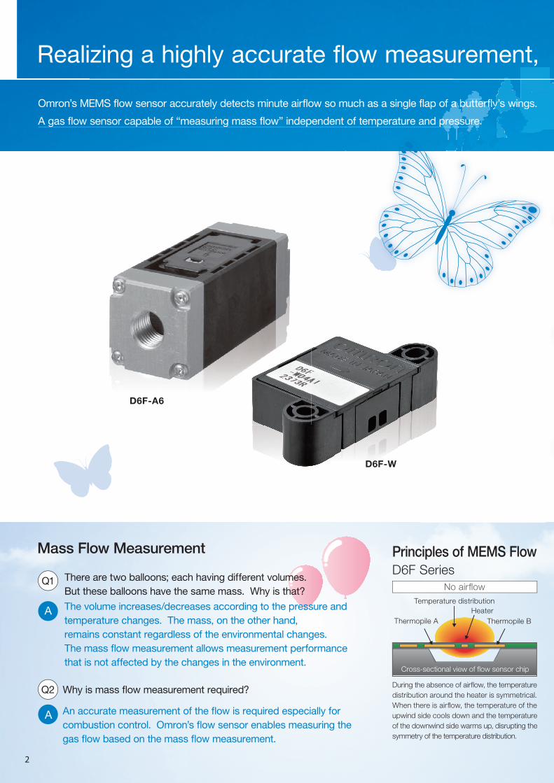
Principles of MEMS Flow D6F Series
Mass Flow Measurement
No airflow
D6F-A6
D6F-W
Omron’s MEMS flow sensor accurately detects minute airflow so much as a single flap of a butterfly’s wings.
A gas flow sensor capable of “measuring mass flow” independent of temperature and pressure.
much as a single flap of a butterfly s winy s wina butterf ngs.win
of temperature and pressure.pressure.re.
During the absence of airflow, the temperature
distribution around the heater is symmetrical.
When there is airflow, the temperature of the
upwind side cools down and the temperature
of the downwind side warms up, disrupting the
symmetry of the temperature distribution.
Q1 There are two balloons; each having different volumes.
But these balloons have the same mass. Why is that?
The volume increases/decreases according to the pressure and
temperature changes. The mass, on the other hand,
remains constant regardless of the environmental changes.
The mass flow measurement allows measurement performance
that is not affected by the changes in the environment.
A
Q2 Why is mass flow measurement required?
A An accurate measurement of the flow is required especially for
combustion control. Omron’s flow sensor enables measuring the
gas flow based on the mass flow measurement.
Realizing a highly accurate flow measurement,
2

Cross-sectional view of flow sensor chip
Principles of MEMS Flow Sensor MeasurementD6F Series
Highly Resistant to DustBuilt-in Dust Segregation System (cyclonic) D6F-W/-V/-P
AirflowExternal flow
DownwindUpwind Flow of gas
Centrifugalseparationchambers
Dust vent
MEMS sensorelement= leads the flow of clean air in here
Pattent No.4534526Energysaving
±3RD (25-100%F.S.) is realized by
linear temperature correction using
ASIC technology
HighAccuracy
Omron’s unique MEMS
technology allows
detection of very low
air velocities
HighSensitivity
The product size is reduced by using the
world-smallest class size MEMS sensor elementCompact
The sensor can be placed anywhere thanks to its dust-resistant structure. Omron’s unique design of 3D flow path provides a high level of reliability by separating dust particles to reduce its effect on the sensor chip. Additionally, Omron succeeded in reducing the sensor size, allowing it to be used in wider range of applications.
By detecting this temperature difference appearing as a difference in the electromotive forces developed by the thermopiles, it allows the mass flow rate and mass flow velocity to be measured without the influence of temperature and pressure. Since the thermopile generates the thermo-electromotive force, the power consumption is much lower than when using the resistivity method.
Flow rate of 1L: Output corresponding to flow rate change below 1/1000 of full scale.
Ambient temperature = 25degC (Model: D6F-20A7D-000-0)
Dimension of D6F-V model: 24x8x14mm.
Magnifiedview
Model : D6F-W
Out
put v
olta
ge(V
)
Flow rate(SLM)-0.2 0.0 0.2 0.4 0.6 0.8 1.0
6543210
1.04
1.02
1.00
0.98
0.96O
utpu
t vol
tage
(V)
Flow rate (sccm)-3.2 -1.6 0.0 1.6 3.2
Output voltage characteristic
1SLM =1000sccm
6%
4%
2%
0%
-2%
-4%
-6%
Error
Output voltage(V)Standard lower limit
Standard upper limit
Flow rate (L/min)0 4 8 12 16 20
Operatingcharacteristic
Realizing a highly accurate flow measurement, sensing even a single flap of a butterfly’s wings
3
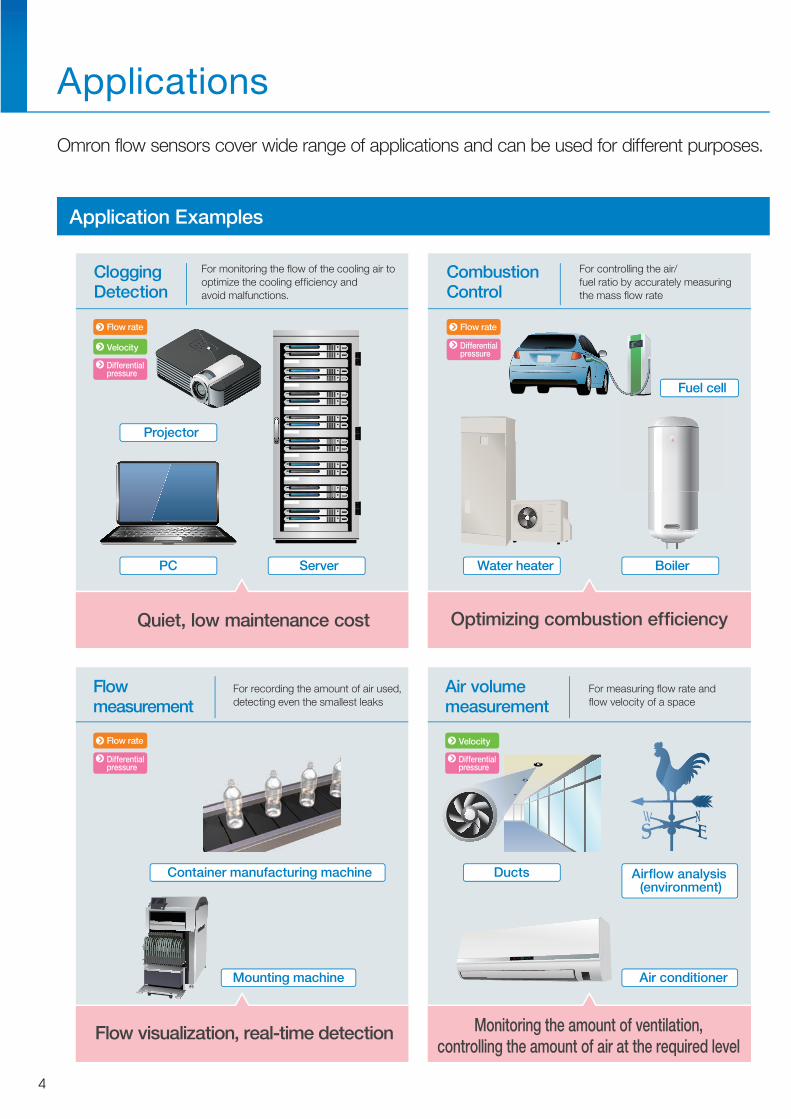
Application Examples
20 eco
Applications
Omron flow sensors cover wide range of applications and can be used for different purposes.
Quiet, low maintenance cost Optimizing combustion efficiency
Flow visualization, real-time detection Monitoring the amount of ventilation,controlling the amount of air at the required level
For monitoring the flow of the cooling air tooptimize the cooling efficiency andavoid malfunctions.
CloggingDetection
Projector
PC Server
Ducts Airflow analysis (environment)
Air conditioner
Container manufacturing machine
Mounting machine
Water heater
Fuel cell
Boiler
For controlling the air/fuel ratio by accurately measuringthe mass flow rate
CombustionControl
For recording the amount of air used,detecting even the smallest leaks
Flowmeasurement
For measuring flow rate andflow velocity of a space
Air volumemeasurement
Velocity
Flow rate
Differentialpressure
Velocity
Differentialpressure
Flow rate
Differentialpressure
Flow rate
Differentialpressure
4

1 2 3 5 10 20 50 100 200L /min
Note: The pictures are representative examples of our sensors
Selection of Products
Select the most suitable sensor from many variations.
1054321 m/s
D6F-W
D6F-V
Delivers high sensitivity evenat low flow rate, low differential pressureMEMS differentialpressure sensor
Accurate measurement
High precision
High impedance to reduce the influence ofpiping variations
Low piping effects
Detect sensor anomaly
High reliability
Flow velocity
Flow rate
Differential pressure
N2, Air
Air
Flow velocity
Typ
es o
f g
as
Natural gas, LP gas
Combustible gas
N2, Air
Air
LP gas
ble gasD6F-N2/-L2D6F-N7/-L7
are representative examples of our sensors
LP gas D6F N7/ L7
re representative examples of our sensors
21
D6F-P
D6F-A1
D6F-A3
D6F-A5/-A6/-A7/-A7DD6F-AB71/-AB71D
200L /min
10 20 50 1003 5
D6F-P( for bypass use)
D6F-PH
Flow rate
5

Items Model
Applicable gas Air
Shape
Flow rate range(L/mim)
Page
List of D6F series
MEMS Flow Sensor
D6F-P0001A1D6F-01A1-110D6F-P0010AD6F-P0010AM2
D6F-02A1-110 D6F-03A3-000
5
4
3
2
1
0
25 8 128, 25
0~3L/min0~2L/min
0~0.1L/min 0~1L/min
Items Model
Applicable gas Natural gas (13A)LP gasNatural gas (13A)
Shape
Flow rate range(L/mim)
Page
D6F-01N2-000D6F-02L2-000D6F-02L7-000
D6F-05N2-000D6F-05N7-000
5
4
3
2
1
0
10 10, 18 10, 16, 18
0~5L/min
0~2L/min0~1L/min
Items Model
Applicable gas Air
Shape
Flow rate range(L/mim)
Page
D6F-30A7-000D6F-30AB71-000
70
60
50
40
30
20
10
0
14, 16, 18, 20 14, 16, 20 18, 23 20, 23
0~70L/min
0~30L/min
0~10L/min0~20L/min
14, 16, 20
0~50L/min
Gas Minute to middle flow Analog
Air Minute flow Analog
Air Middle to high flow Analog Digital Digital type only
D6F-10A5-000D6F-10A6-000D6F-10A7-000D6F-10A7D-000
D6F-20A5-000D6F-20A6-000D6F-20A7D-000
D6F-50A5-000D6F-50A6-000D6F-50A7D-000
D6F-70AB71-000D6F-70AB71D-000
6
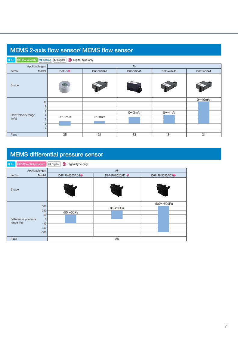
MEMS 2-axis flow sensor/ MEMS flow sensor
MEMS differential pressure sensor
Items ModelApplicable gas Air
Shape
Differential pressurerange (Pa)
Page
500250500
-50-250-500
28
-500~500Pa
-50~50Pa0~250Pa
Items ModelApplicable gas Air
Shape
Flow velocity range(m/s)
Page
D6F-W01A1 D6F-V03A1 D6F-W10A1
1086420
-2
35 31 33 31
0~10m/s
0~3m/s-1~1m/s 0~1m/s
D6F-W04A1
31
0~4m/s
Air Flow velocity Analog Digital Digital type only
Air Differential pressure Digital Digital type only
D6F-D
D6F-PH0505AD3 D6F-PH0025AD1 D6F-PH5050AD3
7

8
D6F-A1MEMS Flow Sensor
A Compact, High-accuracy Sensor That Measures Low Flow Rates.• High accuracy of ±3% FS.
• Flow rates can be measured without being affected by
temperature or pressure.
Ordering InformationMEMS Flow Sensor
Accessory (included)
ConnectionsD6F-01A1-110D6F-02A1-110
Pin No. 1: Vcc2: Vout3: GND
Connector 53398-03** (Made by Molex Japan)
Use the following connectors for connections to the D6F:Housing 51021-0300 (Made by Molex Japan)Terminals 50079 (Made by Molex Japan)Wires AWG28 to AWG26
Tubes Install tubes made of materials such as rubber or urethane so that they will not come out.For urethane tubes, tubes with an outer diameter of 12 mm and an inner diameter of 8 mm are recommended.
Output Voltage Characteristics
D6F-01A1-110
D6F-02A1-110
Measurement conditions: Power supply voltage of 12±0.1 VDC, ambient tem-perature of 25±5°C, and ambient humidity of 35% to 75%.
RoHS Compliant
Refer to the Common Precautions for the D6F Series on page 40.
Applicable fluid Flow rate range Model
Air0 to 1 L/min D6F-01A1-110
0 to 2 L/min D6F-02A1-110
Type Model
Cable D6F-CABLE1
Enlarged View
1: Vcc 3: GND
2: Vout
Flow rate L/min (normal)
0 0.2 0.4 0.6 0.8 1.0
Output voltage V
1.00±0.12
2.31±0.12
3.21±0.12
3.93±0.12
4.51±0.12
5.00±0.12
Flow rate L/min (normal)
0 0.4 0.8 1.2 1.6 2.0
Output voltage V
1.00±0.12
2.59±0.12
3.53±0.12
4.18±0.12
4.65±0.12
5.00±0.12
6.0
5.0
4.0
3.0
2.0
1.0
0.20.0 0.8 1.00.60.40.0
Out
put v
olta
ge (
V)
Flow rate (L/min)0.40.0 1.6 2.01.20.8
6.0
5.0
4.0
3.0
2.0
1.0
0.0
Out
put v
olta
ge (
V)
Flow rate (L/min)
D6F-01A1-110 D6F-02A1-110

9
D6F-A1 MEMS Flow Sensor
Characteristics/Performance
Note: 1. Volumetric flow rate at 0°C, 101.3 kPa.Note: 2. Dry gas. (must not contain large particles, e.g., dust, oil, or mist.)Note: 3. Reference (typical)Note: 4. With no condensation or icing.
Dimensions (Unit: mm)
Model D6F-01A1-110 D6F-02A1-110
Flow Range (See note 1.) 0 to 1 L/min 0 to 2 L/min.
Calibration Gas (See note 2.) Air
Flow Port TypeBamboo jointMaximum outside diameter: 8.6 mm, Minimum outside diameter: 7.4 mm
Electrical Connection Three-pin connector
Power Supply 10.8 to 26.4 VDC
Current Consumption 15 mA max with no load, with a Vcc of 12 to 24 VDC, and at 25°C
Output Voltage 1 to 5 VDC (non-linear output, load resistance of 10 kΩ)
Accuracy ±3% FS (25°C characteristic)
Repeatability (See note 3.) ±0.3% FS
Output Voltage (Max.) 5.7 VDC (Load resistance: 10 kΩ)
Output Voltage (Min.) 0 VDC (Load resistance: 10 kΩ)
Rated Power Supply Voltage 26.4 VDC
Rated Output Voltage 6 VDC
Case PPS
Degree of Protection IEC IP40 (Excluding tubing sections.)
Withstand Pressure 200 kPa
Pressure Drop (See note 3.) 0.42 kPa 1.06 kPa
Operating Temperature (See note 4.) −10 to 60°C
Operating Humidity (See note 4.) 35% to 85%
Storage Temperature (See note 4.) −40 to 80°C
Storage Humidity (See note 4.) 35% to 85%
Temperature Characteristics ±3% FS for 25°C characteristic at an ambient temperature of −10 to 60°C
Insulation Resistance Between Sensor outer cover and lead terminals: 20 MΩ min. (at 500 VDC)
Dielectric Strength Between Sensor outer cover and lead terminals: 500 VAC, 50/60 Hz min. for 1 min (leakage current: 1 mA max.)
Weight 12.8 g
3.5-dia. through hole
Through hole
7.4 dia.
(3.7)
(7.45)
4
(6)
9.54.5
R1.75
R4.253.5
20
28±0.1
20
6.54.5
0.5
4
66 4130±0.1
8
R4
8.6 dia.
15.1
30±0.05
28±0.05
Two, M3 screws
1. Vcc
2. Vout
Brown wireBlack wire
100±15
200±35
Blue wire 3. GNDConnector :51021 (Manufactured by Molex, LLC)Terminal :50079 (Manufactured by Molex, LLC)Wire :0.14SQ
D6F-01A1-110D6F-02A1-110
Mounting Hole Dimensions
Cable (included): D6F-CABLE1
10
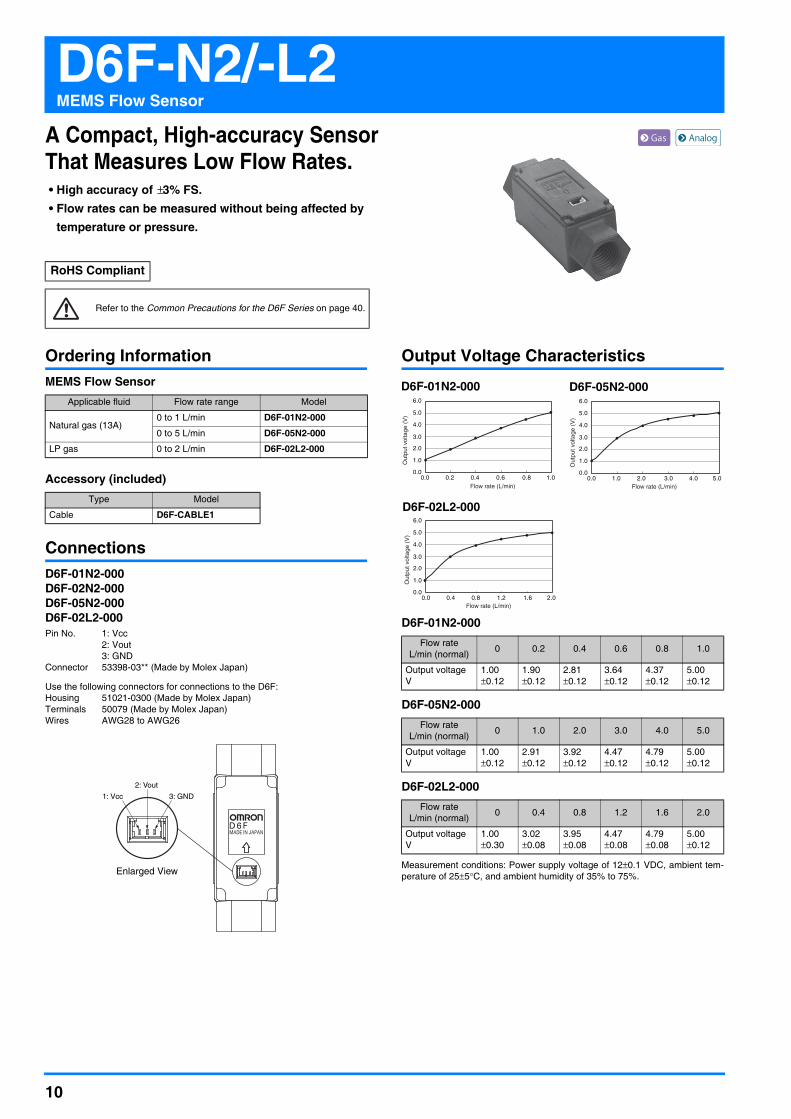
D6F-N2/-L2MEMS Flow Sensor
A Compact, High-accuracy Sensor That Measures Low Flow Rates.• High accuracy of ±3% FS.• Flow rates can be measured without being affected by
temperature or pressure.
Ordering InformationMEMS Flow Sensor
Accessory (included)
ConnectionsD6F-01N2-000D6F-02N2-000D6F-05N2-000D6F-02L2-000Pin No. 1: Vcc
2: Vout3: GND
Connector 53398-03** (Made by Molex Japan)
Use the following connectors for connections to the D6F:Housing 51021-0300 (Made by Molex Japan)Terminals 50079 (Made by Molex Japan)Wires AWG28 to AWG26
Output Voltage Characteristics
D6F-01N2-000
D6F-05N2-000
D6F-02L2-000
Measurement conditions: Power supply voltage of 12±0.1 VDC, ambient tem-perature of 25±5°C, and ambient humidity of 35% to 75%.
RoHS Compliant
Refer to the Common Precautions for the D6F Series on page 40.
Applicable fluid Flow rate range Model
Natural gas (13A)0 to 1 L/min D6F-01N2-000
0 to 5 L/min D6F-05N2-000
LP gas 0 to 2 L/min D6F-02L2-000
Type Model
Cable D6F-CABLE1
Enlarged View
1: Vcc 3: GND
2: Vout
Flow rate L/min (normal) 0 0.2 0.4 0.6 0.8 1.0
Output voltage V
1.00±0.12
1.90±0.12
2.81±0.12
3.64±0.12
4.37±0.12
5.00±0.12
Flow rate L/min (normal) 0 1.0 2.0 3.0 4.0 5.0
Output voltage V
1.00±0.12
2.91±0.12
3.92±0.12
4.47±0.12
4.79±0.12
5.00±0.12
Flow rate L/min (normal) 0 0.4 0.8 1.2 1.6 2.0
Output voltage V
1.00±0.30
3.02±0.08
3.95±0.08
4.47±0.08
4.79±0.08
5.00±0.12
0.20.0 0.8 1.00.60.4
6.0
5.0
4.0
3.0
2.0
1.0
0.0
Out
put v
olta
ge (
V)
Flow rate (L/min)1.00.0 4.0 5.03.02.0
6.0
5.0
4.0
3.0
2.0
1.0
0.0
Out
put v
olta
ge (
V)
Flow rate (L/min)
0.40.0 1.6 2.01.20.8
6.0
5.0
4.0
3.0
2.0
1.0
0.0
Out
put v
olta
ge (
V)
Flow rate (L/min)
D6F-01N2-000 D6F-05N2-000
D6F-02L2-000

11
D6F-N2/-L2 MEMS Flow Sensor
Characteristics/Performance
Note: 1. Volumetric flow rate at 0°C, 101.3 kPa.Note: 2. Dry gas. (must not contain large particles, e.g., dust, oil, or mist.)Note: 3. Reference (typical)Note: 4. With no condensation or icing.
Dimensions (Unit: mm)
Model D6F-01N2-000 D6F-05N2-000 D6F-02L2-000
Flow Range (See note 1.) 0 to 1 L/min 0 to 5 L/min 0 to 2 L/min.
Calibration Gas (See note 2.) Natural gas (13A) Propane gas
Flow Port Type Rc 1/4 thread
Electrical Connection Three-pin connector
Power Supply 10.8 to 26.4 VDC
Current Consumption 15 mA max. with no load, with a Vcc of 12 to 24 VDC, and at 25°C
Output Voltage 1 to 5 VDC (non-linear output, load resistance of 10 kΩ)
Accuracy ±3% FS (25°C characteristic) ±2% to ±7.5% F.S. (25°C characteristic)
Repeatability (See note 3.) ±0.2% FS ±0.3% FS
Output Voltage (Max.) 5.7 VDC (Load resistance: 10 kΩ)
Output Voltage (Min.) 0 VDC (Load resistance: 10 kΩ)
Rated Power Supply Voltage 26.4 VDC
Rated Output Voltage 6 VDC
Case Aluminum alloy
Degree of Protection IEC IP40 (Excluding tubing sections.)
Withstand Pressure 200 kPa
Pressure Drop (See note 3.) 0.017 kPa 0.10 kPa 0.14 kPa
Operating Temperature (See note 4.) −10 to 60°C
Operating Humidity (See note 4.) 35% to 85%
Storage Temperature (See note 4.) −40 to 80°C
Storage Humidity (See note 4.) 35% to 85%
Temperature Characteristics ±3% FS for 25°C characteristic at −10 to 60°C±4% FS for 25°C characteristic at −10
to 60°C
Insulation Resistance Between Sensor outer cover and lead terminals: 20 MΩ min. (at 500 VDC)
Dielectric Strength Between Sensor outer cover and lead terminals: 500 VAC, 50/60 Hz min. for 1 min (leakage current: 1 mA max.)
Weight 35.3 g
(6)
21.6±0.5
3-17
22.1±0.5
Two, tapped threads for Rc 1/4 pipe
0.35
10 10
1. Vcc
2. Vout
Brown wireBlack wire
100±15
200±35
Blue wire 3. GND
8.85
62±0.5
(3.7)
16.2Two, M3 holes with a depth of at least 5 mm
37
37±0.05
16.2±0.05 Two, 3.5 dia.
Connector :51021 (Manufactured by Molex, LLC)Terminal :50079 (Manufactured by Molex, LLC)Wire :0.14SQ
D6F-01N2-000D6F-05N2-000D6F-02L2-000 Mounting Hole Dimensions
Cable (included): D6F-CABLE1
12
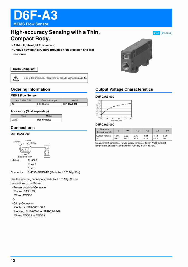
D6F-A3MEMS Flow Sensor
High-accuracy Sensing with a Thin, Compact Body.• A thin, lightweight flow sensor.
• Unique flow path structure provides high precision and fast
response.
Ordering InformationMEMS Flow Sensor
Accessory (Sold separately)
ConnectionsD6F-03A3-000
Pin No. 1: GND
2: Vout
3: Vcc
Connector SM03B-SRSS-TB (Made by J.S.T. Mfg. Co.)
Use the following connectors made by J.S.T. Mfg. Co. for
connections to the Sensor:
• Pressure-welded ConnectorSocket: 03SR-3S
Wires: AWG30
Or
• Crimp ConnectorContacts: SSH-003T-P0.2
Housing: SHR-03V-S or SHR-03V-S-B
Wires: AWG32 to AWG28
Output Voltage Characteristics
D6F-03A3-000
Measurement conditions: Power supply voltage of 12±0.1 VDC, ambient temperature of 25±5°C, and ambient humidity of 35% to 75%.
RoHS Compliant
Refer to the Common Precautions for the D6F Series on page 40.
Applicable fluid Flow rate range Model
Air 0 to 3 L/min D6F-03A3-000
Type Model
Cable D6F-CABLE2
3: Vcc1: GND
Enlarged View
2: Vout
Flow rate L/min (normal)
0 0.6 1.2 1.8 2.4 3.0
Output voltage V
1.00±0.2
2.83±0.2
3.77±0.2
4.34±0.2
4.72±0.2
5.00±0.2
0.60.0 2.4 3.01.81.2
6.0
5.0
4.0
3.0
2.0
1.0
0.0
Out
put v
olta
ge (
V)
Flow rate (L/min)
D6F-03A3-000

13
D6F-A3 MEMS Flow Sensor
Characteristics/Performance
Note: 1. Volumetric flow rate at 0°C, 101.3 kPa.Note: 2. Dry gas. (must not contain large particles, e.g., dust, oil, or mist.)Note: 3. Reference (typical)Note: 4. With no condensation or icing.
Dimensions (Unit: mm)
● MEMS Flow Sensors
D6F-03A3-000
● Cable (Sold separately)
D6F-CABLE2
Model D6F-03A3-000
Flow Range (See note 1.) 0 to 3 L/min
Calibration Gas (See note 2.) Air
Flow Port Type M5 thread
Electrical Connection Three-pin connector
Power Supply 10.8 to 26.4 VDC
Current Consumption 15 mA max. with no load, with a Vcc of 12 to 24 VDC, and at 25°C
Output Voltage 1 to 5 VDC (non-linear output, load resistance of 10 kΩ)
Accuracy ±5% FS (25°C characteristic)
Repeatability (See note 3.) ±0.7% FS
Output Voltage (Max.) 5.7 VDC (Load resistance: 10 kΩ)
Output Voltage (Min.) 0 VDC (Load resistance: 10 kΩ)
Rated Power Supply Voltage 26.4 VDC
Rated Output Voltage 6 VDC
Case PPS
Degree of Protection IEC IP40 (Excluding tubing sections.)
Withstand Pressure 200 kPa
Pressure Drop (See note 3.) 0.45 kPa
Operating Temperature (See note 4.) 0 to 50°C
Operating Humidity (See note 4.) 35% to 85%
Storage Temperature (See note 4.) −10 to 60°C
Storage Humidity (See note 4.) 35% to 85%
Temperature Characteristics ±5% FS for 25°C characteristic at an ambient temperature of 0 to 50°C
Insulation Resistance Between Sensor outer cover and lead terminals: 20 MΩ min. (at 500 VDC)
Dielectric Strength Between Sensor outer cover and lead terminals: 500 VAC, 50/60 Hz min. for 1 min (leakage current: 1 mA max.)
Weight 5.3 g
MADE IN JAPAN IN side OUT side D6F -03A3-000
M5 threads (Effective thread depth: 3.1)
3.1 +0.15 −0.05
+0.15 −0.05
3.4-dia. 18±0.15
36.6
14 16.8
3.1 dia. through hole
8
6.8
18±0.05Two,
M3 screw holes
Mounting Hole Dimensions
15±3(5)
180±10
3: GND
2: Vout
White wireBlack wire
Red wire 1: Vcc
Contact :SSH-003T-P0.2 (Manufactured by J.S.T. Mfg. Co., Ltd.)Housing :SHR-03V-S (Manufactured by J.S.T. Mfg. Co., Ltd.)Wire :AWG#30

14
D6F-A5MEMS Flow Sensor
High-accuracy Sensing with a Compact Body for Flow Rates Up to 50 L/min.• Accurately detects a mass flow rate of 10 to 50 L/min.
• A compact size of 30 × 78 × 30 mm (H × W × D).
Ordering InformationMEMS Flow Sensor
Accessory (Sold separately)
ConnectionsD6F-10A5-000D6F-20A5-000D6F-50A5-000
Output Voltage Characteristics
D6F-10A5-000
D6F-20A5-000
D6F-50A5-000
Measurement conditions: Power supply voltage of 12±0.1 VDC, ambient temperature of 25±5°C, and ambient humidity of 35% to 75%.
RoHS Compliant
Refer to the Common Precautions for the D6F Series on page 40.
Flow Port Type Applicable fluid Flow rate range Model
Manifold Air
0 to 10 L/min D6F-10A5-000
0 to 20 L/min D6F-20A5-000
0 to 50 L/min D6F-50A5-000
Type Model
Cable D6F-CABLE1
Enlarged View
3: GND2: Vout1: Vcc
Pin No. 1: Vcc2: Vout3: GND
Connector 53398-03** (Made by Molex Japan)
Use the following connectors for connections to the D6F:Housing 51021-0300 (Made by Molex Japan)Terminals 50079 (Made by Molex Japan)Wires AWG28 to AWG26
Flow rate L/min (normal)
0 2.0 4.0 6.0 8.0 10.0
Output voltage V
1.00±0.12
1.75±0.12
2.60±0.12
3.45±0.12
4.25±0.12
5.00±0.12
Flow rate L/min (normal)
0 4.0 8.0 12.0 16.0 20.0
Output voltage V
1.00±0.12
1.93±0.12
2.87±0.12
3.70±0.12
4.41±0.12
5.00±0.12
Flow rate L/min (normal)
0 10 20 30 40 50
Output voltage V
1.00±0.12
2.45±0.12
3.51±0.12
4.20±0.12
4.66±0.12
5.00±0.12
6.0
5.0
4.0
3.0
2.0
1.0
2.00.0 8.0 10.06.04.00.0
Out
put v
olta
ge (
V)
Flow rate (L/min)4.00.0 16.0 20.012.08.0
6.0
5.0
4.0
3.0
2.0
1.0
0.0
Out
put v
olta
ge (
V)
Flow rate (L/min)
10.00.0 40.0 50.030.020.0
6.0
5.0
4.0
3.0
2.0
1.0
0.0
Out
put v
olta
ge (
V)
Flow rate (L/min)
D6F-10A5-000 D6F-20A5-000
D6F-50A5-000

15
D6F-A5 MEMS Flow Sensor
Characteristics/Performance
Note: 1. Volumetric flow rate at 0°C, 101.3 kPa.Note: 2. Dry gas. (must not contain large particles, e.g., dust, oil, or mist.)Note: 3. Reference (typical)Note: 4. With no condensation or icing.
Dimensions (Unit: mm)
● MEMS Flow Sensors
● Cable (Sold separately)D6F-CABLE1
Model D6F-10A5-000 D6F-20A5-000 D6F-50A5-000
Flow Range (See note 1.) 0 to 10 L/min 0 to 20 L/min 0 to 50 L/min
Calibration Gas (See note 2.) Air
Flow Port Type Manifold
Electrical Connection Three-pin connector
Power Supply 10.8 to 26.4 VDC
Current Consumption 15 mA max. with no load, with a Vcc of 12 to 24 VDC, and at 25°C
Output Voltage 1 to 5 VDC (non-linear output, load resistance of 10 kΩ)
Accuracy ±3% FS (25°C characteristic)
Repeatability (See note 3.) ±0.3% FS
Output Voltage (Max.) 5.7 VDC (Load resistance: 10 kΩ)
Output Voltage (Min.) 0 VDC (Load resistance: 10 kΩ)
Rated Power Supply Voltage 26.4 VDC
Rated Output Voltage 6 VDC
Case PPS/aluminum alloy
Degree of Protection IEC IP40 (Excluding tubing sections.)
Withstand Pressure 500 kPa
Pressure Drop (See note 3.) 0.8 kPa 2.9 kPa 17.2 kPa
Operating Temperature (See note 4.) −10 to 60°C
Operating Humidity (See note 4.) 35% to 85%
Storage Temperature (See note 4.) −30 to 80°C
Storage Humidity (See note 4.) 35% to 85%
Temperature Characteristics ±3% FS for 25°C characteristic at an ambient temperature of −10 to 60°C
Insulation Resistance Between Sensor outer cover and lead terminals: 20 MΩ min. (at 500 VDC)
Dielectric Strength Between Sensor outer cover and lead terminals: 500 VAC, 50/60 Hz min. for 1 min (leakage current: 1 mA max.)
Weight 103 g
(30.05)
30±0.5
66±0.1 66±0.05
14±0.05
Four, M3 holes
Two, 1.4±0.1Four, 3.2-dia. through holes Lot number label
Two, 5 dia.
30±0.5
78±0.5
(6)
(3.7)
6
Mounting Hole Dimensions
D6F-10A5-000D6F-20A5-000D6F-50A5-000
1. Vcc
2. Vout
Brown wireBlack wire
100±15
200±35
Blue wire 3. GND
Connector :51021 (Manufactured by Molex, LLC)Terminal :50079 (Manufactured by Molex, LLC)Wire :0.14SQ

16
D6F-A6MEMS Flow Sensor
High-accuracy Sensing with a Compact Body for Flow Rates up to 50 L/min.• Accurately measures an air mass flow rate of 10 to 50 L/min.
• A compact size of 30 × 78 × 30 mm (H × W × D).
Ordering InformationMEMS Flow Sensor
Accessory (Sold separately)
ConnectionsD6F-10A6-000 D6F-10A61-000D6F-20A6-000 D6F-20A61-000D6F-50A6-000 D6F-50A61-000D6F-50A62-000
Output Voltage Characteristics
D6F-10A6-000/D6F-10A61-000
D6F-20A6-000/D6F-20A61-000
D6F-50A6-000/D6F-50A61-000/D6F-50A62-000
Measurement conditions: Power supply voltage of 12±0.1 VDC, ambient temperature of 25±5°C, and ambient humidity of 35% to 75%.
RoHS Compliant
Refer to the Common Precautions for the D6F Series on page 40.
Flow Port Type Applicable fluid Flow rate range Model
Rc 1/4 thread
Air
0 to 10 L/min D6F-10A6-000
0 to 20 L/min D6F-20A6-000
0 to 50 L/min D6F-50A6-000
NPT 1/8 thread
0 to 10 L/min D6F-10A61-000
0 to 20 L/min D6F-20A61-000
0 to 50 L/min D6F-50A61-000
NPT 1/2 thread 0 to 50 L/min D6F-50A62-000
Type Model
Cable D6F-CABLE1
Enlarged View
3: GND2: Vout1: Vcc
Pin No. 1: Vcc2: Vout3: GND
Connector 53398-03** (Made by Molex Japan)
Use the following connectors for connections to the D6F:Housing 51021-0300 (Made by Molex Japan)Terminals 50079 (Made by Molex Japan)Wires AWG28 to AWG26
Flow rate L/min (normal)
0 2.0 4.0 6.0 8.0 10.0
Output voltage V
1.00±0.12
1.75±0.12
2.60±0.12
3.45±0.12
4.25±0.12
5.00±0.12
Flow rate L/min (normal)
0 4 8 12 16 20
Output voltage V
1.00±0.12
1.93±0.12
2.87±0.12
3.70±0.12
4.41±0.12
5.00±0.12
Flow rate L/min (normal)
0 10 20 30 40 50
Output voltage V
1.00±0.12
2.45±0.12
3.51±0.12
4.20±0.12
4.66±0.12
5.00±0.12
6.0
5.0
4.0
3.0
2.0
1.0
2.00.0 8.0 10.06.04.00.0O
utpu
t vol
tage
(V
)
Flow rate (L/min)4.00.0 16.0 20.012.08.0
6.0
5.0
4.0
3.0
2.0
1.0
0.0
Out
put v
olta
ge (
V)
Flow rate (L/min)
10.00.0 40.0 50.030.020.0
6.0
5.0
4.0
3.0
2.0
1.0
0.0
Out
put v
olta
ge (
V)
Flow rate (L/min)
D6F-10A6-000D6F-10A61-000
D6F-20A6-000D6F-20A61-000
D6F-50A6-000D6F-50A61-000D6F-50A62-000

17
D6F-A6 MEMS Flow Sensor
Characteristics/Performance
Note: 1. Volumetric flow rate at 0°C, 101.3 kPa.Note: 2. Dry gas. (must not contain large particles, e.g., dust, oil, or mist.)Note: 3. Reference (typical)Note: 4. With no condensation or icing.
Dimensions (Unit: mm)
● MEMS Flow Sensors
Model D6F-10A6-000 D6F-20A6-000 D6F-50A6-000 D6F-10A61-000 D6F-20A61-000 D6F-50A61-000 D6F-50A62-000
Flow Range (See note 1.) 0 to 10 L/min 0 to 20 L/min 0 to 50 L/min 0 to 10 L/min 0 to 20 L/min 0 to 50 L/min 0 to 50 L/min
Calibration Gas (See note 2.) Air
Flow Port Type Rc 1/4 thread NPT 1/8 thread NPT 1/2 thread
Electrical Connection Three-pin connector
Power Supply 10.8 to 26.4 VDC
Current Consumption 15 mA max. with no load, with a Vcc of 12 to 24 VDC, and at 25°C
Output Voltage 1 to 5 VDC (non-linear output, load resistance of 10kΩ min.)
Accuracy ±3% FS (25°C characteristic)
Repeatability (See note 3.) ±0.3% FS
Output Voltage (Max.) 5.7 VDC (Load resistance: 10 kΩ)
Output Voltage (Min.) 0 VDC (Load resistance: 10 kΩ)
Rated Power Supply Voltage 26.4 VDC
Rated Output Voltage 6 VDC
Case PPS/aluminum alloy
Degree of Protection IEC IP40 (Excluding tubing sections.)
Withstand Pressure 500 kPa
Pressure Drop (See note 3.) 0.10 kPa 0.28 kPa 1.44 kPa 0.15 kPa 0.52 kPa 2.31 kPa 2.16 kPa
Operating Temperature (See note 4.) −10 to 60°C
Operating Humidity (See note 4.) 35% to 85%
Storage Temperature (See note 4.) −30 to 80°C
Storage Humidity (See note 4.) 35% to 85%
Temperature Characteristics ±3% FS for 25°C characteristic at an ambient temperature of −10 to 60°C
Insulation Resistance Between Sensor outer cover and lead terminals: 20 MΩ min. (at 500 VDC)
Dielectric Strength Between Sensor outer cover and lead terminals: 500 VAC, 50/60 Hz min. for 1 min (leakage current: 1 mA max.)
Weight 103 g
(30.4)
30±0.5
66±0.2
12±0.2
30±0.5
78±0.5
(6)
(3.7)
6 Two, tapped threads for Rc 1/4 pipes
30±0.5
30±0.5
Two, tapped threads for NPT 1/8 pipes
Two, M3 holes, Effective screw depth: 4.5
66±0.05
12±0.05
Two, 3.2-dia. HolesLot number label
(6)
92
(37.05)
(3.7)
66
13
12Lot number label
Two, M3 holes, Effective screw depth: 2.5
30±0.5
30±0.5
Two, tapped threads for NPT 1/2 pipes
Mounting Hole Dimensions
D6F-10A6-000D6F-20A6-000D6F-50A6-000
D6F-10A61-000D6F-20A61-000D6F-50A61-000
D6F-50A62-000
[Models Other Than D6F-50A62 Models] [D6F-50A62]
● Cable (Sold separately)D6F-CABLE1
1. Vcc
2. Vout
Brown wireBlack wire
100±15
200±35
Blue wire 3. GND
Connector :51021 (Manufactured by Molex, LLC)Terminal :50079 (Manufactured by Molex, LLC)Wire :0.14SQ

18
D6F-A7/-L7/-N7MEMS Flow Sensor
Reduction of Piping time by quick joint connection• Low -flow rate of natural gas and LP gas can be measured.
• 10 L/min and 30 L/min of Air can be measured.
• Compact size of 30 × 84.6 × 30 mm (H × W × D).
Ordering InformationMEMS Flow Sensor
Accessories (Sold separately)
ConnectionsD6F-05N7-000 D6F-02L7-000D6F-10A7-000 D6F-30A7-000
Output Voltage Characteristics
D6F-05N7-000
D6F-02L7-000
D6F-10A7-000
D6F-30A7-000
Measurement conditions: Power-supply voltage 12±0.1 VDC, ambient temper-ature 25±5°C and ambient humidity 35 to 75%RH.
RoHS Compliant
Refer to the Common Precautions for the D6F Series on page 40.
Flow Port Type Applicable fluid Flow rate range Model
Quick joint P10
Natural gas (13A) 0 to 5 L/min D6F-05N7-000
LP gas 0 to 2 L/min D6F-02L7-000
Air0 to 10 L/min D6F-10A7-000
0 to 30 L/min D6F-30A7-000
Type Model
Cable D6F-CABLE1
Quick fastener D6F-FASTENER-P10
Enlarged View
3:GND2:Vout1:Vcc
Pin No. 1: Vcc2: Vout3: GND
Connector 53398-03** (Made by Molex Japan)
Use the following connectors for connections to the D6F:Housing 51021-0300 (Made by Molex Japan)Terminals 50079 (Made by Molex Japan)Wires AWG28 to AWG26
Flow rateL/min (normal)
0 1.0 2.0 3.0 4.0 5.0
Output voltageV
1.00±0.12
1.68±0.12
2.47±0.12
3.31±0.12
4.15±0.12
5.00±0.12
Flow rateL/min (normal)
0 0.4 0.8 1.2 1.6 2.0
Output voltageV
1.00±0.12
1.96±0.12
2.89±0.12
3.72±0.12
4.43±0.12
5.00±0.12
Flow rateL/min (normal)
0 2.0 4.0 6.0 8.0 10.0
Output voltageV
1.00±0.12
1.75±0.12
2.60±0.12
3.45±0.12
4.25±0.12
5.00±0.12
Flow rateL/min (normal)
0 6 12 18 24 30
Output voltageV
1.00±0.12
2.11±0.12
3.12±0.12
3.91±0.12
4.53±0.12
5.00±0.12
6.0
5.0
4.0
3.0
2.0
1.0
1.00.0 4.0 5.03.02.00.0
Flow rate (L/min)
Out
put v
olta
ge (
V)
6.0
5.0
4.0
3.0
2.0
1.0
0.40.0 1.6 2.01.20.80.0
Flow rate (L/min)
Out
put v
olta
ge (
V)
6.0
5.0
4.0
3.0
2.0
1.0
20 8 10640.0
Flow rate (L/min)
Out
put v
olta
ge (
V)
D6F-05N7-000 D6F-02L7-000
D6F-10A7-0006.0
5.0
4.0
3.0
2.0
1.0
60 24 3018120.0
Flow rate (L/min)
Out
put v
olta
ge (
V)
D6F-30A7-000

19
D6F-A7/-L7/-N7 MEMS Flow Sensor
Characteristics/Performance
Note: 1. Volumetric flow rate at 0°C, 101.3 kPa.Note: 2. Dry gas (must not contain large particles, e.g., dust, oil, or mist.)Note: 3. Reference (typical)Note: 4. With no condensation or icing.
Dimensions (Unit: mm)
Model D6F-05N7-000 D6F-02L7-000 D6F-10A7-000 D6F-30A7-000
Flow Range (See note 1.) 0 to 5 L/min 0 to 2 L/min 0 to 10 L/min 0 to 30 L/min
Calibration Gas (See note 2.) Natural gas (13A) LP gas Air
Flow Port Type Quick joint P10
Electrical Connection Three-pin connector
Power Supply 10.8 to 26.4 VDC
Current Consumption 15 mA max. with no load and Vcc of 12 to 24 VDC, GND = 0 VDC, 25°C
Output Voltage 1 to 5 VDC (non-linear output, load resistance of 10 kΩ min.)
Accuracy ±3%F.S. (25°C characteristic)
Repeatability (See note 3.) ±0.3%F.S.
Output Voltage (Max.) 5.7 VDC (Load resistance: 10 kΩ)
Output Voltage (Min.) 0 VDC (Load resistance: 10 kΩ)
Rated Power Supply Voltage 26.4 VDC
Rated Output Voltage 6 VDC
Case PPS
Degree of Protection IEC IP40 (Excluding tubing sections.)
Withstand Pressure 500 kPa
Pressure Drop (See note 3.) 0.06 kPa 0.03 kPa 0.32 kPa 2.19 kPa
Operating Temperature (See note 4.) –10 to +60°C
Operating Humidity (See note 4.) 35 to 85%RH
Storage Temperature (See note 4.) –10 to +80°C –30 to +80°C
Storage Humidity (See note 4.) 35 to 85%RH
Temperature Characteristics ±3%F.S. for 25°C characteristic at an ambient temperature of –10 to +60°C
Insulation Resistance Between sensor outer cover and lead terminals: 20 MΩ min. (at 500 VDC)
Dielectric Strength Between sensor outer cover and lead terminals: 500 VAC, 50/60 Hz min. for 1 min (leakage current: 1 mA max.)
Weight 72 g
6±0.3
3±0.15
C0.5 (circumference)
0.9
30°
C0.5 (circumference)R2 (circumference)
20 dia.17 dia.
13 dia.+0.1-0.05
60.664.5
66.684.6±0.5
(6)
(3.7)
(33.4)
30±0.5
30±0.5
Note
Lot No. DisplayA
CROSS A-A
A
● MEMS Flow SensorsD6F-05N7-000D6F-02L7-000D6F-10A7-000D6F-30A7-000
Note. The Port type of pipe fitting based on “Quick Joint P10 Type”.* P10 shows the name of an O-ring prescribed by JIS B 2401.* The port of O-ring ditch is based on P10 of JIS B 2406.* Please obtain a male joint separately.
If using a Rc3/8 converter joint, the following is recommended.REGAL JOINT CO., LTD [email protected] Converter male joint (Rc3/8-Quick male joint): Adapter Rc3/8-QJM10 O ring: O ring P10 fluororubber (material)
9 max.
1.6 max2.5±0.05
2 min. 2 min.
C0.3C0.5
R0.4R0.4
C0.1
2.5 +0.25-0
CROSS X-X Description Y
Y
X X
12.85±0.05 dia.20 dia.
17 dia.max.
10 dia.+0-0.05
Recommended Quick joint male P10 type
“10” is engraved here.
16.5±2
3.3
4-R1.5
8-R2.5
2-R1
t=0.8±0.04
2-R2
1R8.5
R8.5
11.5±1
15±13±0.15
1411
12±0.15
6±0.15
3
8±0.3
1
2-R2
Return directionRolling direction
● Quick fastener (Sold separately)D6F-FASTENER-P10
1. Vcc
2. Vout
Brown wireBlack wire
100±15
200±35
Blue wire 3. GNDConnector :51021 (Manufactured by Molex, LLC)Terminal :50079 (Manufactured by Molex, LLC)Wire :0.14SQ
● Cable (Sold separately)D6F-CABLE1

20
D6F-A7D/-AB71DMEMS Flow Sensor
Digital Compensation for High Accuracy• Temperature compensation and linear compensation produce
high accuracy (±3% RD (25% to 100% FS)).
• Compact models for 10 to 70 L/min.
• Reduced piping work with quick-fastening feature.
Ordering InformationMEMS Flow Sensor
Accessories (Sold separately)
ConnectionsD6F-10A7D-000-0D6F-20A7D-000-0D6F-50A7D-000-0D6F-70AB71D-000-0
Output Characteristics
D6F-10A7D-000-0
Measurement conditions: Power-supply voltage 3.3±0.1 VDC, ambient temper-ature 25±5°C and ambient humidity 35 to 75%RH.Flow rate = (Output value - 1,024)/60,000 x 10
D6F-20A7D-000-0
Measurement conditions: Power-supply voltage 3.3±0.1 VDC, ambient temper-ature 25±5°C and ambient humidity 35 to 75%RH.Flow rate = (Output value - 1,024)/60,000 x 20
D6F-50A7D-000-0
Measurement conditions: Power-supply voltage 3.3±0.1 VDC, ambient temper-ature 25±5°C and ambient humidity 35 to 75%RH.Flow rate = (Output value - 1,024)/60,000 x 50
D6F-70AB71D-000-0
Measurement conditions: Power-supply voltage 3.3±0.1 VDC, ambient temper-ature 25±5°C and ambient humidity 35 to 75%RH.Flow rate = (Output value - 1,024)/60,000 x 100
RoHS Compliant
Refer to the Common Precautions for the D6F Series on page 40.
Joint Applicable fluid Flow rate range Model
Quick joint P10Air
0 to 10 L/min D6F-10A7D-000-0
0 to 20 L/min D6F-20A7D-000-0
0 to 50 L/min D6F-50A7D-000-0
Quick joint P14 0 to 70 L/min D6F-70AB71D-000-0
Type Model
Cable D6F-CABLE3
Quick fastener D6F-FASTENER-P10
Enlarged View
1: Vcc
2: SDA3: SCL
4: GND
Pin No. 1: Vcc2: SDA3: SCL4: GND
Connector GHR-04V-S (made by J.S.T. Mfg. Co.)
Use the following connectors for connections to the D6F:Housing GHR-04V-S (made by J.S.T. Mfg. Co.)Terminals SSHL-002T-P0.2 (made by J.S.T. Mfg. Co.)Wires AWG26 to AWG30
Flow rateL/min (normal)
0 2 4 6 8 10
Output voltage(HEX)
1024(0400)
13024(32E0)
25024(61C0)
37024(90A0)
49024(BF80)
61024(EE60)
Flow rateL/min (normal)
0 4 8 12 16 20
Output voltage(HEX)
1024(0400)
13024(32E0)
25024(61C0)
37024(90A0)
49024(BF80)
61024(EE60)
Flow rateL/min (normal)
0 10 20 30 40 50
Output voltage(HEX)
1024(0400)
13024(32E0)
25024(61C0)
37024(90A0)
49024(BF80)
61024(EE60)
Flow rateL/min (normal)
0 20 40 60 70
Output voltage(HEX)
1024(0400)
13024(32E0)
25024(61C0)
37024(90A0)
43024(A810)
Flow rate (L/min)
70000
60000
50000
40000
30000
20000
10000
20 8 10640
Out
put (
Cou
nt)
Out
put (
Cou
nt)
Flow rate (L/min)
70000
60000
50000
40000
30000
20000
10000
0 15 201050
Out
put (
Cou
nt)
Flow rate (L/min)
70000
60000
50000
40000
30000
20000
10000
100 40 5030200
D6F-10A7D-000-0 D6F-20A7D-000-0
D6F-50A7D-000-0
Out
put (
Cou
nt)
Flow rate (L/min)
50000
40000
30000
20000
10000
100 40 7050 6030200
D6F-70AB71D-000-0

21
D6F-A7D/-AB71D MEMS Flow Sensor
Characteristics/Performance
Note: 1. Volumetric flow rate at 0°C, 101.3 kPa.Note: 2. Dry gas (must not contain large particles, e.g., dust, oil, or mist.)Note: 3. -10 ≤ Operating Temperature ≤ 60°CNote: 4. Reference (typical)Note: 5. Refer to the D6F-@@@@D-000-@ Application Notes for details.Note: 6. With no condensation or icing.Note: 7. The following custom options are available.
Ask your OMRON representative for details.- Temperature measurement - Address settings (up to four addresses)- Fault detection- Threshold setting
Communication
Model D6F-10A7D-000-0 D6F-20A7D-000-0 D6F-50A7D-000-0 D6F-70AB71D-000-0
Flow Range (See note 1.) 0 to 10L/min 0 to 20 L/min 0 to 50 L/min 0 to 70 L/min
Calibration Gas (See note 2.) Air
Flow Port Type Quick joint P10 Quick joint P14
Electrical Connection Four-pin connector
Power Supply 3.0 to 3.6 VDC
Current Consumption 10 mA max. with no load, Vcc = 3.3 VDC, GND = 0 VDC, 25°C
Resolution 15 bit
Accuracy (See note 3.)±5%RD (10%F.S. ≤ Flow rate < 25%F.S.)±3%RD (25%F.S. ≤ Flow rate ≤ 100%F.S.)
±5%RD (10L/min ≤ Flow rate < 20L/min)±3%RD (20L/min ≤ Flow rate ≤ 70L/min)
Response time 90 ms max.
Repeatability (See note 4.) 0.3 %RD 0.3%RD 0.5%RD 1.3%RD
Interface (See note 5.) I2C
Case PPS
Degree of Protection IEC IP40 (Excluding tubing sections.)
Withstand Pressure 100 kPa
Pressure Drop (See note 4.) 0.034 kPa 0.083 kPa 0.28 kPa 0.57 kPa
Operating Temperature (See note 6.) –10 to +60°C
Operating Humidity (See note 6.) 35 to 85%RH
Storage Temperature (See note 6.) –30 to +80°C
Storage Humidity (See note 6.) 35 to 85%RH
Insulation Resistance Between sensor outer cover and lead terminals: 20 MΩ min. (at 500 VDC)
Dielectric Strength Between sensor outer cover and lead terminals: 500 VAC, 50/60 Hz min. for 1 min (leakage current: 1 mA max.)
Weight 57.3 g 64.4 g
Serial Interface I2C
Master/SlaveSlave / Address: HEX : 0x6C
BIN : 110_1100 (7bit)
Speed mode Fast Mode 400kHz
Signal
SCL Serial Clock
SDA Data Signal
22
D6F-A7D/-AB71D MEMS Flow Sensor
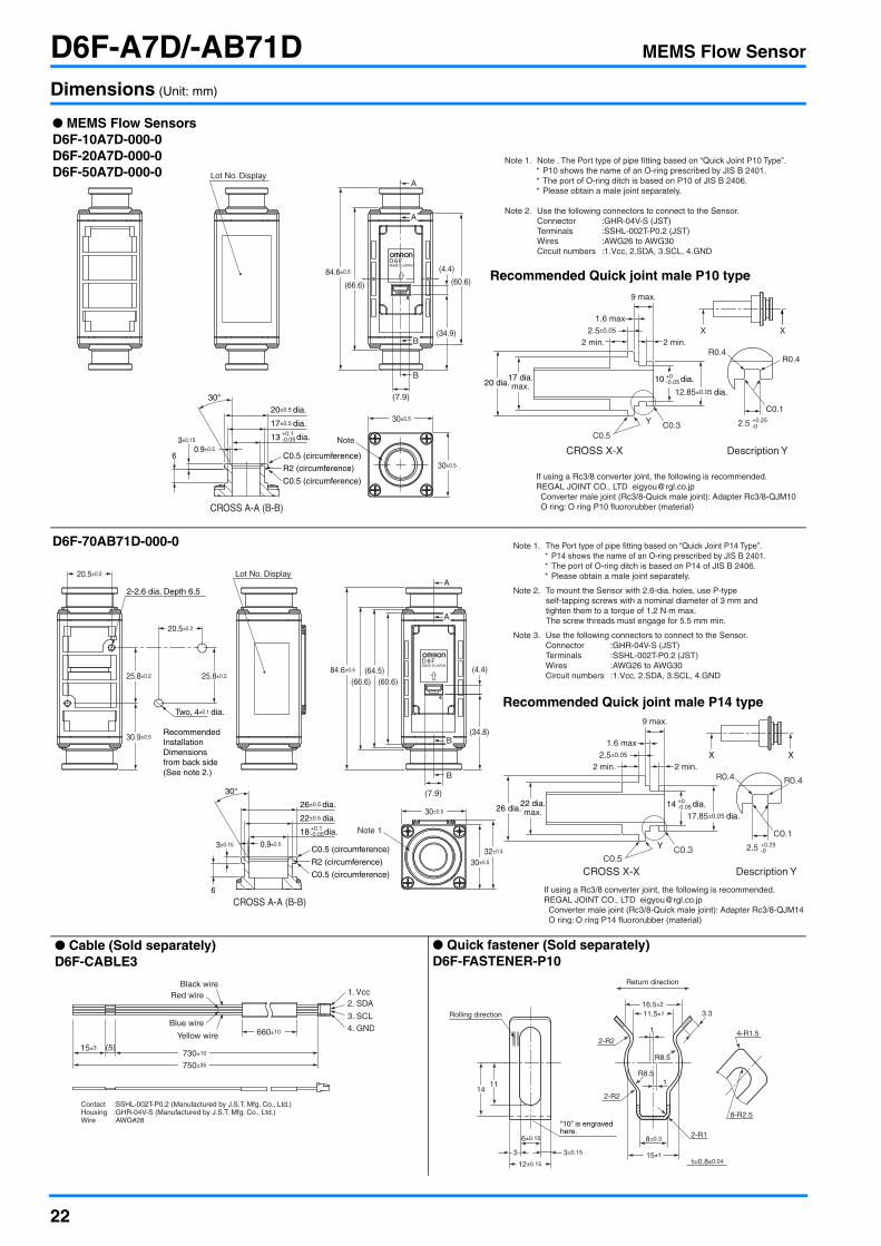
Dimensions (Unit: mm)
B
B
(4.4)
(60.6)
(34.9)
(7.9)
A
A
84.6±0.5
17±0.5 dia.
20±0.5 dia.
(66.6)
30±0.5
30±0.5
Note
CROSS A-A (B-B)
13 dia.+0.1-0.05
0.9±0.56
3±0.15
30°
Note 1. Note . The Port type of pipe fitting based on “Quick Joint P10 Type”. * P10 shows the name of an O-ring prescribed by JIS B 2401. * The port of O-ring ditch is based on P10 of JIS B 2406. * Please obtain a male joint separately.
Note 2. Use the following connectors to connect to the Sensor. Connector :GHR-04V-S (JST) Terminals :SSHL-002T-P0.2 (JST) Wires :AWG26 to AWG30 Circuit numbers :1.Vcc, 2.SDA, 3.SCL, 4.GND
Lot No. Display
C0.5 (circumference)
C0.5 (circumference)
R2 (circumference)If using a Rc3/8 converter joint, the following is recommended.REGAL JOINT CO., LTD [email protected] Converter male joint (Rc3/8-Quick male joint): Adapter Rc3/8-QJM10 O ring: O ring P10 fluororubber (material)
9 max.
1.6 max2.5±0.05
2 min. 2 min.
C0.3C0.5
R0.4R0.4
C0.1
2.5 +0.25-0
CROSS X-X Description Y
Y
X X
12.85±0.05 dia.20 dia.
17 dia.max.
10 dia.+0-0.05
● MEMS Flow SensorsD6F-10A7D-000-0D6F-20A7D-000-0D6F-50A7D-000-0
Recommended Quick joint male P10 type
Note 1. The Port type of pipe fitting based on “Quick Joint P14 Type”. * P14 shows the name of an O-ring prescribed by JIS B 2401. * The port of O-ring ditch is based on P14 of JIS B 2406. * Please obtain a male joint separately.
Note 2. To mount the Sensor with 2.6-dia. holes, use P-type self-tapping screws with a nominal diameter of 3 mm and tighten them to a torque of 1.2 N·m max. The screw threads must engage for 5.5 mm min.
Note 3. Use the following connectors to connect to the Sensor. Connector :GHR-04V-S (JST) Terminals :SSHL-002T-P0.2 (JST) Wires :AWG26 to AWG30 Circuit numbers :1.Vcc, 2.SDA, 3.SCL, 4.GND
B
B
(4.4)
(34.8)
(7.9)
A
A
25.8±0.2
30.9±0.5
84.6±0.5 (64.5)(66.6) (60.6)
30±0.5
20.5±0.2
20.5±0.2
25.8±0.2
30±0.5
32±0.5
Note 1
Lot No. Display
2-2.6 dia. Depth 6.5
CROSS A-A (B-B)
22±0.5 dia.
26±0.5 dia.
18 dia.+0.1-0.05
0.9±0.5
6
3±0.15
30°
Two, 4±0.1 dia.
Recommended Installation Dimensionsfrom back side (See note 2.)
C0.5 (circumference)
C0.5 (circumference)
R2 (circumference)C0.3
C0.5
R0.4 R0.4
C0.1Y
X X
If using a Rc3/8 converter joint, the following is recommended.REGAL JOINT CO., LTD [email protected] Converter male joint (Rc3/8-Quick male joint): Adapter Rc3/8-QJM14 O ring: O ring P14 fluororubber (material)
9 max.
1.6 max2.5±0.05
2 min. 2 min.
2.5 +0.25-0
CROSS X-X Description Y
17.85±0.05 dia.26 dia.
22 dia.max.
14 dia.+0-0.05
D6F-70AB71D-000-0
Recommended Quick joint male P14 type
● Cable (Sold separately)D6F-CABLE3
● Quick fastener (Sold separately)D6F-FASTENER-P10
1. Vcc2. SDA
3. SCL
4. GND660±10
730±1015±3 (5)
750±35
Contact :SSHL-002T-P0.2 (Manufactured by J.S.T. Mfg. Co., Ltd.)Housing :GHR-04V-S (Manufactured by J.S.T. Mfg. Co., Ltd.)Wire :AWG#28
Black wire
Yellow wire
Red wire
Blue wire
“10” is engraved here.
16.5±2
3.3
4-R1.5
8-R2.5
2-R1
t=0.8±0.04
2-R2
1R8.5
R8.5
11.5±1
15±13±0.15
1411
12±0.15
6±0.15
3
8±0.3
1
2-R2
Return direction
Rolling direction

23
D6F-AB71MEMS Flow Sensor
Reduction of Piping time by quick joint connection• Reduce the influence of pulsation flow by bypass flow path • 30 L/min and 70 L/min of Air can be measured.• Compact size of 30 × 84.6 × 32 mm (H × W × D).
Ordering InformationMEMS Flow Sensor
Accessory (Sold separately)
ConnectionsD6F-30AB71-000D6F-70AB71-000
Output Voltage Characteristics
D6F-30AB71-000
D6F-70AB71-000
Measurement conditions: Power-supply voltage 12±0.1 VDC, ambient temper-ature 25±5°C and ambient humidity 35 to 75%RH.
RoHS Compliant
Refer to the Common Precautions for the D6F Series on page 40.
Flow Port Type Applicable fluid Flow rate range Model
Quick joint P14 Air0 to 30 L/min D6F-30AB71-000
0 to 70 L/min D6F-70AB71-000
Type Model
Cable D6F-CABLE1
Enlarged View
3:GND2:Vout1:Vcc
Pin No. 1: Vcc2: Vout3: GND
Connector 53398-03** (Made by Molex Japan)
Use the following connectors for connections to the D6F:Housing 51021-0300 (Made by Molex Japan)Terminals 50079 (Made by Molex Japan)Wires AWG28 to AWG26
Flow rateL/min (normal) 0 6 12 18 24 30
Output voltageV
1.00±0.12
1.25±0.12
1.91±0.12
2.75±0.12
3.78±0.12
5.00±0.12
Flow rateL/min (normal) 0 14 28 42 56 70
Output voltageV
1.00±0.12
1.43±0.12
2.25±0.12
3.14±0.12
4.06±0.12
5.00±0.12
6.0
5.0
4.0
3.0
2.0
1.0
60 24 3018120.0
Flow rate (L/min)
Out
put v
olta
ge (
V)
6.0
5.0
4.0
3.0
2.0
1.0
140 56 7042280.0
Flow rate (L/min)
Out
put v
olta
ge (
V)
D6F-30AB71-000
D6F-70AB71-000

24
D6F-AB71 MEMS Flow Sensor
Characteristics/Performance
Note: 1. Volumetric flow rate at 0°C, 101.3 kPa.Note: 2. Dry gas (must not contain large particles, e.g., dust, oil, or mist.)Note: 3. Reference (typical)Note: 4. With no condensation or icing.
Dimensions (Unit: mm)
● Cable (Sold separately)D6F-CABLE1
Model D6F-30AB71-000 D6F-70AB71-000
Flow Range (See note 1.) 0 to 30 L/min 0 to 70 L/min
Calibration Gas (See note 2.) Air
Flow Port Type Quick joint P14
Electrical Connection Three-pin connector
Power Supply 10.8 to 26.4 VDC
Current Consumption 15 mA max. with no load and Vcc of 12 to 24 VDC, GND = 0 VDC, 25°C
Output Voltage 1 to 5 VDC (non-linear output, load resistance of 10 kΩ min.)
Accuracy ±3%F.S. (25°C characteristic)
Repeatability (See note 3.) ±0.3%F.S.
Output Voltage (Max.) 5.7 VDC (Load resistance: 10 kΩ)
Output Voltage (Min.) 0 VDC (Load resistance: 10 kΩ)
Rated Power Supply Voltage 26.4 VDC
Rated Output Voltage 6 VDC
Case PPS
Degree of Protection IEC IP40 (Excluding tubing sections.)
Withstand Pressure 100 kPa
Pressure Drop (See note 3.) 0.88 kPa 3.49 kPa
Operating Temperature (See note 4.) –10 to +60°C
Operating Humidity (See note 4.) 35 to 85%RH
Storage Temperature (See note 4.) –30 to +80°C
Storage Humidity (See note 4.) 35 to 85%RH
Temperature Characteristics ±3%F.S. for 25°C characteristic at an ambient temperature of –10 to +60°C
Insulation Resistance Between sensor outer cover and lead terminals: 20 MΩ min. (at 500 VDC)
Dielectric Strength Between sensor outer cover and lead terminals: 500 VAC, 50/60 Hz min. for 1 min (leakage current: 1 mA max.)
Weight 75 g
C0.3C0.5
R0.4 R0.4
C0.1Y
X X
20.5
25.8
30.9
2-2.6 dia Depth 6.5 (See note 2.)
Lot No. Display
If using a Rc3/8 converter joint, the following is recommended.REGAL JOINT CO., LTD [email protected] Converter male joint (Rc3/8-Quick male joint): Adapter Rc3/8-QJM14 O ring: O ring P14 fluororubber (material)
9 max.
1.6 max2.5±0.05
2 min. 2 min.
2.5 +0.25-0
CROSS X-X Description Y
17.85±0.05 dia.26 dia.
22 dia.max.
(60.6)(64.5)
(66.6)84.6
(6)
(3.7)
(33.4)
30 32
30
A
A
B
See note 1.
Note 1. The flow path inlet and outlet ports conform to P14-type female quick-connect joints. (The tube inlet and outlet ports have the same shape.)* P14 is the number of an O-ring specified in JIS B 2401.* The O-ring groove in the male joint must conform to P14 in JIS B 2406.
* Please obtain a male joint separately.Note 2. To mount the Sensor with 2.6-dia. holes, use P-type self-tapping screws with
a nominal diameter of 3 mm and tighten them to a torque of 1.2 N·m max.The screw threads must engage for 5.5 mm min.
Note 3: Use the following connectors to connect to the Sensor.Connector : GHR-04V-S (JST)Terminals : SSHL-002T-P0.2 (JST)Wires : AWG26 to AWG30Circuit numbers : 1. Vcc, 2. SDA, 3. SCL, and 4. GND.
C0.5 (circumference)
C0.5 (circumference)
R2 (circumference)
6
3±0.15
30°26 dia.
0.9
22 dia.
18 dia.+0.1-0.05
CROSS A-A
14 dia.+0-0.05
● MEMS Flow SensorsD6F-30AB71-000D6F-70AB71-000
Recommended Quick joint male P14 type
1. Vcc
2. Vout
Brown wireBlack wire
100±15
200±35
Blue wire 3. GND
Connector :51021 (Manufactured by Molex, LLC)Terminal :50079 (Manufactured by Molex, LLC)Wire :0.14SQ
25
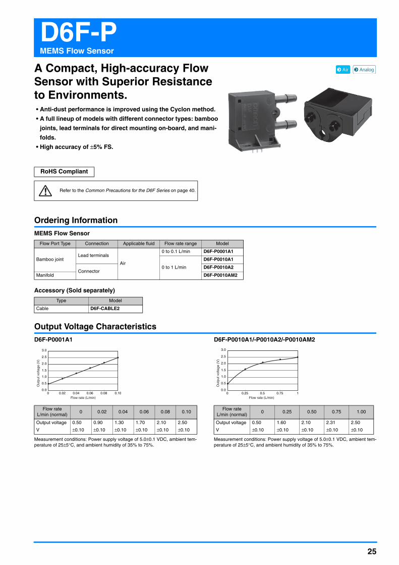
D6F-PMEMS Flow Sensor
A Compact, High-accuracy Flow Sensor with Superior Resistance to Environments.• Anti-dust performance is improved using the Cyclon method.
• A full lineup of models with different connector types: bamboo
joints, lead terminals for direct mounting on-board, and mani-
folds.
• High accuracy of ±5% FS.
Ordering InformationMEMS Flow Sensor
Accessory (Sold separately)
Output Voltage CharacteristicsD6F-P0001A1
Measurement conditions: Power supply voltage of 5.0±0.1 VDC, ambient tem-perature of 25±5°C, and ambient humidity of 35% to 75%.
D6F-P0010A1/-P0010A2/-P0010AM2
Measurement conditions: Power supply voltage of 5.0±0.1 VDC, ambient tem-perature of 25±5°C, and ambient humidity of 35% to 75%.
RoHS Compliant
Refer to the Common Precautions for the D6F Series on page 40.
Flow Port Type Connection Applicable fluid Flow rate range Model
Bamboo jointLead terminals
Air
0 to 0.1 L/min D6F-P0001A1
0 to 1 L/min
D6F-P0010A1
ConnectorD6F-P0010A2
Manifold D6F-P0010AM2
Type Model
Cable D6F-CABLE2
Flow rate L/min (normal)
0 0.02 0.04 0.06 0.08 0.10
Output voltage
V
0.50
±0.10
0.90
±0.10
1.30
±0.10
1.70
±0.10
2.10
±0.10
2.50
±0.10
3.0
2.5
2.0
1.5
1.0
0.5
0.00.02 0.04 0.06 0.08 0.100
Out
put v
olta
ge (
V)
Flow rate (L/min)
Flow rate L/min (normal)
0 0.25 0.50 0.75 1.00
Output voltage
V
0.50
±0.10
1.60
±0.10
2.10
±0.10
2.31
±0.10
2.50
±0.10
3.0
2.5
2.0
1.5
1.0
0.5
0.00.25 0.5 0.75 10
Out
put v
olta
ge (
V)
Flow rate (L/min)

26
D6F-P MEMS Flow Sensor
Characteristics/Performance
Note: 1. Volumetric flow rate at 0°C, 101.3 kPa.Note: 2. Dry gas. (must not contain large particles, e.g., dust, oil, or mist.)Note: 3. Reference (typical)Note: 4. With no condensation or icing.
TubingYou can measure large flows by mounting the Sensor on a bypass.
Model D6F-P0001A1 D6F-P0010A1 D6F-P0010A2 D6F-P0010AM2
Flow Range (See note 1.) 0 to 0.1 L/min 0 to 1 L/min
Calibration Gas (See note 2.) Air
Flow Port TypeBamboo joint
Maximum outside diameter: 4.9 mm, minimum outside diameter: 4.0 mmManifold
Electrical Connection Lead terminals Three-pin connector
Power Supply 4.75 to 5.25 VDC
Current Consumption 15 mA max. with no load and a Vcc of 5.0 V
Output Voltage 0.5 to 2.5 VDC (Load resistance: 10 kΩ)
Accuracy ±5% FS (25°C characteristic)
Repeatability (See note 3.) ±1.0% FS ±0.4% FS
Output Voltage (Max.) 3.1 VDC (Load resistance: 10 kΩ)
Output Voltage (Min.) 0 VDC (Load resistance: 10 kΩ)
Rated Power Supply Voltage 10 VDC
Rated Output Voltage 4 VDC
Case PBT
Degree of Protection IEC IP40 (Excluding tubing sections.)
Withstand Pressure (See note 3.) 50 kPa
Pressure Drop (See note 3.) 0.005 kPa 0.19 kPa 0.67 kPa
Operating Temperature (See note 4.) −10 to +60°C
Operating Humidity (See note 4.) 35% to 85%
Storage Temperature (See note 4.) −40 to +80°C
Storage Humidity (See note 4.) 35% to 85%
Temperature Characteristics ±5% FS for 25°C characteristic at an ambient temperature of -10 to +60°C
Insulation Resistance Between Sensor outer cover and lead terminals: 20 MΩ min. (at 500 VDC)
Dielectric Strength Between Sensor outer cover and lead terminals: 500 VAC, 50/60 Hz min. for 1 min (leakage current: 1 mA max.)
Weight 8.5 g 8.0 g
P1
Resistance to flow
Mounting DirectionBamboo joint Sensor Manifold-type Sensor
D6F-P Flow Sensor
P2
27
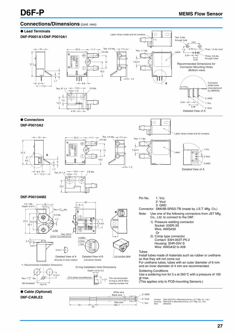
D6F-P MEMS Flow Sensor
Connections/Dimensions (Unit: mm)
D6F
MADE IN JAPAN
2.6 dia.23.3 11.7 Two, 4.9 dia.
1.2
2.8 dia.Two, R: 1.41.5
17.2
Two, 1.1 dia.Label
A
Recommended Dimensions for Connector Mounting Holes
(Bottom view)
Label: Gives model and lot numbers.
27.2
1.7
6
6
16.2
14 7.6±0.2
13.27.2
2.54
5.08
Detailed View of A
Connector XG8V-0344 (manufactured by OMRON)
2. Vout
1. Vcc
3. GND
5.04
2.54
Two, 3-dia. through hole
13.5
Three, 1.3-dia. lands
Three, 0.8-dia. through holes
4.767.210
9.8
7.3
13.5
4.76
● Lead Terminals
D6F-P0001A1/D6F-P0010A1
D6F
MADE IN JAPAN
Detailed View of A
A
1.Vcc
2.Vout
3.GND
2.6 dia.23.3 11.7 Two, 4.9 dia.
1.2
2.8 dia.Two, R: 1.41.517.2
Two, 1.1 dia.
Label
Label: Gives model and lot numbers.
27.2
1.7
6
8.5
8.5 16.2
14 7.6±0.2
13.2
10 7.3
13.5
● Connectors
D6F-P0010A2
D6F-P0010AM2
0.3±0.1
Lot number label
Two, C0.3 (entire circumference)
C0.4 (entire circumference) The recommended O-ring is JIS B 2401, nominal number P4.
2-R6
1±0.1 dia.,Depth: 2.4±0.1
Depth: 2.6 to 3.0
Detailed View of AGrooves to stop rotation
O-ring Installation Hole Dimensions
Detailed View of BConnector Details
27.2
22.114±0.05
2.7±0.1
0.3±0.1
6.7±0.1 *118
228
6
2
6.4 9.6
7 +0.5 0
A
B
3.GND2.Vout1.Vcc
14±0.05M3 threaded
Two, 7 dia.+0.5 0
*1. Recommended Installation Dimensions
6.7±0.1
Two, 4 dia. 0−0.05
3.5 dia.
1+0.1 0
Pin No. 1: Vcc2: Vout3: GND
Connector SM03B-SRSS-TB (made by J.S.T. Mfg. Co.)
Note: Use one of the following connectors from JST Mfg.Co., Ltd. to connect to the D6F.
1) Pressure welding connectorSocket: 03SR-3SWire: AWG#30Or
2) Crimp type connectorContact: SSH-003T-P0.2Housing: SHR-03V-SWire: AWG#32 to #28
TubesInstall tubes made of materials such as rubber or urethane so that they will not come out.For urethane tubes, tubes with an outer diameter of 6 mm and an inner diameter of 4 mm are recommended.
Soldering ConditionsUse a soldering iron for 5 s at 350°C with a pressure of 100 gf max.(This applies only to PCB-mounting Sensors.)
15±3(5)
180±10
3: GND
2: Vout
White wireBlack wire
Red wire 1: Vcc
Contact :SSH-003T-P0.2 (Manufactured by J.S.T. Mfg. Co., Ltd.)Housing :SHR-03V-S (Manufactured by J.S.T. Mfg. Co., Ltd.)Wire :AWG#30
● Cable (Optional)
D6F-CABLE2

28
D6F-PHMEMS Differential pressure Sensor
A Compact, High-accuracy DifferentialPressure Sensor with Superior Resistance to Environments.• High accuracy of ±3% RD
• Linearized and temperature compensated
• Digital output (I2C communication)
• High flow impedance to reduce the influence of bypass configuration
• Lineup of 4 types of slave address models
Ordering Information
Output CharacteristicsD6F-PH0025AD1-@
Measurement conditions: Power supply voltage of 3.3 ±0.1 VDC, ambient tem-perature of 25±5°C, and ambient humidity of 35% to 75%.Differential pressure conversion formula: Dp = (Op - 1024) / 60000 × 250Dp = Differential pressure, Op = Output
D6F-PH0505AD3-@
Measurement conditions: Power supply voltage of 3.3 ±0.1 VDC, ambient tem-perature of 25±5°C, and ambient humidity of 35% to 75%.Differential pressure conversion formula: Dp = (Op - 1024) / 60000 × 100 - 50Dp = Differential pressure, Op = Output
D6F-PH5050AD3-@
Measurement conditions: Power supply voltage of 3.3 ±0.1 VDC, ambient tem-perature of 25±5°C, and ambient humidity of 35% to 75%.Differential pressure conversion formula: Dp = (Op - 1024) / 60000 × 1000 - 500Dp = Differential pressure, Op = Output
Note. Change of gas density affects the sensor output.Change of atmospheric pressure is compensated by the following formula.Dpeff = Dp × (Pstd / Pamb)Dpeff: Effective differential pressureDp: Differential pressure of the sensor outputPstd: Standard atmospheric pressure (1013.25 hPa)Pamb: Actual ambient atmospheric pressure (hPa)
RoHS Compliant
Refer to the Common Precautions for the D6F Series on page 40.
Applicable fluid (See note 1.) Measurement range (See note 3.) slave address (7 bit) Model
Air (See note 2.)
0 to 250 Pa
0b110_1100, 0x6C D6F-PH0025AD10b110_1101, 0x6D D6F-PH0025AD1-10b110_1110, 0x6E D6F-PH0025AD1-20b110_1111, 0x6F D6F-PH0025AD1-3
-50 to 50 Pa
0b110_1100, 0x6C D6F-PH0505AD30b110_1101, 0x6D D6F-PH0505AD3-10b110_1110, 0x6E D6F-PH0505AD3-20b110_1111, 0x6F D6F-PH0505AD3-3
-500 to 500 Pa
0b110_1100, 0x6C D6F-PH5050AD30b110_1101, 0x6D D6F-PH5050AD3-10b110_1110, 0x6E D6F-PH5050AD3-20b110_1111, 0x6F D6F-PH5050AD3-3
Note: 1. The Sensor be calibrated for differ-ent gas types. Consult your Omronrepresentative.
Note: 2. Dry gas must not contain large par-ticles, e.g., dust, oil, or mist.
Note: 3. At standard atmospheric pressure(1013.25 hPa)
Differential pressure (Pa) 0 50 100 150 200 250
Output(HEX)
1024(0400)
13024(32E0)
25024(61C0)
37024(90A0)
49024(BF80)
61024(EE60)
Differential pressure (Pa)
70000
60000
50000
40000
30000
20000
100000
Out
put (
coun
t)
50 100 150 200 2500
Differential pressure (Pa) -50 -30 -10 0 10 30 50
Output(HEX)
1024(0400)
13024(32E0)
25024(61C0)
31024(7930)
37024(90A0)
49024(BF80)
61024(EE60)
Differential pressure (Pa)
70000
60000
50000
40000
30000
20000
100000
Out
put (
coun
t)
-30 -10 10 30 50-50
Differential pressure (Pa) -500 -300 -100 0 100 300 500
Output(HEX)
1024(0400)
13024(32E0)
25024(61C0)
31024(7930)
37024(90A0)
49024(BF80)
61024(EE60)
Differential pressure (Pa)
70000
60000
50000
40000
30000
20000
100000
Out
put (
coun
t)
-300 -100 100 300 500-500

29
D6F-PH MEMS Differential pressure Sensor
Characteristics/Performance
Note: 1. At standard atmospheric pressure (1013.25 hPa)Note: 2. Dry gas must not contain large particles, e.g., dust, oil, or mist.Note: 3. The zero point tolerance and span tolerance are independent uncertainties and add according to the principles of error propagation.Note: 4. With no condensation or icing.Note: 5. Type D6F-PH is based on thermal flow principle. Air flow is needed to measure the differential pressure.
Typical characteristic of air flow by differential pressure is below.
Relation between pressure and flow rate
Model D6F-PH0025AD1-@ D6F-PH0505AD3-@ D6F-PH5050AD3-@
Differential pressure range (See note 1) 0 to 250 Pa ±50 Pa ±500 Pa
Calibration Gas (See note 2.) Air
Port Type Bamboo joint, Maximum outside diameter: 4.9 mm, minimum outside diameter: 4.0 mm
Power Supply 2.3 to 3.6 VDC
Current Consumption 6 mA max. with no load and Vcc of 3.3 VDC, GND = 0 VDC, 25°C
Resolution 12 bit
Zero point tolerance (See note 3.) ±0.2 Pa
Span tolerance (See note 3.) ±3% RD
Span shift due to temperature variation < 0.5% RD per 10°C
Response time33 ms typical at 12 bit resolution (50 ms max.)
The processing time is 6 ms typical at 12 bit resolution.
Gas flow through sensor (See note 5.) 63 mL/min 23 mL/min 100 mL/min
Interface I2C
Case material PPS
Degree of Protection IEC IP40 (Excluding tubing sections.)
Withstand Pressure 10 kPa
Operating temperature (See note 4.) -20 to +80°C
Operating humidity (See note 4.) 35 to 85 %RH
Storage temperature (See note 4.) -40 to +80°C
Storage humidity (See note 4.) 35 to 85 %RH
Insulation Resistance Between Sensor outer cover and lead terminals: 20 MΩ min. (at 500 VDC)
Dielectric Strength Between Sensor outer cover and lead terminals: 500 VAC, 50/60 Hz min. for 1 min (leakage current: 1 mA max.)
Weight 5.2 g
Differential pressure (Pa)
60
40
20
0
-20
-40
-60
Flo
w r
ate
(mL/
min
)
-300 -100 100 300 500-500

30
D6F-PH MEMS Differential pressure Sensor
Connections/Dimensions (Unit: mm)
Electrical connection
Communication
D6F-PH0025AD1D6F-PH0505AD3D6F-PH5050AD3
D6F-PH0025AD1-1D6F-PH0505AD3-1D6F-PH5050AD3-1
D6F-PH0025AD1-2D6F-PH0505AD3-2D6F-PH5050AD3-2
D6F-PH0025AD1-3D6F-PH0505AD3-3D6F-PH5050AD3-3
Serial Interface I2C
Master/SlaveHEX 0x6C 0x6D 0x6E 0x6F
BIN (7bit) 0b110_1100 0b110_1101 0b110_1110 0b110_1111
Speed mode Max. 400kHz (Fast Mode)
SignalSCL Serial Clock
SDA Data Signal
Four, through hole 0.8 dia.
Three, 2
Two, 4 dia.
Two, R2
Two, through hole 2 dia.
Two, through hole 2.2 dia
Recommendation size for pin header installation(tolerrances: ±0.1)
Pin Header
1.23.1
2:GND
4:SCL
1:SDA
3:VCC
7.2
12 10.56.5
5
4
10
22
Four, 0.48 dia.3.7
Two, 4.9 dia
Two, 4 dia.
3.37
16.5
Three, 25.25
Two, through hole 2 dia
26 20 10 16.5
187.05
Low pressure side
High pressure side
TubesInstall tubes made of materials such as rubber, urethane or nylon so that they will not come out.For urethane tubes, tubes with an outer diameter of 6 mm and an inner diameter of 4 mm are recommended.
Soldering ConditionsUse a soldering iron for 5 s at 350°C with a pressure of 100 gf max.
Mounting DirectionInstall the Sensor so that the joints are facing upward.
Sensor(slave) Master
SCL
pull-up resister 2.2 kΩ
pull-up resister 2.2 kΩ
Vcc 3.3 V
Vcc
Vcc
GND
SDA

31
D6F-WMEMS Flow Sensor
A Compact Sensor That Uses OMRON’s Unique Flow Path Structure for High-performance Flow Rate Measurement.• Anti-dust performance enhanced by OMRON’s unique three-dimensional
flow path structure.• High accuracy of ±5% FS.
Ordering InformationMEMS Flow Sensor
Accessory (Sold separately)
Connections
Output Voltage Characteristics
D6F-W01A1
D6F-W04A1
The flow velocity is the value calculated from the mass flow rate in OMRON’s specified48-mm-dia. wind tunnel. It does not indicate the flow velocity determined by the Mea-surement Law of Japan. The wind tunnel conditions are shown in Figure 1, below.
Measurement conditions: Power supply voltage of 12 VDC, ambient tempera-ture of 25°C, and ambient humidity of 35% to 75%.
D6F-W10A1
The flow velocity is the value calculated from the mass flow rate in OMRON’s specified155-mm-dia. wind tunnel. It does not indicate the flow velocity determined by the Mea-surement Law of Japan. The wind tunnel conditions are shown in Figure 2, below.
Measurement conditions: Power supply voltage of 12 VDC and ambient temper-ature of 25°C
RoHS Compliant
Refer to the Common Precautions for the D6F Series on page 40.
Applicable fluid Flow rate range Model
Air
0 to 1 m/s D6F-W01A1
0 to 4 m/s D6F-W04A1
0 to 10 m/s D6F-W10A1
Type Model
Cable D6F-W CABLE
Enlarged View
2. Vout. 3. GND.
1. Vcc.
Pin No. 1: Vcc2: Vout3: GND
Connector S3B-ZR-SM2-TF (made by J.S.T. Mfg. Co.)
D6F-W01A1D6F-W04A1D6F-W10A1
Use the following connectors from J.S.T. Mfg. Co. Ltd. to connect the D6F:
Housing: ZHR-3
Contacts: SZH-002T-P0.5Wires: AWG28 to AWG26
OrContacts: SZH-003T-P0.5Wires: AWG32 to AWG28
Flow velocitym/s
0 0.25 0.50 0.75 1.00
Output voltage V 1.00±0.2 1.35±0.2 2.01±0.2 3.27±0.2 5.00±0.2
Flow velocitym/s
0 1.0 2.0 3.0 4.0
Output voltage V 1.00±0.2 1.58±0.2 2.88±0.2 4.11±0.2 5.00±0.2
Flow velocitym/s
0 2.0 4.0 6.0 8.0 10.0
Output voltage V 1.00±0.24 1.94±0.24 3.23±0.24 4.25±0.24 4.73±0.24 5.00±0.24
6.0
5.0
4.0
3.0
2.0
1.0
0.250.00 1.000.750.500.0
Out
put v
olta
ge (
V)
Flow velocity (m/s)1.00.0 4.03.02.0
6.0
5.0
4.0
3.0
2.0
1.0
0.0
Out
put v
olta
ge (
V)
Flow velocity (m/s)
6.0
5.0
4.0
3.0
2.0
1.0
0.00 2 4 6 8 10
Out
put v
olta
ge (
V)
Flow velocity (m/s)
D6F-W01A1 D6F-W04A1
D6F-W10A1
48 dia.
60 20.8
Air volume sensor
Flow velocity measurement position Figure 1: Wind Tunnel
100 10
18
155 dia.
Honeycomb flow grate Air volume sensor
Flow velocity measurement position
Figure 2: Wind Tunnel

32
D6F-W MEMS Flow Sensor
Characteristics/Performance
Note: 1. Volumetric flow rate at 25°C, 101.3 kPa.Note: 2. Dry gas. (must not contain large particles, e.g., dust, oil, or mist.)Note: 3. Reference (typical)Note: 4. With no condensation or icing.
Dimensions (Unit: mm)
● Cable (Optional)
D6F-W CABLE
Model D6F-W01A1 D6F-W04A1 D6F-W10A1
Flow Range (See note 1.) 0 to 1 m/s 0 to 4 m/s 0 to 10 m/s
Calibration Gas (See note 2.) Air
Electrical Connection Three-pin connector
Power Supply 10.8 to 26.4 VDC
Current Consumption 15 mA max. with no load, with a Vcc of 12 to 24 VDC, and at 25°C
Output Voltage 1 to 5 VDC (non-linear output, load resistance of 10 kΩ)
Accuracy ±5% FS (25°C characteristic) ±6% FS (25°C characteristic)
Repeatability (See note 3.) ±0.4% FS
Output Voltage (Max.) 5.7 VDC (Load resistance: 10 kΩ)
Output Voltage (Min.) 0 VDC (Load resistance: 10 kΩ)
Rated Power Supply Voltage 26.4 VDC
Rated Output Voltage 6 VDC
Case PPS
Degree of Protection IEC IP40 (except for flow inlet and outlet)
Operating Temperature (See note 4.) −10 to 60°C
Operating Humidity (See note 4.) 35% to 85%
Storage Temperature (See note 4.) −40 to 80°C
Storage Humidity (See note 4.) 35% to 85%
Temperature Characteristics ±5% FS for 25°C characteristic at an ambient temperature of −10 to 60°C
Insulation Resistance Between Sensor outer cover and lead terminals: 20 MΩ min. (at 500 VDC)
Dielectric Strength Between Sensor outer cover and lead terminals: 500 VAC, 50/60 Hz min. for 1 min (leakage current: 1 mA max.)
Weight 6.3 g
MADE IN JAPAN
4.2±0.2
3.2±0.2
Two, R: 1.6
30.5±0.2
19.5
2 dia., Depth: 2.5
3.2 ±0.2 dia.4
5
Flow inlet
1.2 2.6
9
20 8 R4
R4
8
24 39
7
Flow outlet
Flow outlet
1.2 2.6 Two, M3 screws
Lot number label
30.5±0.055
Mounting Hole Dimensions
● MEMS Flow Sensors
D6F-W01A1D6F-W04A1D6F-W10A1
5±1
15±3 30±10
GND: Blue
Vout: Black
Vcc: Brown50±10100±10
Contact :SZH-002T-P0.5 (Manufactured by J.S.T. Mfg. Co., Ltd.)Housing :ZHR-3 (Manufactured by J.S.T. Mfg. Co., Ltd.)Wire :AWG#26
33
D6F-VMEMS Flow Sensor
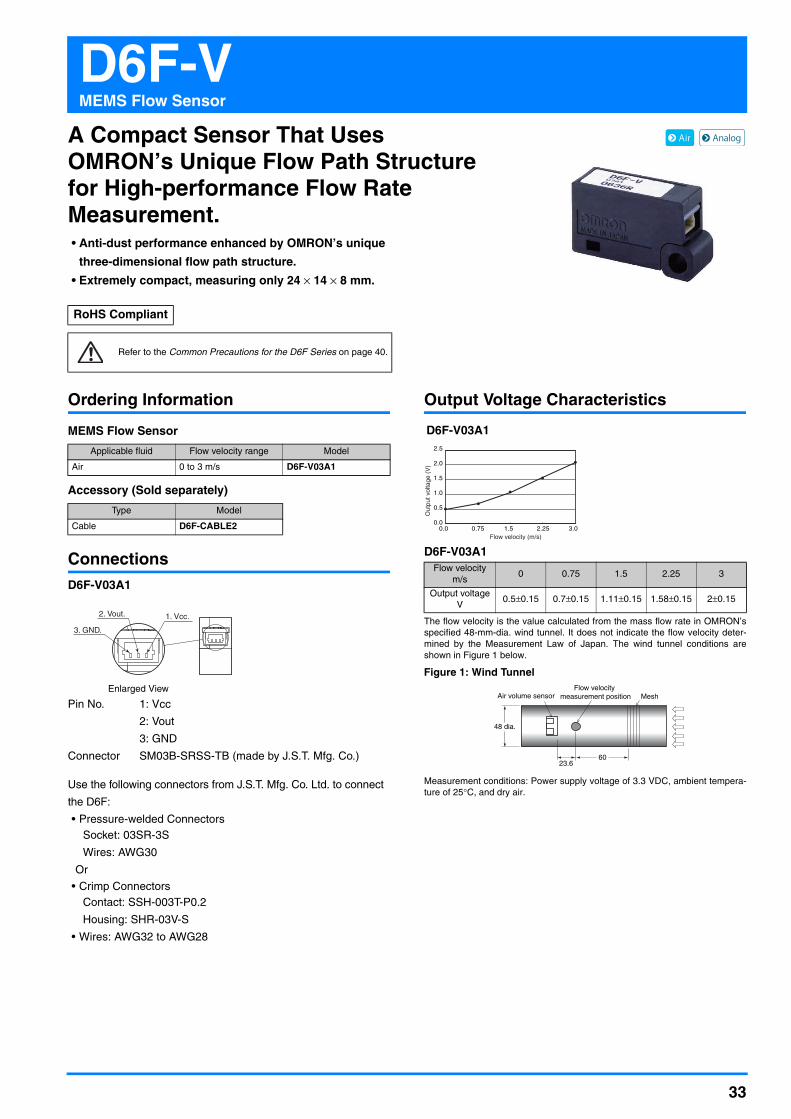
A Compact Sensor That Uses OMRON’s Unique Flow Path Structure for High-performance Flow Rate Measurement.• Anti-dust performance enhanced by OMRON’s unique
three-dimensional flow path structure.
• Extremely compact, measuring only 24 × 14 × 8 mm.
Ordering Information
MEMS Flow Sensor
Accessory (Sold separately)
ConnectionsD6F-V03A1
Pin No. 1: Vcc
2: Vout
3: GND
Connector SM03B-SRSS-TB (made by J.S.T. Mfg. Co.)
Use the following connectors from J.S.T. Mfg. Co. Ltd. to connect
the D6F:
• Pressure-welded ConnectorsSocket: 03SR-3S
Wires: AWG30
Or
• Crimp ConnectorsContact: SSH-003T-P0.2
Housing: SHR-03V-S
• Wires: AWG32 to AWG28
Output Voltage Characteristics
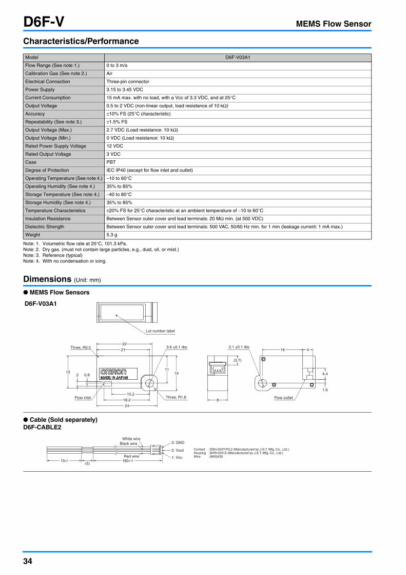
D6F-V03A1
The flow velocity is the value calculated from the mass flow rate in OMRON’sspecified 48-mm-dia. wind tunnel. It does not indicate the flow velocity deter-mined by the Measurement Law of Japan. The wind tunnel conditions areshown in Figure 1 below.
Measurement conditions: Power supply voltage of 3.3 VDC, ambient tempera-ture of 25°C, and dry air.
RoHS Compliant
Refer to the Common Precautions for the D6F Series on page 40.
Applicable fluid Flow velocity range Model
Air 0 to 3 m/s D6F-V03A1
Type Model
Cable D6F-CABLE2
Enlarged View
2. Vout. 1. Vcc.
3. GND.
Flow velocity m/s
0 0.75 1.5 2.25 3
Output voltage V
0.5±0.15 0.7±0.15 1.11±0.15 1.58±0.15 2±0.15
2.5
2.0
1.5
1.0
0.5
0.750.0 3.02.251.50.0
Out
put v
olta
ge (
V)
Flow velocity (m/s)
D6F-V03A1
60 23.6
48 dia.
Mesh Air volume sensor Flow velocity
measurement position
Figure 1: Wind Tunnel
34
D6F-V MEMS Flow Sensor
Characteristics/Performance
Note: 1. Volumetric flow rate at 25°C, 101.3 kPa.Note: 2. Dry gas. (must not contain large particles, e.g., dust, oil, or mist.)Note: 3. Reference (typical)Note: 4. With no condensation or icing.
Dimensions (Unit: mm)
● MEMS Flow Sensors
● Cable (Sold separately)D6F-CABLE2
Model D6F-V03A1
Flow Range (See note 1.) 0 to 3 m/s
Calibration Gas (See note 2.) Air
Electrical Connection Three-pin connector
Power Supply 3.15 to 3.45 VDC
Current Consumption 15 mA max. with no load, with a Vcc of 3.3 VDC, and at 25°C
Output Voltage 0.5 to 2 VDC (non-linear output, load resistance of 10 kΩ)
Accuracy ±10% FS (25°C characteristic)
Repeatability (See note 3.) ±1.5% FS
Output Voltage (Max.) 2.7 VDC (Load resistance: 10 kΩ)
Output Voltage (Min.) 0 VDC (Load resistance: 10 kΩ)
Rated Power Supply Voltage 12 VDC
Rated Output Voltage 3 VDC
Case PBT
Degree of Protection IEC IP40 (except for flow inlet and outlet)
Operating Temperature (See note 4.) −10 to 60°C
Operating Humidity (See note 4.) 35% to 85%
Storage Temperature (See note 4.) −40 to 80°C
Storage Humidity (See note 4.) 35% to 85%
Temperature Characteristics ±20% FS for 25°C characteristic at an ambient temperature of −10 to 60°C
Insulation Resistance Between Sensor outer cover and lead terminals: 20 MΩ min. (at 500 VDC)
Dielectric Strength Between Sensor outer cover and lead terminals: 500 VAC, 50/60 Hz min. for 1 min (leakage current: 1 mA max.)
Weight 5.3 g
11
21
15.2
18.2
0.8 13
Three, R1.8
24
14
22 Three, R0.5
2
3.6 ±0.1 dia.
Flow inlet 8
(3.7)
1.6
16
4.4
4 3.1 ±0.1 dia.
Flow outlet
Lot number label
D6F-V03A1
15±3(5)
180±10
3: GND
2: Vout
White wireBlack wire
Red wire 1: Vcc
Contact :SSH-003T-P0.2 (Manufactured by J.S.T. Mfg. Co., Ltd.)Housing :SHR-03V-S (Manufactured by J.S.T. Mfg. Co., Ltd.)Wire :AWG#30

35
D6F-DMEMS 2-Axis Flow Sensor
Save energy with airflow sensing. Optimize air conditioning control without sacrificing quality.• Two-axis sensing to detect not only the airflow speed but also the
airflow direction.
• Link up to 32 Sensors to achieve visualization over a wide range.
• Compact package for greater installation flexibility.
Ordering Information
Note: Dry gas must not contain large particles, eg dust, oil, mist.
Characteristics/PerformanceCharacteristics
Note: With no condensation or icing.
Performance
Note: 1. Flow velocity is determined by our standard wind tunnel (300 mm square), and this does not indicate the flow velocity specified in Measurement law. (Fig.1 shows our standard wind tunnel)
Fig. 1. Wind Tunnel
RoHS Compliant
Refer to the Safety Precautions on page 39 and Common Precautions for the D6F Series on page 40.
Applicable Medium Flow Range Model
Air (See note.) ±1.0m/s D6F-D010A32-00
Item Rating
Power-supply Voltage 4.5 to 5.5 VDC
Storage Temperature -10 to 55°C (without freezing and condensation)
Operating Temperature 0 to 40°C
Storage Humidity 30 to 85%
Operating Humidity 30 to 80%
Item Characteristic
Flow VelocityRange ±1.0m/s in each axis
Accuracy ±3%F.S. in each axis
Flow DirectionRange 0 to 360°
Accuracy ±15° (at 0.3m/s)
2500(Unit: mm)
2-Axis Flow Sensor
Flow velocity measurement point
200
Laminar ElementLaminar element
200 300300300
@300
Fan

36
D6F-D MEMS 2-Axis Flow Sensor
ConnectionFig. 2. Block Diagram
The sensor has two port of RJ-45 connectors (8 pins), and all the pair of each pin is connected internally.
These connectors can be used for daisy chain wiring when using multiple devices on the same bus (multi-drop connection).
The standard CAT5e straight LAN cable can be used for the electrical connection.
Interface
* The communication settings of this device can be set by DIP switch configuration as shown in Fig. 3. All bits are switched off before shipment.
Item Specifications
Interface RS-485
Wire Connection Multi-drop connection with daisy chain wiring (32 devices max.)
Communication system 2 wires : Half duplex
Baud rate 9600bps or 38400bps : DIP switch* selectable
Protocol Modbus-RTU
Transmission code Binary
Data length 8 bit
Stop bit 1 bit
Parity None
Response time 250 ms max.
Command interval 10 ms min. (Minimum wait time after receiving the response from the device to the consecutive command transmission)
Slave address 1 to 32 (0x01 to 0x20) : DIP switch* selectable
Termination resistor Built-in termination resistor : DIP switch* selectable
RS485Interface
MCUSensingElement
X-AxisFlow Sensor
Signal Processing
Y-AxisFlow Sensor
1. VCC2. GND3. NC4. TRD(−)5. TRD(+)6. NC7. GND8. VCC
RJ-45Connector
1. VCC2. GND3. NC4. TRD(−)5. TRD(+)6. NC7. GND8. VCC
Pin Symbol Function
1 VCC Power Supply Voltage
2 GND Ground
3 NC Non-Connection
4 TRD(-) Serial Interface
5 TRD(+) Serial Interface
6 NC Non-Connection
7 GND Ground
8 VCC Power Supply Voltage

37
D6F-D MEMS 2-Axis Flow Sensor
Fig. 3. DIP Switches
Fig. 4. Connection Example to Link Three Sensors
Fig. 4 shows an example of multi-drop connection when connecting three devices on the same bus.
In this case, slave address, baud rate and built-in termination resistor of each device must be set properly.
1
8
OFFON
Note: Slave address of the device = 1 + (5 bit of integer consisting of circuitnumber 1 to 5).
Circuits Function ON OFF
8 Built-in termination resistor Enable Disable
7 Baud rate 38400bps 9600bps
6 None - -
5 Slave Address : bit 4 1 0
4 Slave Address : bit 3 1 0
3 Slave Address : bit 2 1 0
2 Slave Address : bit 1 1 0
1 Slave Address : bit 0 1 0
SlaveAddress 0x01 Termination: Disable
SlaveAddress 0x02 Termination: Disable
SlaveAddress 0x03 Termination: Enable
Master

38
D6F-D MEMS 2-Axis Flow Sensor
Dimensions (Unit: mm)
D6F-D010A32-00
60 dia.
Y axis (+)
Y axis (−)
X axis (−)X axis (+)
LED DisplayGreen: Power IndicatorYellow: Lit when communication
* When using the fixing hole, Please do not exceed the depth (3.6 mm) of the shaded portion.
A
7
22
30
3.2
8
7
3.2
3 dia.Depth1.5
6.3 dia.
B
B
3.6
2.5
Cross B-B
Description A
34.7
Power switch Knob position LEFT: ON (default) Right: OFF
*

39
D6F-D MEMS 2-Axis Flow Sensor
Safety Precautions
The sensor is a precision device, and if large shock and load is
applied, it may cause a failure or characteristic change. Please
do not use the sensor which is added excessive shock to the ter-
minals, discompose the cover, or has fallen.
● Applicable medium and Device mounting
• Depending on the mounting position and the ambient environ-
ment, the foreign object such as dust can adhere to the inside
of the device and can cause clogging of the part of flow path.
As a result, the device may not perform as intended. And, the
characteristic specified in this document may not be main-
tained. Please use the device after enough ex-ante evaluation
under the condition of actual use in order to confirm the perfor-
mance and safety in the application.
• For the gasses other than the applicable medium, please use
the device in your responsibility after the confirmation of its
performance and safety.
However, do not use in the presence of inflammable gases,
such as hydrogen, methane, ethane, and a liquefied petroleum
gas. In addition, do not use with corrosive gases (such as chlo-
rine, sulfur, acid, alkali, ammonia etc.)
• The direction of the arrow on top of the body shows the posi-
tive direction of the device output in each axis. Please install
the device in a correct direction corresponding to the direction
of the flow. With the wrong installation, the device cannot mea-
sure flow direction correctly.
• After installation, the device may not perform as intended by
the presence of a flow obstacle around the device.
• After Installation, the device operation and its performance
should be checked before actual use in the application.
• Horizontal device orientation (top cover side up) is recom-
mended. If the device orientation is not horizontal, the output
may shift as an offset more than +/3%F.S.. For more details of
offset compensation features, please refer to the communica-
tion specification.
• The device may not operate properly, if a foreign object or a
flow obstacle is placed around the entrance of the flow path.
● Use environment
Please do not use the device in the following environments:
• Places where the device directly receives radiant heat from an
apparatus.
• Places where the device is exposed to water, salt water, water
droplets and oil splash.
• Places where the device is exposed to direct sunlight.
• Places with volatile gas, inflammable gas or corrosive gas
(such as chlorine, sulfur, acid, alkali, ammonia etc.)
• Places where frequent temperature changes.
• Places where dusty condition.
• Places with the possibility of freezing and dew condensation.
• Places where the device receives large magnitudes of vibra-
tion and shock.
• Places where the device receives strong electric field effect or
magnetic field effect.
● Noise Countermeasures
• Please check electrical noise condition before actual use. The
device may not perform as intended by the effect from electri-
cal noise.
• The voltage input that exceeds absolute maximum ratings
must not be applied. This can damage the electrical circuit of
the device. Place the protection circuit as needed, so that the
voltage to the lines will not exceed absolute maximum ratings.
• Take particular care to install away from AC power transform-
ers, live mains power lines and high power magnetic circuits.
• The device may not operate properly where the place with the
equipment that generates strong high-frequency wave or
surge.
• Please attach surge absorber or noise filter to the peripheral
equipment that generates noise.
• In order to prevent inductive noise, wiring of the device must
be separated from the power line with the high voltage and
large current.
• When using with a switching regulator or DC-DC convertor,
switching noise may affect the device operation.
● Handling
• Please handle with countermeasure against static electricity.
• Do not make a direct solder connection to the integral termi-
nals; this may result in damage, and possibly cause failure. It
is recommended to use the standard straight CAT5e LAN
cable and to ensure correct connection.
• Do not mix up the wiring. This can damage the device and
cause the failure.
• Power must be supplied from the single source. And, do not
apply different voltage to the device from each connector. This
may damage the device and also the host equipment (master).
• After wiring cables, please do not apply excessive pulling force
to the connector. Tensile force of 12N or more can cause the
failure.
• Changing DIP switch setting must be done when in power off
state.
● Communication
• When using the multiple devices on the same bus, please
make sure that there is no device that has the same slave
address, please refer to the communication specification
(No.MDPE-12-0146).
• When using built-in termination resistor, please enable it only
to one device at the end of the bus.
• Please make sure that there are no multiple devices with ter-
mination resistors enabled.
• Please make sure that baud rate setting must be same for the
host equipment (master) on the same bus.
Caution
Precautions for Correct Use

40
Common Precautions for the D6F SeriesSafety Precautions
● Sensor Applications
The D6F is built for use with general-purpose devices. In particu-
lar, when using the D6F for applications with the safety require-
ments described below, take steps to ensure system and device
safety through measures such as fail-safe designs, redundant
designs, and regular inspections.
•Safety devices for ensuring safety for persons•Transportation equipment control (such as applications to stop operation)
•Aviation and space equipment•Nuclear power equipment
Do not use the D6F for applications in which D6F operation
would directly affect human life.
● Fluids, Pipe Mounting and Sensor Installation
All D6F Models(1) Use clean fluids. Install a filter or mist separator on the
inflow pipe. Failure to do so may result in malfunction or changes in characteristics due to dust or mist. This does not apply to the D6F-W, D6F-V, D6F-P and D6F-PH.
(2) Do not use corrosive gases other than the specified applica-ble fluids (such as chlorine, sulfur, acid,or alkali) . Doing so may cause product failure.
(3) The specified performance may not be obtained if the D6F is used for fluids other than the specified applicable fluids.
(4) After removing the Sensor from the package, do not allow foreign particles to enter the piping. Foreign particles in the piping may cause product failure.
(5) Install the Sensor so that the fluid flows in the direction indi-cated by the arrow on the Sensor. Correct measurements cannot be obtained if the fluid flows in the wrong direction. This does not apply to the D6F-V, D6F-P and D6F-PH.
(6) It is recommended that the Sensor (except for the D6F-A3) be mounted horizontally. If it is not mounted horizontally, an error of ±1% FS or higher may result.
(7) Install the Sensor on a flat surface. Incorrect installation may damage the Sensor and make it impossible to obtain correct measurements.
(8) Make sure that the power to all equipment is turned OFF before you install the Sensor. Installing the Sensor while the power supply is ON may result in electrical shock or abnor-mal operation.
(9) Always check operation after installation.
(10) Do not drop the Sensor or disassemble the cover.
D6F-A1(1) Make sure that pipes with bamboo joints are airtight. Correct
measurements cannot be obtained if there is leakage from joints.
(2) Use M3 panhead screws to install the Sensor, and tighten them to a maximum torque of 0.59 N•m.
D6F-N2/-L2(1) Use the Rc 1/4 tapped threads for the pipes, and tighten the
threads to a maximum torque of 5 N•m. Tightening beyond this value may result in fractures, which can cause leaks. Apply a suitable amount of pipe sealer. Do not apply sealer on the first two threads from the end of the threaded section. When you tighten the pipes, do not allow foreign matter or oil on the joint area.
(2) Use M3 panhead screws to install the Sensor, and tighten them to a maximum torque of 0.59 N•m.
D6F-A3(1) When installing the pipes, use M5 screws for the joints and
tighten to a torque of 1.5 N•m maximum. Use sealing tape to make the joints airtight. Incorrect installation may make it impossible to obtain correct measurements.
(2) It is recommended that the Sensor be mounted either hori-zontally or vertically. Mounting the Sensor at an angle may make it impossible to obtain correct measurements.
(3) Use M3 panhead screws to install the Sensor, and tighten them to a maximum torque of 0.59 N•m.
D6F-A5(1) Use M3 panhead screws to install the Sensor, and tighten
them to a maximum torque of 0.59 N•m.
(2) Install O-rings to seal the fluid inlet and outlet points. The recommended O-ring is JIS B 2401, nominal number P5.
D6F-A6(1) Use the appropriate threads (R1/4, NPT1/8 or NPT1/2) for
the pipes, and tighten the pipes to a maximum torque of 5 N•m. Tightening beyond this value may result in fractures, which can cause leaks. When you tighten the pipes, do not allow foreign matter or oil on the joint area. Use a spanner or adjustable wrench to turn the connecting section (aluminum alloy) and connect the pipe. Do not place the spanner or wrench on the Sensor (PPS). Doing so may damage the Sensor or result in leaks. Apply a suitable amount of pipe sealer. Do not apply sealer on the first two threads from the end of the threaded section. When you tighten the pipes, do not allow foreign matter or oil on the joint area.
(2) Use M3 panhead screws to install the Sensor, and tighten them to a maximum torque of 0.59 N•m.
Precautions for Correct Use
INLET
OUTLET
O-ring
Installation Example

41
Common Precautions for the D6F SeriesD6F-A7/-L7/-N7/-A7D/-AB71/-AB71D(1) Use male quick couplings for the piping, and secure them
with the applicable quick fasteners.
(2) Do not apply excessive force to the adapter section when connecting the pipes. If strong force is applied to the con-nected pipes, or if strong force is applied directly to the adapter section while holding the Sensor, it may damage the Sensor or cause leakage.
Note. There is a possibility that leak damage or faulty of the body occurs whenstatic load of more than 40 N is applied to 300 mm from the center ofproduct as fulcrum point.
D6F-P0001A1/-P0010A1/-P0010A2(1) Depending on the ambient environment and installation
location, dust, dirt, and other foreign matter may come in inside the Sensor and block a part or all of the flow path or accumulate on internal components. This may result in the Sensor not being able to perform to the specifications given above. Always perform a pre-evaluation on your actual equipment and be aware of the possible problems that may occur before you use the Sensor with the actual equipment.
(2) Attach all tubes so that the fluid flows only in the direction from the positive side (+) to the negative side (-).Refer to the figure on page 26 for the installation direction.
(3) For PCB-mounting Sensors, perform terminal soldering only after the Sensor is secured into place on the PCB.Use a soldering iron for 5 s at 350°C with a pressure of 100 gf max. (This applies only to PCB-mounting Sensors.)
(4) Use M2.6 panhead screws or equivalent tapping screws to mount the Sensor, and tighten the screws to a maximum torque of 0.59 N•m.
D6F-P0010AM2(1) Depending on the ambient environment and installation
location, dust, dirt, and other foreign matter may come in inside the Sensor and block a part or all of the flow path or accumulate on internal components. This may result in the Sensor not being able to perform to the specifications given above. Always perform a pre-evaluation on your actual equipment and be aware of the possible problems that may occur before you use the Sensor with the actual equipment.
(2) Attach all tubes so that the fluid flows only in the direction from the positive side (+) to the negative side (-). Install the Sensor with the manifold facing downward. Refer to the fig-ure on page 26 for the installation direction.
(3) Use M3 panhead screws or equivalent tapping screws to mount the Sensor, and tighten the screws to a maximum torque of 0.59 N•m.
(4) Install O-rings to seal the fluid inlet and outlet points. The recommended O-ring is JIS B 2401, nominal number P4.
D6F-PH(1) Depending on the ambient environment and installation
location, dust, dirt, and other foreign matter may come in inside the Sensor and block a part or all of the flow path or accumulate on internal components. This may result in the Sensor not being able to perform to the specifications given above. Always perform a pre-evaluation on your actual equipment and be aware of the possible problems that may occur before you use the Sensor with the actual equipment.
(2) Attach all tubes so that the fluid flows only in the direction from the high pressure side (+) to the low pressure side (-).
(3) Use M1.8 panhead screws or equivalent tapping screws to mount the Sensor, and tighten the screws to a maximum torque of 0.36 N•m.
(4) The sensor output is affected with the length of a tube. The error is less than 1% with a tube (ID:4mm) length up to 800mm.
(5) Connection•Wire with the correct terminal names and polarities. Incor-rect wiring will cause failure of internal components.
•Do not use flow soldering.•Please solder after fixed on the circuit board by screw.•Use a soldering iron: Soldering condition Pressure Max.100gfTemperature 350 degree CTime Max. 5s
Quick fastener
Male quick couplings
9 max.
1.6 max.2.5±0.05
2 min. 2 min.
C0.3C0.5
BADC
R0.4R0.4
C0.1
2.5 +0.25-0
10 dia.+0-0.05 14 dia.+0
-0.05
CROSS X-X Description Y
X
Y
X 12.85 ±0.05 dia.
20 dia.
17 dia. max.
17.85 ±0.05 dia.
26 dia.
22 dia. max.
Symbol
A
B
C
D
P10 model P14 model
Installation ExampleUse male, P10-type quick-connect joints for the D6F-A7/-L7/-
N7/-A7D and P14-type quick-connect joints for the D6F-AB71/-
AB71D.
Applicable male quick coupling dimensions (Unit: mm)O-ring
M3 panhead screw or a tappinscrew with the same diameter
Installation Example
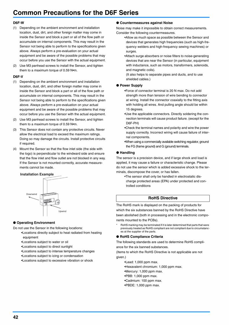
42
Common Precautions for the D6F SeriesD6F-W(1) Depending on the ambient environment and installation
location, dust, dirt, and other foreign matter may come in inside the Sensor and block a part or all of the flow path or accumulate on internal components. This may result in the Sensor not being able to perform to the specifications given above. Always perform a pre-evaluation on your actual equipment and be aware of the possible problems that may occur before you use the Sensor with the actual equipment.
(2) Use M3 panhead screws to install the Sensor, and tighten them to a maximum torque of 0.59 N•m.
D6F-V(1) Depending on the ambient environment and installation
location, dust, dirt, and other foreign matter may come in inside the Sensor and block a part or all of the flow path or accumulate on internal components. This may result in the Sensor not being able to perform to the specifications given above. Always perform a pre-evaluation on your actual equipment and be aware of the possible problems that may occur before you use the Sensor with the actual equipment.
(2) Use M3 panhead screws to install the Sensor, and tighten them to a maximum torque of 0.59 N•m.
(3) This Sensor does not contain any protective circuits. Never allow the electrical load to exceed the maximum ratings. Doing so may damage the circuits. Install protective circuits if required.
(4) Mount the Sensor so that the flow inlet side (the side with the logo) is perpendicular to the windward side and ensure that the flow inlet and flow outlet are not blocked in any way. If the Sensor is not mounted correctly, accurate measure-ments cannot be made.
● Operating Environment
Do not use the Sensor in the following locations:•Locations directly subject to heat radiated from heating equipment
•Locations subject to water or oil•Locations subject to direct sunlight•Locations subject to intense temperature changes•Locations subject to icing or condensation•Locations subject to excessive vibration or shock
● Countermeasures against Noise
Noise may make it impossible to obtain correct measurements.Consider the following countermeasures.
•Allow as much space as possible between the Sensor and devices that generates high frequencies (such as high-fre-quency welders and high-frequency sewing machines) or surges.
•Attach surge absorbers or noise filters to noise-generating devices that are near the Sensor (in particular, equipment with inductance, such as motors, transformers, solenoids, and magnetic coils).(It also helps to separate pipes and ducts, and to use shielded cables.)
● Power Supply
•Force of connector terminal is 20 N max. Do not add strength more than tension of wire bending to connector at wiring. Install the connector coaxially to the fitting axis with holding all wires. And pulling angle should be within 15 degrees.
•Use the applicable connectors. Directly soldering the con-nection terminals will cause product failure. (except for the D6F-PH)
•Check the terminal names and polarity and wire the power supply correctly. Incorrect wiring will cause failure of inter-nal components.
•When using a commercially available switching regulator, ground the FG (frame ground) and G (ground) terminals.
● Handling
The sensor is a precision device, and if large shock and load is applied, it may cause a failure or characteristic change. Please do not use the sensor which is added excessive shock to the ter-minals, discompose the cover, or has fallen.
•The sensor shall only be handled in electrostatic dis-charge protected areas (EPA) under protected and con-trolled conditions
The RoHS mark is displayed on the packing of products for
which the six substances banned by the RoHS Directive have
been abolished (both in processing and in the electronic compo-
nents mounted to the PCBs).* RoHS marking may be terminated if it is later determined that parts that were
previously treated as RoHS compliant are not compliant due to circumstanc-es at the supplier of the parts.
● RoHS Compliance Criteria
The following standards are used to determine RoHS compli-
ance for the six banned substances.
(Items to which the RoHS Directive is not applicable are not
given.)
•Lead: 1,000 ppm max.•Hexavalent chromium: 1,000 ppm max.•Mercury: 1,000 ppm max.•PBB: 1,000 ppm max.•Cadmium: 100 ppm max.•PBDE: 1,000 ppm max.
Downwind
Upwind
Installation Example
RoHS Directive

Terms and Conditions AgreementRead and understand this catalog.
Please read and understand this catalog before purchasing the products. Please consult your OMRON representative if you have any questions or comments.
Warranties.(a) Exclusive Warranty. Omron’s exclusive warranty is that the Products will be free from defects in materials and workmanship
for a period of twelve months from the date of sale by Omron (or such other period expressed in writing by Omron). Omron disclaims all other warranties, express or implied.
(b) Limitations. OMRON MAKES NO WARRANTY OR REPRESENTATION, EXPRESS OR IMPLIED, ABOUT NON-INFRINGEMENT, MERCHANTABILITY OR FITNESS FOR A PARTICULAR PURPOSE OF THE PRODUCTS. BUYER ACKNOWLEDGES THAT IT ALONE HAS DETERMINED THAT THE PRODUCTS WILL SUITABLY MEET THE REQUIREMENTS OF THEIR INTENDED USE.
Omron further disclaims all warranties and responsibility of any type for claims or expenses based on infringement by the Products or otherwise of any intellectual property right. (c) Buyer Remedy. Omron’s sole obligation hereunder shall be, at Omron’s election, to (i) replace (in the form originally shipped with Buyer responsible for labor charges for removal or replacement thereof) the non-complying Product, (ii) repair the non-complying Product, or (iii) repay or credit Buyer an amount equal to the purchase price of the non-complying Product; provided that in no event shall Omron be responsible for warranty, repair, indemnity or any other claims or expenses regarding the Products unless Omron’s analysis confirms that the Products were properly handled, stored, installed and maintained and not subject to contamination, abuse, misuse or inappropriate modification. Return of any Products by Buyer must be approved in writing by Omron before shipment. Omron Companies shall not be liable for the suitability or unsuitability or the results from the use of Products in combination with any electrical or electronic components, circuits, system assemblies or any other materials or substances or environments. Any advice, recommendations or information given orally or in writing, are not to be construed as an amendment or addition to the above warranty.
See http://www.omron.com/global/ or contact your Omron representative for published information.
Limitation on Liability; Etc.OMRON COMPANIES SHALL NOT BE LIABLE FOR SPECIAL, INDIRECT, INCIDENTAL, OR CONSEQUENTIAL DAMAGES, LOSS OF PROFITS OR PRODUCTION OR COMMERCIAL LOSS IN ANY WAY CONNECTED WITH THE PRODUCTS, WHETHER SUCH CLAIM IS BASED IN CONTRACT, WARRANTY, NEGLIGENCE OR STRICT LIABILITY.
Further, in no event shall liability of Omron Companies exceed the individual price of the Product on which liability is asserted.
Suitability of Use.Omron Companies shall not be responsible for conformity with any standards, codes or regulations which apply to the combination of the Product in the Buyer’s application or use of the Product. At Buyer’s request, Omron will provide applicable third party certification documents identifying ratings and limitations of use which apply to the Product. This information by itself is not sufficient for a complete determination of the suitability of the Product in combination with the end product, machine, system, or other application or use. Buyer shall be solely responsible for determining appropriateness of the particular Product with respect to Buyer’s application, product or system. Buyer shall take application responsibility in all cases.
NEVER USE THE PRODUCT FOR AN APPLICATION INVOLVING SERIOUS RISK TO LIFE OR PROPERTY OR IN LARGE QUANTITIES WITHOUT ENSURING THAT THE SYSTEM AS A WHOLE HAS BEEN DESIGNED TO ADDRESS THE RISKS, AND THAT THE OMRON PRODUCT(S) IS PROPERLY RATED AND INSTALLED FOR THE INTENDED USE WITHIN THE OVERALL EQUIPMENT OR SYSTEM.
Programmable Products.Omron Companies shall not be responsible for the user’s programming of a programmable Product, or any consequence thereof.
Performance Data.Data presented in Omron Company websites, catalogs and other materials is provided as a guide for the user in determining suitability and does not constitute a warranty. It may represent the result of Omron’s test conditions, and the user must correlate it to actual application requirements. Actual performance is subject to the Omron’s Warranty and Limitations of Liability.
Change in Specifications.Product specifications and accessories may be changed at any time based on improvements and other reasons. It is our practice to change part numbers when published ratings or features are changed, or when significant construction changes are made. However, some specifications of the Product may be changed without any notice. When in doubt, special part numbers may be assigned to fix or establish key specifications for your application. Please consult with your Omron’s representative at any time to confirm actual specifications of purchased Product.
Errors and Omissions.Information presented by Omron Companies has been checked and is believed to be accurate; however, no responsibility is assumed for clerical, typographical or proofreading errors or omissions.

OMRON CorporationElectronic and Mechanical Components Company
Regional Contact
Cat. No. X211-E1-060318-0.1M(0316)(O)
Americas Europehttps://www.components.omron.com/ http://components.omron.eu/
Asia-Pacific China https://ecb.omron.com.sg/ https://www.ecb.omron.com.cn/
Korea Japanhttps://www.omron-ecb.co.kr/ https://www.omron.co.jp/ecb/
In the interest of product improvement, specifications are subject to change without notice. © OMRON Corporation 2018 All Rights Reserved.
Please check each region's Terms & Conditions by region website.